EP1628005B1 - Carburetor electronic control system - Google Patents
Carburetor electronic control system Download PDFInfo
- Publication number
- EP1628005B1 EP1628005B1 EP05017129A EP05017129A EP1628005B1 EP 1628005 B1 EP1628005 B1 EP 1628005B1 EP 05017129 A EP05017129 A EP 05017129A EP 05017129 A EP05017129 A EP 05017129A EP 1628005 B1 EP1628005 B1 EP 1628005B1
- Authority
- EP
- European Patent Office
- Prior art keywords
- electronic control
- carburetor
- lever
- choke valve
- transmission device
- Prior art date
- Legal status (The legal status is an assumption and is not a legal conclusion. Google has not performed a legal analysis and makes no representation as to the accuracy of the status listed.)
- Expired - Fee Related
Links
Images


Classifications
-
- F—MECHANICAL ENGINEERING; LIGHTING; HEATING; WEAPONS; BLASTING
- F02—COMBUSTION ENGINES; HOT-GAS OR COMBUSTION-PRODUCT ENGINE PLANTS
- F02M—SUPPLYING COMBUSTION ENGINES IN GENERAL WITH COMBUSTIBLE MIXTURES OR CONSTITUENTS THEREOF
- F02M19/00—Details, component parts, or accessories of carburettors, not provided for in, or of interest apart from, the apparatus of groups F02M1/00 - F02M17/00
- F02M19/12—External control gear, e.g. having dash-pots
-
- F—MECHANICAL ENGINEERING; LIGHTING; HEATING; WEAPONS; BLASTING
- F02—COMBUSTION ENGINES; HOT-GAS OR COMBUSTION-PRODUCT ENGINE PLANTS
- F02D—CONTROLLING COMBUSTION ENGINES
- F02D9/00—Controlling engines by throttling air or fuel-and-air induction conduits or exhaust conduits
- F02D9/02—Controlling engines by throttling air or fuel-and-air induction conduits or exhaust conduits concerning induction conduits
-
- F—MECHANICAL ENGINEERING; LIGHTING; HEATING; WEAPONS; BLASTING
- F02—COMBUSTION ENGINES; HOT-GAS OR COMBUSTION-PRODUCT ENGINE PLANTS
- F02D—CONTROLLING COMBUSTION ENGINES
- F02D9/00—Controlling engines by throttling air or fuel-and-air induction conduits or exhaust conduits
- F02D9/08—Throttle valves specially adapted therefor; Arrangements of such valves in conduits
- F02D9/10—Throttle valves specially adapted therefor; Arrangements of such valves in conduits having pivotally-mounted flaps
- F02D9/1065—Mechanical control linkage between an actuator and the flap, e.g. including levers, gears, springs, clutches, limit stops of the like
-
- F—MECHANICAL ENGINEERING; LIGHTING; HEATING; WEAPONS; BLASTING
- F02—COMBUSTION ENGINES; HOT-GAS OR COMBUSTION-PRODUCT ENGINE PLANTS
- F02M—SUPPLYING COMBUSTION ENGINES IN GENERAL WITH COMBUSTIBLE MIXTURES OR CONSTITUENTS THEREOF
- F02M9/00—Carburettors having air or fuel-air mixture passage throttling valves other than of butterfly type; Carburettors having fuel-air mixing chambers of variable shape or position
-
- F—MECHANICAL ENGINEERING; LIGHTING; HEATING; WEAPONS; BLASTING
- F02—COMBUSTION ENGINES; HOT-GAS OR COMBUSTION-PRODUCT ENGINE PLANTS
- F02D—CONTROLLING COMBUSTION ENGINES
- F02D9/00—Controlling engines by throttling air or fuel-and-air induction conduits or exhaust conduits
- F02D9/02—Controlling engines by throttling air or fuel-and-air induction conduits or exhaust conduits concerning induction conduits
- F02D2009/0201—Arrangements; Control features; Details thereof
- F02D2009/0262—Arrangements; Control features; Details thereof having two or more levers on the throttle shaft
-
- Y—GENERAL TAGGING OF NEW TECHNOLOGICAL DEVELOPMENTS; GENERAL TAGGING OF CROSS-SECTIONAL TECHNOLOGIES SPANNING OVER SEVERAL SECTIONS OF THE IPC; TECHNICAL SUBJECTS COVERED BY FORMER USPC CROSS-REFERENCE ART COLLECTIONS [XRACs] AND DIGESTS
- Y10—TECHNICAL SUBJECTS COVERED BY FORMER USPC
- Y10S—TECHNICAL SUBJECTS COVERED BY FORMER USPC CROSS-REFERENCE ART COLLECTIONS [XRACs] AND DIGESTS
- Y10S261/00—Gas and liquid contact apparatus
- Y10S261/74—Valve actuation; electrical
Definitions
- the present invention relates to a carburetor electronic control system that is mainly applied to a general purpose engine, and particularly to an improvement in a carburetor electronic control system that includes a transmission device coupled to a valve such as a choke valve or a throttle valve for opening and closing an intake path of a carburetor, an electric actuator for making the valve open and close via the transmission device, and an electronic control unit for controlling the operation of the electric actuator.
- a transmission device coupled to a valve such as a choke valve or a throttle valve for opening and closing an intake path of a carburetor
- an electric actuator for making the valve open and close via the transmission device
- an electronic control unit for controlling the operation of the electric actuator.
- Such a carburetor electronic control system is known from Japanese Utility Model Registration Application Laid-open No. 56-150834 .
- US 2002/0029760 A1 discloses a throttle device that comprises a transmission chamber that houses and holds the transmission device and a drive chamber that houses and holds an electric actuator, where the transmission chamber is, not on the carburetor side but opposite thereto according to the preamble part of claim 1.
- a general throttle device is also disclosed in US 2003/0196638 A1 . It describes a throttle system for a general-purpose engine.
- the throttle system comprises a link or gear mechanism, which transmits the output of an actuator to the throttle valve.
- the present invention has been accomplished under the above-mentioned circumstances, and it is an object thereof to provide a carburetor electronic control system that enables a transmission device, an electric actuator, and an electronic control unit to be housed in a common casing, thereby contributing to a reduction in the dimensions of the casing and consequently making compact the entire engine including a carburetor.
- valve corresponds to a choke valve 7 and a throttle valve 8 of an embodiment of the present invention, which will be described later
- the electric actuator corresponds to first and second electric actuators 20 and 21 of the embodiment
- the transmission device corresponds to first and second transmission devices 24 and 25 of the embodiment.
- the transmission device, the electric actuator, and the electronic control unit can be housed in the common casing, thereby reducing the dimensions of the casing which is mounted on one side of the carburetor, and consequently making compact the entire engine including the carburetor.
- the transmission device and the electric actuator are housed and held in the transmission chamber and the drive chamber, respectively, which are defined within the casing by the partition plate, it is possible to avoid interference between the transmission device and a wire harness extending from the electric actuator, thereby preventing any damage to the wire harness.
- the transmission device and the electric actuator are held within the casing main body, and at least part of the lid is formed from the electronic control unit. Therefore, it is possible to house the transmission device, the electric actuator, and the electronic control unit in the common casing, thereby reducing the dimensions of the casing which is mounted on one side of the carburetor, and consequently enabling the entire engine including the carburetor to be made compact.
- the valve is a choke valve
- the transmission device coupled thereto comprises a pinion fixedly provided on an output shaft of the electric actuator, a large diameter gear meshing with the pinion, a first lever that pivots together with the large diameter gear, and a second lever that is fixedly provided on a valve shaft of the choke valve and is pivoted by the first lever; and a structure with which the first and second levers are coupled is arranged so that a lever ratio between the first lever and the second lever increases in shifting from a medium-opening degree position of the choke valve to a fully opened position.
- the lever ratio between the first lever and the second lever in the transmission device increases in shifting from the medium-opening degree position of the choke valve to the fully opened position, when the electric actuator makes the choke valve close from the fully opened position, a sufficiently large torque can be applied to the choke valve. Therefore, even if the choke valve is in an iced state, the icing can be crushed when starting the engine, thus reliably closing the choke valve.
- it is unnecessary in the transmission device to employ a reduction gear apart from the pinion and the large diameter gear it is possible to make the transmission device compact, consequently reduce the capacity of the transmission chamber, and contribute to making the casing compact. Furthermore, there is no need to give the pinion and the large diameter gear an excessive gear ratio, or concerns about degradation in the tooth base strength of the gears due to an excessive reduction in the module thereof.
- the structure with which the first and second levers are coupled comprises a connecting pin that is projectingly provided on a side face at an extremity of one of the first and second levers, and an oblong hole that is provided in the other one of the first and second levers and extends in the longitudinal direction thereof, the connecting pin slidably engaging with the oblong hole; and the lever ratio between the first lever and the second lever increases in shifting from the medium-opening degree position of the choke valve to the fully opened position by changing an effective arm length of the first lever or the second lever according to a change in the opening degree of the choke valve.
- the valve is a choke valve; the transmission device coupled thereto and the electric actuator are housed within the casing mounted on one side face of the carburetor; and the transmission device is provided with a relief mechanism which allows the choke valve to be opened by intake negative pressure that is equal to or higher than a predetermined value and that is generated in the intake path, the relief mechanism being disposed between and offset from the top of an output shaft of the electric actuator and the top of a valve shaft of the choke valve.
- the relief mechanism is positioned so as to be offset from the top of the output shaft of the electric actuator and the top of the valve shaft of the choke valve, the relief mechanism is not superimposed on the output shaft of the electric actuator or the valve shaft of the choke valve. Therefore, it is possible to make flat the casing for housing the transmission device and the electric actuator, so that the entire engine including the carburetor can be made compact.
- the electronic control unit comprises a board that has wiring of an electronic control circuit printed thereon and is disposed so as to close the open face of the casing main body, and various types of electronic components that are mounted on a side of the board that faces the interior of the casing main body; and among the various types of electronic components, tall large electronic components and the electric actuator are disposed on one side and the other side respectively within the casing main body.
- the electric actuator and the large electronic components are arranged in a staggered manner, they can be housed efficiently within the casing. Therefore, it is possible to greatly reduce dead space within the casing, thus contributing to making the casing compact.
- the lid comprises the electronic control unit and a cover that is fixed to the casing main body so as to hold the electronic control unit between the cover and the casing main body.
- the open face of the casing main body is blocked by the electronic control unit, and the electric control unit can be fixed reliably to the casing main body while protecting the electronic control unit with the cover.
- a soft synthetic resin coating is formed on surfaces of the board and the various types of electronic components so as to cover the surfaces, the coating being in intimate contact with the open end face of the casing main body.
- the seventh feature of the present invention not only can the coating of the soft synthetic resin formed on the surfaces of the board and the various types of electronic components seal the board and the various types of electronic components, but also the lid and the casing main body can be sealed together. Therefore, it is unnecessary to employ a seal used exclusively for this purpose, thereby contributing to a reduction in the number of components. Furthermore, since the above-mentioned coating is formed with a uniform thickness along the surfaces of the board and the various types of electronic components, there are no wastefully thick parts which would otherwise interfere with the staggered arrangement of the electric actuator and the large electronic components, thus contributing to making the casing compact.
- a soft synthetic resin coating is formed on a surface of the electronic control unit so as to cover the surface, the coating being in intimate contact with the open end face of the casing main body.
- the coating of the soft synthetic resin formed on the surface of the electronic control unit seal the electronic control unit, but also the lid and the casing main body can be sealed together.
- the above-mentioned coating is formed with a uniform thickness along the surface of the electronic control unit. Therefore, there are no wastefully thick parts which would otherwise interfere with the staggered arrangement of the electric actuator and the large electronic components, thus contributing to making the casing compact.
- an engine main body 1 of a general purpose engine E includes: a crank case 2 having a mounting flange 2a on a lower face thereof and horizontally supporting a crank shaft 4; and a cylinder 3 projecting obliquely upward on one side from the crank case 2.
- a recoil type engine starter 5 for cranking the crank shaft 4 is mounted on a front side of the crank case 2.
- Mounted on the engine main body 1 are a fuel tank T disposed above the crank case 2, and an air cleaner A and an exhaust muffler M adjoining the fuel tank T above the cylinder 3.
- Attached to one side of a head part of the cylinder 3 is a carburetor C for supplying into the cylinder 3 an air-fuel mixture formed by taking in air through the air cleaner A.
- the carburetor C has an intake path 6 communicating with an intake port of the head part of the cylinder 3.
- a choke valve 7 and a throttle valve 8 are disposed in the intake path 6, sequentially from the upstream side, that is, from the air cleaner A side.
- a fuel nozzle (not illustrated) opens in a venturi part of the intake path 6 in a middle section between the two valves 7 and 8.
- Both the choke valve 7 and the throttle valve 8 are of a butterfly type, in which they are opened and closed by pivoting of valve shafts 7a and 8a.
- An electronic control system D for automatically controlling the degree of opening of the choke valve 7 and the throttle valve 8 is mounted above the carburetor C.
- the valve shaft 7a of the choke valve 7 is called a choke valve shaft 7a
- the valve shaft 8a of the throttle valve 8 is called a throttle valve shaft 8a.
- the electronic control system D is explained by reference to FIG. 4 to FIG. 14 .
- a casing 10 of the electronic control system D for the valves includes: a casing main body 11 having a base wall 11 a joined to an upper end face of the carburetor C; and a lid 12 joined to the casing main body 11 so as to close an open face thereof.
- the lid 12 includes an electronic control unit 12a and a cover 12b.
- the electronic control unit 12a is disposed so as to be superimposed on the open end face of the casing main body 11.
- the cover 12b is made of sheet steel covering the electronic control unit 12a and joined to the casing main body 11 by bolts 13 so as to hold the electronic control unit 12a between the steel sheet cover 12b and the casing main body 11.
- the electronic control unit 12a which closes the open face of the casing main body 11, is therefore fixed to the casing main body 11 while being protected by the cover 12b.
- a partition plate 16 is provided within the casing main body 11 to divide the interior of the casing 10 into a transmission chamber 14 on the base wall 11 a side and a drive chamber 15 on the lid 12 side, the partition 16 being a separate body from the casing main body 11.
- the partition plate 16 is secured to the carburetor C together with the base wall 11 a by a plurality of bolts 17.
- An opening 18 is provided in the base wall 11 a of the casing main body 11.
- a depression 14a corresponding to the opening 18 is provided on the upper end face of the carburetor C.
- the depression 14a acts as part of the transmission chamber 14.
- Outer end parts of the choke valve shaft 7a and the throttle valve shaft 8a are arranged so as to face the depression 14a.
- a first electric motor 20 and a second electric motor 21 are mounted on the partition plate 16 by screws 22 and 23 respectively in the drive chamber 15. Disposed in the transmission chamber 14 are a first transmission device 24 for transmitting an output torque of the first electric motor 20 to the choke valve shaft 7a, and a second transmission device 25 for transmitting a driving force of the second electric motor 21 to the throttle valve shaft 8a. In this way, the first and second electric motors 20 and 21 and the first and second transmission devices 24 and 25 are housed in the casing 10 and protected.
- the first transmission device 24 includes: a first pinion 27 secured to an output shaft 20a of the first electric motor 20; a first sector gear 29 that is rotatably supported on a first support shaft 28 having opposite end parts thereof supported on the partition plate 16 and the carburetor C and that meshes with the first pinion 27; a relief lever 30 supported on the first support shaft 28 while being relatively rotatably superimposed on the first sector gear 29; and a choke lever 32 formed integrally with the outer end part of the choke valve shaft 7a and joined to the relief lever 30.
- a relief spring 31 which is a torsional coil spring, is mounted around the first support shaft 28. With a fixed set load, the relief spring 31 urges the first sector gear 29 and the relief lever 30 in a direction that makes the abutment pieces 29a and 30a abut against each other.
- the structure linking the relief lever 30 and the choke lever 32 to each other is established by slidably engaging a connecting pin 34 projectingly provided on a side face at an extremity of the relief lever 30 with an oblong hole 35 that is provided in the choke lever 32 and that extends in the longitudinal direction of the lever 32.
- the output torque of the first electric motor 20 is thus reduced and transmitted from the first pinion 27 to the first sector gear 29. Since the first sector gear 29 and the relief lever 30 are usually coupled via the abutment pieces 29a, 30a and the relief spring 31 to integrally pivot, the output torque of the first electric motor 20 transmitted to the first sector gear 29 can be transmitted from the relief lever 30 to the choke lever 32 and the choke valve shaft 7a, thus enabling the choke valve 7 to be opened and closed.
- the choke valve shaft 7a is positioned offset to one side from the center of the intake path 6, and the choke valve 7 is inclined relative to the central axis of the intake path 6 so that, in a fully closed state, a side of the choke valve 7 that has a larger rotational radius is on the downstream side of the intake path 6 relative to a side thereof that has a smaller rotational radius.
- the choke valve 7 can be opened regardless of the operation of the first electric motor 20, to a point at which the difference between the rotational moment due to the intake negative pressure imposed on the side of the choke valve 7 that has the larger rotational radius and the rotational moment due to the intake negative pressure imposed on the side of the choke valve 7 that has the smaller rotational radius, balances the rotational moment due to the relief spring 31 (see FIG. 11 ).
- the relief lever 30 and the relief spring 31 thus form a relief mechanism 33.
- the relief lever 30 and relief spring 31 are supported on the first support shaft 28, and are therefore positioned so as to be offset from the top of the output shaft 20a of the first electric motor 20 and the top of the choke valve shaft 7a.
- the relief lever 30 and the choke lever 32 are arranged at an exactly or approximately right angle when the choke valve 7 is in a fully opened position and in a fully closed position, and the connecting pin 34 is positioned at the end of the oblong hole 35 that is farther from the choke valve shaft 7a.
- the relief lever 30 and the choke lever 32 are arranged in a straight line, and the connecting pin 34 is positioned at the other end of the long hole 35 that is closer to the choke valve shaft 7a. Therefore, the effective arm length of the choke lever 32 becomes a maximum when the choke valve 7 is in fully opened and fully closed positions, and becomes a minimum when the choke valve 7 is at the predetermined medium opening-degree.
- the lever ratio between the relief lever 30 and the choke lever 32 changes, as shown in FIG. 14 , such that it becomes a maximum when the choke valve 7 is in fully opened and fully closed positions and becomes a minimum when the choke valve 7 is at the predetermined medium opening-degree.
- the engine E can be started because a choke valve forced closure mechanism 37 that forcibly closes the choke valve 7 is provided to adjoin one side of the relief lever 30.
- the choke valve forced closure mechanism 37 includes: a lever shaft 38 having opposite end parts rotatably supported on the base wall 11 a of the casing main body 11 and the carburetor C; an operating lever 39 coupled to the lever shaft 38 and disposed beneath the casing main body 11; an actuating arm 40 formed integrally with the lever shaft 38 and facing one side of the abutment piece 30a of the relief lever 30; and a return spring 41 which is a torsional coil spring and is connected to the actuating arm 40 so as to urge the actuating arm 40 in a direction that detaches it from the abutment piece 30a, that is, in a retraction direction.
- the actuating arm 40 pushes the abutment piece 30a of the relief lever 30 in a direction that closes the choke valve 7.
- the operating lever 39 is usually positioned so that it is not accidentally hit by any other objects, for example, in such a manner that the extremity of the operating lever 39 faces the engine E side. With this arrangement, erroneous operation of the operating lever 39 can be avoided.
- the second transmission device 25 is now explained by reference to FIG. 4 , FIG. 6 , and FIG. 7 .
- the second transmission device 25 includes: a second pinion 44 secured to the output shaft 21 a of the second electric motor 21; a second sector gear 46 that is rotatably supported on a second support shaft 45 having opposite end parts supported on the partition plate 16 and the carburetor C and that meshes with the second pinion 44; a non-constant speed drive gear 47 integrally molded with one side of the second sector gear 46 in the axial direction; and a non-constant speed driven gear 48 secured to an outer end part of the throttle valve shaft 8a and meshing with the non-constant speed drive gear 47.
- a throttle valve closing spring 49 Connected to the non-constant speed driven gear 48 is a throttle valve closing spring 49 that urges the non-constant speed driven gear 48 in a direction that closes the throttle valve 8.
- both the non-constant-speed drive and driven gears 47 and 48 are designed so that the gear ratio, that is, the reduction ratio between them decreases in response to an increase in the degree of opening of the throttle valve 8. Therefore, the reduction ratio is a maximum when the throttle valve 8 is in a fully closed state. With this arrangement, it becomes possible to minutely control the degree of opening in a low opening-degree region, which includes an idle opening-degree of the throttle valve 8, by operation of the second electric motor 21.
- the first and second support shafts 28 and 45 which are components of the first and second transmission devices 24 and 25, are supported by opposite end parts thereof being fitted into the carburetor C and the partition plate 16, and serves as positioning pins for positioning the partition plate 16 at a fixed position relative to the carburetor C. Therefore, it is unnecessary to employ a positioning pin used exclusively for this purpose, thereby contributing to a reduction in the number of components.
- the first and second electric motors 20 and 21 are mounted on the partition plate 16, it is possible to appropriately couple the first electric motor 20 to the first transmission device 24, and couple the second electric motor 21 to the second transmission device 25.
- the electronic control unit 12a is now explained by reference to FIG. 4 , FIG. 5 , and FIG. 13 .
- the electronic control unit 12a is formed by mounting various types of electronic components 51 to 54 on an electric circuit of a substantially rectangular printed wiring board 50, and connecting an input connector 55 and an output connector 56 to longitudinally opposite ends of the board 50.
- the board 50 is positioned parallel to the base wall 11 a of the casing main body 11.
- Mounted on an inside face of the board 50 facing the drive chamber 15 are, for example, tall large electronic components such as a transformer 51, capacitors 52a to 52c and a heatsink 53, as well as thin low-profile electronic components such as a CPU 54.
- a pilot lamp 68 is mounted on an outside face of the board 50.
- the large electronic components 51 to 53 and the low-profile electronic component 54 are thus contained within the drive chamber 15, the large electronic components 51 to 53 being positioned in the vicinity of the partition plate 16 on one side of the drive chamber 15, and the low-profile electronic component 54 being positioned on the other side of the drive chamber 15.
- the first and second electric motors 20 and 21 are positioned in the vicinity of the board 50 and the low-profile electronic component 54 on said other side of the drive chamber 15. In this way, the first and second electric motors 20, 21 and the large electronic components 51 to 53 are arranged in a staggered manner.
- the first and second electric motors 20, 21 and the large electronic components 51 to 53 can be efficiently housed in the drive chamber 15. Therefore, the dead space in the drive chamber 15 can be greatly reduced and the volume of the drive chamber 15 can be made smaller, thereby reducing the size of the casing 10 and consequently making compact the entire engine E including the carburetor C equipped with the electronic control system D.
- a flexible synthetic resin coating 57 for covering these components is formed by a hot-melt molding method or an injection molding method. Since this coating 57 is formed with a substantially uniform thickness along the shapes of the board 50 and the various types of electronic components 51 to 54, there are no unnecessary thick parts, and it does not interfere with the staggered arrangement of the first and second electric motors 20, 21 and the large electronic components 51 to 53, thus contributing to a reduction in the size of the casing 10.
- this coating 57 exhibits the function of tightly sealing opposing faces of the casing main body 11 and the cover 12b, it is unnecessary to employ a seal member used exclusively for this purpose, thereby contributing to a reduction in the number of components and an improvement of the ease of assembly.
- a light-emitting part of the pilot lamp 68 ( FIG. 5 ) is positioned so as to run through the coating 57 and the cover 12b, and its lit and unlit states accompanying a main switch 64 being turned on or off can be visually identified from outside the lid 12.
- electric power of the battery 60, an output signal of a rotational speed setting device 61 that sets a desired rotational speed for the engine E, an output signal of a rotational speed sensor 62 for detecting the rotational speed of the engine E, an output signal of a temperature sensor 63 for detecting a temperature of the engine E, etc., are input via the input connector 55 into the electronic control unit 12a.
- the main switch 64 is provided on an energizing circuit between the battery 60 and the input connector 55.
- an internal connector 67 Connected to the output connector 56 is an internal connector 67 (see FIG. 6 ), which is connected to wire harnesses 65 and 66 for energization of the first and second electric motors 20 and 21.
- the first electric motor 20 is operated by the power of the battery 60 based on the output signal of the temperature sensor 63, and the choke valve 7 is operated via the first transmission device 24 to a start opening-degree according to the engine temperature at that time.
- the choke valve 7 is driven to a fully closed position as shown in FIG. 9 ; and when the engine E is hot, the choke valve 7 is maintained at a fully opened position as shown in FIG. 10 .
- an excessive intake negative pressure of the engine E acts on the choke valve 7 which is in a fully closed state.
- the choke valve 7 is automatically opened (see FIG. 11 ), regardless of operation of the first electric motor 20, until the difference between the rotational moment due to the intake negative pressure acting on the side of the choke valve 7 having a large rotational radius and the rotational moment due to the intake negative pressure acting on the side of the choke valve 7 having a small rotational radius balances the rotational moment due to the relief spring 31, the excessive intake negative pressure can be eliminated, thus preventing the air-fuel mixture from becoming too rich to ensure good warming-up conditions for the engine E.
- the relief mechanism 33 which includes the relief lever 30 and the relief spring 31, is positioned so as to be offset from the top of the output shaft 20a of the first electric motor 20 and the top of the choke valve shaft 7a, the relief mechanism 33 is not superimposed on the output shaft 20a of the first electric motor 20 or the choke valve shaft 7a, and the transmission chamber 14 housing the first transmission device 24 can be made flat while providing the relief mechanism 33 in the first transmission device 24, thereby contributing to a reduction in the size of the casing 10.
- the first electric motor 20 is operated based on the output signal of the temperature sensor 63 which changes according to the engine temperature, so that the choke valve 7 is gradually opened via the first transmission device 24.
- the choke valve 7 is put in a fully opened state (see FIG. 10 ), and this state is maintained during subsequent running.
- the second electric motor 21 operates based on the output signals of the rotational speed setting device 61 and the rotational speed sensor 62, and controls opening and closing of the throttle valve 8 via the second transmission device 25 so that the engine rotational speed coincides with a desired rotational speed set by the rotational speed setting device 61, thus regulating the amount of air-fuel mixture supplied from the carburetor C to the engine E.
- Running of the engine E can be stopped by switching the main switch 64 off and operating a kill switch (not illustrated) of the engine E.
- the engine E After completing a given operation, the engine E is usually in a hot state, and thus the choke valve 7 is maintained in a fully opened state by the first electric motor 20. Therefore, after running of the engine E is stopped, the fully opened state of the choke valve 7 is maintained.
- an icing phenomenon often occurs, that is, water droplets condensed around the choke valve shaft 7a are frozen and the choke valve 7 becomes stuck. Such a phenomenon generally makes it difficult for the choke valve 7 to move to the fully closed state when the engine is started anew.
- the structure coupling the relief lever 30 and the choke lever 32 to each other is arranged so that the lever ratio of the two levers 30 and 32 is a maximum when the choke valve 7 is in fully opened and fully closed positions, and a minimum when the choke valve 7 is at the predetermined medium opening-degree. Therefore, when the engine E is cold-started and the first electric motor 20 operates in a direction that closes the choke valve 7 based on the output signal of the temperature sensor 63, a maximum torque can be applied to the choke valve shaft 7a, thus crushing ice around the choke valve shaft 7a to reliably drive the choke valve 7 from the fully opened position to the fully closed position, whereby the reliability of an autochoke function is guaranteed without any problem in the cold starting.
- the torque acting on the choke valve shaft 7a from the first electric motor 20 can be made a maximum at least when the choke valve 7 is in the fully opened position. Therefore, an increase in the number of stages of reduction gears such as the first pinion 27 and the first sector gear 29 of the first transmission device 24 can be suppressed, thereby contributing to a reduction in the size of the first transmission device 24, and consequently reducing the volume of the transmission chamber 14 and the size of the casing 10. Furthermore, an unreasonable reduction ratio need not be given to the first pinion 27 and the first sector gear 29, and there are no concerns about degradation in the tooth base strength of the gears due to an excessive reduction in the module thereof.
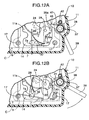
- the choke valve 7 remains open as shown in FIG. 12A , and when starting, a rich air-fuel mixture suitable for cold starting cannot be generated in the intake path 6. In such a case, as shown in FIG. 12B , the operating lever 39 of the choke valve forced closure mechanism 37 is held and pivoted against the urging force of the return spring 41.
- the actuating arm 40 which is coupled to the operating lever 39 and faces the abutment piece 30a of the relief lever 30, pushes the abutment piece 30a, and this pushing force is transmitted from the relief lever 30 to the choke lever 32 so as to close the choke valve 7 to the fully closed position; if the engine E is started in this operating state, a rich air-fuel mixture suitable for cold starting can be generated in the intake path 6, thus reliably carrying out cold starting.
- the choke valve 7 is controlled to an appropriate warm-up opening-degree, and it is therefore necessary to return the actuating arm 40 to a non-operating position retracted from the relief lever 30 so as not to interfere with the operation of the first electric motor 20.
- the actuating arm 40 can push the abutment piece 30a of the relief lever 30 only in a direction that closes the choke valve 7, and when it is held at the retracted position by a set load of the return spring 41, it merely faces the abutment piece 30a of the relief lever 30 and is put in a state in which it is detached from the first transmission device 24. Therefore, when the choke valve 7 is driven normally by the first electric motor 20, the choke valve forced closure mechanism 37 does not impose any load on the first transmission device 24, thereby preventing malfunction of or damage to the first transmission device 24.
- a carburetor electronic control system includes: transmission devices coupled to valves for opening and closing an intake path of a carburetor; electric motors that make the valves open and close via the transmission devices; and an electronic control unit for controlling the operation of the electric motors.
- the interior of a casing joined to one side face of the carburetor is divided by a partition plate into a transmission chamber on the carburetor side and a drive chamber on the opposite side.
- the transmission devices and the electric motors are housed and held in the transmission chamber and the drive chamber, respectively. Therefore, the transmission devices, the electric actuators, and the electronic control unit can be housed in a common casing, thereby reducing the dimensions of the carburetor electronic control system.
Description
- The present invention relates to a carburetor electronic control system that is mainly applied to a general purpose engine, and particularly to an improvement in a carburetor electronic control system that includes a transmission device coupled to a valve such as a choke valve or a throttle valve for opening and closing an intake path of a carburetor, an electric actuator for making the valve open and close via the transmission device, and an electronic control unit for controlling the operation of the electric actuator.
- Such a carburetor electronic control system is known from Japanese Utility Model Registration Application Laid-open
No. 56-150834 - In the conventional carburetor electronic control system, since a transmission device and an electric actuator are mounted separately from an electronic control unit on a carburetor or an engine, it is necessary to employ individual casings in order to protect them from external disturbance, resulting in that the casings become a hindrance in downsizing particularly of general purpose engines, which are used by being coupled to various types of work machines.
- Further,
US 2002/0029760 A1 discloses a throttle device that comprises a transmission chamber that houses and holds the transmission device and a drive chamber that houses and holds an electric actuator, where the transmission chamber is, not on the carburetor side but opposite thereto according to the preamble part ofclaim 1. - A general throttle device is also disclosed in
US 2003/0196638 A1 . It describes a throttle system for a general-purpose engine. The throttle system comprises a link or gear mechanism, which transmits the output of an actuator to the throttle valve. - The present invention has been accomplished under the above-mentioned circumstances, and it is an object thereof to provide a carburetor electronic control system that enables a transmission device, an electric actuator, and an electronic control unit to be housed in a common casing, thereby contributing to a reduction in the dimensions of the casing and consequently making compact the entire engine including a carburetor.
- In order to achieve the above-mentioned object, there is provided a carburetor electronic control system according to claim 1 (first feature of the invention).
- The above-mentioned valve corresponds to a
choke valve 7 and athrottle valve 8 of an embodiment of the present invention, which will be described later, the electric actuator corresponds to first and secondelectric actuators second transmission devices - With the first feature of the present invention, the transmission device, the electric actuator, and the electronic control unit can be housed in the common casing, thereby reducing the dimensions of the casing which is mounted on one side of the carburetor, and consequently making compact the entire engine including the carburetor. Moreover, since the transmission device and the electric actuator are housed and held in the transmission chamber and the drive chamber, respectively, which are defined within the casing by the partition plate, it is possible to avoid interference between the transmission device and a wire harness extending from the electric actuator, thereby preventing any damage to the wire harness.
- Furthermore, the transmission device and the electric actuator are held within the casing main body, and at least part of the lid is formed from the electronic control unit. Therefore, it is possible to house the transmission device, the electric actuator, and the electronic control unit in the common casing, thereby reducing the dimensions of the casing which is mounted on one side of the carburetor, and consequently enabling the entire engine including the carburetor to be made compact.
- According to a second feature of the present invention, in addition to the first feature, the valve is a choke valve; the transmission device coupled thereto comprises a pinion fixedly provided on an output shaft of the electric actuator, a large diameter gear meshing with the pinion, a first lever that pivots together with the large diameter gear, and a second lever that is fixedly provided on a valve shaft of the choke valve and is pivoted by the first lever; and a structure with which the first and second levers are coupled is arranged so that a lever ratio between the first lever and the second lever increases in shifting from a medium-opening degree position of the choke valve to a fully opened position.
- With the second feature of the present invention, since the lever ratio between the first lever and the second lever in the transmission device increases in shifting from the medium-opening degree position of the choke valve to the fully opened position, when the electric actuator makes the choke valve close from the fully opened position, a sufficiently large torque can be applied to the choke valve. Therefore, even if the choke valve is in an iced state, the icing can be crushed when starting the engine, thus reliably closing the choke valve. Further, since it is unnecessary in the transmission device to employ a reduction gear apart from the pinion and the large diameter gear, it is possible to make the transmission device compact, consequently reduce the capacity of the transmission chamber, and contribute to making the casing compact. Furthermore, there is no need to give the pinion and the large diameter gear an excessive gear ratio, or concerns about degradation in the tooth base strength of the gears due to an excessive reduction in the module thereof.
- According to a third feature of the present invention, in addition to the second feature, the structure with which the first and second levers are coupled comprises a connecting pin that is projectingly provided on a side face at an extremity of one of the first and second levers, and an oblong hole that is provided in the other one of the first and second levers and extends in the longitudinal direction thereof, the connecting pin slidably engaging with the oblong hole; and the lever ratio between the first lever and the second lever increases in shifting from the medium-opening degree position of the choke valve to the fully opened position by changing an effective arm length of the first lever or the second lever according to a change in the opening degree of the choke valve.
- With the third feature of the present invention, it is possible to achieve variable lever ratio characteristics between the first lever and the second lever with an extremely simple structure.
- According to a fourth feature of the present invention, in addition to the first feature, the valve is a choke valve; the transmission device coupled thereto and the electric actuator are housed within the casing mounted on one side face of the carburetor; and the transmission device is provided with a relief mechanism which allows the choke valve to be opened by intake negative pressure that is equal to or higher than a predetermined value and that is generated in the intake path, the relief mechanism being disposed between and offset from the top of an output shaft of the electric actuator and the top of a valve shaft of the choke valve.
- With the fourth feature of the present invention, since the relief mechanism is positioned so as to be offset from the top of the output shaft of the electric actuator and the top of the valve shaft of the choke valve, the relief mechanism is not superimposed on the output shaft of the electric actuator or the valve shaft of the choke valve. Therefore, it is possible to make flat the casing for housing the transmission device and the electric actuator, so that the entire engine including the carburetor can be made compact.
- According to a fifth feature of the present invention, the electronic control unit comprises a board that has wiring of an electronic control circuit printed thereon and is disposed so as to close the open face of the casing main body, and various types of electronic components that are mounted on a side of the board that faces the interior of the casing main body; and among the various types of electronic components, tall large electronic components and the electric actuator are disposed on one side and the other side respectively within the casing main body.
- With the fifth feature of the present invention, since the electric actuator and the large electronic components are arranged in a staggered manner, they can be housed efficiently within the casing. Therefore, it is possible to greatly reduce dead space within the casing, thus contributing to making the casing compact.
- According to a sixth feature of the present invention, in addition to the fifth or sixth feature, the lid comprises the electronic control unit and a cover that is fixed to the casing main body so as to hold the electronic control unit between the cover and the casing main body.
- With the sixth feature of the present invention, the open face of the casing main body is blocked by the electronic control unit, and the electric control unit can be fixed reliably to the casing main body while protecting the electronic control unit with the cover.
- According to a seventh feature of the present invention, a soft synthetic resin coating is formed on surfaces of the board and the various types of electronic components so as to cover the surfaces, the coating being in intimate contact with the open end face of the casing main body.
- With the seventh feature of the present invention, not only can the coating of the soft synthetic resin formed on the surfaces of the board and the various types of electronic components seal the board and the various types of electronic components, but also the lid and the casing main body can be sealed together. Therefore, it is unnecessary to employ a seal used exclusively for this purpose, thereby contributing to a reduction in the number of components. Furthermore, since the above-mentioned coating is formed with a uniform thickness along the surfaces of the board and the various types of electronic components, there are no wastefully thick parts which would otherwise interfere with the staggered arrangement of the electric actuator and the large electronic components, thus contributing to making the casing compact.
- According to an eighth feature of the present invention, in addition to the fifth feature, a soft synthetic resin coating is formed on a surface of the electronic control unit so as to cover the surface, the coating being in intimate contact with the open end face of the casing main body.
- With the eighth feature of the present invention, not only can the coating of the soft synthetic resin formed on the surface of the electronic control unit seal the electronic control unit, but also the lid and the casing main body can be sealed together. Moreover, the above-mentioned coating is formed with a uniform thickness along the surface of the electronic control unit. Therefore, there are no wastefully thick parts which would otherwise interfere with the staggered arrangement of the electric actuator and the large electronic components, thus contributing to making the casing compact.
- The above-mentioned object, other objects, characteristics, and advantages of the present invention will become apparent from an explanation of a preferred embodiment that will be described in detail below by reference to the attached drawings.
-
-
FIG. 1 is a front view of a general purpose engine according to an embodiment of the present invention. -
FIG. 2 is a view fromarrow 2 inFIG. 1 . -
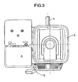
FIG. 3 is a view fromarrow 3 inFIG. 1 . -
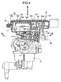
FIG. 4 is a sectional view along line 4-4 inFIG. 2 . -
FIG. 5 is a view fromarrow 5 inFIG. 4 (a plan view of an electronic control system). -
FIG. 6 is a plan view showing the electronic control system with its lid taken off. -
FIG. 7 is a plan view showing the electronic control system with its lid and partition taken off. -
FIG. 8 is a sectional view along line 8-8 inFIG. 4 . -
FIG. 9A and FIG. 9B are a plan view and a front view of a first transmission device controlling a choke valve in a fully closed state. -
FIG. 10A and FIG. 10B are a plan view and a front view of the first transmission device controlling the choke valve in a fully opened state. -
FIG. 11A and FIG. 11B are a plan view and a front view of the first transmission device showing an operating state of a relief mechanism. -
FIG. 12A and FIG. 12B are plan views showing a non-operating state and an operating state of a choke valve forced closure mechanism inFIG. 7 . -
FIG. 13 is a plan view of an electronic control unit. -
FIG. 14 is a graph showing the relationship between the degree of opening of the choke valve and the lever ratio between a relief lever and a choke lever. - Firstly, as shown in
FIG. 1 to FIG. 3 , an enginemain body 1 of a general purpose engine E includes: a crankcase 2 having a mountingflange 2a on a lower face thereof and horizontally supporting acrank shaft 4; and acylinder 3 projecting obliquely upward on one side from thecrank case 2. A recoiltype engine starter 5 for cranking thecrank shaft 4 is mounted on a front side of thecrank case 2. Mounted on the enginemain body 1 are a fuel tank T disposed above the crankcase 2, and an air cleaner A and an exhaust muffler M adjoining the fuel tank T above thecylinder 3. Attached to one side of a head part of thecylinder 3 is a carburetor C for supplying into thecylinder 3 an air-fuel mixture formed by taking in air through the air cleaner A. - As shown in
FIG. 4 andFIG. 8 , the carburetor C has anintake path 6 communicating with an intake port of the head part of thecylinder 3. In theintake path 6, sequentially from the upstream side, that is, from the air cleaner A side, achoke valve 7 and athrottle valve 8 are disposed. A fuel nozzle (not illustrated) opens in a venturi part of theintake path 6 in a middle section between the twovalves choke valve 7 and thethrottle valve 8 are of a butterfly type, in which they are opened and closed by pivoting ofvalve shafts choke valve 7 and thethrottle valve 8 is mounted above the carburetor C. Hereinafter, thevalve shaft 7a of thechoke valve 7 is called achoke valve shaft 7a, and thevalve shaft 8a of thethrottle valve 8 is called athrottle valve shaft 8a. - The electronic control system D is explained by reference to
FIG. 4 to FIG. 14 . - Firstly, in
FIG. 4 andFIG. 5 , acasing 10 of the electronic control system D for the valves includes: a casingmain body 11 having abase wall 11 a joined to an upper end face of the carburetor C; and alid 12 joined to the casingmain body 11 so as to close an open face thereof. Thelid 12 includes anelectronic control unit 12a and acover 12b. Theelectronic control unit 12a is disposed so as to be superimposed on the open end face of the casingmain body 11. Thecover 12b is made of sheet steel covering theelectronic control unit 12a and joined to the casingmain body 11 bybolts 13 so as to hold theelectronic control unit 12a between thesteel sheet cover 12b and the casingmain body 11. Theelectronic control unit 12a, which closes the open face of the casingmain body 11, is therefore fixed to the casingmain body 11 while being protected by thecover 12b. - As shown in
FIG. 4 ,FIG. 6 , andFIG. 7 , apartition plate 16 is provided within the casingmain body 11 to divide the interior of thecasing 10 into atransmission chamber 14 on thebase wall 11 a side and adrive chamber 15 on thelid 12 side, thepartition 16 being a separate body from the casingmain body 11. Thepartition plate 16 is secured to the carburetor C together with thebase wall 11 a by a plurality ofbolts 17. - An
opening 18 is provided in thebase wall 11 a of the casingmain body 11. Adepression 14a corresponding to theopening 18 is provided on the upper end face of the carburetor C. Thedepression 14a acts as part of thetransmission chamber 14. Outer end parts of thechoke valve shaft 7a and thethrottle valve shaft 8a are arranged so as to face thedepression 14a. - A first
electric motor 20 and a secondelectric motor 21 are mounted on thepartition plate 16 byscrews drive chamber 15. Disposed in thetransmission chamber 14 are afirst transmission device 24 for transmitting an output torque of the firstelectric motor 20 to thechoke valve shaft 7a, and asecond transmission device 25 for transmitting a driving force of the secondelectric motor 21 to thethrottle valve shaft 8a. In this way, the first and secondelectric motors second transmission devices casing 10 and protected. - As shown in
FIG. 7 to FIG. 9 , thefirst transmission device 24 includes: afirst pinion 27 secured to anoutput shaft 20a of the firstelectric motor 20; afirst sector gear 29 that is rotatably supported on afirst support shaft 28 having opposite end parts thereof supported on thepartition plate 16 and the carburetor C and that meshes with thefirst pinion 27; arelief lever 30 supported on thefirst support shaft 28 while being relatively rotatably superimposed on thefirst sector gear 29; and achoke lever 32 formed integrally with the outer end part of thechoke valve shaft 7a and joined to therelief lever 30. Formed on thefirst sector gear 29 and therelief lever 30 respectively areabutment pieces relief lever 30 a driving force of thefirst sector gear 29 in a direction that opens thechoke valve 7. Arelief spring 31, which is a torsional coil spring, is mounted around thefirst support shaft 28. With a fixed set load, therelief spring 31 urges thefirst sector gear 29 and therelief lever 30 in a direction that makes theabutment pieces - As clearly shown in
FIG. 9 , the structure linking therelief lever 30 and thechoke lever 32 to each other is established by slidably engaging a connectingpin 34 projectingly provided on a side face at an extremity of therelief lever 30 with anoblong hole 35 that is provided in thechoke lever 32 and that extends in the longitudinal direction of thelever 32. - The output torque of the first
electric motor 20 is thus reduced and transmitted from thefirst pinion 27 to thefirst sector gear 29. Since thefirst sector gear 29 and therelief lever 30 are usually coupled via theabutment pieces relief spring 31 to integrally pivot, the output torque of the firstelectric motor 20 transmitted to thefirst sector gear 29 can be transmitted from therelief lever 30 to thechoke lever 32 and thechoke valve shaft 7a, thus enabling thechoke valve 7 to be opened and closed. - As shown in
FIG. 8 , thechoke valve shaft 7a is positioned offset to one side from the center of theintake path 6, and thechoke valve 7 is inclined relative to the central axis of theintake path 6 so that, in a fully closed state, a side of thechoke valve 7 that has a larger rotational radius is on the downstream side of theintake path 6 relative to a side thereof that has a smaller rotational radius. Therefore, while the firstelectric motor 20 is operated so that thechoke valve 7 is fully closed or held at a very small opening-degree, if the intake negative pressure of the engine E exceeds a predetermined value, thechoke valve 7 can be opened regardless of the operation of the firstelectric motor 20, to a point at which the difference between the rotational moment due to the intake negative pressure imposed on the side of thechoke valve 7 that has the larger rotational radius and the rotational moment due to the intake negative pressure imposed on the side of thechoke valve 7 that has the smaller rotational radius, balances the rotational moment due to the relief spring 31 (seeFIG. 11 ). Therelief lever 30 and therelief spring 31 thus form arelief mechanism 33. Therelief lever 30 andrelief spring 31 are supported on thefirst support shaft 28, and are therefore positioned so as to be offset from the top of theoutput shaft 20a of the firstelectric motor 20 and the top of thechoke valve shaft 7a. - As shown in
FIG. 9 andFIG. 10 , therelief lever 30 and thechoke lever 32 are arranged at an exactly or approximately right angle when thechoke valve 7 is in a fully opened position and in a fully closed position, and the connectingpin 34 is positioned at the end of theoblong hole 35 that is farther from thechoke valve shaft 7a. When thechoke valve 7 is at a predetermined medium opening-degree, therelief lever 30 and thechoke lever 32 are arranged in a straight line, and the connectingpin 34 is positioned at the other end of thelong hole 35 that is closer to thechoke valve shaft 7a. Therefore, the effective arm length of thechoke lever 32 becomes a maximum when thechoke valve 7 is in fully opened and fully closed positions, and becomes a minimum when thechoke valve 7 is at the predetermined medium opening-degree. As a result, the lever ratio between therelief lever 30 and thechoke lever 32 changes, as shown inFIG. 14 , such that it becomes a maximum when thechoke valve 7 is in fully opened and fully closed positions and becomes a minimum when thechoke valve 7 is at the predetermined medium opening-degree. - Even if the first
electric motor 20 becomes inoperable when thechoke valve 7 is in the fully opened state due to, for example, an insufficient amount of electricity stored in a battery 60 (FIG. 13 ) which will be described later, the engine E can be started because a choke valve forcedclosure mechanism 37 that forcibly closes thechoke valve 7 is provided to adjoin one side of therelief lever 30. - As shown in
FIG. 4 ,FIG. 7 , andFIG. 12 , the choke valve forcedclosure mechanism 37 includes: alever shaft 38 having opposite end parts rotatably supported on thebase wall 11 a of the casingmain body 11 and the carburetor C; an operatinglever 39 coupled to thelever shaft 38 and disposed beneath the casingmain body 11; anactuating arm 40 formed integrally with thelever shaft 38 and facing one side of theabutment piece 30a of therelief lever 30; and areturn spring 41 which is a torsional coil spring and is connected to theactuating arm 40 so as to urge theactuating arm 40 in a direction that detaches it from theabutment piece 30a, that is, in a retraction direction. When thechoke valve 7 is fully opened, by making the operatinglever 39 pivot against the urging force of thereturn spring 41, theactuating arm 40 pushes theabutment piece 30a of therelief lever 30 in a direction that closes thechoke valve 7. - The retraction position of the operating
lever 39 and theactuating arm 40, which are connected integrally to each other, is restricted by one side of theactuating arm 40 abutting against a retainingpin 42 provided in the casingmain body 11 so as to retain the fixed end of thereturn spring 41. The operatinglever 39 is usually positioned so that it is not accidentally hit by any other objects, for example, in such a manner that the extremity of the operatinglever 39 faces the engine E side. With this arrangement, erroneous operation of the operatinglever 39 can be avoided. - The
second transmission device 25 is now explained by reference toFIG. 4 ,FIG. 6 , andFIG. 7 . - The
second transmission device 25 includes: asecond pinion 44 secured to theoutput shaft 21 a of the secondelectric motor 21; asecond sector gear 46 that is rotatably supported on asecond support shaft 45 having opposite end parts supported on thepartition plate 16 and the carburetor C and that meshes with thesecond pinion 44; a non-constantspeed drive gear 47 integrally molded with one side of thesecond sector gear 46 in the axial direction; and a non-constant speed drivengear 48 secured to an outer end part of thethrottle valve shaft 8a and meshing with the non-constantspeed drive gear 47. Connected to the non-constant speed drivengear 48 is a throttlevalve closing spring 49 that urges the non-constant speed drivengear 48 in a direction that closes thethrottle valve 8. By employing part of an elliptic gear or an eccentric gear, both the non-constant-speed drive and drivengears throttle valve 8. Therefore, the reduction ratio is a maximum when thethrottle valve 8 is in a fully closed state. With this arrangement, it becomes possible to minutely control the degree of opening in a low opening-degree region, which includes an idle opening-degree of thethrottle valve 8, by operation of the secondelectric motor 21. - The first and
second support shafts second transmission devices partition plate 16, and serves as positioning pins for positioning thepartition plate 16 at a fixed position relative to the carburetor C. Therefore, it is unnecessary to employ a positioning pin used exclusively for this purpose, thereby contributing to a reduction in the number of components. With this positioning of thepartition plate 16, it is possible to appropriately couple thefirst transmission device 24 to thechoke valve shaft 7a, and couple thesecond transmission device 25 to thethrottle valve 8. Moreover, since the first and secondelectric motors partition plate 16, it is possible to appropriately couple the firstelectric motor 20 to thefirst transmission device 24, and couple the secondelectric motor 21 to thesecond transmission device 25. - The
electronic control unit 12a is now explained by reference toFIG. 4 ,FIG. 5 , andFIG. 13 . - As shown in
FIG. 4 andFIG. 5 , theelectronic control unit 12a is formed by mounting various types of electronic components 51 to 54 on an electric circuit of a substantially rectangular printedwiring board 50, and connecting aninput connector 55 and anoutput connector 56 to longitudinally opposite ends of theboard 50. Theboard 50 is positioned parallel to thebase wall 11 a of the casingmain body 11. Mounted on an inside face of theboard 50 facing thedrive chamber 15 are, for example, tall large electronic components such as a transformer 51,capacitors 52a to 52c and aheatsink 53, as well as thin low-profile electronic components such as aCPU 54. Apilot lamp 68 is mounted on an outside face of theboard 50. The large electronic components 51 to 53 and the low-profileelectronic component 54 are thus contained within thedrive chamber 15, the large electronic components 51 to 53 being positioned in the vicinity of thepartition plate 16 on one side of thedrive chamber 15, and the low-profileelectronic component 54 being positioned on the other side of thedrive chamber 15. The first and secondelectric motors board 50 and the low-profileelectronic component 54 on said other side of thedrive chamber 15. In this way, the first and secondelectric motors - With this staggered arrangement, the first and second
electric motors drive chamber 15. Therefore, the dead space in thedrive chamber 15 can be greatly reduced and the volume of thedrive chamber 15 can be made smaller, thereby reducing the size of thecasing 10 and consequently making compact the entire engine E including the carburetor C equipped with the electronic control system D. - In order to seal the
board 50 mounting thereon the various types of electronic components 51 to 54, a flexiblesynthetic resin coating 57 for covering these components is formed by a hot-melt molding method or an injection molding method. Since thiscoating 57 is formed with a substantially uniform thickness along the shapes of theboard 50 and the various types of electronic components 51 to 54, there are no unnecessary thick parts, and it does not interfere with the staggered arrangement of the first and secondelectric motors casing 10. Furthermore, since thiscoating 57 exhibits the function of tightly sealing opposing faces of the casingmain body 11 and thecover 12b, it is unnecessary to employ a seal member used exclusively for this purpose, thereby contributing to a reduction in the number of components and an improvement of the ease of assembly. - A light-emitting part of the pilot lamp 68 (
FIG. 5 ) is positioned so as to run through thecoating 57 and thecover 12b, and its lit and unlit states accompanying amain switch 64 being turned on or off can be visually identified from outside thelid 12. - In
FIG. 13 , electric power of thebattery 60, an output signal of a rotationalspeed setting device 61 that sets a desired rotational speed for the engine E, an output signal of arotational speed sensor 62 for detecting the rotational speed of the engine E, an output signal of atemperature sensor 63 for detecting a temperature of the engine E, etc., are input via theinput connector 55 into theelectronic control unit 12a. Themain switch 64 is provided on an energizing circuit between thebattery 60 and theinput connector 55. - Connected to the
output connector 56 is an internal connector 67 (seeFIG. 6 ), which is connected to wireharnesses electric motors - The operation of this embodiment is now explained.
- In the
electronic control unit 12a, when themain switch 64 is switched on, the firstelectric motor 20 is operated by the power of thebattery 60 based on the output signal of thetemperature sensor 63, and thechoke valve 7 is operated via thefirst transmission device 24 to a start opening-degree according to the engine temperature at that time. For example, when the engine E is cold, thechoke valve 7 is driven to a fully closed position as shown inFIG. 9 ; and when the engine E is hot, thechoke valve 7 is maintained at a fully opened position as shown inFIG. 10 . Since the start opening-degree of thechoke valve 7 is controlled in this way, by subsequently operating therecoil starter 5 for cranking in order to start the engine E, an air-fuel mixture having a concentration suitable for starting the engine at that time is formed in theintake path 6 of the carburetor C, thus always starting the engine E easily. - Immediately after starting the engine in a cold state, an excessive intake negative pressure of the engine E acts on the
choke valve 7 which is in a fully closed state. As a result, as described above, since thechoke valve 7 is automatically opened (seeFIG. 11 ), regardless of operation of the firstelectric motor 20, until the difference between the rotational moment due to the intake negative pressure acting on the side of thechoke valve 7 having a large rotational radius and the rotational moment due to the intake negative pressure acting on the side of thechoke valve 7 having a small rotational radius balances the rotational moment due to therelief spring 31, the excessive intake negative pressure can be eliminated, thus preventing the air-fuel mixture from becoming too rich to ensure good warming-up conditions for the engine E. - Since the
relief mechanism 33, which includes therelief lever 30 and therelief spring 31, is positioned so as to be offset from the top of theoutput shaft 20a of the firstelectric motor 20 and the top of thechoke valve shaft 7a, therelief mechanism 33 is not superimposed on theoutput shaft 20a of the firstelectric motor 20 or thechoke valve shaft 7a, and thetransmission chamber 14 housing thefirst transmission device 24 can be made flat while providing therelief mechanism 33 in thefirst transmission device 24, thereby contributing to a reduction in the size of thecasing 10. - When the engine temperature increases accompanying the progress of warming-up, the first
electric motor 20 is operated based on the output signal of thetemperature sensor 63 which changes according to the engine temperature, so that thechoke valve 7 is gradually opened via thefirst transmission device 24. When the warming-up is completed, thechoke valve 7 is put in a fully opened state (seeFIG. 10 ), and this state is maintained during subsequent running. - On the other hand, the second
electric motor 21 operates based on the output signals of the rotationalspeed setting device 61 and therotational speed sensor 62, and controls opening and closing of thethrottle valve 8 via thesecond transmission device 25 so that the engine rotational speed coincides with a desired rotational speed set by the rotationalspeed setting device 61, thus regulating the amount of air-fuel mixture supplied from the carburetor C to the engine E. That is, when an engine rotational speed detected by therotational speed sensor 62 is lower than the desired rotational speed set by the rotationalspeed setting device 61, the degree of opening of thethrottle valve 8 is increased, and when it is higher than the desired rotational speed, the degree of opening of thethrottle valve 8 is decreased, thus automatically controlling the engine rotational speed to be the desired rotational speed regardless of a change in the load. It is therefore possible to drive various types of work machines by the motive power of the engine E at a stable speed regardless of a change in the load. - Running of the engine E can be stopped by switching the
main switch 64 off and operating a kill switch (not illustrated) of the engine E. After completing a given operation, the engine E is usually in a hot state, and thus thechoke valve 7 is maintained in a fully opened state by the firstelectric motor 20. Therefore, after running of the engine E is stopped, the fully opened state of thechoke valve 7 is maintained. When the engine E is left in a cold region, an icing phenomenon often occurs, that is, water droplets condensed around thechoke valve shaft 7a are frozen and thechoke valve 7 becomes stuck. Such a phenomenon generally makes it difficult for thechoke valve 7 to move to the fully closed state when the engine is started anew. - However, in the
first transmission device 24, as described above, the structure coupling therelief lever 30 and thechoke lever 32 to each other is arranged so that the lever ratio of the twolevers choke valve 7 is in fully opened and fully closed positions, and a minimum when thechoke valve 7 is at the predetermined medium opening-degree. Therefore, when the engine E is cold-started and the firstelectric motor 20 operates in a direction that closes thechoke valve 7 based on the output signal of thetemperature sensor 63, a maximum torque can be applied to thechoke valve shaft 7a, thus crushing ice around thechoke valve shaft 7a to reliably drive thechoke valve 7 from the fully opened position to the fully closed position, whereby the reliability of an autochoke function is guaranteed without any problem in the cold starting. - Moreover, with the structure coupling the
relief lever 30 and thechoke lever 32 to each other, the torque acting on thechoke valve shaft 7a from the firstelectric motor 20 can be made a maximum at least when thechoke valve 7 is in the fully opened position. Therefore, an increase in the number of stages of reduction gears such as thefirst pinion 27 and thefirst sector gear 29 of thefirst transmission device 24 can be suppressed, thereby contributing to a reduction in the size of thefirst transmission device 24, and consequently reducing the volume of thetransmission chamber 14 and the size of thecasing 10. Furthermore, an unreasonable reduction ratio need not be given to thefirst pinion 27 and thefirst sector gear 29, and there are no concerns about degradation in the tooth base strength of the gears due to an excessive reduction in the module thereof. - During cold starting, if the amount of electricity stored in the
battery 60 is insufficient, the firstelectric motor 20 does not operate, thechoke valve 7 remains open as shown inFIG. 12A , and when starting, a rich air-fuel mixture suitable for cold starting cannot be generated in theintake path 6. In such a case, as shown inFIG. 12B , the operatinglever 39 of the choke valve forcedclosure mechanism 37 is held and pivoted against the urging force of thereturn spring 41. As a result, theactuating arm 40, which is coupled to the operatinglever 39 and faces theabutment piece 30a of therelief lever 30, pushes theabutment piece 30a, and this pushing force is transmitted from therelief lever 30 to thechoke lever 32 so as to close thechoke valve 7 to the fully closed position; if the engine E is started in this operating state, a rich air-fuel mixture suitable for cold starting can be generated in theintake path 6, thus reliably carrying out cold starting. - When the engine E starts, since the function of the
battery 60 is recovered due to the operation of a generator generally provided in the engine E, or the generator directly supplies electricity to theelectronic control unit 12a, the firstelectric motor 20 operates normally, thechoke valve 7 is controlled to an appropriate warm-up opening-degree, and it is therefore necessary to return theactuating arm 40 to a non-operating position retracted from therelief lever 30 so as not to interfere with the operation of the firstelectric motor 20. - Then, if the hand is released from the operating
lever 39, the operatinglever 39 and theactuating arm 40 is automatically returned to the non-operating position by virtue of the urging force of thereturn spring 41, thereby preventing any increase in the load on the firstelectric motor 20 caused by the operatinglever 39 being erroneously left unreturned. - The
actuating arm 40 can push theabutment piece 30a of therelief lever 30 only in a direction that closes thechoke valve 7, and when it is held at the retracted position by a set load of thereturn spring 41, it merely faces theabutment piece 30a of therelief lever 30 and is put in a state in which it is detached from thefirst transmission device 24. Therefore, when thechoke valve 7 is driven normally by the firstelectric motor 20, the choke valve forcedclosure mechanism 37 does not impose any load on thefirst transmission device 24, thereby preventing malfunction of or damage to thefirst transmission device 24. - A carburetor electronic control system includes: transmission devices coupled to valves for opening and closing an intake path of a carburetor; electric motors that make the valves open and close via the transmission devices; and an electronic control unit for controlling the operation of the electric motors. The interior of a casing joined to one side face of the carburetor is divided by a partition plate into a transmission chamber on the carburetor side and a drive chamber on the opposite side. The transmission devices and the electric motors are housed and held in the transmission chamber and the drive chamber, respectively.
Therefore, the transmission devices, the electric actuators, and the electronic control unit can be housed in a common casing, thereby reducing the dimensions of the carburetor electronic control system.
Claims (10)
- A carburetor electronic control system (D) comprising:a transmission device (24, 25) coupled to a valve (17, 18) for opening and closing an intake path (6) of a carburetor (C);an electric actuator (20, 21) that makes the valve (7, 8) open and close via the transmission device (24, 25); andan electronic control unit (12a) for controlling the operation of the electric actuator (20, 21),wherein the interior of a casing (10), joined to one side face of the carburetor (C), is divided by a partition plate (16) into a transmission chamber (14) housing and holding the transmission device (24, 25) and a chamber;
characterized in that- the transmission chamber (14) is formed on the carburetor side and the chamber is formed on the side opposite thereto;- the chamber is a drive chamber (15) that houses and holds the electric actuator (20, 21);- the casing (10) comprises a casing main body (11) that is joined to one side face of the carburetor (C), and a lid (12) that blocks an open face of the casing main body (11); the transmission device (24) and the electric actuator (20) are held within the casing main body (11); and at least one part of the lid (12) is formed from the electronic control unit (12a). - The carburetor electric control system (D) according to claim 1, wherein a first electric actuator (20) and a second electric actuator (21) are mounted on the partition plate (16).
- The carburetor electric control system (D) according to claim 1 or 2, wherein a first support shaft (28) of a first transmission device (24) and a second support shaft (45) of a second transmission device (25) are supported on the partition plate (16).
- The carburetor electronic control system (D) according to any of the preceding claims, wherein the valve is a choke valve (7); the transmission device (24) coupled thereto comprises a pinion (27) fixedly provided on an output shaft (20a) of the electric actuator (20), a large diameter gear (29) meshing with the pinion (27), a first lever (30) that pivots together with the large diameter gear (29), and a second lever (32) that is fixedly provided on a valve shaft (7a) of the choke valve (7) and is pivoted by the first lever (30); and a structure with which the first and second levers (30, 32) are coupled is arranged so that a lever ratio between the first lever (30) and the second lever (32) increases in shifting from a medium-opening degree position of the choke valve (7) to a fully opened position.
- The carburetor electronic control system (D) according to claim 4, wherein the structure with which the first and second levers (30, 32) are coupled comprises a connecting pin (34) that is projectingly provided on a side face at an extremity of one of the first and second levers (30, 32), and an oblong hole (35) that is provided in the other one of the first and second levers (30, 32) and extends in the longitudinal direction thereof, the connecting pin (34) slidably engaging with the oblong hole (35); and the lever ratio between the first lever (30) and the second lever (32) increases in shifting from the medium-opening degree position of the choke valve (7) to the fully opened position by changing an effective arm length of the first lever (30) or the second lever (32) according to a change in the opening degree of the choke valve (7).
- The carburetor electronic control system (D) according to claim 1, wherein the valve is a choke valve (7); the transmission device (24) coupled thereto and the electric actuator (20) are housed within the casing (10) mounted on one side face of the carburetor (C); and the transmission device (24) is provided with a relief mechanism (33) which allows the choke valve (7) to be opened by intake negative pressure that is equal to or higher than a predetermined value and that is generated in the intake path (6), the relief mechanism (33) being disposed between and offset from the top of an output shaft (20a) of the electric actuator (20) and the top of a valve shaft (7a) of the choke valve (7).
- The carburetor electronic control system (D) according to claim 1, wherein the electronic control unit (12a) comprises a board (50) that has wiring of an electronic control circuit printed thereon and is disposed so as to close the open face of the casing main body (11), and various types of electronic components (51-54) that are mounted on a side of the board (50) that faces the interior of the casing main body (11); and among the various types of electronic components, tall large electronic components (51-53) and the electric actuator (20) are disposed on one side and the other side respectively within the casing main body (11).
- The carburetor electronic control system (D) according to claim 1 or 7, wherein the lid (12) comprises the electronic control unit (12a) and a cover (12b) that is fixed to the casing main body (11) so as to hold the electronic control unit (12a) between the cover (12b) and the casing main body (11).
- The carburetor electronic control system (D) according to claim 7, wherein a soft synthetic resin coating (57) is formed on surfaces of the board (50) and the various types of electronic components (51-54) so as to cover the surfaces, the coating (57) being in intimate contact with the open end face of the casing main body (11).
- The carburetor electronic control system (D), according to claim 1, wherein a soft synthetic resin coating (57) is formed on a surface of the electronic control unit (12a) so as to cover the surface, the coating (57) being in intimate contact with the open end face of the casing main body (11).
Applications Claiming Priority (4)
| Application Number | Priority Date | Filing Date | Title |
|---|---|---|---|
| JP2004238743A JP4292123B2 (en) | 2004-08-18 | 2004-08-18 | Electronic controller for carburetor valve of general-purpose engine |
| JP2004238744A JP2006057497A (en) | 2004-08-18 | 2004-08-18 | Electronic control device for valve of carburetor |
| JP2004238745A JP4292124B2 (en) | 2004-08-18 | 2004-08-18 | Electronic controller for carburetor choke valve |
| JP2004238747A JP4405341B2 (en) | 2004-08-18 | 2004-08-18 | Electronic controller for carburetor choke valve |
Publications (2)
| Publication Number | Publication Date |
|---|---|
| EP1628005A1 EP1628005A1 (en) | 2006-02-22 |
| EP1628005B1 true EP1628005B1 (en) | 2008-06-04 |
Family
ID=35106968
Family Applications (1)
| Application Number | Title | Priority Date | Filing Date |
|---|---|---|---|
| EP05017129A Expired - Fee Related EP1628005B1 (en) | 2004-08-18 | 2005-08-05 | Carburetor electronic control system |
Country Status (8)
| Country | Link |
|---|---|
| US (1) | US7156376B2 (en) |
| EP (1) | EP1628005B1 (en) |
| KR (1) | KR100761704B1 (en) |
| AU (1) | AU2005203586B2 (en) |
| CA (1) | CA2516044C (en) |
| DE (1) | DE602005007298D1 (en) |
| ES (1) | ES2307095T3 (en) |
| TW (1) | TWI296673B (en) |
Families Citing this family (12)
| Publication number | Priority date | Publication date | Assignee | Title |
|---|---|---|---|---|
| JP4405340B2 (en) * | 2004-08-18 | 2010-01-27 | 本田技研工業株式会社 | Electronic controller for carburetor choke valve |
| JP4319111B2 (en) * | 2004-08-26 | 2009-08-26 | 本田技研工業株式会社 | Electric choke device for vaporizer |
| TWI302962B (en) * | 2005-06-23 | 2008-11-11 | Honda Motor Co Ltd | Electronic control system for carburetor |
| WO2007043916A1 (en) * | 2005-10-07 | 2007-04-19 | Husqvarna Ab | Carburettor choke mechanism |
| CN101675218B (en) * | 2007-05-21 | 2012-03-21 | 博格华纳公司 | Valve module for a combustion engine breathing system |
| US7854216B2 (en) * | 2008-04-25 | 2010-12-21 | Honda Motor Co., Ltd. | General purpose internal combustion engine |
| US8434444B2 (en) * | 2008-05-27 | 2013-05-07 | Briggs & Stratton Corporation | Engine with an automatic choke and method of operating an automatic choke for an engine |
| US7628387B1 (en) * | 2008-07-03 | 2009-12-08 | Briggs And Stratton Corporation | Engine air/fuel mixing apparatus |
| CN104884776B (en) | 2013-08-15 | 2018-09-25 | 科勒公司 | System and method for the fuel-air ratio that internal combustion engine is electronically controlled |
| US10054081B2 (en) | 2014-10-17 | 2018-08-21 | Kohler Co. | Automatic starting system |
| CN104405534B (en) * | 2014-11-26 | 2016-07-06 | 贾彤 | A kind of intelligent carburetor for small universal gasoline engine |
| WO2020022004A1 (en) * | 2018-07-23 | 2020-01-30 | 日立オートモティブシステムズ株式会社 | Electrically controlled throttle device |
Family Cites Families (20)
| Publication number | Priority date | Publication date | Assignee | Title |
|---|---|---|---|---|
| US4120274A (en) * | 1975-06-05 | 1978-10-17 | Lancey Warren H De | Carburetors or fuel mixing systems |
| US4361060A (en) * | 1978-01-24 | 1982-11-30 | Smyth Robert Ralston | Mechanical automatic transmission |
| DE2950866A1 (en) * | 1979-12-18 | 1981-06-25 | Daimler-Benz Ag, 7000 Stuttgart | IC engine throttle disc - has two parts on concentric shafts with common rotational axis and independent control |
| SE420964B (en) | 1980-03-27 | 1981-11-09 | Asea Ab | COMPOSITION MATERIAL AND SET FOR ITS MANUFACTURING |
| DE3130911C2 (en) * | 1981-08-05 | 1985-09-26 | Pierburg Gmbh & Co Kg, 4040 Neuss | Fuel supply device |
| DE3278072D1 (en) * | 1981-08-27 | 1988-03-10 | Nissan Motor | Control apparatus and method for engine-continuously variable transmission |
| JPS5963351A (en) * | 1982-10-05 | 1984-04-11 | Honda Motor Co Ltd | Carburetor control cam board supporter |
| IT1157490B (en) * | 1982-12-20 | 1987-02-11 | Weber Spa | CARBURETOR FOR INTERNAL COMBUSTION ENGINES EQUIPPED WITH ELECTRONIC ACTING BODIES SUITABLE TO MAINTAIN THE MINIMUM RPM OF THE ENGINE AND TO CHECK THE POSITION OF THE STARTING BUTTERFLY DURING THE ENGINE EFFICIENCY |
| US4753202A (en) * | 1985-07-05 | 1988-06-28 | Honda Giken Kogyo K.K. | Idling speed control system for internal combustion engines |
| JPS6210446A (en) * | 1985-07-05 | 1987-01-19 | Honda Motor Co Ltd | Control device for idle speed in internal-combustion engine |
| US5027769A (en) * | 1989-08-25 | 1991-07-02 | Mitsubishi Jidosha Kogya Kabushiki Kaisha | Throttle valve control apparatus |
| JP2758971B2 (en) * | 1990-04-13 | 1998-05-28 | ヤンマーディーゼル株式会社 | Electronic control mechanism of gasoline engine |
| US5025757A (en) * | 1990-09-13 | 1991-06-25 | Larsen Gregory J | Reciprocating piston engine with a varying compression ratio |
| US5660765A (en) * | 1996-06-26 | 1997-08-26 | Kohler Co. | Thermostatic element for controlling a solenoid operated carburetor choke |
| US6039027A (en) * | 1997-12-04 | 2000-03-21 | Unisia Jecs Corporation | Throttle valve device |
| JP3992928B2 (en) * | 1999-05-10 | 2007-10-17 | 株式会社日立製作所 | Throttle device for internal combustion engine |
| US20030136930A1 (en) * | 2002-01-23 | 2003-07-24 | Dowden David E. | Non-coaxial rotary linkage |
| EP1359301B1 (en) * | 2002-04-19 | 2006-03-15 | Honda Giken Kogyo Kabushiki Kaisha | Throttle system for general-purpose engine |
| JP2003343359A (en) * | 2002-05-30 | 2003-12-03 | Zama Japan Kk | Carburetor |
| TWI268309B (en) * | 2004-03-03 | 2006-12-11 | Honda Motor Co Ltd | Device for controlling choke valve of carburetor |
-
2005
- 2005-08-05 ES ES05017129T patent/ES2307095T3/en active Active
- 2005-08-05 DE DE602005007298T patent/DE602005007298D1/en active Active
- 2005-08-05 EP EP05017129A patent/EP1628005B1/en not_active Expired - Fee Related
- 2005-08-09 TW TW094126951A patent/TWI296673B/en not_active IP Right Cessation
- 2005-08-11 AU AU2005203586A patent/AU2005203586B2/en not_active Ceased
- 2005-08-16 KR KR1020050074768A patent/KR100761704B1/en active IP Right Grant
- 2005-08-16 CA CA002516044A patent/CA2516044C/en not_active Expired - Fee Related
- 2005-08-17 US US11/205,327 patent/US7156376B2/en active Active
Also Published As
| Publication number | Publication date |
|---|---|
| CA2516044C (en) | 2008-08-12 |
| AU2005203586B2 (en) | 2009-01-29 |
| US7156376B2 (en) | 2007-01-02 |
| TWI296673B (en) | 2008-05-11 |
| DE602005007298D1 (en) | 2008-07-17 |
| KR100761704B1 (en) | 2007-10-02 |
| ES2307095T3 (en) | 2008-11-16 |
| EP1628005A1 (en) | 2006-02-22 |
| AU2005203586A1 (en) | 2006-03-09 |
| US20060038305A1 (en) | 2006-02-23 |
| TW200609426A (en) | 2006-03-16 |
| CA2516044A1 (en) | 2006-02-18 |
| KR20060050481A (en) | 2006-05-19 |
Similar Documents
| Publication | Publication Date | Title |
|---|---|---|
| EP1630390B1 (en) | Carburetor choke valve electronic control system | |
| EP1628005B1 (en) | Carburetor electronic control system | |
| EP1895127B1 (en) | Electronic control device for carburetor | |
| AU2006260110B2 (en) | Electronic control unit and process of producing the same | |
| JP4385010B2 (en) | Electronic controller for vaporizer | |
| CN100449126C (en) | Carburetor electronic control system | |
| JP4464874B2 (en) | Electronic controller for vaporizer | |
| JP4292124B2 (en) | Electronic controller for carburetor choke valve | |
| JP2006057497A (en) | Electronic control device for valve of carburetor | |
| JP4405341B2 (en) | Electronic controller for carburetor choke valve |
Legal Events
| Date | Code | Title | Description |
|---|---|---|---|
| PUAI | Public reference made under article 153(3) epc to a published international application that has entered the european phase |
Free format text: ORIGINAL CODE: 0009012 |
|
| AK | Designated contracting states |
Kind code of ref document: A1 Designated state(s): AT BE BG CH CY CZ DE DK EE ES FI FR GB GR HU IE IS IT LI LT LU LV MC NL PL PT RO SE SI SK TR |
|
| AX | Request for extension of the european patent |
Extension state: AL BA HR MK YU |
|
| 17P | Request for examination filed |
Effective date: 20060105 |
|
| AKX | Designation fees paid |
Designated state(s): BE DE ES FR GB IT |
|
| GRAP | Despatch of communication of intention to grant a patent |
Free format text: ORIGINAL CODE: EPIDOSNIGR1 |
|
| GRAS | Grant fee paid |
Free format text: ORIGINAL CODE: EPIDOSNIGR3 |
|
| GRAA | (expected) grant |
Free format text: ORIGINAL CODE: 0009210 |
|
| AK | Designated contracting states |
Kind code of ref document: B1 Designated state(s): BE DE ES FR GB IT |
|
| REG | Reference to a national code |
Ref country code: GB Ref legal event code: FG4D |
|
| REF | Corresponds to: |
Ref document number: 602005007298 Country of ref document: DE Date of ref document: 20080717 Kind code of ref document: P |
|
| REG | Reference to a national code |
Ref country code: ES Ref legal event code: FG2A Ref document number: 2307095 Country of ref document: ES Kind code of ref document: T3 |
|
| PLBE | No opposition filed within time limit |
Free format text: ORIGINAL CODE: 0009261 |
|
| STAA | Information on the status of an ep patent application or granted ep patent |
Free format text: STATUS: NO OPPOSITION FILED WITHIN TIME LIMIT |
|
| 26N | No opposition filed |
Effective date: 20090305 |
|
| REG | Reference to a national code |
Ref country code: FR Ref legal event code: PLFP Year of fee payment: 12 |
|
| REG | Reference to a national code |
Ref country code: FR Ref legal event code: PLFP Year of fee payment: 13 |
|
| REG | Reference to a national code |
Ref country code: FR Ref legal event code: PLFP Year of fee payment: 14 |
|
| PGFP | Annual fee paid to national office [announced via postgrant information from national office to epo] |
Ref country code: BE Payment date: 20190617 Year of fee payment: 15 |
|
| PGFP | Annual fee paid to national office [announced via postgrant information from national office to epo] |
Ref country code: IT Payment date: 20190821 Year of fee payment: 15 Ref country code: ES Payment date: 20190902 Year of fee payment: 15 |
|
| REG | Reference to a national code |
Ref country code: DE Ref legal event code: R084 Ref document number: 602005007298 Country of ref document: DE |
|
| REG | Reference to a national code |
Ref country code: GB Ref legal event code: 746 Effective date: 20191217 |
|
| REG | Reference to a national code |
Ref country code: BE Ref legal event code: MM Effective date: 20200831 |
|
| PG25 | Lapsed in a contracting state [announced via postgrant information from national office to epo] |
Ref country code: BE Free format text: LAPSE BECAUSE OF NON-PAYMENT OF DUE FEES Effective date: 20200831 |
|
| PGFP | Annual fee paid to national office [announced via postgrant information from national office to epo] |
Ref country code: FR Payment date: 20210714 Year of fee payment: 17 |
|
| PGFP | Annual fee paid to national office [announced via postgrant information from national office to epo] |
Ref country code: DE Payment date: 20210630 Year of fee payment: 17 Ref country code: GB Payment date: 20210701 Year of fee payment: 17 |
|
| REG | Reference to a national code |
Ref country code: ES Ref legal event code: FD2A Effective date: 20220103 |
|
| PG25 | Lapsed in a contracting state [announced via postgrant information from national office to epo] |
Ref country code: ES Free format text: LAPSE BECAUSE OF NON-PAYMENT OF DUE FEES Effective date: 20200806 |
|
| PG25 | Lapsed in a contracting state [announced via postgrant information from national office to epo] |
Ref country code: IT Free format text: LAPSE BECAUSE OF NON-PAYMENT OF DUE FEES Effective date: 20200805 |
|
| REG | Reference to a national code |
Ref country code: DE Ref legal event code: R119 Ref document number: 602005007298 Country of ref document: DE |
|
| GBPC | Gb: european patent ceased through non-payment of renewal fee |
Effective date: 20220805 |
|
| PG25 | Lapsed in a contracting state [announced via postgrant information from national office to epo] |
Ref country code: FR Free format text: LAPSE BECAUSE OF NON-PAYMENT OF DUE FEES Effective date: 20220831 Ref country code: DE Free format text: LAPSE BECAUSE OF NON-PAYMENT OF DUE FEES Effective date: 20230301 |
|
| PG25 | Lapsed in a contracting state [announced via postgrant information from national office to epo] |
Ref country code: GB Free format text: LAPSE BECAUSE OF NON-PAYMENT OF DUE FEES Effective date: 20220805 |