EP1627991A2 - A component having a cooling arrangement - Google Patents
A component having a cooling arrangement Download PDFInfo
- Publication number
- EP1627991A2 EP1627991A2 EP05254749A EP05254749A EP1627991A2 EP 1627991 A2 EP1627991 A2 EP 1627991A2 EP 05254749 A EP05254749 A EP 05254749A EP 05254749 A EP05254749 A EP 05254749A EP 1627991 A2 EP1627991 A2 EP 1627991A2
- Authority
- EP
- European Patent Office
- Prior art keywords
- array
- cooling passages
- component
- cooling
- passages
- Prior art date
- Legal status (The legal status is an assumption and is not a legal conclusion. Google has not performed a legal analysis and makes no representation as to the accuracy of the status listed.)
- Granted
Links
- 238000001816 cooling Methods 0.000 title claims abstract description 115
- 238000003491 array Methods 0.000 claims description 9
- 239000007789 gas Substances 0.000 description 6
- 239000002826 coolant Substances 0.000 description 3
- 239000000463 material Substances 0.000 description 3
- WYTGDNHDOZPMIW-RCBQFDQVSA-N alstonine Natural products C1=CC2=C3C=CC=CC3=NC2=C2N1C[C@H]1[C@H](C)OC=C(C(=O)OC)[C@H]1C2 WYTGDNHDOZPMIW-RCBQFDQVSA-N 0.000 description 2
- 230000007423 decrease Effects 0.000 description 2
- 230000000694 effects Effects 0.000 description 2
- 230000002708 enhancing effect Effects 0.000 description 2
- 238000004519 manufacturing process Methods 0.000 description 2
- 230000001419 dependent effect Effects 0.000 description 1
- 239000011888 foil Substances 0.000 description 1
- 238000002844 melting Methods 0.000 description 1
- 230000008018 melting Effects 0.000 description 1
- 239000002184 metal Substances 0.000 description 1
Images



Classifications
-
- F—MECHANICAL ENGINEERING; LIGHTING; HEATING; WEAPONS; BLASTING
- F01—MACHINES OR ENGINES IN GENERAL; ENGINE PLANTS IN GENERAL; STEAM ENGINES
- F01D—NON-POSITIVE DISPLACEMENT MACHINES OR ENGINES, e.g. STEAM TURBINES
- F01D5/00—Blades; Blade-carrying members; Heating, heat-insulating, cooling or antivibration means on the blades or the members
- F01D5/12—Blades
- F01D5/14—Form or construction
- F01D5/18—Hollow blades, i.e. blades with cooling or heating channels or cavities; Heating, heat-insulating or cooling means on blades
- F01D5/187—Convection cooling
-
- F—MECHANICAL ENGINEERING; LIGHTING; HEATING; WEAPONS; BLASTING
- F01—MACHINES OR ENGINES IN GENERAL; ENGINE PLANTS IN GENERAL; STEAM ENGINES
- F01D—NON-POSITIVE DISPLACEMENT MACHINES OR ENGINES, e.g. STEAM TURBINES
- F01D5/00—Blades; Blade-carrying members; Heating, heat-insulating, cooling or antivibration means on the blades or the members
- F01D5/12—Blades
- F01D5/14—Form or construction
- F01D5/18—Hollow blades, i.e. blades with cooling or heating channels or cavities; Heating, heat-insulating or cooling means on blades
- F01D5/187—Convection cooling
- F01D5/188—Convection cooling with an insert in the blade cavity to guide the cooling fluid, e.g. forming a separation wall
-
- F—MECHANICAL ENGINEERING; LIGHTING; HEATING; WEAPONS; BLASTING
- F01—MACHINES OR ENGINES IN GENERAL; ENGINE PLANTS IN GENERAL; STEAM ENGINES
- F01D—NON-POSITIVE DISPLACEMENT MACHINES OR ENGINES, e.g. STEAM TURBINES
- F01D9/00—Stators
- F01D9/02—Nozzles; Nozzle boxes; Stator blades; Guide conduits, e.g. individual nozzles
-
- F—MECHANICAL ENGINEERING; LIGHTING; HEATING; WEAPONS; BLASTING
- F05—INDEXING SCHEMES RELATING TO ENGINES OR PUMPS IN VARIOUS SUBCLASSES OF CLASSES F01-F04
- F05D—INDEXING SCHEME FOR ASPECTS RELATING TO NON-POSITIVE-DISPLACEMENT MACHINES OR ENGINES, GAS-TURBINES OR JET-PROPULSION PLANTS
- F05D2260/00—Function
- F05D2260/20—Heat transfer, e.g. cooling
- F05D2260/202—Heat transfer, e.g. cooling by film cooling
Definitions
- This arrangement relates to a component having a cooling arrangement, and is particularly, although not exclusively, concerned with an airfoil component, such as a turbine blade, for a gas turbine engine.
- the gas flow over the components of a turbine stage in a gas turbine engine is often at a temperature which exceeds the melting point of the materials from which the components are made. Measures are therefore taken to cool these components, for example by feeding air from the compressor stage of the engine to interior passageways within the components, the air emerging at openings in the surface of the components to form a film of cooler air to protect the components from the hot gases.
- US 3819295 discloses a turbine blade having a supply passage for cooling air and two sets of cooling passages which extend from the supply passage to the exterior of the blade. Cooling passages of one set extend obliquely to and intersect the cooling passages of the other set.
- a problem with a cooling arrangement of this kind is that the resistance to air flow through the cooling passages can vary widely depending on how accurately the cooling passages are aligned. The minimum resistance to air flow, and consequently the maximum flow of cooling air through the cooling passages is achieved when the cooling passages only just intersect. As the distance between the centrelines of intersecting cooling passages decreases, so the overall flow cross-sections become smaller, reducing the air flow rate through the cooling passages. Since the cooling passages are of very small diameter, it is very difficult to achieve sufficient manufacturing accuracy to achieve strictly coplanar sets of cooling passages. Consequently, the cooling air flow rate through the cooling passages is unpredictable, and can vary significantly from blade to blade.
- a component for a gas turbine engine having a cooling arrangement comprising:
- references to the cooling passages of the first and second arrays being in a common plane are not restricted to embodiments in which the common planes are flat.
- the planes may be curved about one or more axes, particularly if the component is an airfoil which may, for example, have a tangential lean in the radially outwards direction.
- the common planes of the first and second arrays may be coincident, but in some embodiments they are displaced from one another, for example they may be parallel to each other or inclined to each other.
- the discharge openings of the cooling passages of at least one of the arrays may be situated at the trailing edge of the blade.
- the discharge openings of the cooling passages of at least one of the arrays may be positioned away from the trailing edge, for example on the pressure face of the blade.
- the cooling passages of each array may be parallel to each other.
- the cooling passages of the first array may be inclined by, for example, 30° to 60° to the trailing edge of the blade, and those of the second array may be inclined at, for example, 90° to 150°, for example 120° to 150°, to the trailing edge.
- the cooling passages of the second array terminate at a distance from their discharge openings, measured perpendicular to the trailing edge of the blade, which is not less than 1 ⁇ 4 and not more than 3 ⁇ 4 of the total distance between the discharge openings of those coolant passages and the supply passage.
- Each cooling passage of the second array may intersect only one coolant passage of the first array but in some embodiments the coolant passages of the second array intersect at least three cooling passages of the first array.
- the turbine blade shown in Figure 1 comprises an airfoil section 2 having a base 4 including a fir tree root 6 at one end and a tip structure 8 at the other end.
- the airfoil section 2 has a leading edge 10 and a trailing edge 12.
- a high pressure supply passage 14 which receives air from the high pressure compressor of the engine to which the blade is fitted.
- the high pressure supply passage follows a serpentine route within the blade, beginning near the leading edge 10 of the blade, with the air emerging at the surface of the blade through discharge orifices 16.
- a low pressure supply passage 18 is provided nearer the trailing edge 12 of the airfoil portion 2. This supply passage receives air from the low pressure compressor of the engine. Cooling air from the low pressure supply passage 18 reaches the exterior of the blade through cooling passages formed in the blade, including cooling passages 20 which extend between the supply passage 18 and discharge openings 22 at the trailing edge of the airfoil portion 2. Other discharge openings 24 are provided in the pressure face of the airfoil portion 2 and 26 at the tip structure 8.
- the blade is provided with a single cooling passage 18 which follows a serpentine route within the blade and supplies all the discharge orifices 16, cooling passages 20 and discharge openings 22,24.
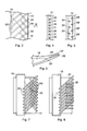
- Figures 2 to 4 show cooling passages 28 and 30 corresponding to the passages 20 of Figure 1 and Figure 1A but disposed in accordance with the present invention.
- the passages 28 are disposed in a first array
- the passages 30 are disposed in a second array.
- the passages 28 of the first array are inclined at 45° to the trailing edge 10 of the blade
- the passages 30 of the second array are inclined at 135° to the trailing edge 10, the angle being measured in the same direction as that of the passages 28 of the first array.
- the passages 28, 30 lie in a common plane and the result of this is that the passages 30 intersect the passages 28 at right angles as shown in Figure 3.
- the passages 28, 30 open at discharge openings 29, 31 respectively.
- each passage 28 of the first array extends the full distance from the supply passage 18 to the trailing edge 10, at least over the major part of the airfoil portion 2 of the blade.
- the passages 30 of the second array do not reach the supply passage 18. Instead, they terminate at a position which, as shown in Figure 3, is approximately halfway between the supply passage and the trailing edge 10.
- there is a first region of the blade adjacent the supply passage 18 that is occupied solely by the passages 28 of the first array.
- a second region of the blade, extending from the first region to the discharge openings 29, 31, is occupied by passages 28, 30 of both the first and second arrays.
- cooling air admitted to the supply passage 18 can reach the cooling passages 30 of the second array only after passing initially through the cooling passages 28 of the first array.
- the air flow divides so that air can reach the discharge ports 29 and 31 by many different routes.
- the passages 28' of the first array and the passages 30' of the second array may not be entirely coplanar. As shown in Figure 6, they are offset so that their centrelines lie in respective planes which are parallel to each other. Nevertheless, the cooling passages 30' still intersect the cooling passages 28' so that, in use, the flow of cooling air between the two remains possible. Although, in the embodiment of Figures 5 and 6, the two arrays of cooling passages 28', 30' lie in parallel planes, they could lie in planes which are slightly inclined to each other, provided that each cooling passage 30' intersects, at least partially, at least one of the cooling passages 28'.
- FIG 8 corresponds to Figure 7, but shows an embodiment in which the cooling passages 30 of the second array extend perpendicular to the trailing edge 10 instead of obliquely, as shown in Figure 7.
- the cooling passages 28 of the first array may also be oriented at a different angle from that shown in Figure 7, it being important only that the cooling passages 28, 30 are differently inclined with respect to the trailing edge, so that they intersect.
- the cooling passages 30, although they stop short of the supply passage 18, are oriented so that their centrelines, exemplified by the centreline 32, when projected, intersect the supply passage 18.
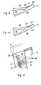
- the discharge openings 29" and 31" emerge on one of the flow surfaces, in this case the pressure face 34, of the air foil portion 2 of the blade.
- the cooling passages 30" of the second array lie in a plane which is parallel to that of the cooling passages 28" of the first array, but lying nearer the pressure face 38.
- the cooling passages 30" of the second array lie further from the pressure face 34 than those of the first array.
- Figure 11 shows a diagrammatic perspective view of an embodiment corresponding to Figures 9 and 10, illustrating the shape of the discharge openings 29" and 31" as they emerge at the pressure face 34. It will be appreciated that, in this embodiment, the emerging air flows over the pressure face 34 towards the trailing edge 12, so providing film cooling at this region of the blade.
- the discharge openings 29" and 31" emerge on the trailing edge 12 and pressure face 34 respectively.
- the discharge openings 29" and 31" emerge on the pressure face 34.
- the cooling passages 30" stop short of the supply passage 18 and their centre lines 32", when projected, do not intersect the supply passage 18.
- the air emerging from discharge openings 31" shows over the pressure face 34 towards the trailing edge 12, so providing film cooling at this region of the blade.
- heat transfer from the material of the blade to the cooling air passing through the passages 28 of the first array is relatively high, but decreases along the cooling passages 28 owing to boundary layer effects.
- new boundary layers form, and so the heat transfer increases again.
- manufacture of the cooling passage arrangement as described above is simpler than for an arrangement in which all of the passages, including passages corresponding to the passages 30 of the second array, open into the supply passage 18.
Landscapes
- Engineering & Computer Science (AREA)
- Mechanical Engineering (AREA)
- General Engineering & Computer Science (AREA)
- Turbine Rotor Nozzle Sealing (AREA)
Abstract

Description
- This arrangement relates to a component having a cooling arrangement, and is particularly, although not exclusively, concerned with an airfoil component, such as a turbine blade, for a gas turbine engine.
- The gas flow over the components of a turbine stage in a gas turbine engine is often at a temperature which exceeds the melting point of the materials from which the components are made. Measures are therefore taken to cool these components, for example by feeding air from the compressor stage of the engine to interior passageways within the components, the air emerging at openings in the surface of the components to form a film of cooler air to protect the components from the hot gases.
- US 3819295 discloses a turbine blade having a supply passage for cooling air and two sets of cooling passages which extend from the supply passage to the exterior of the blade. Cooling passages of one set extend obliquely to and intersect the cooling passages of the other set. A problem with a cooling arrangement of this kind is that the resistance to air flow through the cooling passages can vary widely depending on how accurately the cooling passages are aligned. The minimum resistance to air flow, and consequently the maximum flow of cooling air through the cooling passages is achieved when the cooling passages only just intersect. As the distance between the centrelines of intersecting cooling passages decreases, so the overall flow cross-sections become smaller, reducing the air flow rate through the cooling passages. Since the cooling passages are of very small diameter, it is very difficult to achieve sufficient manufacturing accuracy to achieve strictly coplanar sets of cooling passages. Consequently, the cooling air flow rate through the cooling passages is unpredictable, and can vary significantly from blade to blade.
- According to the present invention there is provided a component for a gas turbine engine having a cooling arrangement comprising:
- a supply passage within the component;
- a plurality of cooling passages which open at respective discharge openings at a surface of the component,
- a first region of the component adjacent the supply passage that is provided with a first array of cooling passages which lie in a common plane, each cooling passage of the first array opening into the supply passage at its end away from its discharge opening, and
- a second region of the component extending from the first region to the discharge openings comprising a second array of cooling passages which lie in a common plane and the first array of cooling passages,
- each of the cooling passages of the second array intersect at least one of the cooling passages of the first array, each of the cooling passages of the second array terminating short of the supply passage at its end away from its discharge opening at an intersection with at least one of the cooling passages of the first array.
- As a result of this arrangement, all air entering the cooling passages from the supply passage flows first through the cooling passages of the first array before encountering intersections with the cooling passages of the second array. A result of this is that the portions of the cooling passages of the first array nearest the supply passage provide the greater part of the restriction to flow of the cooling air from the supply passage to the discharge openings. The flow restriction is dependent on the diameter of each cooling passage, and this can be achieved with accuracy, so providing a predictable flow rate of cooling air.
- In this specification, references to the cooling passages of the first and second arrays being in a common plane are not restricted to embodiments in which the common planes are flat. The planes may be curved about one or more axes, particularly if the component is an airfoil which may, for example, have a tangential lean in the radially outwards direction.
- The common planes of the first and second arrays may be coincident, but in some embodiments they are displaced from one another, for example they may be parallel to each other or inclined to each other.
- If the component is an airfoil component, such as a turbine blade of a gas turbine engine, the discharge openings of the cooling passages of at least one of the arrays may be situated at the trailing edge of the blade. Alternatively, the discharge openings of the cooling passages of at least one of the arrays may be positioned away from the trailing edge, for example on the pressure face of the blade.
- The cooling passages of each array may be parallel to each other. The cooling passages of the first array may be inclined by, for example, 30° to 60° to the trailing edge of the blade, and those of the second array may be inclined at, for example, 90° to 150°, for example 120° to 150°, to the trailing edge.
- In a preferred embodiment, the cooling passages of the second array terminate at a distance from their discharge openings, measured perpendicular to the trailing edge of the blade, which is not less than ¼ and not more than ¾ of the total distance between the discharge openings of those coolant passages and the supply passage.
- Each cooling passage of the second array may intersect only one coolant passage of the first array but in some embodiments the coolant passages of the second array intersect at least three cooling passages of the first array.
- For a better understanding of the present invention, and to show more clearly how it may be carried into effect, reference will now be made, by way of example, to the accompanying drawings, in which:-
- Figure 1 is a cut-away view of a known turbine blade having two cooling air supply passages;
- Figure 1A is a cut-away view of known turbine blade having a single cooling air supply passage;
- Figure 2 is a partly sectioned end view of a turbine blade in accordance with the present invention;
- Figure 3 is a diagrammatic sectional view corresponding to the section indicated by the line III-III in Figure 2;
- Figure 4 is a view in the direction of the arrow IV in Figure 2 and Figure 3;
- Figure 5 corresponds to Figure 4 but shows an alternative embodiment;
- Figure 6 correspond to Figure 2 but shows the embodiment of Figure 5;
- Figures 7 and 8 correspond to Figure 3 but show alternative configurations;
- Figures 9 and 10 correspond to Figure 6 but show alternative embodiments;
- Figure 11 is a partial perspective view corresponding to Figure 9 and Figure 10; and
- Figure 12 and Figure 13 correspond to Figure 6 but show alternative embodiments.
- The turbine blade shown in Figure 1 comprises an
airfoil section 2 having abase 4 including afir tree root 6 at one end and atip structure 8 at the other end. Theairfoil section 2 has a leadingedge 10 and atrailing edge 12. Within the blade, there are two cooling arrangements comprising a highpressure supply passage 14 which receives air from the high pressure compressor of the engine to which the blade is fitted. The high pressure supply passage follows a serpentine route within the blade, beginning near the leadingedge 10 of the blade, with the air emerging at the surface of the blade throughdischarge orifices 16. - A low
pressure supply passage 18 is provided nearer thetrailing edge 12 of theairfoil portion 2. This supply passage receives air from the low pressure compressor of the engine. Cooling air from the lowpressure supply passage 18 reaches the exterior of the blade through cooling passages formed in the blade, includingcooling passages 20 which extend between thesupply passage 18 anddischarge openings 22 at the trailing edge of theairfoil portion 2.Other discharge openings 24 are provided in the pressure face of theairfoil portion tip structure 8. - Alternatively, as shown in Figure 1A, the blade is provided with a
single cooling passage 18 which follows a serpentine route within the blade and supplies all thedischarge orifices 16,cooling passages 20 anddischarge openings - Figures 2 to 4
show cooling passages passages 20 of Figure 1 and Figure 1A but disposed in accordance with the present invention. As can be appreciated from Figure 3, thepassages 28 are disposed in a first array, and thepassages 30 are disposed in a second array. In the specific embodiment shown in Figure 3, which is also represented in diagrammatic form in Figure 7, thepassages 28 of the first array are inclined at 45° to thetrailing edge 10 of the blade whereas thepassages 30 of the second array are inclined at 135° to thetrailing edge 10, the angle being measured in the same direction as that of thepassages 28 of the first array. - As can be appreciated from Figure 4, the
passages passages 30 intersect thepassages 28 at right angles as shown in Figure 3. At thetrailing edge 10 of the blade, thepassages discharge openings - It will be appreciated that each
passage 28 of the first array extends the full distance from thesupply passage 18 to thetrailing edge 10, at least over the major part of theairfoil portion 2 of the blade. However, thepassages 30 of the second array do not reach thesupply passage 18. Instead, they terminate at a position which, as shown in Figure 3, is approximately halfway between the supply passage and thetrailing edge 10. Put another way, there is a first region of the blade adjacent thesupply passage 18 that is occupied solely by thepassages 28 of the first array. A second region of the blade, extending from the first region to thedischarge openings passages supply passage 18 can reach thecooling passages 30 of the second array only after passing initially through thecooling passages 28 of the first array. At the junctions between thecooling passages 28 and thecooling passages 30, the air flow divides so that air can reach thedischarge ports - Because all of the air flow passes initially along the
cooling passages 28, it is the flow cross-section of these passages which determines the overall flow rate of cooling air from thesupply passage 18 to thedischarge orifices passages 28 can be formed with considerable accuracy, the overall flow rate through thepassages - In an alternative embodiment, as represented diagrammatically in Figures 5 and 6, the passages 28' of the first array and the passages 30' of the second array may not be entirely coplanar. As shown in Figure 6, they are offset so that their centrelines lie in respective planes which are parallel to each other. Nevertheless, the cooling passages 30' still intersect the cooling passages 28' so that, in use, the flow of cooling air between the two remains possible. Although, in the embodiment of Figures 5 and 6, the two arrays of cooling passages 28', 30' lie in parallel planes, they could lie in planes which are slightly inclined to each other, provided that each cooling passage 30' intersects, at least partially, at least one of the cooling passages 28'.
- Figure 8 corresponds to Figure 7, but shows an embodiment in which the
cooling passages 30 of the second array extend perpendicular to the trailingedge 10 instead of obliquely, as shown in Figure 7. It will be appreciated that thecooling passages 28 of the first array may also be oriented at a different angle from that shown in Figure 7, it being important only that thecooling passages cooling passages 30, although they stop short of thesupply passage 18, are oriented so that their centrelines, exemplified by thecentreline 32, when projected, intersect thesupply passage 18. - In the embodiments of Figures 9 to 11, the
discharge openings 29" and 31" emerge on one of the flow surfaces, in this case thepressure face 34, of theair foil portion 2 of the blade. In the embodiment of Figure 9, thecooling passages 30" of the second array lie in a plane which is parallel to that of thecooling passages 28" of the first array, but lying nearer the pressure face 38. By contrast, in the embodiment of Figure 10, thecooling passages 30" of the second array lie further from thepressure face 34 than those of the first array. - Figure 11 shows a diagrammatic perspective view of an embodiment corresponding to Figures 9 and 10, illustrating the shape of the
discharge openings 29" and 31" as they emerge at thepressure face 34. It will be appreciated that, in this embodiment, the emerging air flows over thepressure face 34 towards the trailingedge 12, so providing film cooling at this region of the blade. - In the embodiment of Figure 12 the
discharge openings 29" and 31" emerge on the trailingedge 12 and pressure face 34 respectively. In the embodiment of Figure 13 thedischarge openings 29" and 31" emerge on thepressure face 34. In both embodiments thecooling passages 30" stop short of thesupply passage 18 and theircentre lines 32", when projected, do not intersect thesupply passage 18. The air emerging fromdischarge openings 31" shows over thepressure face 34 towards the trailingedge 12, so providing film cooling at this region of the blade. - In use, heat transfer from the material of the blade to the cooling air passing through the
passages 28 of the first array is relatively high, but decreases along thecooling passages 28 owing to boundary layer effects. At each intersection between thecooling passages 28 and thecooling passages 30 of the second array, new boundary layers form, and so the heat transfer increases again. Thus, the embodiments described above enable effective heat transfer between thesupply passage 18 and the trailing edge 10 (or thedischarge openings 29", 31" in the embodiments of Figures 9 to 13) while achieving a fixed flow array along thepassages passages - If the two arrays of
cooling passages cooling passages - Furthermore, manufacture of the cooling passage arrangement as described above is simpler than for an arrangement in which all of the passages, including passages corresponding to the
passages 30 of the second array, open into thesupply passage 18.
Claims (18)
- An aerofoil component for a gas turbine engine having a cooling arrangement comprising:a supply passage (18) within the component;a plurality of cooling passages (28) which open at respective discharge openings (29,31) at a surface of the component,a first region of the component adjacent the supply passage (18) that is provided with a first array of cooling passages (28) which lie in a common plane, each cooling passage (28) of the first array opening into the supply passage (18) at its end away from its discharge opening (29), anda second region of the component extending from the first region to the discharge openings (29,31) comprising a second array of cooling passages (30) which lie in a common plane and the first array of cooling passages,each of the cooling passages (30) of the second array intersect at least one of the cooling passages (28) of the first array, each of the cooling passages of the second array (30) terminating short of the supply passage (18) at its end away from its discharge opening (31) at an intersection with at least one of the cooling passages (28) of the first array.
- A component as claimed in claim 1 in which the projected centre lines (32) of at least some of the cooling passages (30) of the second array intersect the supply passage (18).
- A component as claimed in claim 1 in which none of the projected centre lines (32) of the cooling passages (30) of the second array intersect the supply passage (18).
- A component as claimed in claim 1, claim 2 or claim 3, in which the cooling passages of the first array (28) and the cooling passages (30) of the second array lie in the same common plane.
- A component as claimed in claim 1, claim 2 or claim 3, in which the cooling passages (28) of the first array and the cooling passages (30) of the second array lie in respective different common planes.
- A component as claimed in claim 5, in which the common planes are parallel to each other.
- A component as claimed in claim 5, in which the common planes are inclined to each other.
- A component as claimed in claim 1, in which at least one of the common planes is curved.
- A component as claimed in claim 1, which is an airfoil component for a gas turbine engine.
- A component as claimed in claim 9, which is a turbine blade.
- A turbine blade as claimed in claim 10, in which the discharge openings (29,31) of the cooling passages (28,33) of at least one of the arrays are provided at the trailing edge (12) of the turbine blade.
- A turbine blade as claimed in claim 10, in which the discharge openings (29,31) of the cooling passages of at least one of the arrays are provided at positions away from the trailing edge (12) of the blade.
- A turbine blade as claimed in claim 12, in which the discharge openings (29,31) are situated in a pressure face (34) of the turbine blade.
- A turbine blade as claimed in any one of claims 10 to 13, in which the cooling passages (28) of the first array are disposed at an angle of not less than 30° and not more than 60° with respect to the trailing edge (10) of the turbine blade.
- A turbine blade as claimed in any one of claims 10 to 14, in which the cooling passages of the second array (30) are disposed at angle of not less than 90° and not more than 150° to the trailing edge (12) of the turbine blade.
- A turbine blade as claimed in claim 15, in which the cooling passages (30) of the second array are disposed at angle of not less 120° and not more than 150° to the trailing edge (12) of the turbine blade.
- A turbine blade as claimed in any one of claims 10 to 16, in which the cooling passages (30) of the second array terminate at a distance from their discharge openings (31) which is not less than ¼ and not more than ¾ of the distance from the discharge openings (29,31) to the supply passage (18).
- A component as claimed in any one of the preceding claims,, in which each of the cooling passages (28) of the first array intersects at least three cooling passages (30) of the second array.
Applications Claiming Priority (1)
| Application Number | Priority Date | Filing Date | Title |
|---|---|---|---|
| GB0418743A GB2417295B (en) | 2004-08-21 | 2004-08-21 | A component having a cooling arrangement |
Publications (3)
| Publication Number | Publication Date |
|---|---|
| EP1627991A2 true EP1627991A2 (en) | 2006-02-22 |
| EP1627991A3 EP1627991A3 (en) | 2008-06-25 |
| EP1627991B1 EP1627991B1 (en) | 2009-11-25 |
Family
ID=33042478
Family Applications (1)
| Application Number | Title | Priority Date | Filing Date |
|---|---|---|---|
| EP05254749A Ceased EP1627991B1 (en) | 2004-08-21 | 2005-07-29 | A component having a cooling arrangement |
Country Status (4)
| Country | Link |
|---|---|
| US (1) | US7438528B2 (en) |
| EP (1) | EP1627991B1 (en) |
| DE (1) | DE602005017857D1 (en) |
| GB (1) | GB2417295B (en) |
Cited By (3)
| Publication number | Priority date | Publication date | Assignee | Title |
|---|---|---|---|---|
| EP1992784A3 (en) * | 2007-05-18 | 2014-07-09 | Rolls-Royce plc | Cooling arrangement |
| EP3179039A1 (en) * | 2015-12-11 | 2017-06-14 | Rolls-Royce plc | Component for a gas turbine engine |
| EP2372092A3 (en) * | 2010-03-31 | 2018-01-10 | General Electric Company | Internal cooling channels for industrial machines |
Families Citing this family (7)
| Publication number | Priority date | Publication date | Assignee | Title |
|---|---|---|---|---|
| US7775768B2 (en) * | 2007-03-06 | 2010-08-17 | United Technologies Corporation | Turbine component with axially spaced radially flowing microcircuit cooling channels |
| US8210798B2 (en) | 2008-02-13 | 2012-07-03 | United Technologies Corporation | Cooled pusher propeller system |
| US8113784B2 (en) * | 2009-03-20 | 2012-02-14 | Hamilton Sundstrand Corporation | Coolable airfoil attachment section |
| US9422816B2 (en) * | 2009-06-26 | 2016-08-23 | United Technologies Corporation | Airfoil with hybrid drilled and cutback trailing edge |
| US10060264B2 (en) * | 2010-12-30 | 2018-08-28 | Rolls-Royce North American Technologies Inc. | Gas turbine engine and cooled flowpath component therefor |
| US20160341046A1 (en) * | 2014-05-29 | 2016-11-24 | General Electric Company | Dust holes |
| US10563519B2 (en) * | 2018-02-19 | 2020-02-18 | General Electric Company | Engine component with cooling hole |
Citations (3)
| Publication number | Priority date | Publication date | Assignee | Title |
|---|---|---|---|---|
| US3819295A (en) | 1972-09-21 | 1974-06-25 | Gen Electric | Cooling slot for airfoil blade |
| US5326224A (en) | 1991-03-01 | 1994-07-05 | General Electric Company | Cooling hole arrangements in jet engine components exposed to hot gas flow |
| US5511946A (en) | 1994-12-08 | 1996-04-30 | General Electric Company | Cooled airfoil tip corner |
Family Cites Families (7)
| Publication number | Priority date | Publication date | Assignee | Title |
|---|---|---|---|---|
| US4203706A (en) * | 1977-12-28 | 1980-05-20 | United Technologies Corporation | Radial wafer airfoil construction |
| US5403158A (en) * | 1993-12-23 | 1995-04-04 | United Technologies Corporation | Aerodynamic tip sealing for rotor blades |
| FR2715693B1 (en) * | 1994-02-03 | 1996-03-01 | Snecma | Fixed or mobile turbine-cooled blade. |
| US5498133A (en) * | 1995-06-06 | 1996-03-12 | General Electric Company | Pressure regulated film cooling |
| GB2310896A (en) * | 1996-03-05 | 1997-09-10 | Rolls Royce Plc | Air cooled wall |
| US6422819B1 (en) * | 1999-12-09 | 2002-07-23 | General Electric Company | Cooled airfoil for gas turbine engine and method of making the same |
| US6325593B1 (en) * | 2000-02-18 | 2001-12-04 | General Electric Company | Ceramic turbine airfoils with cooled trailing edge blocks |
-
2004
- 2004-08-21 GB GB0418743A patent/GB2417295B/en not_active Expired - Fee Related
-
2005
- 2005-07-29 EP EP05254749A patent/EP1627991B1/en not_active Ceased
- 2005-07-29 DE DE602005017857T patent/DE602005017857D1/en not_active Expired - Lifetime
- 2005-08-09 US US11/199,180 patent/US7438528B2/en not_active Expired - Fee Related
Patent Citations (3)
| Publication number | Priority date | Publication date | Assignee | Title |
|---|---|---|---|---|
| US3819295A (en) | 1972-09-21 | 1974-06-25 | Gen Electric | Cooling slot for airfoil blade |
| US5326224A (en) | 1991-03-01 | 1994-07-05 | General Electric Company | Cooling hole arrangements in jet engine components exposed to hot gas flow |
| US5511946A (en) | 1994-12-08 | 1996-04-30 | General Electric Company | Cooled airfoil tip corner |
Cited By (3)
| Publication number | Priority date | Publication date | Assignee | Title |
|---|---|---|---|---|
| EP1992784A3 (en) * | 2007-05-18 | 2014-07-09 | Rolls-Royce plc | Cooling arrangement |
| EP2372092A3 (en) * | 2010-03-31 | 2018-01-10 | General Electric Company | Internal cooling channels for industrial machines |
| EP3179039A1 (en) * | 2015-12-11 | 2017-06-14 | Rolls-Royce plc | Component for a gas turbine engine |
Also Published As
| Publication number | Publication date |
|---|---|
| EP1627991A3 (en) | 2008-06-25 |
| GB0418743D0 (en) | 2004-09-22 |
| US20060039787A1 (en) | 2006-02-23 |
| GB2417295B (en) | 2006-10-25 |
| DE602005017857D1 (en) | 2010-01-07 |
| US7438528B2 (en) | 2008-10-21 |
| EP1627991B1 (en) | 2009-11-25 |
| GB2417295A (en) | 2006-02-22 |
Similar Documents
| Publication | Publication Date | Title |
|---|---|---|
| US6602052B2 (en) | Airfoil tip squealer cooling construction | |
| US7572103B2 (en) | Component comprising a multiplicity of cooling passages | |
| US7997868B1 (en) | Film cooling hole for turbine airfoil | |
| US5382133A (en) | High coverage shaped diffuser film hole for thin walls | |
| CA1275052A (en) | Convergent-divergent film coolant passage | |
| EP2547871B1 (en) | Gas turbine airfoil with shaped trailing edge coolant ejection holes and corresponding turbine | |
| EP1108856B1 (en) | Turbine nozzle with sloped film cooling hole rows | |
| US5246341A (en) | Turbine blade trailing edge cooling construction | |
| CA1273583A (en) | Coolant passages with full coverage film cooling slot | |
| US10436040B2 (en) | Airfoil with dual-wall cooling for a gas turbine engine | |
| EP1055800B1 (en) | Turbine airfoil with internal cooling | |
| US8814500B1 (en) | Turbine airfoil with shaped film cooling hole | |
| US8052390B1 (en) | Turbine airfoil with showerhead cooling | |
| JPS62165502A (en) | Wall cooled in aerofoil | |
| US20060073015A1 (en) | Gas turbine airfoil film cooling hole | |
| GB2402715A (en) | Gas turbine aerofoil with leading edge impingement cooling | |
| EP1865152B1 (en) | Cooling microcircuits for turbine airfoils | |
| US20090126335A1 (en) | Cooling structure | |
| US7300252B2 (en) | Gas turbine airfoil leading edge cooling construction | |
| JPS62165504A (en) | Wall cooled in aerofoil | |
| JP2006144800A (en) | Airfoil with auxiliary cooling channel and gas turbine engine including the same | |
| US7438528B2 (en) | Component having a cooling arrangement | |
| EP2103781B1 (en) | Full coverage trailing edge microcircuit with alternating converging exits | |
| US7311498B2 (en) | Microcircuit cooling for blades | |
| US8545180B1 (en) | Turbine blade with showerhead film cooling holes |
Legal Events
| Date | Code | Title | Description |
|---|---|---|---|
| PUAI | Public reference made under article 153(3) epc to a published international application that has entered the european phase |
Free format text: ORIGINAL CODE: 0009012 |
|
| AK | Designated contracting states |
Kind code of ref document: A2 Designated state(s): AT BE BG CH CY CZ DE DK EE ES FI FR GB GR HU IE IS IT LI LT LU LV MC NL PL PT RO SE SI SK TR |
|
| AX | Request for extension of the european patent |
Extension state: AL BA HR MK YU |
|
| PUAL | Search report despatched |
Free format text: ORIGINAL CODE: 0009013 |
|
| AK | Designated contracting states |
Kind code of ref document: A3 Designated state(s): AT BE BG CH CY CZ DE DK EE ES FI FR GB GR HU IE IS IT LI LT LU LV MC NL PL PT RO SE SI SK TR |
|
| AX | Request for extension of the european patent |
Extension state: AL BA HR MK YU |
|
| 17P | Request for examination filed |
Effective date: 20080822 |
|
| 17Q | First examination report despatched |
Effective date: 20081002 |
|
| AKX | Designation fees paid |
Designated state(s): DE FR |
|
| GRAP | Despatch of communication of intention to grant a patent |
Free format text: ORIGINAL CODE: EPIDOSNIGR1 |
|
| GRAS | Grant fee paid |
Free format text: ORIGINAL CODE: EPIDOSNIGR3 |
|
| GRAA | (expected) grant |
Free format text: ORIGINAL CODE: 0009210 |
|
| AK | Designated contracting states |
Kind code of ref document: B1 Designated state(s): DE FR |
|
| REF | Corresponds to: |
Ref document number: 602005017857 Country of ref document: DE Date of ref document: 20100107 Kind code of ref document: P |
|
| PLBE | No opposition filed within time limit |
Free format text: ORIGINAL CODE: 0009261 |
|
| STAA | Information on the status of an ep patent application or granted ep patent |
Free format text: STATUS: NO OPPOSITION FILED WITHIN TIME LIMIT |
|
| 26N | No opposition filed |
Effective date: 20100826 |
|
| REG | Reference to a national code |
Ref country code: FR Ref legal event code: PLFP Year of fee payment: 12 |
|
| REG | Reference to a national code |
Ref country code: FR Ref legal event code: CA Effective date: 20170517 |
|
| REG | Reference to a national code |
Ref country code: FR Ref legal event code: PLFP Year of fee payment: 13 |
|
| REG | Reference to a national code |
Ref country code: FR Ref legal event code: PLFP Year of fee payment: 14 |
|
| PGFP | Annual fee paid to national office [announced via postgrant information from national office to epo] |
Ref country code: FR Payment date: 20190725 Year of fee payment: 15 Ref country code: DE Payment date: 20190729 Year of fee payment: 15 |
|
| REG | Reference to a national code |
Ref country code: DE Ref legal event code: R119 Ref document number: 602005017857 Country of ref document: DE |
|
| PG25 | Lapsed in a contracting state [announced via postgrant information from national office to epo] |
Ref country code: FR Free format text: LAPSE BECAUSE OF NON-PAYMENT OF DUE FEES Effective date: 20200731 |
|
| PG25 | Lapsed in a contracting state [announced via postgrant information from national office to epo] |
Ref country code: DE Free format text: LAPSE BECAUSE OF NON-PAYMENT OF DUE FEES Effective date: 20210202 |