EP1627809A2 - Bicycle disk brake rotor with laminated components having differing thicknesses - Google Patents
Bicycle disk brake rotor with laminated components having differing thicknesses Download PDFInfo
- Publication number
- EP1627809A2 EP1627809A2 EP05015696A EP05015696A EP1627809A2 EP 1627809 A2 EP1627809 A2 EP 1627809A2 EP 05015696 A EP05015696 A EP 05015696A EP 05015696 A EP05015696 A EP 05015696A EP 1627809 A2 EP1627809 A2 EP 1627809A2
- Authority
- EP
- European Patent Office
- Prior art keywords
- rotor member
- rotor
- brake
- members
- thickness
- Prior art date
- Legal status (The legal status is an assumption and is not a legal conclusion. Google has not performed a legal analysis and makes no representation as to the accuracy of the status listed.)
- Withdrawn
Links
Images


Classifications
-
- F—MECHANICAL ENGINEERING; LIGHTING; HEATING; WEAPONS; BLASTING
- F16—ENGINEERING ELEMENTS AND UNITS; GENERAL MEASURES FOR PRODUCING AND MAINTAINING EFFECTIVE FUNCTIONING OF MACHINES OR INSTALLATIONS; THERMAL INSULATION IN GENERAL
- F16D—COUPLINGS FOR TRANSMITTING ROTATION; CLUTCHES; BRAKES
- F16D65/00—Parts or details
- F16D65/02—Braking members; Mounting thereof
- F16D65/12—Discs; Drums for disc brakes
-
- B—PERFORMING OPERATIONS; TRANSPORTING
- B62—LAND VEHICLES FOR TRAVELLING OTHERWISE THAN ON RAILS
- B62L—BRAKES SPECIALLY ADAPTED FOR CYCLES
- B62L1/00—Brakes; Arrangements thereof
- B62L1/005—Brakes; Arrangements thereof constructional features of brake elements, e.g. fastening of brake blocks in their holders
-
- F—MECHANICAL ENGINEERING; LIGHTING; HEATING; WEAPONS; BLASTING
- F16—ENGINEERING ELEMENTS AND UNITS; GENERAL MEASURES FOR PRODUCING AND MAINTAINING EFFECTIVE FUNCTIONING OF MACHINES OR INSTALLATIONS; THERMAL INSULATION IN GENERAL
- F16D—COUPLINGS FOR TRANSMITTING ROTATION; CLUTCHES; BRAKES
- F16D65/00—Parts or details
- F16D65/02—Braking members; Mounting thereof
- F16D2065/13—Parts or details of discs or drums
- F16D2065/1304—Structure
- F16D2065/132—Structure layered
-
- F—MECHANICAL ENGINEERING; LIGHTING; HEATING; WEAPONS; BLASTING
- F16—ENGINEERING ELEMENTS AND UNITS; GENERAL MEASURES FOR PRODUCING AND MAINTAINING EFFECTIVE FUNCTIONING OF MACHINES OR INSTALLATIONS; THERMAL INSULATION IN GENERAL
- F16D—COUPLINGS FOR TRANSMITTING ROTATION; CLUTCHES; BRAKES
- F16D2200/00—Materials; Production methods therefor
- F16D2200/0004—Materials; Production methods therefor metallic
- F16D2200/0008—Ferro
- F16D2200/0017—Ferro corrosion-resistant
-
- F—MECHANICAL ENGINEERING; LIGHTING; HEATING; WEAPONS; BLASTING
- F16—ENGINEERING ELEMENTS AND UNITS; GENERAL MEASURES FOR PRODUCING AND MAINTAINING EFFECTIVE FUNCTIONING OF MACHINES OR INSTALLATIONS; THERMAL INSULATION IN GENERAL
- F16D—COUPLINGS FOR TRANSMITTING ROTATION; CLUTCHES; BRAKES
- F16D2200/00—Materials; Production methods therefor
- F16D2200/0004—Materials; Production methods therefor metallic
- F16D2200/0026—Non-ferro
- F16D2200/003—Light metals, e.g. aluminium
Definitions
- the present invention is directed to bicycles and, more particularly, to a bicycle disk brake rotor.
- Conventional bicycle disk brake devices comprise a disk rotor that rotates with the bicycle wheel, and calipers with brake pads that frictionally contact the disk rotor to slow or stop the wheel.
- the disk rotor may be a metal member that comprises a mounting member and a ring-shaped rotor member fixed to the mounting member, wherein the mounting member is structured to be mounted to the bicycle wheel hub. Since bicycles are propelled by human power, reducing the weight of the bicycle components is an important objective of many bicycle manufacturers. This includes reducing the weight of disk brake devices. On the other hand, it is also desirable to resist rotor wear caused by friction with the brake pads while providing proper heat dissipation.
- That disk rotor comprises an annular aluminum first rotor member sandwiched between a pair of annular stainless steel second rotor members.
- the stainless steel second rotor members provide wear resistance, while the aluminum first rotor member provides heat dissipation.
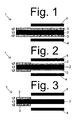
- Fig. 1 is a schematic diagram of a known disk rotor 1, not necessarily in the prior art, that resembles the disk rotor disclosed in JP 2,679,162.
- This rotor comprises a first rotor member 2 sandwiched between a pair of second rotor members 3, wherein a pair of brake pads 4 contact respective outer surfaces of the second rotor members 3 during use.
- the thicknesses t2 of the second rotor members 3 typically are the same to simplify manufacturing.
- the second rotor members 3 typically wear evenly during use as shown in Fig. 2.
- the brake pads 4 completely wear away the second rotor members 3 as shown in Fig. 3.
- braking effectiveness decreases significantly. The rider readily notices such reduced braking effectiveness and usually considers it unacceptable.
- a bicycle disk brake rotor apparatus comprises a first rotor member, a second rotor member, and a third rotor member, wherein the first rotor member is attached to and is disposed between the second rotor member and the third rotor member.
- a thickness of the second rotor member is different from a thickness of the third rotor member.
- Fig. 4 is a side view of a bicycle 10 with a particular embodiment of a complete disk brake apparatus 12
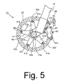
- Fig. 5 is a side view of disk brake apparatus 12.
- Bicycle 10 is a conventional one with a frame 14 supporting a handlebar 15, front and rear forks 16 (only the front fork is shown), front and rear wheels 17 (only the front wheel is shown), and a drive device comprising a sprocket and chain (not shown). Since the structure of such a conventional bicycle is well known in the field, further description if its structure shall be omitted.
- Disk brake apparatus 12 comprises a brake caliper 21 mounted on front fork 16, a brake rotor 22 attached to a hub 17a of front wheel 17 so that brake rotor 22 rotates integrally with front wheel 17, and a brake operating mechanism 23.
- Brake caliper 21 is attached to front fork 16 near brake rotor 22, and it applies a frictional force to brake rotor 22 in response to the operation of brake operating mechanism 23 to stop the rotation of brake rotor 22 and front wheel 17.
- brake caliper 21 comprises a housing 50 and a piston unit 51.
- Housing 50 is constructed of a thermally conducting material such as an aluminum alloy, and it comprises a first housing member 52a and a second housing member 52b bolted together in a conventional manner to form a slot to receive brake rotor 22 therebetween.
- Housing members 52a and 52b have substantially the same shape, except that hydraulic tubing 86 for brake operating mechanism 23 is connected to second housing member 52b to supply brake oil to both housing members 52a and 52b.
- Second housing member 52b also has an outwardly extending flange that forms an attachment member 54 for bolting brake caliper 21 to front fork 16.
- piston unit 51 comprises four pistons 74 and a pair of brake pads 76.
- Pistons 74 slidably fit into round cylinders 57a and 57b formed in housing members 52a and 52b so as to move between a brake release position and a braking position.
- Brake pads 76 move integrally with pistons 74.
- the brake pads 76 When pistons 74 move from the brake release position to the braking position, the brake pads 76 also move from the brake release position to the braking position.
- brake pads 76 press against and apply a frictional force to brake rotor 22 to thereby decrease or stop rotation of brake rotor 22 and front wheel 17.
- the brake pads 76 are spaced apart from brake rotor 22, thus allowing brake rotor 22 and front wheel 17 to freely rotate.
- Brake operating mechanism 23 comprises a brake lever assembly 80, a master cylinder 81, a piston 82, and an operating fluid tank 83.
- Brake lever assembly 80 comprises a bracket 84 mounted on handlebar 15 and a lever component 85 pivotably mounted on bracket 84.
- Bracket 84 is integrally formed with master cylinder 81, and piston 82 and operating fluid tank 83 are supported by bracket 84.
- Piston 82 is slidingly disposed within master cylinder 81, and operating fluid tank 83 is in fluid communication with master cylinder 81.
- One end of piston 82 is connected to lever component 85 so that piston 82 reciprocates inside master cylinder 81 in response to the pulling and releasing of lever component 85.
- Pulling lever component 85 causes pressurized oil to move through the hydraulic tubing 86 connected to brake caliper 21, the pressurized oil moves pistons 74, brake pads 76 contact and apply frictional force to brake rotor 22, and the front wheel 17 is braked.
- brake rotor 22 comprises a centrally disposed hub mounting member 22a attached to hub 17a, a ring-shaped rotor member 22b for contacting brake pads 76, and a plurality of fixing pins 22c that fix rotor member 22b to hub mounting member 22a.
- hub mounting member 22a is constructed of an aluminum alloy and comprises a centrally disposed cylindrical hub attachment component 40 and a rotor attachment component 41.
- Hub attachment component 40 is attached to hub 17a through a splined component 40a, and rotor attachment component 41 extends radially outwardly from hub attachment component 41. More specifically, rotor attachment component 41 has five arm components 41a extending radially outwardly from hub attachment component 40.
- a fixing hole 41b for fixing hub attachment component 41 to rotor member 22b is formed at the tip of each arm component 41 a.
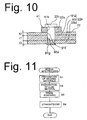
- rotor member 22b may be a laminated structure comprising a first rotor member 90 sandwiched between a second rotor member 91a and a third rotor member 91b.
- First rotor member 90 may be formed from aluminum, which has a relatively high thermal conductivity
- second and third rotor members 91a and 91b may be formed from stainless steel, which has higher braking wear resistance than aluminum but less thermal conductivity than aluminum.
- the second and third rotor members 91a and 91b may be press welded to opposite sides of first rotor member 90.
- a thickness t1 of first rotor member 90 is from approximately 0.5 mm to approximately 1.5 mm
- thicknesses t2 and t3 of second member 91 a and third rotor member 91b, respectively, are from approximately 0.2 mm to approximately 0.8 mm. Setting the thicknesses of rotor members 90, 91a and 91b within those ranges results in a relatively thick centrally disposed first rotor member 90 that has lighter weight while preserving strength, and the relatively thinner second and third rotor members 91a and 91 b also contribute to lighter weight while preserving strength and wear resistance.
- the thicknesses t2 and t3 of second and third rotor members 91 a and 91b are different. More specifically, thickness t2 of second rotor member 91 a is less than thickness t3 of third rotor member 91b.
- Fig. 9(A) is a plan view of first rotor member 90
- Fig. 9(B) is a plan view of second rotor member 91 a.
- Third rotor member 91b has the same structure as second rotor member 91 a, so a separate description of third rotor member 91b shall be omitted.
- first rotor member 90 and second and third rotor members 91a and 91b have the same shape.
- first rotor member 90 comprises a ring-shaped member 90a with a plurality of circumferentially distributed holes 90c for ventilation and weight reduction.
- First rotor member 90 also includes a plurality of circumferentially distributed and radially inwardly extending fixing components 90b, wherein each fixing component 90b has a corresponding fixing hole 90d.
- second rotor member 91 a comprises a ring-shaped member 9 1 c with a plurality of circumferentially distributed holes 91d and a plurality of circumferentially distributed and radially inwardly extending second fixing components 91 e, wherein each second fixing component 91e has a corresponding fixing hole 91f.
- Fig. 9(B) comprises a ring-shaped member 9 1 c with a plurality of circumferentially distributed holes 91d and a plurality of circumferentially distributed and radially inwardly extending second fixing components 91 e, wherein each second fixing component 91e has a corresponding fixing hole 91f.
- each fixing hole 90d in first rotor member 90 is aligned with a corresponding one of the fixing holes 91f in second rotor member 91 a and a corresponding fixing hole 91 g in third rotor member 91b for receiving a fixing pin 22c therethrough.
- Each fixing pin 22c may be formed from aluminum and, as noted above, fixing pins 22c are used to fix rotor member 22b to hub mounting member 22a.
- Fig. 11 is a flow chart of a particular embodiment of a process for producing rotor member 22b.
- rotor member 22b may be produced by laminating an aluminum sheet between a pair of stainless steel sheets and then stamping the laminated structure. More specifically, an aluminum sheet that will form first rotor member 90 and the stainless steel sheets that will form the second and third rotor members 91 a and 91 b are prepared in a step S1. Then, in Step S2, the aluminum sheet is sandwiched between the pair of stainless steel sheets, and the sheets are press welded by means of hot rolling or forge welding to produce a laminated or cladded structure. In Step S3 the resulting laminated structure is press punched to form the rotor member 22b having the desired shape. Any warping in the resulting rotor material is then corrected to finish the rotor member 22b in a Step S4.
- first rotor member 90 to be joined with second and third rotor members 91a and 91b to form an overall rotor member 22b in a simple manner, wherein the individual rotor members may be formed of different materials.
- the resulting rotor member 22b then may be fixed to hub mounting member 22a, thus simplifying the manufacturing process. Also, the method of fixing rotor member 22b to hub mounting member 22a prevents rotor members 91 from separating from rotor member 90.
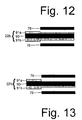
- Fig. 12 is a schematic diagram of rotor member 22b in a partially worn state. Although brake pads 76 wear second and third rotor members 91a and 91b evenly, the remaining portion of second rotor member 91 a is less than the remaining portion of third rotor member 91b, since the original thickness t2 of second rotor member 91 a was less than the original thickness of third rotor member 91b.
- Fig. 13 is a schematic diagram of rotor member 22b after further use. The thinner second rotor member 91a and the even wear produced by brake pads 76 results in second rotor member 91a being completely worn away, while third rotor member 91b still has some thickness remaining.
- braking effectiveness will decrease, but not as drastically as if both second and third rotor members 91a and 91b were completely worn. The rider will notice the decrease in braking effectiveness and can replace the rotor member 22b before braking effectiveness becomes unacceptable.
- the first rotor member 90 was made of aluminum, and the second and third rotor members 91 a and 91 b were made of stainless steel, but other materials could be used.
- second and third rotor members 91a and 91b should have higher wear resistance than first rotor member 90, and first rotor member 90 should be lighter and have better thermal conductivity than second and third rotor members 91 a and 91b in order to ensure lighter weight and better heat dissipation.
- first rotor member 90 could be made of a light carbon fiber-reinforced resin or carbon graphite, and second and third rotor members 91 a and 91b may be made of a ceramic.
- First rotor member 90 also may be made of a titanium or magnesium alloy.
- threaded hexagonal bolts and fixing pins were used to fix rotor member 22b to the other hub components, but other fixing schemes may be used, such as butt deposition, press bonding, or welding.
- first, second and third rotor members 90 and 91 were press welded together and then attached as a unit to hub mounting member 22a, such press welding is not necessary. Instead, the rotor members may be individually mounted to hub mounting member 22a.
Abstract
Description
- The present invention is directed to bicycles and, more particularly, to a bicycle disk brake rotor.
- Conventional bicycle disk brake devices comprise a disk rotor that rotates with the bicycle wheel, and calipers with brake pads that frictionally contact the disk rotor to slow or stop the wheel. The disk rotor may be a metal member that comprises a mounting member and a ring-shaped rotor member fixed to the mounting member, wherein the mounting member is structured to be mounted to the bicycle wheel hub. Since bicycles are propelled by human power, reducing the weight of the bicycle components is an important objective of many bicycle manufacturers. This includes reducing the weight of disk brake devices. On the other hand, it is also desirable to resist rotor wear caused by friction with the brake pads while providing proper heat dissipation.
- One example of a disk rotor with laminated components used in the automotive field is disclosed in Japanese Patent Number (JP) 2,679,162. That disk rotor comprises an annular aluminum first rotor member sandwiched between a pair of annular stainless steel second rotor members. The stainless steel second rotor members provide wear resistance, while the aluminum first rotor member provides heat dissipation.
- Fig. 1 is a schematic diagram of a known
disk rotor 1, not necessarily in the prior art, that resembles the disk rotor disclosed in JP 2,679,162. This rotor comprises afirst rotor member 2 sandwiched between a pair ofsecond rotor members 3, wherein a pair ofbrake pads 4 contact respective outer surfaces of thesecond rotor members 3 during use. The thicknesses t2 of thesecond rotor members 3 typically are the same to simplify manufacturing. As a result, thesecond rotor members 3 typically wear evenly during use as shown in Fig. 2. Eventually, thebrake pads 4 completely wear away thesecond rotor members 3 as shown in Fig. 3. At that time, braking effectiveness decreases significantly. The rider readily notices such reduced braking effectiveness and usually considers it unacceptable. - The present invention is directed to various features of a bicycle disk brake rotor apparatus. In one embodiment, a bicycle disk brake rotor apparatus comprises a first rotor member, a second rotor member, and a third rotor member, wherein the first rotor member is attached to and is disposed between the second rotor member and the third rotor member. A thickness of the second rotor member is different from a thickness of the third rotor member. Additional inventive features will become apparent from the description below, and such features alone or in combination with the above features may form the basis of further inventions as recited in the claims and their equivalents.
-
- Fig. 1 is a schematic diagram of a known disk rotor apparatus;
- Fig. 2 is a schematic diagram of the disk rotor apparatus shown in Fig. 1 with the outer braking layers partially worn;
- Fig. 3 is a schematic diagram of the disk rotor apparatus shown in Fig. 1 with the outer braking layers completely worn;
- Fig. 4 is a side view of a bicycle with a particular embodiment of a disk brake apparatus;
- Fig. 5 is a side view of the disk brake apparatus;
- Fig. 6 is an exploded schematic view of the brake caliper assembly;
- Fig. 7 is a plan view of a particular embodiment of a brake operating device;
- Fig. 8 is a schematic diagram of a particular embodiment of a hydraulic circuit for the disk brake apparatus;
- Fig. 9(A) is a plan view of a first rotor member;
- Fig. 9(B) is a plan view of a second rotor member;
- Fig. 10 is a cross sectional view of a portion of the brake rotor;
- Fig. 11 is a flow chart of a particular embodiment of a process for producing the brake rotor;
- Fig. 12 is a schematic diagram of the disk rotor apparatus shown in Fig. 10 in a partially worn state; and
- Fig. 13 is a schematic diagram of the disk rotor apparatus shown in Fig. 10 showing a second rotor member in a completely worn state.
- Fig. 4 is a side view of a
bicycle 10 with a particular embodiment of a completedisk brake apparatus 12, and Fig. 5 is a side view ofdisk brake apparatus 12.Bicycle 10 is a conventional one with aframe 14 supporting ahandlebar 15, front and rear forks 16 (only the front fork is shown), front and rear wheels 17 (only the front wheel is shown), and a drive device comprising a sprocket and chain (not shown). Since the structure of such a conventional bicycle is well known in the field, further description if its structure shall be omitted. -
Disk brake apparatus 12 comprises abrake caliper 21 mounted onfront fork 16, abrake rotor 22 attached to ahub 17a offront wheel 17 so thatbrake rotor 22 rotates integrally withfront wheel 17, and abrake operating mechanism 23.Brake caliper 21 is attached tofront fork 16 nearbrake rotor 22, and it applies a frictional force tobrake rotor 22 in response to the operation ofbrake operating mechanism 23 to stop the rotation ofbrake rotor 22 andfront wheel 17. - As shown in Figs. 5 and 6,
brake caliper 21 comprises ahousing 50 and apiston unit 51.Housing 50 is constructed of a thermally conducting material such as an aluminum alloy, and it comprises a first housing member 52a and asecond housing member 52b bolted together in a conventional manner to form a slot to receivebrake rotor 22 therebetween.Housing members 52a and 52b have substantially the same shape, except thathydraulic tubing 86 forbrake operating mechanism 23 is connected tosecond housing member 52b to supply brake oil to bothhousing members 52a and 52b.Second housing member 52b also has an outwardly extending flange that forms anattachment member 54 for boltingbrake caliper 21 tofront fork 16. - As shown in Fig. 6,
piston unit 51 comprises fourpistons 74 and a pair ofbrake pads 76. Pistons 74 slidably fit intoround cylinders 57a and 57b formed inhousing members 52a and 52b so as to move between a brake release position and a braking position.Brake pads 76 move integrally withpistons 74. Thus, whenpistons 74 move from the brake release position to the braking position, thebrake pads 76 also move from the brake release position to the braking position. When in the braking position,brake pads 76 press against and apply a frictional force to brakerotor 22 to thereby decrease or stop rotation ofbrake rotor 22 andfront wheel 17. When in the brake release position, thebrake pads 76 are spaced apart frombrake rotor 22, thus allowingbrake rotor 22 andfront wheel 17 to freely rotate. - As shown in Figs 7 and 8, the
brake operating mechanism 23 is attached tohandlebar 15.Brake operating mechanism 23 comprises abrake lever assembly 80, amaster cylinder 81, apiston 82, and anoperating fluid tank 83.Brake lever assembly 80 comprises abracket 84 mounted onhandlebar 15 and alever component 85 pivotably mounted onbracket 84. Bracket 84 is integrally formed withmaster cylinder 81, andpiston 82 andoperating fluid tank 83 are supported bybracket 84. Piston 82 is slidingly disposed withinmaster cylinder 81, andoperating fluid tank 83 is in fluid communication withmaster cylinder 81. One end ofpiston 82 is connected tolever component 85 so thatpiston 82 reciprocates insidemaster cylinder 81 in response to the pulling and releasing oflever component 85.Pulling lever component 85 causes pressurized oil to move through thehydraulic tubing 86 connected tobrake caliper 21, the pressurized oil movespistons 74,brake pads 76 contact and apply frictional force tobrake rotor 22, and thefront wheel 17 is braked. - As shown in Fig. 5,
brake rotor 22 comprises a centrally disposedhub mounting member 22a attached tohub 17a, a ring-shaped rotor member 22b for contactingbrake pads 76, and a plurality offixing pins 22c that fixrotor member 22b tohub mounting member 22a. In this embodiment,hub mounting member 22a is constructed of an aluminum alloy and comprises a centrally disposed cylindricalhub attachment component 40 and arotor attachment component 41.Hub attachment component 40 is attached tohub 17a through a splined component 40a, androtor attachment component 41 extends radially outwardly fromhub attachment component 41. More specifically,rotor attachment component 41 has fivearm components 41a extending radially outwardly fromhub attachment component 40. Afixing hole 41b for fixinghub attachment component 41 torotor member 22b is formed at the tip of eacharm component 41 a. - As shown in Fig. 10,
rotor member 22b may be a laminated structure comprising afirst rotor member 90 sandwiched between asecond rotor member 91a and athird rotor member 91b.First rotor member 90 may be formed from aluminum, which has a relatively high thermal conductivity, whereas second andthird rotor members third rotor members first rotor member 90. - In this embodiment, a thickness t1 of
first rotor member 90 is from approximately 0.5 mm to approximately 1.5 mm, and thicknesses t2 and t3 ofsecond member 91 a andthird rotor member 91b, respectively, are from approximately 0.2 mm to approximately 0.8 mm. Setting the thicknesses ofrotor members first rotor member 90 that has lighter weight while preserving strength, and the relatively thinner second andthird rotor members third rotor members second rotor member 91 a is less than thickness t3 ofthird rotor member 91b. - Fig. 9(A) is a plan view of
first rotor member 90, and Fig. 9(B) is a plan view ofsecond rotor member 91 a.Third rotor member 91b has the same structure assecond rotor member 91 a, so a separate description ofthird rotor member 91b shall be omitted. Furthermore,first rotor member 90 and second andthird rotor members first rotor member 90 comprises a ring-shapedmember 90a with a plurality of circumferentially distributedholes 90c for ventilation and weight reduction.First rotor member 90 also includes a plurality of circumferentially distributed and radially inwardly extending fixingcomponents 90b, wherein each fixingcomponent 90b has acorresponding fixing hole 90d. As shown in Fig. 9(B),second rotor member 91 a comprises a ring-shaped member 9 1 c with a plurality of circumferentially distributedholes 91d and a plurality of circumferentially distributed and radially inwardly extendingsecond fixing components 91 e, wherein eachsecond fixing component 91e has acorresponding fixing hole 91f. As shown in Fig. 10, each fixinghole 90d infirst rotor member 90 is aligned with a corresponding one of the fixingholes 91f insecond rotor member 91 a and a corresponding fixinghole 91 g inthird rotor member 91b for receiving a fixingpin 22c therethrough. Each fixingpin 22c may be formed from aluminum and, as noted above, fixingpins 22c are used to fixrotor member 22b tohub mounting member 22a. - Fig. 11 is a flow chart of a particular embodiment of a process for producing
rotor member 22b. In general,rotor member 22b may be produced by laminating an aluminum sheet between a pair of stainless steel sheets and then stamping the laminated structure. More specifically, an aluminum sheet that will formfirst rotor member 90 and the stainless steel sheets that will form the second andthird rotor members rotor member 22b having the desired shape. Any warping in the resulting rotor material is then corrected to finish therotor member 22b in a Step S4. - The foregoing process allows a
first rotor member 90 to be joined with second andthird rotor members overall rotor member 22b in a simple manner, wherein the individual rotor members may be formed of different materials. The resultingrotor member 22b then may be fixed tohub mounting member 22a, thus simplifying the manufacturing process. Also, the method of fixingrotor member 22b tohub mounting member 22a prevents rotor members 91 from separating fromrotor member 90. - Fig. 12 is a schematic diagram of
rotor member 22b in a partially worn state. Althoughbrake pads 76 wear second andthird rotor members second rotor member 91 a is less than the remaining portion ofthird rotor member 91b, since the original thickness t2 ofsecond rotor member 91 a was less than the original thickness ofthird rotor member 91b. Fig. 13 is a schematic diagram ofrotor member 22b after further use. The thinnersecond rotor member 91a and the even wear produced bybrake pads 76 results insecond rotor member 91a being completely worn away, whilethird rotor member 91b still has some thickness remaining. In this case, braking effectiveness will decrease, but not as drastically as if both second andthird rotor members rotor member 22b before braking effectiveness becomes unacceptable. - While the above is a description of various embodiments of inventive features, further modifications may be employed without departing from the spirit and scope of the present invention. For example, in the above embodiment, the
first rotor member 90 was made of aluminum, and the second andthird rotor members third rotor members first rotor member 90, andfirst rotor member 90 should be lighter and have better thermal conductivity than second andthird rotor members first rotor member 90 could be made of a light carbon fiber-reinforced resin or carbon graphite, and second andthird rotor members First rotor member 90 also may be made of a titanium or magnesium alloy. - In the described embodiments, threaded hexagonal bolts and fixing pins were used to fix
rotor member 22b to the other hub components, but other fixing schemes may be used, such as butt deposition, press bonding, or welding. - While the first, second and
third rotor members 90 and 91 were press welded together and then attached as a unit tohub mounting member 22a, such press welding is not necessary. Instead, the rotor members may be individually mounted tohub mounting member 22a. - The size, shape, location or orientation of the various components may be changed as desired. Components that are shown directly connected or contacting each other may have intermediate structures disposed between them. The functions of one element may be performed by two, and vice versa. The structures and functions of one embodiment may be adopted in another embodiment. It is not necessary for all advantages to be present in a particular embodiment at the same time. Every feature which is unique from the prior art, alone or in combination with other features, also should be considered a separate description of further inventions by the applicant, including the structural and/or functional concepts embodied by such feature(s). Thus, the scope of the invention should not be limited by the specific structures disclosed or the apparent initial focus or emphasis on a particular structure or feature.
Claims (9)
- A bicycle disk brake rotor apparatus (22) comprising:a first rotor member (90);a second rotor member (91a);a third rotor member (91b);wherein the first rotor member (90) is attached to and is disposed between the second rotor member (91 a) and the third rotor member (91b); andwherein a thickness of the second rotor member (91a) is different from a thickness of the third rotor member (91b).
- The apparatus (22) according to claim 1 wherein the first rotor member (90) has greater thermal conductivity than the second rotor member (91 a) and the third rotor member (91b).
- The apparatus (22) according to claim 1 or 2 wherein the first rotor member (90) comprises aluminum, and wherein the second rotor member (91a) and the third rotor member (91b) each comprises stainless steel.
- The apparatus (22) according to any of the preceding claims wherein each of the second rotor member (91a) and the third rotor member (91b) is formed with a hardening process.
- The apparatus (22) according to any of the preceding claims wherein the second rotor member (91a) and the third rotor member (91b) are pressure welded to the first rotor member (90).
- The apparatus (22) according to any of claims 1 to 4 wherein the second rotor member (91a) and the third rotor member (91b) are hot rolled to the first rotor member (90).
- The apparatus (22) according to any of claims 1 to 4 wherein the second rotor member (91a) and the third rotor member (91b) are forge welded to the first rotor member (90).
- The apparatus (22) according to any of the preceding claims wherein the first rotor member (90) has a thickness of from approximately 0.5 millimeters to approximately 1.5 millimeters, and wherein the second rotor member (91 a) and the third rotor member (91b) each has a thickness of from approximately 0.2 millimeters to approximately 0.8 millimeters.
- The apparatus (22) according to any of the preceding claims wherein each of the second rotor member (91a) and the third rotor member (91b) is formed of a material having greater braking wear resistance than the first rotor member (90).
Applications Claiming Priority (1)
| Application Number | Priority Date | Filing Date | Title |
|---|---|---|---|
| US10/923,452 US20060037819A1 (en) | 2004-08-19 | 2004-08-19 | Bicycle disk brake rotor with laminated components having differing thicknesses |
Publications (2)
| Publication Number | Publication Date |
|---|---|
| EP1627809A2 true EP1627809A2 (en) | 2006-02-22 |
| EP1627809A3 EP1627809A3 (en) | 2007-10-24 |
Family
ID=35149603
Family Applications (1)
| Application Number | Title | Priority Date | Filing Date |
|---|---|---|---|
| EP05015696A Withdrawn EP1627809A3 (en) | 2004-08-19 | 2005-07-19 | Bicycle disk brake rotor with laminated components having differing thicknesses |
Country Status (6)
| Country | Link |
|---|---|
| US (1) | US20060037819A1 (en) |
| EP (1) | EP1627809A3 (en) |
| JP (1) | JP2006057843A (en) |
| CN (1) | CN1736795A (en) |
| BR (1) | BRPI0502823A (en) |
| TW (1) | TWI248898B (en) |
Cited By (1)
| Publication number | Priority date | Publication date | Assignee | Title |
|---|---|---|---|---|
| AT516124A1 (en) * | 2014-07-17 | 2016-02-15 | Miba Frictec Gmbh | friction plate |
Families Citing this family (15)
| Publication number | Priority date | Publication date | Assignee | Title |
|---|---|---|---|---|
| US20090084639A1 (en) * | 2007-10-01 | 2009-04-02 | James Colegrove | Bicycle brake system |
| US8522931B2 (en) * | 2010-03-30 | 2013-09-03 | Shimano Inc. | Disk brake rotor |
| US11274717B2 (en) | 2010-07-02 | 2022-03-15 | Shimano Inc. | Brake rotor assembly |
| US9777784B2 (en) | 2011-03-02 | 2017-10-03 | Shimano, Inc. | Disk brake rotor with hollow portions |
| US8978842B2 (en) | 2011-11-24 | 2015-03-17 | Shimano Inc. | Bicycle disc brake rotor |
| US9725131B2 (en) * | 2011-11-24 | 2017-08-08 | Shimano Inc. | Bicycle disc brake rotor |
| US8813921B2 (en) | 2011-11-24 | 2014-08-26 | Shimano Inc. | Bicycle disc brake rotor |
| US8881873B2 (en) * | 2012-01-18 | 2014-11-11 | Shimano Inc. | Bicycle disc brake rotor |
| US9561835B2 (en) | 2012-06-19 | 2017-02-07 | Shimano Inc. | Bicycle brake assembly |
| US9593727B1 (en) * | 2015-10-06 | 2017-03-14 | Shimano Inc. | Bicycle disc brake rotor |
| US10428886B2 (en) | 2016-03-29 | 2019-10-01 | Shimano Inc. | Bicycle disc brake rotor |
| US10480601B2 (en) | 2016-06-22 | 2019-11-19 | Sram, Llc | Heat dissipating brake rotor |
| DE102017117256A1 (en) * | 2017-07-31 | 2019-01-31 | Shimano Inc. | brake disc rotor |
| TWI625266B (en) * | 2017-08-04 | 2018-06-01 | Tien Hsin Industries Co Ltd | Bicycle brake disc |
| TWI644740B (en) * | 2017-12-19 | 2018-12-21 | 至興精機股份有限公司 | Method for manufacturing a floating disk including a forged workpiece |
Citations (1)
| Publication number | Priority date | Publication date | Assignee | Title |
|---|---|---|---|---|
| JP2679162B2 (en) | 1988-10-22 | 1997-11-19 | スズキ株式会社 | Disc brake rotor structure |
Family Cites Families (17)
| Publication number | Priority date | Publication date | Assignee | Title |
|---|---|---|---|---|
| US3712427A (en) * | 1970-11-05 | 1973-01-23 | Goodyear Tire & Rubber | Graphite and/or carbon disk with removable wear faces |
| JPS6141026A (en) * | 1984-08-03 | 1986-02-27 | Dia Hitoko Konpojitsuto Kk | Brake disc |
| JPS6277336U (en) * | 1985-11-01 | 1987-05-18 | ||
| US4848553A (en) * | 1988-03-29 | 1989-07-18 | Dana Corporation | Friction laminate and disk assembly |
| JPH0526268A (en) * | 1991-07-19 | 1993-02-02 | Izumi Ind Ltd | Brake disc and manufacture thereof |
| JPH05146880A (en) * | 1991-11-28 | 1993-06-15 | Nippon Stainless Steel Co Ltd | Manufacture of al/stainless steel clad coil material |
| US5501306A (en) * | 1994-06-10 | 1996-03-26 | Martino; Gerald | Brake rotor with a heat-resistant ceramic coating |
| JP3168836B2 (en) * | 1994-07-26 | 2001-05-21 | 住友金属工業株式会社 | Manufacturing method of stainless steel and aluminum clad material |
| SE508721C2 (en) * | 1995-05-08 | 1998-11-02 | Volvo Wheel Loaders Ab | Brake slats with built-in acoustic wear warning |
| US5901818A (en) * | 1995-05-16 | 1999-05-11 | Martino; Gerald | Brake rotors with heat-resistant ceramic coatings |
| JPH11287268A (en) * | 1998-04-03 | 1999-10-19 | Kiriu Mach Mfg Co Ltd | Ventilated type brake disc rotor |
| US6079611A (en) * | 1998-12-28 | 2000-06-27 | Shimano Inc. | Method of manufacturing ventilated brake disc |
| JP4627346B2 (en) * | 2000-03-31 | 2011-02-09 | 本田技研工業株式会社 | brake disc |
| JP3654854B2 (en) * | 2001-07-16 | 2005-06-02 | 株式会社シマノ | Bicycle disc brake device and method of manufacturing the disc rotor |
| DE60210172T2 (en) * | 2002-08-01 | 2006-12-28 | Borgwarner Inc., Auburn Hills | Washer for power transmission unit |
| JP2004138154A (en) * | 2002-10-17 | 2004-05-13 | Mazda Motor Corp | Brake disk made of light alloy |
| JP2005030565A (en) * | 2003-07-11 | 2005-02-03 | Shimano Inc | Disk rotor for bicycle |
-
2004
- 2004-08-19 US US10/923,452 patent/US20060037819A1/en not_active Abandoned
-
2005
- 2005-03-23 TW TW094108986A patent/TWI248898B/en not_active IP Right Cessation
- 2005-04-30 CN CNA2005100667800A patent/CN1736795A/en active Pending
- 2005-07-12 BR BRPI0502823-0A patent/BRPI0502823A/en not_active IP Right Cessation
- 2005-07-19 EP EP05015696A patent/EP1627809A3/en not_active Withdrawn
- 2005-08-08 JP JP2005229684A patent/JP2006057843A/en not_active Ceased
Patent Citations (1)
| Publication number | Priority date | Publication date | Assignee | Title |
|---|---|---|---|---|
| JP2679162B2 (en) | 1988-10-22 | 1997-11-19 | スズキ株式会社 | Disc brake rotor structure |
Cited By (1)
| Publication number | Priority date | Publication date | Assignee | Title |
|---|---|---|---|---|
| AT516124A1 (en) * | 2014-07-17 | 2016-02-15 | Miba Frictec Gmbh | friction plate |
Also Published As
| Publication number | Publication date |
|---|---|
| TW200607699A (en) | 2006-03-01 |
| JP2006057843A (en) | 2006-03-02 |
| EP1627809A3 (en) | 2007-10-24 |
| US20060037819A1 (en) | 2006-02-23 |
| BRPI0502823A (en) | 2006-04-04 |
| TWI248898B (en) | 2006-02-11 |
| CN1736795A (en) | 2006-02-22 |
Similar Documents
| Publication | Publication Date | Title |
|---|---|---|
| EP1627809A2 (en) | Bicycle disk brake rotor with laminated components having differing thicknesses | |
| EP1496282B1 (en) | Bicycle disk brake apparatus with laminated components | |
| EP1619405B1 (en) | Bicycle disc brake rotor | |
| US9551389B2 (en) | Bicycle disc brake caliper | |
| US8342299B2 (en) | Bicycle disk brake pad with welded and adhesively bonded layers | |
| US8550220B2 (en) | Bicycle brake pad | |
| EP1878935B1 (en) | Bicycle disk brake caliper with a recursive cooling system | |
| JP2007092929A (en) | Disc brake pad for bicycle | |
| US9725131B2 (en) | Bicycle disc brake rotor | |
| US8881873B2 (en) | Bicycle disc brake rotor | |
| US7997389B2 (en) | Bicycle with front and rear disk brakes operable approximately simultaneously | |
| US7784593B2 (en) | Bicycle disk brake pad with a titanium backing plate | |
| EP1304496B1 (en) | Disk brake for vehicle with bar handle | |
| US20130133994A1 (en) | Bicycle disc brake rotor | |
| JP2003254360A (en) | Disc brake of floating type | |
| JP2012197021A (en) | Vehicle brake device | |
| JP2011075036A (en) | Disk brake |
Legal Events
| Date | Code | Title | Description |
|---|---|---|---|
| PUAI | Public reference made under article 153(3) epc to a published international application that has entered the european phase |
Free format text: ORIGINAL CODE: 0009012 |
|
| AK | Designated contracting states |
Kind code of ref document: A2 Designated state(s): AT BE BG CH CY CZ DE DK EE ES FI FR GB GR HU IE IS IT LI LT LU LV MC NL PL PT RO SE SI SK TR |
|
| AX | Request for extension of the european patent |
Extension state: AL BA HR MK YU |
|
| RAP1 | Party data changed (applicant data changed or rights of an application transferred) |
Owner name: SHIMANO INC. |
|
| PUAL | Search report despatched |
Free format text: ORIGINAL CODE: 0009013 |
|
| AK | Designated contracting states |
Kind code of ref document: A3 Designated state(s): AT BE BG CH CY CZ DE DK EE ES FI FR GB GR HU IE IS IT LI LT LU LV MC NL PL PT RO SE SI SK TR |
|
| AX | Request for extension of the european patent |
Extension state: AL BA HR MK YU |
|
| 17P | Request for examination filed |
Effective date: 20080222 |
|
| 17Q | First examination report despatched |
Effective date: 20080320 |
|
| AKX | Designation fees paid |
Designated state(s): DE IT NL |
|
| STAA | Information on the status of an ep patent application or granted ep patent |
Free format text: STATUS: THE APPLICATION HAS BEEN WITHDRAWN |
|
| 18W | Application withdrawn |
Effective date: 20080704 |