EP1626566A1 - Image processing for expressing gradation - Google Patents
Image processing for expressing gradation Download PDFInfo
- Publication number
- EP1626566A1 EP1626566A1 EP04731768A EP04731768A EP1626566A1 EP 1626566 A1 EP1626566 A1 EP 1626566A1 EP 04731768 A EP04731768 A EP 04731768A EP 04731768 A EP04731768 A EP 04731768A EP 1626566 A1 EP1626566 A1 EP 1626566A1
- Authority
- EP
- European Patent Office
- Prior art keywords
- tone
- values
- corrected values
- bits
- corrected
- Prior art date
- Legal status (The legal status is an assumption and is not a legal conclusion. Google has not performed a legal analysis and makes no representation as to the accuracy of the status listed.)
- Withdrawn
Links
- 238000000034 method Methods 0.000 claims abstract description 73
- 238000006243 chemical reaction Methods 0.000 claims abstract description 23
- 238000003702 image correction Methods 0.000 claims description 45
- 238000003672 processing method Methods 0.000 claims description 19
- 230000006870 function Effects 0.000 claims description 17
- 238000004590 computer program Methods 0.000 claims description 10
- 238000009792 diffusion process Methods 0.000 claims description 5
- 238000005516 engineering process Methods 0.000 abstract description 7
- 239000011159 matrix material Substances 0.000 description 19
- 238000010276 construction Methods 0.000 description 6
- 238000010586 diagram Methods 0.000 description 5
- 230000008030 elimination Effects 0.000 description 3
- 238000003379 elimination reaction Methods 0.000 description 3
- 230000015572 biosynthetic process Effects 0.000 description 2
- 239000003086 colorant Substances 0.000 description 2
- 238000011946 reduction process Methods 0.000 description 2
- 238000005070 sampling Methods 0.000 description 2
- 238000012935 Averaging Methods 0.000 description 1
- 101100443238 Caenorhabditis elegans dif-1 gene Proteins 0.000 description 1
- 101100277917 Caenorhabditis elegans dmd-3 gene Proteins 0.000 description 1
- 101100277918 Caenorhabditis elegans dmd-4 gene Proteins 0.000 description 1
- QAHFOPIILNICLA-UHFFFAOYSA-N Diphenamid Chemical compound C=1C=CC=CC=1C(C(=O)N(C)C)C1=CC=CC=C1 QAHFOPIILNICLA-UHFFFAOYSA-N 0.000 description 1
- 238000004458 analytical method Methods 0.000 description 1
- 230000006866 deterioration Effects 0.000 description 1
- 230000001747 exhibiting effect Effects 0.000 description 1
- 235000012736 patent blue V Nutrition 0.000 description 1
- 238000003786 synthesis reaction Methods 0.000 description 1
Images


Classifications
-
- H—ELECTRICITY
- H04—ELECTRIC COMMUNICATION TECHNIQUE
- H04N—PICTORIAL COMMUNICATION, e.g. TELEVISION
- H04N1/00—Scanning, transmission or reproduction of documents or the like, e.g. facsimile transmission; Details thereof
- H04N1/40—Picture signal circuits
- H04N1/407—Control or modification of tonal gradation or of extreme levels, e.g. background level
-
- G—PHYSICS
- G06—COMPUTING; CALCULATING OR COUNTING
- G06T—IMAGE DATA PROCESSING OR GENERATION, IN GENERAL
- G06T5/00—Image enhancement or restoration
- G06T5/90—Dynamic range modification of images or parts thereof
- G06T5/92—Dynamic range modification of images or parts thereof based on global image properties
-
- H—ELECTRICITY
- H04—ELECTRIC COMMUNICATION TECHNIQUE
- H04N—PICTORIAL COMMUNICATION, e.g. TELEVISION
- H04N1/00—Scanning, transmission or reproduction of documents or the like, e.g. facsimile transmission; Details thereof
- H04N1/40—Picture signal circuits
- H04N1/409—Edge or detail enhancement; Noise or error suppression
Definitions
- the present invention relates to a digital image processing technology for carrying out tone expression.
- the number of bits included in the conventional corrected value is identical to the number of bits included in the input image value.
- Figs. 10A through 10D show the process for determining the conventional corrected value in the technology of the prior art.
- Fig. 10A is a tone curve showing the relationship between an input pixel value DI and a conventional corrected value J, and shows an example in which both the input pixel value DI and the conventional corrected value J have eight bits.
- the conventional corrected value Jb becomes a discrete value 128.
- Fig. 10A is a tone curve showing the relationship between an input pixel value DI and a conventional corrected value J, and shows an example in which both the input pixel value DI and the conventional corrected value J have eight bits.
- Fig. 10B shows an example in which the value 127 of the input pixel value DI for
- FIG. 10C shows a case in which, where the input pixel value DIc is 128 and the original-bit continuous value Ac is 128.7, the conventional corrected value Jc also becomes 128.
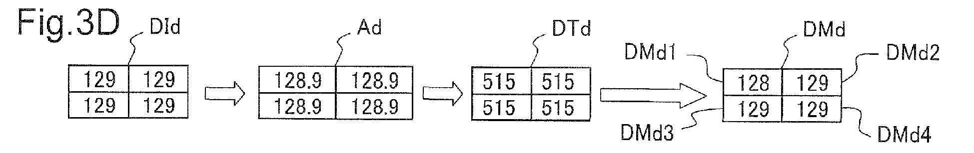
- Fig. 10D shows a case in which, where the input pixel value DId is 129 and the original-bit continuous value Ad is 128.9, the conventional corrected value Jd becomes 128.
- the prior art technology described above entails the problem that even where the input pixel values DI are different, the corresponding corrected values J are identical, and the tones associated with the input pixel values are lost.
- the present invention was devised in order to resolve these problems, and an object thereof is to provide an image processing technology that offers superior tone expression and does not cause deterioration in tone reproducibility even where correction is performed using a tone curve.
- an image processing method for correcting pixel values of input pixels comprising the steps of: (i) establishing a conversion relationship that indicates relationship between the input pixel values and first tone-corrected values which are corrected from the input pixel values; (ii) converting the input pixel values according to the conversion relationship into the first tone-corrected values having a higher number of bits than the input pixel values; and (iii) generating from the first tone-corrected values second tone-corrected values having a smaller number of bits than the first tone-corrected values, wherein the step (iii) generates the second tone-corrected values such that a tone of the first tone-corrected values is expressed by a plurality of the second tone-corrected values for a plurality of mutually adjacent pixels.
- the input pixel values are converted into first tone-corrected values having a higher number of tones, and a tone of the first tone-corrected values is expressed by the second tone-corrected values for multiple pixels, an image with superior tone expression can be obtained.
- the number of bits of the second tone-corrected values is smaller than the number of bits of the first tone-corrected values, post-tone correction processes can be carried out without a significant increase in the processing burden.
- the second tone-corrected values may have the same number of bits as the input pixel values.
- the processing burden after the tone processing does not change. Nevertheless, because the input pixel values are converted into the first tone-corrected values having a higher number of tones, and a tone of the first tone-corrected values is expressed using the second tone-corrected values for multiple pixels, an image with superior tone expression can be achieved.
- tone expression can be increased dramatically.
- the step (iii) may be a step in which the number of bits of the first tone-corrected values is reduced using a dithering method.
- the number of elements in the dithering matrix used in the step (iii) equals the number that is obtained by dividing the number of tones that can be expressed by the number of bits of the first tone-corrected values by the number of tones that can be expressed by the number of bits of the second tone-corrected values. According to this image processing method, an image exhibiting superior tone expression can be obtained via processing using a small-sized matrix.
- the step (iii) may be a step that reduces the number of bits of the first tone-corrected values using an error diffusion method.
- the above image processing method may further comprise the steps of: executing, between the steps (ii) and (iii), a first image correction process to the first tone-corrected values to correct the first tone-corrected values; and executing, after the step (iii), a second image correction process using the second tone-corrected values.
- the first image correction process is a process executed while a relatively small amount of image data is stored in a buffer memory
- the second image correction process is a process executed while a relatively large amount of image data is stored in the buffer memory
- the first image correction process include saturation correction and that the second image correction process include sharpness adjustment.
- the present invention may be realized in various forms, and may be realized in the form of an image processing apparatus or computer program that implements an image processing method, a recording medium on which such computer program is recorded, or the like.
- Fig. 1 is a block diagram showing the construction of an image processing apparatus comprising an embodiment of the present invention.
- This image processing system includes a computer 90 and a printer 20.
- the image processing system that includes the printer 20 and the computer 90 can be generally termed an 'image processing apparatus'.
- an application program 95 is executed under the control of a prescribed operating system.
- the operating system incorporates a video driver 91 and printer driver 96, and print data PD to be relayed to the printer 20 is output from the application program 95 via these drivers.
- the application program 95 that performs image editing and the like performs desired processing to the image to be processed, and displays the image on a CRT 21 via the video driver 91.
- the printer driver 96 of the computer 90 receives the image data from the application program 95 and converts it into print data PD to be supplied to the printer 20.
- the printer driver 96 incorporates a tone conversion module 97, a color conversion module 98, a halftone module 99, a rasterizer 100 and a color conversion lookup table LUT.
- the tone conversion module 97 comprises a tone correction module 97a and a bit number reduction module 97b.
- the image data received from the application program 95 comprises multiple input pixel values DI, and each input pixel value DI is converted by the tone correction module 97a into a first tone-corrected value DT having a larger number of bits than the input pixel value DI.
- the first tone-corrected value DT is converted by the bit number reduction module 97b into a second tone-corrected value DM having a smaller number of bits than the first tone-corrected value DT.
- the second tone-corrected value DM is image information composed of the three RGB color components.
- the color conversion module 98 uses the color conversion lookup table LUT to convert the RGB image data on a pixel-by pixel basis into multiple-tone data for the multiple ink colors that can be used by the printer 20.
- the converted multiple-tone data has 256 tones, for example.
- the halftone module 99 generates halftone data by carrying out so-called halftone processing.
- This halftone image data is arranged in the order in which the data is to be relayed to the printer 20 by the rasterizer 100 and is then output as final print data PD.
- the print data PD includes raster data indicating the dot formation states for each main scan pass and data indicating sub-scan feed amounts.
- the printer driver 96 is equivalent to a program that implements the function to generate the print data PD by executing various types of image processing.
- the program to realize the functions of the printer driver 96 is supplied in the form of a program recorded on a computer-readable recording medium.
- This recording medium may consist of a flexible disk, CD-ROM, magnetic disk, IC card, ROM cartridge, punch card, printed matter on which a bar code or other symbols are printed, or any of other various types of computer-readable media, such as a recording device disposed inside the computer (such as RAM, ROM or other memory) or outside the computer.
- Fig. 2 shows the tone conversion module 97 in a first embodiment.
- the tone correction module 97a performs tone curve correction to an eight-bit input pixel value DI to generate a 10-bit first tone-corrected value DT.
- the bit number reduction module 97b carries out the bit reduction processing described below to the 10-bit first tone-corrected value DT to generate an eight-bit second tone-corrected value DM.
- Figs. 3A through 3E show the relationship between the input pixel value DI and the second tone-corrected value DM.
- Fig. 3A is a tone curve showing the relationship between the eight-bit input pixel value DI and the 10-bit first tone-corrected value DT.
- the maximum value of 255 for the input pixel value DI is set so as to correspond to the maximum value of 1020 of the first tone-corrected value DT.
- the reason that the maximum value of the first tone-corrected value DT is smaller than the maximum value expressible by 10 bits (i.e., 1023) is described below.
- the process for determining the first tone-corrected value DT in the first embodiment is described below using an example in which the input pixel value Dib is 127 and the original bit continuous value Ab is 128.2.
- the first tone-corrected value DTb is a value derived by multiplying the original bit continuous value Ab by four and rounding off.
- the procedure for determining the second tone-corrected value DM will now be described.
- the dithering matrix P is a matrix in which the values of 0 to 3 are allocated to the four pixels P1 through P4 arranged in a 2 x 2 fashion.
- INT[X] is a function that obtains an integer value by eliminating the decimal portion of a value X
- Pi is the value of the ith element of the dithering matrix P where i is an integer from 1 to 4.
- the second tone-corrected values DMb1, DMb2, DMb3 and DMb4 are all values of 128.
- the maximum value of the first tone-corrected value DT obtained via the tone curve is set to 1020 so that the maximum value of the first tone corrected value DT will make the second tone-corrected value DM, according to the equation (1), to be the maximum value of 255 that can be expressed by eight bits.
- the first tone-corrected value DTc becomes 514 via the same processing described above.
- the second tone-corrected values DMc1 and DMc4 at two pixel positions become 128, while the second tone-corrected values DMc2 and DMc2 at the other two pixel positions become 129.
- the first tone-corrected value DTd becomes 516.
- the second tone-corrected value DMd1 at one pixel position becomes 128, while the second tone-corrected values DMd2, DMd3 and DMd4 at the other three pixel positions become 129.
- the input pixel values DI for four adjacent pixels are identical.
- the input pixel values DI may be different from each other.
- Fig. 4 shows an example in which the input pixel values DIf1, DIf2, DIf3 and DIf4 of adjacent input pixels are 127, 128, 128 and 129, respectively.
- the first tone-corrected values DT corresponding to the input pixel values of 127, 128 and 129 are 512, 514 and 515. Therefore, the first tone-corrected values DTf1, DTIf2, DTf3 and DTf4 become 512, 514, 514 and 515, respectively.
- the second tone-corrected values DMf1, DMf2, DMf3 and DMf4 become 128, 129, 129 and 129, respectively.
- a tone of the first tone-corrected values DT obtained by correcting the input pixel value DI based on the tone curve is expressed by a plurality of pixels having the second tone-corrected values DM without increasing the number of bits of the second tone-corrected values DM beyond the number of bits of the input pixel values DI.
- Not increasing the number of bits of the second tone-corrected values DM means not increasing the number of bits of data per color handled by the color conversion module 98 explained with reference to Fig. 1. Therefore, the memory and the processing speed need not be increased dramatically.
- Fig. 5A shows the tone correction module 97 in a second embodiment.
- the input pixel value DI has eight bits
- the first tone-corrected value DT has (8+M) bits
- the second tone-corrected value DM has (8+M-N) bits.
- M is an integer larger than one
- N is any positive integer.
- Fig. 5B shows a tone curve.
- the tone curve is determined such that first tone-corrected values DT ranging from 0 to (2 (8+M) - 2 N ) correspond to input pixel values DI ranging from 0 to (2 8 - 1).
- the maximum value for the first tone-corrected value DT is limited to (2 (8+M) - 2 N ) because the values in the range from (2 (8+M) - 2 (N+1) ) to (2 (8+M) - 1) will make the second tone-corrected value DM to exceed the range of values that can be expressed by the number (8 + M - N) of bits of the second tone-corrected value DM during the bit reduction process carried out by the bit number reduction module 97b.
- the first tone-corrected values DT corresponding to input pixel values DI are obtained in accordance with this tone curve.
- Fig. 5C shows a dithering matrix P applied in the bit reduction module 97b.
- the dithering matrix P has 2 N elements, and the values of the elements of the dithering matrix P range from 0 to (2 N - 1).
- INT[X] is a function that obtains an integer value by eliminating the decimal portion of a value X
- Pi is the value of the ith element of the dithering matrix P where i is an integer from 1 to 2 N .
- the number of tones that can be reproduced by the second tone-corrected values DM can be increased by a power of two.
- the number of tones that can be reproduced by the second tone-corrected values DT increases dramatically as the difference M between the number of bits of the first tone-corrected values DT and the number of bits of the input pixel values DI becomes larger than the difference N between the number of bits of the first tone-corrected values DT and the number of bits of the second tone-corrected values DM.
- Fig. 6 shows the relationship between input pixel values DI and second tone-corrected values DM in a third embodiment.
- This embodiment is an example in which the error diffusion method is applied in determining the second tone-corrected value DM from the first tone-corrected value DT.
- the process until the first tone-corrected value DT is obtained from the input pixel value DI is identical to the corresponding processes described above in connection with the first and second embodiments.
- An example will now be described in which the tone curve is identical to that applied in the first embodiment and the number of bits of the second tone-corrected value DM is two bits smaller than the number of bits of the first tone-corrected value DT.
- the tone curve here is identical to that of the first embodiment, where the input pixel values DIh of four adjacent input pixels are all 128, the first tone-corrected values DTh1 through DTh4 are 514, as shown in Fig. 6.
- MOD[X, Y] is a function to obtain the remainder of division of a value X by Y
- N is the difference between the number of bits of the first tone-corrected value DT and the number of bits of the second tone-corrected value DM.
- the first error-inclusive value DGh1 is 514, which is equal to the first tone-corrected value DTh1.
- the second error-inclusive value DGh2 is 516, which is a sum of the second first tone-corrected value DTh2 and two, which is the remainder of division of the error-inclusive value DGh1 by four.
- the third error-inclusive value DGh3 is 514, which is a sum of the third first tone-corrected value DTh3 of 514 and zero, which is the remainder of division of the second error-inclusive value DGh2 of 516 by four.
- the fourth error-inclusive value DGh3 is 516.
- the second tone-corrected value DM is obtained by dividing the error-inclusive value DG sought in this fashion by four and rounding off fractions of the result of the division.
- the second tone-corrected values DMh1, DMh2, DMh3 and DMh4 respectively become 128, 129, 128 and 129.
- the errors caused by bit reduction can be made inconspicuous and subtle tones can be reproduced.
- Fig. 7 is a block diagram showing the construction of a printer driver of a fourth embodiment. It differs from the printer driver 96 shown in Fig. 1 only in that the tone conversion module 97 is replaced by an image correction module 200, and is otherwise identical to the printer driver 96 shown in Fig. 1.
- the image correction module 200 includes a correction parameter generation module 202 and an enhancement processing module 204.
- the enhancement processing module 204 has a function to perform various image correction processes (described below), as well as functions to serve as the tone correction module 97a and the bit reduction module 97b.
- 'enhancement processing' is processing to increase image quality, and includes various image correction processes such as tone correction, color correction, saturation adjustment and the like.
- the correction parameter generation module 202 creates various correction parameters used during enhancement processing.
- Fig. 8 is a flow chart showing the sequence of operations performed by the image correction module 200.
- the correction parameter generation module 202 determines whether or not a print specification tag is registered in the image data file to be processed.
- a 'print specification tag' has a data structure for storing various parameter values used to carry out various image correction processes (such as tone correction, color correction and saturation adjustment) when an image is printed.
- the print specification tag can be registered in an EXIF file, for example.
- An EXIF file is an image data file format established by the Japan Electronics and Information Technology Association (JEITA).
- step S12 the correction parameter generation module 202 determines whether or not an automatic image correction instruction is present in the print specification tag.
- 'automatic image correction' refers to a process in which correction parameter values are calculated via image sampling and analysis, and image correction is carried out using these correction parameter values.
- An instruction to carry out automatic image correction may also be given via user input in the user interface window of the printer driver.
- step S 19 the image correction module 200 proceeds to step S 19, and the enhancement processing in step S20 is carried out using the correction parameter values included in the print specification tag.
- the image correction module 200 executes the processes of steps S14-S18.
- the correction parameter generation module 202 first samples the image in step S14 and determines various parameter values to be used during enhancement processing in accordance with the results of the sampling. Enhancement processing includes, for example, noise elimination, tone correction, memory color correction, saturation correction, HSB space color correction, sharpness adjustment and the like.
- step S18 the correction parameter values included in the print specification tag and the correction parameter values created in step S 16 are synthesized. This synthesis varies depending on the type of enhancement process, and involves execution of prescribed mathematical operations such as addition or averaging.
- the enhancement processing module 204 performs various types of enhancement processing using the various correction parameter values prepared as described above.
- Fig. 9 is a flow chart showing the enhancement process in detail.
- noise elimination is a process to harmonize very small characteristic pixel values included in an image with surrounding pixel values. This process is executed while several lines' worth of image data is stored in the buffer memory (a temporary work memory).
- the image data to be processed is 8-bits/color/ pixel RGB data.
- tone correction is carried out. This tone correction is identical to the tone correction described in connection with the first through third embodiments. In this process, the number of bits of the RGB data is increased from eight bits to 10 bits, for example.
- step S26 memory color processing is carried out for each of multiple prescribed specific color ranges (skin color, sky blue, green, red). This enables colors in prescribed color ranges to be corrected to the preferred color.
- step S28 saturation correction is carried out. This saturation correction is a process in which saturation is increased via RGB value correction intended to increase the difference between the maximum and minimum RGB values (corresponding to saturation) for each pixel, for example.
- step S30 color correction is carried out using the HSB (Hue, Saturation, Brightness) space.
- the HSB space is also called the HSI (Hue, Saturation, Intensity) space, and is a color space that expresses a given color in terms of the three attributes of hue, saturation and brightness. Because the three attributes (hue, saturation, brightness) can be corrected directly in the HSB space, it enables desired color correction to be performed more accurately than when the RGB space is used. However, because color space conversion must be carried out during processing, the time required for processing increases.
- steps S24 through S30 is carried out while the image data for one line (or one pixel) is stored in the buffer memory.
- the image data to be processed is 10-bits/color/pixel data or 10-bits/attribute/pixel data. Because these processes are carried out to 10-bit data, processing can be performed more accurately than when 8-bit data is processed.
- step S32 bit number reduction processing is performed.
- This bit number reduction processing is identical to that performed in connection with the first through third embodiments described above.
- the number of bits of RGB data is reduced from 10 bits to 8 bits, for example.
- step S34 sharpness adjustment is performed.
- Sharpness adjustment is a process in which sharpness is adjusted by correcting the pixel values for each pixel in accordance with the pixel values for surrounding pixels. Therefore sharpness adjustment is performed while image data for several lines' worth of image data is stored in the buffer memory.
- steps S22 and S34 are carried out while image data for multiple lines is stored in the buffer memory, and the image data to be processed is 8-bits/color/pixel data.
- steps S24 through S30 are carried out while image data for one line is stored in the buffer memory, and the image data to be processed is 10-bits/color/pixel data or 10-bits/attribute/pixel data.
- processes in which a relatively large amount of image data is stored in the buffer memory are performed to image data having a relatively small number of bits
- processes in which a relatively small amount of image data is stored in the buffer memory are performed to image data having a relatively small number of bits.
- some enhancement processing can be carried out with high precision using a relatively high bit number without increasing the size of the buffer memory excessively.
- enhancement processing image correction processing
- enhancement processing include at least tone correction, saturation correction and sharpness adjustment.
- the dithering matrix P applied in the first and second embodiments may be a two-dimensional matrix in which the numbers of columns and rows are different, or may be a one-dimensional matrix.
- the tone correction may be performed using a conversion relationship having a configuration other than that of a tone curve.
- the present invention is not limited to this implementation, and may be realized in various other forms.
- the image processing apparatus of the present invention may comprise a digital camera, scanner, facsimile machine, copier, line printer or page printer, and the present invention may be applied as the image processing method for such image processing apparatus.
- the image processing method of the present invention may be implemented as either software or hardware.
- the present invention is applicable to an image processing apparatus, a printer that includes image processing functions, an image processing program and the like.
Landscapes
- Engineering & Computer Science (AREA)
- Multimedia (AREA)
- Signal Processing (AREA)
- Physics & Mathematics (AREA)
- General Physics & Mathematics (AREA)
- Theoretical Computer Science (AREA)
- Image Processing (AREA)
- Facsimile Image Signal Circuits (AREA)
- Color Image Communication Systems (AREA)
Abstract


Description
- The present invention relates to a digital image processing technology for carrying out tone expression.
- Correction of input pixel values and conversion thereof into tone-corrected values (hereinafter termed 'conventional corrected values') in order to correct brightness and color balance and obtain desired images is commonly carried out. (See, for example, JP 2002-223358A)
- When this process is employed, the number of bits included in the conventional corrected value is identical to the number of bits included in the input image value.
- Figs. 10A through 10D show the process for determining the conventional corrected value in the technology of the prior art. Fig. 10A is a tone curve showing the relationship between an input pixel value DI and a conventional corrected value J, and shows an example in which both the input pixel value DI and the conventional corrected value J have eight bits. Fig. 10B shows an example in which the
value 127 of the input pixel value DI for a given input pixel is corrected according to the tone curve to generate a resultant value Ab = 128.2 (hereinafter referred to as 'original-bit continuous value') assuming that the result of correction can take continuous values. In actuality, due to digital processing, the conventional corrected value Jb becomes adiscrete value 128. Fig. 10C shows a case in which, where the input pixel value DIc is 128 and the original-bit continuous value Ac is 128.7, the conventional corrected value Jc also becomes 128. Fig. 10D shows a case in which, where the input pixel value DId is 129 and the original-bit continuous value Ad is 128.9, the conventional corrected value Jd becomes 128. - Consequently, the prior art technology described above entails the problem that even where the input pixel values DI are different, the corresponding corrected values J are identical, and the tones associated with the input pixel values are lost.
- The present invention was devised in order to resolve these problems, and an object thereof is to provide an image processing technology that offers superior tone expression and does not cause deterioration in tone reproducibility even where correction is performed using a tone curve.
- In order to resolve the above problems, an image processing method for correcting pixel values of input pixels, comprising the steps of: (i) establishing a conversion relationship that indicates relationship between the input pixel values and first tone-corrected values which are corrected from the input pixel values; (ii) converting the input pixel values according to the conversion relationship into the first tone-corrected values having a higher number of bits than the input pixel values; and (iii) generating from the first tone-corrected values second tone-corrected values having a smaller number of bits than the first tone-corrected values, wherein the step (iii) generates the second tone-corrected values such that a tone of the first tone-corrected values is expressed by a plurality of the second tone-corrected values for a plurality of mutually adjacent pixels.
- According to this image processing method, because the input pixel values are converted into first tone-corrected values having a higher number of tones, and a tone of the first tone-corrected values is expressed by the second tone-corrected values for multiple pixels, an image with superior tone expression can be obtained. At the same time, because the number of bits of the second tone-corrected values is smaller than the number of bits of the first tone-corrected values, post-tone correction processes can be carried out without a significant increase in the processing burden.
- The second tone-corrected values may have the same number of bits as the input pixel values.
- According to this image processing method, because the number of bits of the data handled after the tone correction processing is identical to the number of bits of the input pixel value, the processing burden after the tone processing does not change. Nevertheless, because the input pixel values are converted into the first tone-corrected values having a higher number of tones,
and a tone of the first tone-corrected values is expressed using the second tone-corrected values for multiple pixels, an image with superior tone expression can be achieved. - It is acceptable if a difference between the number of bits of the first tone-corrected values and the number of bits of the input pixel values is larger than a difference between the number of bits of the first tone-corrected values and the number of bits of the second tone-corrected values.
- According to this image processing method, because the number of tones that can be expressed by the second tone-corrected values increases factorially, tone expression can be increased dramatically.
- The step (iii) may be a step in which the number of bits of the first tone-corrected values is reduced using a dithering method.
- The number of elements in the dithering matrix used in the step (iii) equals the number that is obtained by dividing the number of tones that can be expressed by the number of bits of the first tone-corrected values by the number of tones that can be expressed by the number of bits of the second tone-corrected values. According to this image processing method, an image exhibiting superior tone expression can be obtained via processing using a small-sized matrix.
- The step (iii) may be a step that reduces the number of bits of the first tone-corrected values using an error diffusion method.
- According to this image processing method, because errors occurring during the bit number reduction are not conspicuous, a higher-quality image may be obtained.
- The above image processing method may further comprise the steps of: executing, between the steps (ii) and (iii), a first image correction process to the first tone-corrected values to correct the first tone-corrected values; and executing, after the step (iii), a second image correction process using the second tone-corrected values.
- It is preferable that the first image correction process is a process executed while a relatively small amount of image data is stored in a buffer memory, and the second image correction process is a process executed while a relatively large amount of image data is stored in the buffer memory.
- It is also preferable that the first image correction process include saturation correction and that the second image correction process include sharpness adjustment.
- The present invention may be realized in various forms, and may be realized in the form of an image processing apparatus or computer program that implements an image processing method, a recording medium on which such computer program is recorded, or the like.
-
- Fig. 1 is a block diagram showing the construction of an image processing apparatus comprising an embodiment of the present invention;
- Fig. 2 is a block diagram showing a
tone conversion module 97 incorporated in the first embodiment; - Figs. 3A through 3E show the relationship between input pixel values DI and second tone-corrected values DM in the first embodiment;
- Fig. 4 shows a different relationship between input pixel values DI and second tone-corrected values DM in the first embodiment;
- Figs. 5A through 5C show the relationship between input pixel values DI and second tone-corrected values DM in a second embodiment;
- Fig. 6 shows the relationship between input pixel values DI and second tone-corrected values DM in a third embodiment;
- Fig. 7 is a block diagram showing the construction of a printer driver in a fourth embodiment;
- Fig. 8 is a flow chart showing a processing sequence in the fourth embodiment;
- Fig. 9 is a flow chart showing the detailed sequence of an enhancement process; and
- Figs. 10A through 10D show the relationship between input pixel values DI and second tone-corrected values DM in the conventional art.
- Embodiments of the present invention will be described in the following sequence based on examples.
- A. Construction of apparatus
- B. First embodiment
- C. Second embodiment
- D. Third embodiment
- E. Fourth embodiment
- F. Variations
- Fig. 1 is a block diagram showing the construction of an image processing apparatus comprising an embodiment of the present invention. This image processing system includes a
computer 90 and aprinter 20. The image processing system that includes theprinter 20 and thecomputer 90 can be generally termed an 'image processing apparatus'. - In the
computer 90, anapplication program 95 is executed under the control of a prescribed operating system. The operating system incorporates avideo driver 91 andprinter driver 96, and print data PD to be relayed to theprinter 20 is output from theapplication program 95 via these drivers. Theapplication program 95 that performs image editing and the like performs desired processing to the image to be processed, and displays the image on aCRT 21 via thevideo driver 91. - When a print command is issued by the
application program 95, theprinter driver 96 of thecomputer 90 receives the image data from theapplication program 95 and converts it into print data PD to be supplied to theprinter 20. Theprinter driver 96 incorporates atone conversion module 97, acolor conversion module 98, ahalftone module 99, arasterizer 100 and a color conversion lookup table LUT. - The
tone conversion module 97 comprises atone correction module 97a and a bitnumber reduction module 97b. The image data received from theapplication program 95 comprises multiple input pixel values DI, and each input pixel value DI is converted by thetone correction module 97a into a first tone-corrected value DT having a larger number of bits than the input pixel value DI. The first tone-corrected value DT is converted by the bitnumber reduction module 97b into a second tone-corrected value DM having a smaller number of bits than the first tone-corrected value DT. - The second tone-corrected value DM is image information composed of the three RGB color components. The
color conversion module 98 uses the color conversion lookup table LUT to convert the RGB image data on a pixel-by pixel basis into multiple-tone data for the multiple ink colors that can be used by theprinter 20. - The converted multiple-tone data has 256 tones, for example. The
halftone module 99 generates halftone data by carrying out so-called halftone processing. This halftone image data is arranged in the order in which the data is to be relayed to theprinter 20 by therasterizer 100 and is then output as final print data PD. The print data PD includes raster data indicating the dot formation states for each main scan pass and data indicating sub-scan feed amounts. - The
printer driver 96 is equivalent to a program that implements the function to generate the print data PD by executing various types of image processing. The program to realize the functions of theprinter driver 96 is supplied in the form of a program recorded on a computer-readable recording medium. This recording medium may consist of a flexible disk, CD-ROM, magnetic disk, IC card, ROM cartridge, punch card, printed matter on which a bar code or other symbols are printed, or any of other various types of computer-readable media, such as a recording device disposed inside the computer (such as RAM, ROM or other memory) or outside the computer. - Fig. 2 shows the
tone conversion module 97 in a first embodiment. In this embodiment, thetone correction module 97a performs tone curve correction to an eight-bit input pixel value DI to generate a 10-bit first tone-corrected value DT. The bitnumber reduction module 97b carries out the bit reduction processing described below to the 10-bit first tone-corrected value DT to generate an eight-bit second tone-corrected value DM. - Figs. 3A through 3E show the relationship between the input pixel value DI and the second tone-corrected value DM. Fig. 3A is a tone curve showing the relationship between the eight-bit input pixel value DI and the 10-bit first tone-corrected value DT. The maximum value of 255 for the input pixel value DI is set so as to correspond to the maximum value of 1020 of the first tone-corrected value DT. The reason that the maximum value of the first tone-corrected value DT is smaller than the maximum value expressible by 10 bits (i.e., 1023) is described below.
- Fig. 10B shows an example of the prior art technology in the case where the input pixel value DIb of 127 for a given input pixel is corrected using a tone curve to generate a resultant value Ab = 128.2 (hereinafter the 'original bit continuous value') assuming that the result can take continuous values. The process for determining the first tone-corrected value DT in the first embodiment is described below using an example in which the input pixel value Dib is 127 and the original bit continuous value Ab is 128.2. As shown in Fig. 3B, the first tone-corrected value DTb is a value derived by multiplying the original bit continuous value Ab by four and rounding off. The multiple '4' is obtained by dividing the number of tones that can be expressed by the number of bits of the first tone-corrected value DT (=1024) by the number of tones that can be expressed by the input pixel value DI (= 256). Therefore, the first tone-corrected value DTb corresponding to the original bit continuous value Ab of 128.2 is 512.
- The procedure for determining the second tone-corrected value DM will now be described. Here, the 2 x 2 dithering matrix shown in Fig. 3E is introduced. The dithering matrix P is a matrix in which the values of 0 to 3 are allocated to the four pixels P1 through P4 arranged in a 2 x 2 fashion. The total number of elements in the dithering matrix P is the same value as that obtained by dividing the number of tones that can be expressed by the number of bits of the first tone-corrected value DT (= 1024) by the number of tones that can be expressed by the input pixel value DI (= 256). The value of the second tone-corrected value DM is determined according to the following equation (1):

Here, INT[X] is a function that obtains an integer value by eliminating the decimal portion of a value X, and Pi is the value of the ith element of the dithering matrix P where i is an integer from 1 to 4. The divisor '4' is a value obtained by dividing the number of tones that can be expressed by the number of bits of the first tone-corrected value DT (= 1024) by the number of tones that can be expressed by the second tone-corrected value DM (= 256). As shown in Fig. 3B, where all of the first tone-corrected values DTb corresponding to the four pixels in the dithering matrix P are 512, the second tone-corrected values DMb1, DMb2, DMb3 and DMb4 are all values of 128. The maximum value of the first tone-corrected value DT obtained via the tone curve is set to 1020 so that the maximum value of the first tone corrected value DT will make the second tone-corrected value DM, according to the equation (1), to be the maximum value of 255 that can be expressed by eight bits. - As shown in Fig. 3C, where the input pixel value DIc is 128 and the original bit continuous value Ac is 128.7, the first tone-corrected value DTc becomes 514 via the same processing described above. When the dithering matrix P and the equation (1) are applied, the second tone-corrected values DMc1 and DMc4 at two pixel positions become 128, while the second tone-corrected values DMc2 and DMc2 at the other two pixel positions become 129.
- Similarly, as shown in Fig. 3D, where the input pixel value DId is 129 and the original bit continuous value Ad is 128.9, the first tone-corrected value DTd becomes 516. When the dithering matrix P and equation (1) are applied, the second tone-corrected value DMd1 at one pixel position becomes 128, while the second tone-corrected values DMd2, DMd3 and DMd4 at the other three pixel positions become 129.
- In the examples shown in Figs. 3B through 3D, the input pixel values DI for four adjacent pixels are identical. The input pixel values DI may be different from each other. Fig. 4 shows an example in which the input pixel values DIf1, DIf2, DIf3 and DIf4 of adjacent input pixels are 127, 128, 128 and 129, respectively. The first tone-corrected values DT corresponding to the input pixel values of 127, 128 and 129 are 512, 514 and 515. Therefore, the first tone-corrected values DTf1, DTIf2, DTf3 and DTf4 become 512, 514, 514 and 515, respectively. As in the case of Figs. 3B through 3E, when the dithering matrix P and equation (1) are applied, the second tone-corrected values DMf1, DMf2, DMf3 and DMf4 become 128, 129, 129 and 129, respectively.
- As described above, in the first embodiment, a tone of the first tone-corrected values DT obtained by correcting the input pixel value DI based on the tone curve is expressed by a plurality of pixels having the second tone-corrected values DM without increasing the number of bits of the second tone-corrected values DM beyond the number of bits of the input pixel values DI. Not increasing the number of bits of the second tone-corrected values DM means not increasing the number of bits of data per color handled by the
color conversion module 98 explained with reference to Fig. 1. Therefore, the memory and the processing speed need not be increased dramatically. - Fig. 5A shows the
tone correction module 97 in a second embodiment. The input pixel value DI has eight bits, the first tone-corrected value DT has (8+M) bits, and the second tone-corrected value DM has (8+M-N) bits. Here, M is an integer larger than one, and N is any positive integer. - Fig. 5B shows a tone curve. The tone curve is determined such that first tone-corrected values DT ranging from 0 to (2(8+M) - 2N) correspond to input pixel values DI ranging from 0 to (28 - 1). The maximum value for the first tone-corrected value DT is limited to (2(8+M) - 2N) because the values in the range from (2(8+M) - 2(N+1)) to (2(8+M) - 1) will make the second tone-corrected value DM to exceed the range of values that can be expressed by the number (8 + M - N) of bits of the second tone-corrected value DM during the bit reduction process carried out by the bit
number reduction module 97b. The first tone-corrected values DT corresponding to input pixel values DI are obtained in accordance with this tone curve. - Fig. 5C shows a dithering matrix P applied in the
bit reduction module 97b. In this embodiment, the dithering matrix P has 2N elements, and the values of the elements of the dithering matrix P range from 0 to (2N - 1). Applying the dithering matrix P, the second tone-corrected value DM is determined according to the following equation (2):
Here, INT[X] is a function that obtains an integer value by eliminating the decimal portion of a value X, and Pi is the value of the ith element of the dithering matrix P where i is an integer from 1 to 2N. - In this way, even though the number of bits of the second tone-corrected values DM and handled in the processes following the process to obtain the second tone-corrected values increases by only (M-N), the number of tones that can be reproduced by the second tone-corrected values DM can be increased by a power of two. The number of tones that can be reproduced by the second tone-corrected values DT increases dramatically as the difference M between the number of bits of the first tone-corrected values DT and the number of bits of the input pixel values DI becomes larger than the difference N between the number of bits of the first tone-corrected values DT and the number of bits of the second tone-corrected values DM.
- Fig. 6 shows the relationship between input pixel values DI and second tone-corrected values DM in a third embodiment. This embodiment is an example in which the error diffusion method is applied in determining the second tone-corrected value DM from the first tone-corrected value DT. The process until the first tone-corrected value DT is obtained from the input pixel value DI is identical to the corresponding processes described above in connection with the first and second embodiments. An example will now be described in which the tone curve is identical to that applied in the first embodiment and the number of bits of the second tone-corrected value DM is two bits smaller than the number of bits of the first tone-corrected value DT.
- Because the tone curve here is identical to that of the first embodiment, where the input pixel values DIh of four adjacent input pixels are all 128, the first tone-corrected values DTh1 through DTh4 are 514, as shown in Fig. 6.
- In the bit reduction process of the third embodiment, the first error-inclusive tone-corrected value DGi for the ith pixel is provided using the following equation (3):

Here, MOD[X, Y] is a function to obtain the remainder of division of a value X by Y, and N is the difference between the number of bits of the first tone-corrected value DT and the number of bits of the second tone-corrected value DM. The second tone-corrected value DMi for the ith pixel is obtained via the equation (4) below:
- The above equation will be explained more specifically with reference to Fig. 6. The first error-inclusive value DGh1 is 514, which is equal to the first tone-corrected value DTh1. The second error-inclusive value DGh2 is 516, which is a sum of the second first tone-corrected value DTh2 and two, which is the remainder of division of the error-inclusive value DGh1 by four. The third error-inclusive value DGh3 is 514, which is a sum of the third first tone-corrected value DTh3 of 514 and zero, which is the remainder of division of the second error-inclusive value DGh2 of 516 by four. Similarly, the fourth error-inclusive value DGh3 is 516. The second tone-corrected value DM is obtained by dividing the error-inclusive value DG sought in this fashion by four and rounding off fractions of the result of the division. In other words, as shown in Fig. 6, the second tone-corrected values DMh1, DMh2, DMh3 and DMh4 respectively become 128, 129, 128 and 129. The number four used as a divisor in this embodiment is equal to 22, and is the value obtained by dividing the number of tones (=1024) expressible by the number of bits of the first tone-corrected value DT by the number of tones (=256) expressible by the number of bits of the second tone-corrected value DM.
- In this embodiment, as in the first embodiment, the errors caused by bit reduction can be made inconspicuous and subtle tones can be reproduced.
- Fig. 7 is a block diagram showing the construction of a printer driver of a fourth embodiment. It differs from the
printer driver 96 shown in Fig. 1 only in that thetone conversion module 97 is replaced by animage correction module 200, and is otherwise identical to theprinter driver 96 shown in Fig. 1. - The
image correction module 200 includes a correctionparameter generation module 202 and anenhancement processing module 204. Theenhancement processing module 204 has a function to perform various image correction processes (described below), as well as functions to serve as thetone correction module 97a and thebit reduction module 97b. Here, 'enhancement processing' is processing to increase image quality, and includes various image correction processes such as tone correction, color correction, saturation adjustment and the like. The correctionparameter generation module 202 creates various correction parameters used during enhancement processing. - Fig. 8 is a flow chart showing the sequence of operations performed by the
image correction module 200. In step S10, the correctionparameter generation module 202 determines whether or not a print specification tag is registered in the image data file to be processed. Here, a 'print specification tag' has a data structure for storing various parameter values used to carry out various image correction processes (such as tone correction, color correction and saturation adjustment) when an image is printed. The print specification tag can be registered in an EXIF file, for example. An EXIF file is an image data file format established by the Japan Electronics and Information Technology Association (JEITA). - When there is no print specification tag, processing by the
image correction module 200 ends and processing by the color conversion module 98 (see Fig. 7) is begun. If a print specification tag does exist, on the other hand, theimage correction module 200 proceeds to step S12, wherein the correctionparameter generation module 202 determines whether or not an automatic image correction instruction is present in the print specification tag. Here, 'automatic image correction' refers to a process in which correction parameter values are calculated via image sampling and analysis, and image correction is carried out using these correction parameter values. An instruction to carry out automatic image correction may also be given via user input in the user interface window of the printer driver. - When there is no automatic image correction instruction, the
image correction module 200 proceeds to stepS 19, and the enhancement processing in step S20 is carried out using the correction parameter values included in the print specification tag. - When an automatic image correction instruction is present, the
image correction module 200 executes the processes of steps S14-S18. The correctionparameter generation module 202 first samples the image in step S14 and determines various parameter values to be used during enhancement processing in accordance with the results of the sampling. Enhancement processing includes, for example, noise elimination, tone correction, memory color correction, saturation correction, HSB space color correction, sharpness adjustment and the like. In step S18, the correction parameter values included in the print specification tag and the correction parameter values created in step S 16 are synthesized. This synthesis varies depending on the type of enhancement process, and involves execution of prescribed mathematical operations such as addition or averaging. In step S20, theenhancement processing module 204 performs various types of enhancement processing using the various correction parameter values prepared as described above. - Fig. 9 is a flow chart showing the enhancement process in detail. In step S22, noise elimination is carried out. Noise elimination is a process to harmonize very small characteristic pixel values included in an image with surrounding pixel values. This process is executed while several lines' worth of image data is stored in the buffer memory (a temporary work memory). The image data to be processed is 8-bits/color/ pixel RGB data.
- In step S24, tone correction is carried out. This tone correction is identical to the tone correction described in connection with the first through third embodiments. In this process, the number of bits of the RGB data is increased from eight bits to 10 bits, for example.
- Because this tone correction is performed for each pixel, image data for several lines' worth of image data need not be stored in the buffer memory, such that the process is carried out with image data for only one line (or one pixel) stored in the buffer memory. In this regard, the process is identical to the processes of steps S26 through S30 described below.
- In step S26, memory color processing is carried out for each of multiple prescribed specific color ranges (skin color, sky blue, green, red). This enables colors in prescribed color ranges to be corrected to the preferred color. In step S28, saturation correction is carried out. This saturation correction is a process in which saturation is increased via RGB value correction intended to increase the difference between the maximum and minimum RGB values (corresponding to saturation) for each pixel, for example. In step S30, color correction is carried out using the HSB (Hue, Saturation, Brightness) space. The HSB space is also called the HSI (Hue, Saturation, Intensity) space, and is a color space that expresses a given color in terms of the three attributes of hue, saturation and brightness. Because the three attributes (hue, saturation, brightness) can be corrected directly in the HSB space, it enables desired color correction to be performed more accurately than when the RGB space is used. However, because color space conversion must be carried out during processing, the time required for processing increases.
- The processing of steps S24 through S30 is carried out while the image data for one line (or one pixel) is stored in the buffer memory. In addition, the image data to be processed is 10-bits/color/pixel data or 10-bits/attribute/pixel data. Because these processes are carried out to 10-bit data, processing can be performed more accurately than when 8-bit data is processed.
- In step S32, bit number reduction processing is performed. This bit number reduction processing is identical to that performed in connection with the first through third embodiments described above. In this bit number reduction processing, the number of bits of RGB data is reduced from 10 bits to 8 bits, for example.
- In step S34, sharpness adjustment is performed. Sharpness adjustment is a process in which sharpness is adjusted by correcting the pixel values for each pixel in accordance with the pixel values for surrounding pixels. Therefore sharpness adjustment is performed while image data for several lines' worth of image data is stored in the buffer memory.
- As described above, the processes of steps S22 and S34 are carried out while image data for multiple lines is stored in the buffer memory, and the image data to be processed is 8-bits/color/pixel data. On the other hand, the processes of steps S24 through S30 are carried out while image data for one line is stored in the buffer memory, and the image data to be processed is 10-bits/color/pixel data or 10-bits/attribute/pixel data. In other words, in the fourth embodiment, processes in which a relatively large amount of image data is stored in the buffer memory are performed to image data having a relatively small number of bits, while processes in which a relatively small amount of image data is stored in the buffer memory are performed to image data having a relatively small number of bits. As a result, some enhancement processing can be carried out with high precision using a relatively high bit number without increasing the size of the buffer memory excessively.
- One or more of the processes described above may be omitted from enhancement processing, and other processes may be included therein. However, it is preferred that enhancement processing (image correction processing) include at least tone correction, saturation correction and sharpness adjustment.
- The present invention is not limited to the examples and embodiments described above, and may be implemented in various forms within the essential scope thereof. For example, the variations described below are included within the scope of the present invention.
- The dithering matrix P applied in the first and second embodiments may be a two-dimensional matrix in which the numbers of columns and rows are different, or may be a one-dimensional matrix.
- While a tone curve is used during tone correction in the above embodiments, the tone correction may be performed using a conversion relationship having a configuration other than that of a tone curve.
- In connection with the above embodiments, the example of an image processing method and image processing apparatus using a computer and serial printer was described, but the present invention is not limited to this implementation, and may be realized in various other forms. For example, the image processing apparatus of the present invention may comprise a digital camera, scanner, facsimile machine, copier, line printer or page printer, and the present invention may be applied as the image processing method for such image processing apparatus. Furthermore, the image processing method of the present invention may be implemented as either software or hardware.
- The present invention is applicable to an image processing apparatus, a printer that includes image processing functions, an image processing program and the like.
Claims (24)
- An image processing method for correcting pixel values of input pixels, comprising the steps of:(i) establishing a conversion relationship that indicates relationship between the input pixel values and first tone-corrected values which are corrected from the input pixel values;(ii) converting the input pixel values according to the conversion relationship into the first tone-corrected values having a higher number of bits than the input pixel values; and(iii) generating from the first tone-corrected values second tone-corrected values having a smaller number of bits than the first tone-corrected values, wherein the step (iii) generates the second tone-corrected values such that a tone of the first tone-corrected values is expressed by a plurality of the second tone-corrected values for a plurality of mutually adjacent pixels.
- An image processing method according to Claim 1, wherein the second tone-corrected values have the same number of bits as the input pixel values.
- An image processing method according to Claim 1, wherein a difference between the number of bits of the first tone-corrected values and the number of bits of the input pixel values is larger than a difference between the number of bits of the first tone-corrected values and the number of bits of the second tone-corrected values.
- An image processing method according to any of Claims 1 through 3, wherein the step (iii) is a step in which the number of bits of the first tone-corrected values is reduced using a dithering method.
- An image processing method according to any of Claims 1 through 3, wherein the step (iii) is a step in which the number of bits of the first tone-corrected values is reduced using an error diffusion method.
- An image processing method according to any of Claims 1 through 5, further comprising the steps of:executing, between the steps (ii) and (iii), a first image correction process to the first tone-corrected values to correct the first tone-corrected values; andexecuting, after the step (iii), a second image correction process using the second tone-corrected values.
- An image processing method according to Claim 6, wherein the first image correction process is a process executed while a relatively small amount of image data is stored in a buffer memory, and the second image correction process is a process executed while a relatively large amount of image data is stored in the buffer memory.
- An image processing method according to Claim 7, wherein the first image correction process includes saturation correction and the second image correction process includes sharpness adjustment.
- An image processing apparatus for correcting pixel values of input pixels, comprising:a memory configured to store a conversion relationship that indicates relationship between the input pixel values and first tone-corrected values which are corrected from the input pixel values;a first processing module configured to convert the input pixel values according to the conversion relationship into the first tone-corrected values having a higher number of bits than the input pixel values; anda second processing module configured to generating from the first tone-corrected values second tone-corrected values having a smaller number of bits than the first tone-corrected values, wherein the second processing module generates the second tone-corrected values such that a tone of the first tone-corrected values is expressed by a plurality of the second tone-corrected values for a plurality of mutually adjacent pixels.
- An image processing apparatus according to Claim 9, wherein the second tone-corrected values have the same number of bits as the input pixel values.
- An image processing apparatus according to Claim 9, wherein a difference between the number of bits of the first tone-corrected values and the number of bits of the input pixel values is larger than a difference between the number of bits of the first tone-corrected values and the number of bits of the second tone-corrected values.
- An image processing apparatus according to any of Claims 9 through 11, wherein the second processing module reduces the number of bits of the first tone-corrected values using a dithering method.
- An image processing apparatus according to any of Claims 9 through 11, wherein the second processing module reduces the number of bits of the first tone-corrected values using an error diffusion method.
- An image processing apparatus according to any of Claims 9 through 11, further comprising:a first image correction processing module configured to execute, between the processes by the first and second processing modules, a first image correction process to the first tone-corrected values to correct the first tone-corrected values; anda second image correction processing module configured to execute, after the process by the second processing module, a second image correction process using the second tone-corrected values.
- An image processing apparatus according to Claim 14, wherein the first image correction process is a process executed while a relatively small amount of image data is stored in a buffer memory, and the second image correction process is a process executed while a relatively large amount of image data is stored in the buffer memory.
- An image processing apparatus according to Claim 15, wherein the first image correction process includes saturation correction and the second image correction process includes sharpness adjustment.
- A computer program for correcting pixel values of input pixels for causing a computer to implement:a first processing function to convert the input pixel values, according to conversion relationship that indicates relationship between the input pixel values and first tone-corrected values which are corrected from the input pixel values, into the first tone-corrected values having a higher number of bits than the input pixel values; anda second processing function to generating from the first tone-corrected values second tone-corrected values having a smaller number of bits than the first tone-corrected values, wherein the second processing function generates the second tone-corrected values such that a tone of the first tone-corrected values is expressed by a plurality of the second tone-corrected values for a plurality of mutually adjacent pixels.
- A computer program according to Claim 17, wherein the second tone-corrected values have the same number of bits as the input pixel values.
- A computer program according to Claim 17, wherein a difference between the number of bits of the first tone-corrected values and the number of bits of the input pixel values is larger than a difference between the number of bits of the first tone-corrected values and the number of bits of the second tone-corrected values..
- A computer program according to any of Claims 17 through 19, wherein the second processing function reduces the number of bits of the first tone-corrected values using a dithering method.
- A computer program according to any of Claims 17 through 19, wherein the second processing function reduces the number of bits of the first tone-corrected values using an error diffusion method.
- A computer program according to any of Claims 17 through 21, further comprising:a first image correction processing function to execute, between the processes by the first and second processing functions, a first image correction process to the first tone-corrected values to correct the first tone-corrected values; anda second image correction processing function to execute, after the process by the second processing function, a second image correction process using the second tone-corrected values.
- A computer program according to Claim 22, wherein the first image correction process comprises a process executed while a relatively small amount of image data is stored in a buffer memory, and the second image correction process comprises a process executed while a relatively large amount of image data is stored in the buffer memory.
- A computer program according to Claim 23, wherein the first image correction process includes saturation correction and the second image correction process includes sharpness adjustment.
Applications Claiming Priority (2)
| Application Number | Priority Date | Filing Date | Title |
|---|---|---|---|
| JP2003129699 | 2003-05-08 | ||
| PCT/JP2004/006516 WO2004100529A1 (en) | 2003-05-08 | 2004-05-07 | Image processing for expressing gradation |
Publications (2)
| Publication Number | Publication Date |
|---|---|
| EP1626566A1 true EP1626566A1 (en) | 2006-02-15 |
| EP1626566A4 EP1626566A4 (en) | 2007-08-15 |
Family
ID=33432084
Family Applications (1)
| Application Number | Title | Priority Date | Filing Date |
|---|---|---|---|
| EP04731768A Withdrawn EP1626566A4 (en) | 2003-05-08 | 2004-05-07 | IMAGE PROCESSING WITH GRADE EXPRESSION |
Country Status (5)
| Country | Link |
|---|---|
| US (1) | US20060232797A1 (en) |
| EP (1) | EP1626566A4 (en) |
| JP (1) | JP4508108B2 (en) |
| CN (1) | CN100405813C (en) |
| WO (1) | WO2004100529A1 (en) |
Families Citing this family (8)
| Publication number | Priority date | Publication date | Assignee | Title |
|---|---|---|---|---|
| JP4007052B2 (en) | 2002-05-07 | 2007-11-14 | セイコーエプソン株式会社 | Image processing control data update device |
| JP2006013836A (en) * | 2004-06-25 | 2006-01-12 | Seiko Epson Corp | Image data processing for processing color image data of color images |
| JP4860914B2 (en) * | 2004-12-07 | 2012-01-25 | キヤノン株式会社 | Image projection apparatus, image projection method, and program |
| JP4854344B2 (en) * | 2006-03-14 | 2012-01-18 | キヤノン株式会社 | Image processing apparatus and image processing method |
| JP4371322B2 (en) * | 2006-11-06 | 2009-11-25 | 株式会社沖データ | Image forming apparatus |
| KR20110065986A (en) * | 2009-12-10 | 2011-06-16 | 삼성전자주식회사 | Dithered video display method using associated masks and video display device using the same |
| JP5939315B2 (en) * | 2013-01-22 | 2016-06-22 | 日本電気株式会社 | Image correction system, image correction method, and image correction program |
| CN106856001A (en) * | 2016-12-08 | 2017-06-16 | 彭志勇 | The store method of gray level image and the acquisition methods of gray level image original pixels |
Citations (3)
| Publication number | Priority date | Publication date | Assignee | Title |
|---|---|---|---|---|
| GB2290190A (en) * | 1994-06-07 | 1995-12-13 | Eastman Kodak Co | Low resolution printer having high resolution image processing |
| EP0922585A2 (en) * | 1997-12-08 | 1999-06-16 | Fuji Photo Film Co., Ltd. | Method for correcting density irregularity and image recording apparatus using the method |
| EP0978997A1 (en) * | 1998-08-07 | 2000-02-09 | Seiko Epson Corporation | Image forming apparatus and image forming method |
Family Cites Families (9)
| Publication number | Priority date | Publication date | Assignee | Title |
|---|---|---|---|---|
| JP3313399B2 (en) * | 1991-09-20 | 2002-08-12 | 株式会社リコー | Image processing device |
| JPH07212606A (en) * | 1994-01-18 | 1995-08-11 | Victor Co Of Japan Ltd | Gradation control method for thermal transfer printer |
| JP3475606B2 (en) * | 1995-10-25 | 2003-12-08 | セイコーエプソン株式会社 | Image processing device |
| JPH118769A (en) * | 1997-04-24 | 1999-01-12 | Konica Corp | Density adjustment method and device using the same |
| US6147771A (en) * | 1997-04-24 | 2000-11-14 | Konica Corporation | Method of image density adjustment and apparatus using the method |
| JP2000295478A (en) * | 1999-04-08 | 2000-10-20 | Konica Corp | Method and device for reproducing gradation, and electronic storage medium |
| JP2001144958A (en) * | 1999-11-12 | 2001-05-25 | Canon Inc | Method and device for image processing, and recording medium |
| JP2001292331A (en) * | 2000-04-07 | 2001-10-19 | Canon Inc | Image processing method and device, image processing system and recording medium |
| JP2001309175A (en) * | 2000-04-26 | 2001-11-02 | Sharp Corp | Image processing unit |
-
2004
- 2004-05-07 WO PCT/JP2004/006516 patent/WO2004100529A1/en not_active Application Discontinuation
- 2004-05-07 EP EP04731768A patent/EP1626566A4/en not_active Withdrawn
- 2004-05-07 US US10/555,838 patent/US20060232797A1/en not_active Abandoned
- 2004-05-07 CN CNB2004800121462A patent/CN100405813C/en not_active Expired - Fee Related
- 2004-05-07 JP JP2005506050A patent/JP4508108B2/en not_active Expired - Fee Related
Patent Citations (3)
| Publication number | Priority date | Publication date | Assignee | Title |
|---|---|---|---|---|
| GB2290190A (en) * | 1994-06-07 | 1995-12-13 | Eastman Kodak Co | Low resolution printer having high resolution image processing |
| EP0922585A2 (en) * | 1997-12-08 | 1999-06-16 | Fuji Photo Film Co., Ltd. | Method for correcting density irregularity and image recording apparatus using the method |
| EP0978997A1 (en) * | 1998-08-07 | 2000-02-09 | Seiko Epson Corporation | Image forming apparatus and image forming method |
Non-Patent Citations (1)
| Title |
|---|
| See also references of WO2004100529A1 * |
Also Published As
| Publication number | Publication date |
|---|---|
| EP1626566A4 (en) | 2007-08-15 |
| CN1784886A (en) | 2006-06-07 |
| CN100405813C (en) | 2008-07-23 |
| WO2004100529A1 (en) | 2004-11-18 |
| US20060232797A1 (en) | 2006-10-19 |
| JP4508108B2 (en) | 2010-07-21 |
| JPWO2004100529A1 (en) | 2006-07-13 |
Similar Documents
| Publication | Publication Date | Title |
|---|---|---|
| US5621545A (en) | Image production using color error diffusion | |
| JP3520550B2 (en) | Color image processing system and its data correction method | |
| JP4610517B2 (en) | Method and system for extending binary image data to contone image data | |
| US7310167B2 (en) | Color converting device emphasizing a contrast of output color data corresponding to a black character | |
| US6393148B1 (en) | Contrast enhancement of an image using luminance and RGB statistical metrics | |
| US5793885A (en) | Computationally efficient low-artifact system for spatially filtering digital color images | |
| EP2257038B1 (en) | Image processing apparatus, image processing method, and computer program | |
| CN102318330B (en) | Image processing system for processing a digital image and image processing method of processing a digital image | |
| US7576888B2 (en) | Color reduction processing apparatus and color reduction method | |
| US5359436A (en) | Black recalculation for arbitrary HSL corrections in CMY color space | |
| US20040105106A1 (en) | Reducing quantization errors in imaging systems | |
| US5612795A (en) | HSL corrections in CMY color space | |
| EP1626566A1 (en) | Image processing for expressing gradation | |
| US20040008381A1 (en) | System and method for converting color data to gray data | |
| US7315398B2 (en) | Multi-level error diffusion with color image data | |
| US5754309A (en) | Tone correction for multi-level halftoned images | |
| US6574004B1 (en) | System and method for converting color data to gray data | |
| US20030234947A1 (en) | Method and apparatus for creating color conversion table | |
| EP1575264B1 (en) | Image processing apparatus and image processing method | |
| US7295347B2 (en) | Image processing method for generating multi-level data | |
| US5963271A (en) | Image processing apparatus and method with aperture correction | |
| EP0606994A1 (en) | Noise quenching method and apparatus for a colour display system | |
| JPH09275496A (en) | Image contour emphasis processing unit and its method | |
| US20040190786A1 (en) | Method of image enhancement for an imaging apparatus | |
| WO1996008913A1 (en) | Black recalculation for arbitrary hsl corrections in cmy color space |
Legal Events
| Date | Code | Title | Description |
|---|---|---|---|
| PUAI | Public reference made under article 153(3) epc to a published international application that has entered the european phase |
Free format text: ORIGINAL CODE: 0009012 |
|
| 17P | Request for examination filed |
Effective date: 20051129 |
|
| AK | Designated contracting states |
Kind code of ref document: A1 Designated state(s): AT BE BG CH CY CZ DE DK EE ES FI FR GB GR HU IE IT LI LU MC NL PL PT RO SE SI SK TR |
|
| RAP1 | Party data changed (applicant data changed or rights of an application transferred) |
Owner name: SEIKO EPSON CORPORATION |
|
| RIN1 | Information on inventor provided before grant (corrected) |
Inventor name: HAYAISHI, IKUO; |
|
| DAX | Request for extension of the european patent (deleted) | ||
| A4 | Supplementary search report drawn up and despatched |
Effective date: 20070712 |
|
| RIC1 | Information provided on ipc code assigned before grant |
Ipc: H04N 1/409 20060101ALN20070707BHEP Ipc: G06T 5/00 20060101ALI20041123BHEP Ipc: H04N 1/407 20060101AFI20070707BHEP Ipc: B41J 2/52 20060101ALI20041123BHEP |
|
| 17Q | First examination report despatched |
Effective date: 20071105 |
|
| STAA | Information on the status of an ep patent application or granted ep patent |
Free format text: STATUS: THE APPLICATION IS DEEMED TO BE WITHDRAWN |
|
| 18D | Application deemed to be withdrawn |
Effective date: 20080318 |