EP1626146A2 - Hinge assembly - Google Patents
Hinge assembly Download PDFInfo
- Publication number
- EP1626146A2 EP1626146A2 EP05107208A EP05107208A EP1626146A2 EP 1626146 A2 EP1626146 A2 EP 1626146A2 EP 05107208 A EP05107208 A EP 05107208A EP 05107208 A EP05107208 A EP 05107208A EP 1626146 A2 EP1626146 A2 EP 1626146A2
- Authority
- EP
- European Patent Office
- Prior art keywords
- hinge
- crossing
- hinge assembly
- pivot pin
- assembly according
- Prior art date
- Legal status (The legal status is an assumption and is not a legal conclusion. Google has not performed a legal analysis and makes no representation as to the accuracy of the status listed.)
- Withdrawn
Links
Images


Classifications
-
- E—FIXED CONSTRUCTIONS
- E05—LOCKS; KEYS; WINDOW OR DOOR FITTINGS; SAFES
- E05D—HINGES OR SUSPENSION DEVICES FOR DOORS, WINDOWS OR WINGS
- E05D7/00—Hinges or pivots of special construction
- E05D7/04—Hinges adjustable relative to the wing or the frame
- E05D7/043—Hinges adjustable relative to the wing or the frame by means of dowel attachments
-
- E—FIXED CONSTRUCTIONS
- E05—LOCKS; KEYS; WINDOW OR DOOR FITTINGS; SAFES
- E05D—HINGES OR SUSPENSION DEVICES FOR DOORS, WINDOWS OR WINGS
- E05D7/00—Hinges or pivots of special construction
- E05D7/0009—Adjustable hinges
- E05D7/0018—Adjustable hinges at the hinge axis
- E05D7/0027—Adjustable hinges at the hinge axis in an axial direction
-
- E—FIXED CONSTRUCTIONS
- E05—LOCKS; KEYS; WINDOW OR DOOR FITTINGS; SAFES
- E05D—HINGES OR SUSPENSION DEVICES FOR DOORS, WINDOWS OR WINGS
- E05D5/00—Construction of single parts, e.g. the parts for attachment
- E05D5/10—Pins, sockets or sleeves; Removable pins
- E05D5/12—Securing pins in sockets, movably or not
- E05D5/128—Securing pins in sockets, movably or not the pin having a recess or through-hole engaged by a securing member
-
- E—FIXED CONSTRUCTIONS
- E05—LOCKS; KEYS; WINDOW OR DOOR FITTINGS; SAFES
- E05Y—INDEXING SCHEME RELATING TO HINGES OR OTHER SUSPENSION DEVICES FOR DOORS, WINDOWS OR WINGS AND DEVICES FOR MOVING WINGS INTO OPEN OR CLOSED POSITION, CHECKS FOR WINGS AND WING FITTINGS NOT OTHERWISE PROVIDED FOR, CONCERNED WITH THE FUNCTIONING OF THE WING
- E05Y2600/00—Mounting or coupling arrangements for elements provided for in this subclass
- E05Y2600/10—Adjustable or movable
- E05Y2600/30—Adjustable or movable characterised by the type of motion
- E05Y2600/32—Rotary motion
- E05Y2600/322—Rotary motion around a horizontal axis
-
- E—FIXED CONSTRUCTIONS
- E05—LOCKS; KEYS; WINDOW OR DOOR FITTINGS; SAFES
- E05Y—INDEXING SCHEME RELATING TO HINGES OR OTHER SUSPENSION DEVICES FOR DOORS, WINDOWS OR WINGS AND DEVICES FOR MOVING WINGS INTO OPEN OR CLOSED POSITION, CHECKS FOR WINGS AND WING FITTINGS NOT OTHERWISE PROVIDED FOR, CONCERNED WITH THE FUNCTIONING OF THE WING
- E05Y2600/00—Mounting or coupling arrangements for elements provided for in this subclass
- E05Y2600/60—Mounting or coupling members; Accessories therefore
- E05Y2600/61—Threaded members
-
- E—FIXED CONSTRUCTIONS
- E05—LOCKS; KEYS; WINDOW OR DOOR FITTINGS; SAFES
- E05Y—INDEXING SCHEME RELATING TO HINGES OR OTHER SUSPENSION DEVICES FOR DOORS, WINDOWS OR WINGS AND DEVICES FOR MOVING WINGS INTO OPEN OR CLOSED POSITION, CHECKS FOR WINGS AND WING FITTINGS NOT OTHERWISE PROVIDED FOR, CONCERNED WITH THE FUNCTIONING OF THE WING
- E05Y2600/00—Mounting or coupling arrangements for elements provided for in this subclass
- E05Y2600/60—Mounting or coupling members; Accessories therefore
- E05Y2600/622—Dowels; Pins
Definitions
- the present invention relates to the field of adjustable hinges.
- Such adjustment arrangements may be directed to allow for zeroing the distance between the hinged device and the frame or wall to which it is hinged, i.e. such that both parts will stand completely parallel to each other (i.e. with zero degree angle between their planes) in their closed state. Furthermore such adjustment arrangements may be directed to allow for bringing the level of the hinged plate even with that of the wall or frame to which it is hinged, and for bringing the hinged plate centralized between the sides of the frame.
- the bolts which connect the hinge to the hinged parts form immovable joint with the hinge bodies from which they protrude. Accordingly, an adjustment of the gap between the hinge body and the frame or wall to which it is hinged can be achieved by rotating the bolt with the entire hinge body to which it is immovably joint, clockwise or counterclockwise inside the threaded hole to which it is screwed. This could be performed only when the hinge bodies are separated from one another (i.e. the hinged is in its disassembled state), and the adjustment is limited to complete (integer) rotations of the bolt.
- the bolts which connect the hinge to the hinged parts have free infinite rotation in the hinge bodies from which they protrude, thus allow for fine and accurate tuning.
- Such hinge types consist however of a larger number of separate parts, including the hinge bodies, the bolts, and bolt holder parts that are the elements capturing the bolts in a fixed predetermined location inside the hinge bodies, while allowing their free rotation (without changing their said predetermined location) for adjusting the gap between the hinge and the plate or the frame to which it is attached.
- Another object of the present invention is to allow to adjust the hinge, also on all three axes, leaving the hinge assembled on the plate and frame elements which are hinged together.
- the present invention relates to an adjustable hinge assembly comprising at least two hinge bodies, each provided with at least a respective bolt to attach to the relative element to be hinged, whether it be a fixed part such as a frame or a wall, or a movable part such as a door, a plate or suchlike.
- Each bolt defines a respective fixing axis for the relative element to be hinged.
- the hinge bodies are disposed one on the other and are hinged to each other on a hinging axis.
- said hinging axis does not intersect said fixing axes but is offset or misaligned with respect to them.
- the hinging axis is in an outer position with respect to said angle.
- This configuration allows to have a hinging axis displaced towards the outside with respect to the elements to be hinged when the latter are in the closed position, with the fixing axes of the bolts disposed closer to the elements to be hinged compared with normal hinges in which the hinging axis intersects the fixing axes.
- the hinge assembly comprises a hinge pin (will be referred to hereinafter also as “pivot pin”); at least two hinge bodies at least one of which having (a) a first (vertical) crossing hole, which defines said hinging axis, of a diameter matching that of the pivot pin; (b) at least one second (horizontal) crossing hole (of a predetermined diameter adapted to receiving a connecting bolt) which defines said fixing axis and is disposed in an orientation perpendicular to that of the first one.
- a hinge pin (will be referred to hereinafter also as “pivot pin”); at least two hinge bodies at least one of which having (a) a first (vertical) crossing hole, which defines said hinging axis, of a diameter matching that of the pivot pin; (b) at least one second (horizontal) crossing hole (of a predetermined diameter adapted to receiving a connecting bolt) which defines said fixing axis and is disposed in an orientation perpendicular to that of the first one.
- the first vertical crossing hole in which the pin is inserted does not intersect the second horizontal crossing hole in which the fixing bolt is inserted.
- first and the second crossing holes are partially intersecting one another forming a junction there between;
- the bolt for positioning inside the second (horizontal) crossing hole has a radial groove at a predetermined location along its length (according to the preferred embodiments the location of the radial groove is next to the head of the bolt); said groove when brought inside the second crossing hole into alignment with the first crossing hole, makes room for the pivot pin to pass through the first crossing hole and across the bolt, thus capturing the bolt which then becomes incapable of linear movement along the second crossing hole, without losing its ability to rotate (thus enabling adjustment of the gap between the hinge body and between the plate or the frame to which it is intended to be secured).
- a plurality of hinge bodies with a plurality of bolts may be nested along one pivot pin, thus forming a multi part hinge with connecting bolts that can be securing the hinge bodies to the hinged plate or to the frame, and tuned to maintain the hinge body in a desired distance from the plate or from the frame to which it is connected.
- the pivot pin is provided in a length appropriate for holding a predetermined number of hinge bodies including washers (if so wished or so required to eliminate direct friction between hinge bodies or between hinge bodies and the head of the hinge pin) in between, and including (if so wished or so required) closure or stopper means for preventing escape of the pivot pin from the hinge bodies, for keeping the hinge bodies together, or for facilitating the positioning of the pivot pin during assembling the hinge from its separate parts.
- closure or stopper means may comprise any arrangement (e.g. hinge cotter pin) using for securing pin ends as known in the art/, or equivalent.
- the means for securing the pivot pin from escaping the hinge are not necessarily located at the end of the pivot pin, thus not necessarily requiring protrusion of the pivot pin beyond the upper of lower ends of the hinge bodies.
- the term 'rotation-governing end' relates to a bolt end having a form that enables rotating the bolt using a screwdriver, key (e.g. "Ellen key”), or other tool having a matching form.
- the hinge assembly comprises three hinge bodies each having a first and a second crossing holes intersecting one another forming a junction there between, three bolts, and one pivot pin. It is preferably comprising also at least one pin securing element (to prevent the pivot pin escaping from its position during continuous use).
- the hinge assembly is supplied from its producer to the customer divided to its parts in a disassembled state, wherein the end user (or technician) may assemble it immediately prior to putting it to use.
- each hinge body comprises means to secure, for example through interference, the relative fixing bolt inside it after insertion in the relative hole; the hinge can thus be pre-assembled, for example for storage and transport, limiting to a minimum the number of different pieces, which are reduced to the hinge bodies, normally three, with the relative pre-assembled bolt, and the pin. In this pre-assembled configuration, the assembly of the hinge by the final user is extremely facilitated.
- the present invention further relates to a method for assembling adjustable hinges, comprising (a) inserting bolts having radial groove at a location along their length into horizontal, or second, crossing holes made in corresponding hinge bodies; (b) bringing the radial groove of each bolt into alignment with a vertical, or first, crossing hole made in the respective hinge body and partially intersects the horizontal crossing hole; (c) nesting the hinge bodies along a pivot pin by inserting the pivot pin through the vertical crossing hole of each hinge body one next to another and across the bolts through their radial groove thus capturing the bolts which then become incapable of linear movement along the horizontal, or second, second crossing holes without losing their ability to rotate.
- Fig. 1 is an isometric view of a preferred embodiment of a "three part" hinge assembly 1 according to the present invention, prepared for the connection between a door frame 2 and a door plate 3.
- the hinge assembly 1 is comprised of (a) three hinge bodies: an upper hinge body 4, a middle hinge body 5, and a lower hinge body 6; (b) three bolts 4a, 5a, and 6a, passing respectively through the three hinge bodies; (c) a pivot pin 7; and (d) a securing screw 8 intending to prevent escape of the pivot pin 7 from the hinge bodies.
- the upper and the lower hinge bodies 4, 6 are intended to be secured to the door frame 2 and the middle hinge body 5 is intended to be secured to the door plate 3 by rotating the bolts 4a, 6a and 5a into threaded holes 2a, 2b and 3a, respectively.
- the bolts 4a, 5a, 6a can be rotated using the Ellen key 9 which has a form matching the form of the rotation governing ends of the bolts 4a, 5a, 6a.
- the gaps between the hinge assembly 1 and between the door frame 2 and the door plate 3 could be adjusted in the directions pointed out by arrows A and B, by rotating the bolts 4a, 5a, 6a clockwise (for reducing the gap) or counterclockwise for (increasing the gap), as required for bringing the door plate 3 to its optimal position respective to the door frame 2.
- the hinge bodies 4, 5, 6 have an asymmetric section, substantially circular on the outer side of the angle formed by the elements of the door frame 2 and the door plate 3 in the closed position, and substantially at a right angle, slightly rounded, on the inner side of the frame/plate.
- the first (vertical) crossing holes 4c, 5c, 6c define an axis, or hinging axis I, which does not intersect the axes X, Y, orthogonal to each other, of the fixing bolts 4a, 5a, 6a.
- the hinging axis I is displaced towards the outside with respect to the right angle ⁇ formed by the axes X and Y when the elements 2, 3 are in the closed position (fig. 13).
- This configuration allows to use the hinge assembly 1 also with relatively narrow door frames 2 and plates 3, while still ensuring a secure assembly and an ample rotation of the door plate 3 with respect to the door frame 2.
- the bolts 4a, 5a, 6a do not completely intersect the pin 7 and their heads 12 protrude from the relative bodies 4, 5 and 6, adjustments both with respect to the frame 2 and to the plate 3, as will be explained in more detail hereafter, can be carried out without needing to dis-assemble the plate 3 and/or the hinge assembly 1.
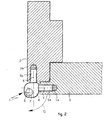
- Fig. 2 is a typical transverse cross sectional view through a door frame 2 and a door plate 3 connected by a hinge assembly 1 according to the present invention.
- the upper hinge body 4 is seen, connected to the door frame 2 by means of bolt 4a that is secured and adjusted into threaded hole 2a of the door frame.
- the middle hinge body 5 (hidden in this figure beneath the upper hinge body 4) is connected to the door plate 3 by means of bolt 5a that is secured and adjusted into threaded hole 3a of the door plate.
- the lower hinge body 6 (hidden in this figure by the upper and middle hinge bodies) is connected to the frame 2 in a similar manner to that of the connection of the upper hinge body 4. The door plate is thus allowed to pivot about the pivot pin 7 between the illustrated closed position, and between an opened position when the plate is moved in the direction of the arrow 10.
- Fig. 3 is an isometric exploded view of a "three part" hinge assembly according to the preferred embodiment of the present invention, comprising eight components as they are spatially configured prior to assembling them into one integral hinge assembly.
- the hinge assembly is comprised of (a) three hinge bodies: an upper hinge body 4, a middle hinge body 5, and a lower hinge body 6; (b) three bolts 4a, 5a, and 6a; (c) pivot pin 7; and (d) a securing screw 8.
- Each of the three hinge bodies is provided with a first (vertical) crossing hole 4c, 5c and 6c, respectively, through which the pivot pin 7 can be inserted.
- Each of the three hinge bodies is further provided with a second (horizontal) crossing hole 4b, 5b and 6b, respectively, through which the bolts 4a, 5a and 6a can be inserted.
- first (vertical) and the second (horizontal) crossing holes of each hinge body 4, 5, 6 are partially intersecting one another forming a junction thereof.
- the intersection point of the first and the second crossing holes can be observed through the first (vertical) crossing hole 4c, 6c of the upper and of the lower hinge bodies 4, 6 and is marked 4d in the upper hinge body 4, and 6d in the lower hinge body 6.
- a similar intersection point exists in the middle hinge body 5 as well, but cannot be observed in Figure 3. It is seen, however, through the cross sectional view illustrated by Figure 4 (see detail 5d of Figure 4).
- the bolts 4a, 5a and 6a are intended to pass respectively through the second crossing holes 4b, 5b and 6b of the three hinge bodies 4, 5, 6.
- Each of the bolts 4a, 5a, 6a has a radial groove 11 near the bolt head 12.
- the radial groove 11 consolidates with the first (vertical) crossing hole 4c, 5c, 6c at the partial intersection junction between the first and the second crossing holes, to form free passageway for the pivot pin 7.
- placement of the pivot pin 7 inside the first crossing hole 4c, 5c, 6c and through the passage provided by the radial groove 11 captures the respective bolt inside the second (horizontal) crossing hole 4b, 5b, 6b without letting it move along the hole.
- the pivot pin 7 In order to prevent the pivot pin 7 from slipping off the hinge bodies 4, 5, 6 during continuous use of the door, it is provided with a recess 7a intended to be positioned opposite the threaded aperture 4e of the upper hinge body 4.
- the securing screw 8 can be screwed inside the aperture 4e until its distal end is stopped by the body of the pivot pin 7 inside the recess 7a.
- the distal end of the securing screw 8 reaches inside the recess 7a, escape of the pivot pin 7 off the first crossing hole 4c, 5c, 6c is prevented.
- the screw 8 is not used and the recess 7a is not made, but a pin 7 is used having a widening in its upper portion, which is clamped through interference against the walls of the vertical hole 4c of the hinge body 4.
- the pivot pin 7 is provided with a head 7b having a greater diameter then that of the pin 7 itself, such that when the wide head 7b is brought to a contact with the top surface of the upper hinge body 4 the recess 7a reaches an appropriate height inside the first crossing hole 4c to face the aperture 4e.
- Each of the three bolts 4a, 5a and 6a is also provided with a widening 13, for facilitating its proper positioning inside the respective second (horizontal) crossing hole 4b, 5b, 6b.
- a widening 13 engages a matching narrowing at the distal end of the hole 4b, 5b, 6b (see for example detail 4f in Figure 5) which prevents a further movement of the bolt 4a, 5a, 6a inside the hole 4b, 5b, 6b.
- the bolt reaches such position, its radial groove 11 consolidates with the first (vertical) crossing hole 4c, 5c, 6c, thus creating free passageway for the pivot pin 7.
- Fig. 4 is an isometric view of the middle hinge body 5 of the hinge assembly 1 of Figure 3, with a partial cross sectional view along its vertical crossing hole 5c, through which the partial intersection junction 5d between the first crossing hole 5c and between the second crossing hole 5b can be observed.
- Fig. 5 is an isometric view over a horizontal cross section through the upper hinge body 4 of the hinge assembly 1 of Figure 3.
- a first crossing hole 4c adapted to receiving the pivot pin (see detail 7 of Figure 3) is partially intersecting a second crossing hole 4b through which a bolt (see detail 4a of Figure 3) is to be inserted.
- the second crossing hole 4b has a narrowing 4f at its distal end, which is useful for limiting the insertion of the bolt to a predetermined measure.
- the bolt can pass through the narrowing 4f until its widening (see detail 13 of Figure 3) reaches and contacts the narrowing 4f and blocked thereby.
- FIG. 6 is an isometric view over the assembled hinge assembly of Figure 3, with horizontal cross section views through its upper hinge body 4 and through its pivot pin 7.
- tearing forces that may act on the hinge 1 through a pressure exerted on the door plate 3 in a direction opposite to that indicated by the arrow 15 shall be resisted by both the reacting force between narrowing 4f and bolt widening 13, and the reacting force between the body of the pivot pin 7 and bolt head 12. Forces acting on the hinge in the direction of arrow 15 shall be resisted by the reacting forces between the body of pivot pin 7 and the bolt body 16.
- Fig. 7 is an isometric view over the assembled hinge assembly of Figure 3, with a partial cross sectional view along the first (vertical) crossing holes of its three hinge bodies 4, 5 and 6.
- pivot pin 7 can be positioned properly inside the vertical crossing holes 4c, 5c, 6c, by inserting it from the upper hinge body 4 downwardly, until its wide head 7b is stopped by the top surface of the upper hinge body 4.
- the pin recess 7a faces the threaded hole (see detail 4e of Figure 3), which is missing in this Figure due to the cross section made in the hinge bodies 4, 5, 6.
- FIG. 7 is an isometric view over the assembled hinge assembly of Figure 3, with a partial cross sectional view along the first (vertical) crossing holes of its three hinge bodies 4, 5 and 6.
- Fig. 8 is an isometric view over the assembled hinge assembly of Figure 3.
- the hinge bodies illustrated in the preferred embodiment illustrated by these figures are of two sizes, namely the middle hinge body 5 is of a greater height dimension comparing to the height dimension of the upper 4 and lower 6 hinge bodies, it should be appreciated that they could be designed in other proportions as a matter of design considerations, without departing from the scope of the present invention.
- the middle hinge body 5 is of similar dimensions as the upper and the lower ones 4, 6, thus a triplicate of the same component can be produced and serve as the three hinge bodies 4a, 5a, 6a, which may help in reducing manufacturing costs.
- the whole hinge 1 may be produced from only three principal components: (a) pivot pin; (b) hinge body (in the required number of units to be nested on the pivot pin); and (c) securing element.
- the hinge bodies 4, 5, 6 may be provided with a matching threaded aperture in order to keep uniformity of the hinge body as could be desired from logistic perspective, (although only one aperture of the three bodies will be used in order to secure the pivot pin).
- the pivot pin 7 can be designed to protrude a few millimeters from below the lower hinge body 6 and be secured by a grooved springy disk to be mounted on its bottom end by pressure.
- pivot pin 7 Another option is to provide the pivot pin 7 with radial groove near its bottom end, adapted to receiving an omega shaped securing spring. Another option is to provide the pivot pin 7 with a crossing aperture near its bottom end, adapted to receiving a securing wire, peg, or split securing pin.
- Fig. 9 is an isometric view over the assembled hinge assembly 1 of Figure 8, taken from an opposite direction.
- the hinge assembly 1 as depicted in this Figure, as well is in the preceding ones, is for use of doors who open to the left. However and as can be appreciated, it may be assembled for use of right open doors in a similar manner. The only change would be that the middle hinge body will be assembled in an up-side-down orientation to the depicted one, which will result in that the bolt 5a will protrude to the opposite direction (i.e. in 180 degrees to its currently depicted orientation).
- Fig. 10 shows a first variant, wherein between the upper hinge body and the middle hinge body 4, 5 and between the middle and lower hinge body 5, 6, a respective bushing 17 is inserted, coaxial with the pivot pin 7, advantageously made of self-lubricating material, which reduces the friction and allows a better reciprocal sliding between two adjacent hinge bodies 4, 5, 6.
- Fig. 11 shows a second variant, wherein the bushing 17 comprises two parts 17a, 17b, coupled together through screwing, so as to allow to adjust the distance between two adjacent hinge bodies 4, 5, 6 and hence of the overall height of the hinge assembly 1 along the hinging axis I.
- This embodiment allows to adjust the hinge assembly 1 along the third axis too, and in this case too the adjustment can be performed without needing to dismantle the door plate 3, as already described with reference to the axes X and Y.
- Fig. 12 shows a condition of the hinge assembly 1 wherein the bolts 4a, 5a, 6a are parallel to each other; in this condition the hinge assembly 1 allows to articulate, for example a door plate with respect to a frame between a closed position, in which the plate is parallel to the frame, and an open position, in which the plate 3 is rotated by the desired angle with respect to the frame 2.
- each of the hinge bodies 4, 5, 6 is provided with a hole 19, substantially parallel to the first vertical crossing holes 4c, 5c, 6c and therefore to the hinging axis I, which interferes with the horizontal holes 4c, 5c, 6c into which the bolts 4a, 5a, 6a are inserted.
- a small retaining cylinder can be inserted, for example made of plastic, which retains the relative bolt 4a, 5a, and 6a through interference after the first insertion inside the relative hinge body 4, 5 and 6.
- the hinge assembly according to the present invention is advantageous in that it can be produced from a minimum number of components; it can be assembled and adjusted by a door technician in field conditions without disassembling the hinge 1 from the relative elements 2, 3; it could be adapted to the use of a right open door or of a left open door in field conditions; it is modular in that the same components may be used for assembling different number of hinge bodies nested on pivot pins having appropriate dimensions, thus creating hinges of different load capacities from the same basic components; it is massive and lasting since all of its components are held together by the pivot pin itself which is normally made massive due its heavy duty mission for supporting the door.
- the hinge assembly is made of steel, for example drawn or sintered. However, it can be manufactured from other metals or alloys as well, as may be allowed according to specific applications to which it can be directed. According to various embodiments of the present invention, and due to the massive construction of the hinge assembly which its entire parts are held together by the massive pivot pin element, the hinge assembly may be constructed even of plastic materials or of composite materials, and still provide reasonable load capacities for various applications. Accordingly, the manufacturing of a hinge according to this invention is not limited to specific materials, and whatever material it is made from, it should be considered within the scope of the present invention.
Abstract
Description
- The present invention relates to the field of adjustable hinges.
- In order to allow for optimal adaptation between hinged plates (e.g. doors, windows, folding walls or the like) and between the frames or walls to which they are hinged, there is a need in adjustment arrangements that will allow to compensate against inaccuracies that may occur between hinged parts during their construction or use. Such adjustment arrangements may be directed to allow for zeroing the distance between the hinged device and the frame or wall to which it is hinged, i.e. such that both parts will stand completely parallel to each other (i.e. with zero degree angle between their planes) in their closed state. Furthermore such adjustment arrangements may be directed to allow for bringing the level of the hinged plate even with that of the wall or frame to which it is hinged, and for bringing the hinged plate centralized between the sides of the frame.
- In one type of adjustable hinges of prior art, the bolts which connect the hinge to the hinged parts form immovable joint with the hinge bodies from which they protrude. Accordingly, an adjustment of the gap between the hinge body and the frame or wall to which it is hinged can be achieved by rotating the bolt with the entire hinge body to which it is immovably joint, clockwise or counterclockwise inside the threaded hole to which it is screwed. This could be performed only when the hinge bodies are separated from one another (i.e. the hinged is in its disassembled state), and the adjustment is limited to complete (integer) rotations of the bolt.
- Incomplete rotation will result in an inclined orientation of the hinge body, which is inappropriate for reassembling of the hinge bodies all together after completion of the adjustment.
- In another type of adjustable hinges of prior art, the bolts which connect the hinge to the hinged parts have free infinite rotation in the hinge bodies from which they protrude, thus allow for fine and accurate tuning. Such hinge types consist however of a larger number of separate parts, including the hinge bodies, the bolts, and bolt holder parts that are the elements capturing the bolts in a fixed predetermined location inside the hinge bodies, while allowing their free rotation (without changing their said predetermined location) for adjusting the gap between the hinge and the plate or the frame to which it is attached.
- It is therefore an object of the present invention to reduce the number of components from which an adjustable hinge is assembled, and still allow for fine and accurate tuning of the gap between the hinge and the plate or frame to which it is connected. Such reduction in the number of component will allow for facilitating the assemblage of the hinge and for reducing its production costs.
- Another object of the present invention is to allow to adjust the hinge, also on all three axes, leaving the hinge assembled on the plate and frame elements which are hinged together.
- The present invention relates to an adjustable hinge assembly comprising at least two hinge bodies, each provided with at least a respective bolt to attach to the relative element to be hinged, whether it be a fixed part such as a frame or a wall, or a movable part such as a door, a plate or suchlike.
- Each bolt defines a respective fixing axis for the relative element to be hinged.
- The hinge bodies are disposed one on the other and are hinged to each other on a hinging axis.
- According to a characteristic of the present invention, said hinging axis does not intersect said fixing axes but is offset or misaligned with respect to them.
- To be more exact, when the elements to be hinged are in a closed position, and the fixing axes of the at least two hinge bodies substantially form a right angle between them, the hinging axis is in an outer position with respect to said angle.
- This configuration allows to have a hinging axis displaced towards the outside with respect to the elements to be hinged when the latter are in the closed position, with the fixing axes of the bolts disposed closer to the elements to be hinged compared with normal hinges in which the hinging axis intersects the fixing axes.
- This allows to use the hinge with elements hinged to each other, for example a door frame and plate, having a relatively thin thickness while still ensuring an extensive reciprocal rotation of said parts.
- According to another characteristic of the present invention, the hinge assembly comprises a hinge pin (will be referred to hereinafter also as "pivot pin"); at least two hinge bodies at least one of which having (a) a first (vertical) crossing hole, which defines said hinging axis, of a diameter matching that of the pivot pin; (b) at least one second (horizontal) crossing hole (of a predetermined diameter adapted to receiving a connecting bolt) which defines said fixing axis and is disposed in an orientation perpendicular to that of the first one.
- In a first embodiment of the invention, the first vertical crossing hole in which the pin is inserted does not intersect the second horizontal crossing hole in which the fixing bolt is inserted.
- In another embodiment, the first and the second crossing holes are partially intersecting one another forming a junction there between; in this case, the bolt for positioning inside the second (horizontal) crossing hole has a radial groove at a predetermined location along its length (according to the preferred embodiments the location of the radial groove is next to the head of the bolt); said groove when brought inside the second crossing hole into alignment with the first crossing hole, makes room for the pivot pin to pass through the first crossing hole and across the bolt, thus capturing the bolt which then becomes incapable of linear movement along the second crossing hole, without losing its ability to rotate (thus enabling adjustment of the gap between the hinge body and between the plate or the frame to which it is intended to be secured).
- According to the present invention a plurality of hinge bodies with a plurality of bolts may be nested along one pivot pin, thus forming a multi part hinge with connecting bolts that can be securing the hinge bodies to the hinged plate or to the frame, and tuned to maintain the hinge body in a desired distance from the plate or from the frame to which it is connected. The pivot pin is provided in a length appropriate for holding a predetermined number of hinge bodies including washers (if so wished or so required to eliminate direct friction between hinge bodies or between hinge bodies and the head of the hinge pin) in between, and including (if so wished or so required) closure or stopper means for preventing escape of the pivot pin from the hinge bodies, for keeping the hinge bodies together, or for facilitating the positioning of the pivot pin during assembling the hinge from its separate parts. Such closure or stopper means may comprise any arrangement (e.g. hinge cotter pin) using for securing pin ends as known in the art/, or equivalent. As will be further described in detail, the means for securing the pivot pin from escaping the hinge are not necessarily located at the end of the pivot pin, thus not necessarily requiring protrusion of the pivot pin beyond the upper of lower ends of the hinge bodies.
- The term 'rotation-governing end' relates to a bolt end having a form that enables rotating the bolt using a screwdriver, key (e.g. "Ellen key"), or other tool having a matching form.
- According to one of the preferred embodiments of the present invention the hinge assembly comprises three hinge bodies each having a first and a second crossing holes intersecting one another forming a junction there between, three bolts, and one pivot pin. It is preferably comprising also at least one pin securing element (to prevent the pivot pin escaping from its position during continuous use).
- According to several preferred embodiments the hinge assembly is supplied from its producer to the customer divided to its parts in a disassembled state, wherein the end user (or technician) may assemble it immediately prior to putting it to use.
- According to a variant, each hinge body comprises means to secure, for example through interference, the relative fixing bolt inside it after insertion in the relative hole; the hinge can thus be pre-assembled, for example for storage and transport, limiting to a minimum the number of different pieces, which are reduced to the hinge bodies, normally three, with the relative pre-assembled bolt, and the pin. In this pre-assembled configuration, the assembly of the hinge by the final user is extremely facilitated.
- The present invention further relates to a method for assembling adjustable hinges, comprising (a) inserting bolts having radial groove at a location along their length into horizontal, or second, crossing holes made in corresponding hinge bodies; (b) bringing the radial groove of each bolt into alignment with a vertical, or first, crossing hole made in the respective hinge body and partially intersects the horizontal crossing hole; (c) nesting the hinge bodies along a pivot pin by inserting the pivot pin through the vertical crossing hole of each hinge body one next to another and across the bolts through their radial groove thus capturing the bolts which then become incapable of linear movement along the horizontal, or second, second crossing holes without losing their ability to rotate.
- In order to understand the invention and to see how it may be carried out in practice, a preferred embodiment will now be described, by way of non-limiting example only, with reference to the accompanying drawings, in which:
- Fig. 1
- is an isometric view of a preferred embodiment of a "three part" hinge assembly according to the present invention, prepared for connecting between a door frame and a door plate.
- Fig. 2
- is a typical transverse cross sectional view through a door frame and a door plate connected by a hinge assembly according to the present invention.
- Fig. 3
- is an isometric exploded view of a "three part" hinge assembly according to the preferred embodiment of the present invention, comprising eight components as they are spatially configured prior to assembling them into one integral hinge assembly.
- Fig. 4
- is an isometric view of the middle hinge body of the hinge assembly of Figure 3, with a partial cross sectional view along its vertical crossing hole.
- Fig. 5
- is an isometric view over a horizontal cross section through the upper hinge body of the hinge assembly of Figure 3.
- Fig. 6
- is an isometric view over the assembled hinge assembly of Figure 3, with horizontal cross section views through its upper hinge body and through its pivot pin.
- Fig. 7
- is an isometric view over the assembled hinge assembly of Figure 3, with a partial cross sectional view along the vertical crossing holes of its three hinge bodies.
- Fig. 8
- is an isometric view over the assembled hinge assembly of Figure 3.
- Fig. 9
- is an isometric view over the assembled hinge assembly of Figure 8, taken from an opposite direction.
- Fig. 10
- is a lateral view of a first variant of the hinge assembly of Figure 1.
- Fig. 11
- is a lateral view of a second variant of the hinge assembly of Figure 10.
- Fig. 12
- is a plane view of the hinge assembly of Figure 10.
- Fig. 13
- is a plane view of the hinge assembly of Figure 12 assembled on a door plate hinged to a door frame.
- Fig. 1 is an isometric view of a preferred embodiment of a "three part"
hinge assembly 1 according to the present invention, prepared for the connection between adoor frame 2 and adoor plate 3. - In the case shown here, the
hinge assembly 1 is comprised of (a) three hinge bodies: anupper hinge body 4, amiddle hinge body 5, and alower hinge body 6; (b) threebolts pivot pin 7; and (d) a securingscrew 8 intending to prevent escape of thepivot pin 7 from the hinge bodies. The upper and thelower hinge bodies door frame 2 and themiddle hinge body 5 is intended to be secured to thedoor plate 3 by rotating thebolts holes bolts bolts - After securing the
hinge bodies door frame 2 and to thedoor plate 3, the gaps between thehinge assembly 1 and between thedoor frame 2 and thedoor plate 3 could be adjusted in the directions pointed out by arrows A and B, by rotating thebolts door plate 3 to its optimal position respective to thedoor frame 2. - In one embodiment of the invention, and according to its main characteristic, the
hinge bodies door frame 2 and thedoor plate 3 in the closed position, and substantially at a right angle, slightly rounded, on the inner side of the frame/plate. - The first (vertical) crossing holes 4c, 5c, 6c define an axis, or hinging axis I, which does not intersect the axes X, Y, orthogonal to each other, of the fixing
bolts elements - This configuration allows to use the
hinge assembly 1 also with relativelynarrow door frames 2 andplates 3, while still ensuring a secure assembly and an ample rotation of thedoor plate 3 with respect to thedoor frame 2. - In the hinge assembly according to the invention, because the assembly axes of the bolts and pins are offset, the
bolts pin 7 and theirheads 12 protrude from therelative bodies frame 2 and to theplate 3, as will be explained in more detail hereafter, can be carried out without needing to dis-assemble theplate 3 and/or thehinge assembly 1. - Fig. 2 is a typical transverse cross sectional view through a
door frame 2 and adoor plate 3 connected by ahinge assembly 1 according to the present invention. In this figure, theupper hinge body 4 is seen, connected to thedoor frame 2 by means ofbolt 4a that is secured and adjusted into threadedhole 2a of the door frame. The middle hinge body 5 (hidden in this figure beneath the upper hinge body 4) is connected to thedoor plate 3 by means ofbolt 5a that is secured and adjusted into threadedhole 3a of the door plate. The lower hinge body 6 (hidden in this figure by the upper and middle hinge bodies) is connected to theframe 2 in a similar manner to that of the connection of theupper hinge body 4. The door plate is thus allowed to pivot about thepivot pin 7 between the illustrated closed position, and between an opened position when the plate is moved in the direction of thearrow 10. - Fig. 3 is an isometric exploded view of a "three part" hinge assembly according to the preferred embodiment of the present invention, comprising eight components as they are spatially configured prior to assembling them into one integral hinge assembly. The hinge assembly is comprised of (a) three hinge bodies: an
upper hinge body 4, amiddle hinge body 5, and alower hinge body 6; (b) threebolts pivot pin 7; and (d) a securingscrew 8. Each of the three hinge bodies is provided with a first (vertical) crossinghole pivot pin 7 can be inserted. Each of the three hinge bodies is further provided with a second (horizontal) crossinghole bolts - In the embodiment shown in the figures, the first (vertical) and the second (horizontal) crossing holes of each
hinge body hole lower hinge bodies upper hinge body lower hinge body 6. A similar intersection point exists in themiddle hinge body 5 as well, but cannot be observed in Figure 3. It is seen, however, through the cross sectional view illustrated by Figure 4 (seedetail 5d of Figure 4). Thebolts second crossing holes hinge bodies bolts radial groove 11 near thebolt head 12. When thebolt hole respective hinge body radial groove 11 consolidates with the first (vertical) crossinghole pivot pin 7. In turn, placement of thepivot pin 7 inside thefirst crossing hole radial groove 11 captures the respective bolt inside the second (horizontal) crossinghole bolt door frame 2 or at the door plate 3) or for adjusting the gap between the hinge and between the frame or plate to which it is connected. - In order to prevent the
pivot pin 7 from slipping off thehinge bodies recess 7a intended to be positioned opposite the threadedaperture 4e of theupper hinge body 4. When thepivot pin 7 is in positioned inside thefirst crossing hole 4c, the securingscrew 8 can be screwed inside theaperture 4e until its distal end is stopped by the body of thepivot pin 7 inside therecess 7a. When the distal end of the securingscrew 8 reaches inside therecess 7a, escape of thepivot pin 7 off thefirst crossing hole - According to a variant not shown here, the
screw 8 is not used and therecess 7a is not made, but apin 7 is used having a widening in its upper portion, which is clamped through interference against the walls of thevertical hole 4c of thehinge body 4. This solution simplifies the operations to produce thehinge body 1 and further reduces the number of its components. - In order to facilitate appropriate positioning of the
pivot pin 7 inside the first (vertical) crossinghole 4c thepivot pin 7 is provided with ahead 7b having a greater diameter then that of thepin 7 itself, such that when thewide head 7b is brought to a contact with the top surface of theupper hinge body 4 therecess 7a reaches an appropriate height inside thefirst crossing hole 4c to face theaperture 4e. - Each of the three
bolts hole bolt second crossing hole hole example detail 4f in Figure 5) which prevents a further movement of thebolt hole radial groove 11 consolidates with the first (vertical) crossinghole pivot pin 7. - Fig. 4 is an isometric view of the
middle hinge body 5 of thehinge assembly 1 of Figure 3, with a partial cross sectional view along itsvertical crossing hole 5c, through which thepartial intersection junction 5d between thefirst crossing hole 5c and between thesecond crossing hole 5b can be observed. - Fig. 5 is an isometric view over a horizontal cross section through the
upper hinge body 4 of thehinge assembly 1 of Figure 3. Afirst crossing hole 4c adapted to receiving the pivot pin (seedetail 7 of Figure 3) is partially intersecting asecond crossing hole 4b through which a bolt (seedetail 4a of Figure 3) is to be inserted. Thesecond crossing hole 4b has a narrowing 4f at its distal end, which is useful for limiting the insertion of the bolt to a predetermined measure. The bolt can pass through the narrowing 4f until its widening (seedetail 13 of Figure 3) reaches and contacts the narrowing 4f and blocked thereby. When the bolt is blocked by the narrowing 4f, its radial groove (seedetail 11 of Figure 3) consolidates with the first (vertical) crossinghole 4c, thus forming a passageway for the pivot pin (detail 7 of Figure 4). When the pivot pin is in position inside thefirst crossing hole 4c, it can be secured to prevent its removal, by means of a securing screw (detail 8 of Figure 3) tightened through threadedaperture 4e into a recess (detail 7a of Figure 3) made in the body of the pivot pin. Fig. 6 is an isometric view over the assembled hinge assembly of Figure 3, with horizontal cross section views through itsupper hinge body 4 and through itspivot pin 7. In this figure it can be seen how the distal end of securingscrew 8 contacts the body of thepivot pin 7 inside therecess 7a for preventing removal of the pivot pin from the hinge bodies. In this Figure it can further be observed howpivot pin 7 passes through theradial groove 11 ofbolt 4a, thus capturing the bolt and preventing its linear movement inside the second (horizontal) crossinghole 4b of theupper hinge body 4. Actually, a linear movement of thebolt 4a in the direction indicated byarrow 15 is prevented by the narrowing 4f at the distal end of thesecond crossing hole 4b that blocks the corresponding widening 13 of the bolt from further movement in that direction. Accordingly, tearing forces that may act on thehinge 1 through a pressure exerted on thedoor plate 3 in a direction opposite to that indicated by thearrow 15 shall be resisted by both the reacting force between narrowing 4f and bolt widening 13, and the reacting force between the body of thepivot pin 7 andbolt head 12. Forces acting on the hinge in the direction ofarrow 15 shall be resisted by the reacting forces between the body ofpivot pin 7 and thebolt body 16. - Fig. 7 is an isometric view over the assembled hinge assembly of Figure 3, with a partial cross sectional view along the first (vertical) crossing holes of its three
hinge bodies pivot pin 7 can be positioned properly inside the vertical crossing holes 4c, 5c, 6c, by inserting it from theupper hinge body 4 downwardly, until itswide head 7b is stopped by the top surface of theupper hinge body 4. In such position thepin recess 7a faces the threaded hole (seedetail 4e of Figure 3), which is missing in this Figure due to the cross section made in thehinge bodies pivot pin 7 passes through the radial recesses existing behind theheads 12 of the threebolts - Fig. 8 is an isometric view over the assembled hinge assembly of Figure 3. Although the hinge bodies illustrated in the preferred embodiment illustrated by these figures are of two sizes, namely the
middle hinge body 5 is of a greater height dimension comparing to the height dimension of the upper 4 and lower 6 hinge bodies, it should be appreciated that they could be designed in other proportions as a matter of design considerations, without departing from the scope of the present invention. For example, according to another preferred embodiment of the present invention, themiddle hinge body 5 is of similar dimensions as the upper and thelower ones hinge bodies whole hinge 1 may be produced from only three principal components: (a) pivot pin; (b) hinge body (in the required number of units to be nested on the pivot pin); and (c) securing element. - In case the securing element is a screw (
e.g. detail 8 of Figure 3), all thehinge bodies pivot pin 7 can be designed to protrude a few millimeters from below thelower hinge body 6 and be secured by a grooved springy disk to be mounted on its bottom end by pressure. Another option is to provide thepivot pin 7 with radial groove near its bottom end, adapted to receiving an omega shaped securing spring. Another option is to provide thepivot pin 7 with a crossing aperture near its bottom end, adapted to receiving a securing wire, peg, or split securing pin. - Fig. 9 is an isometric view over the assembled
hinge assembly 1 of Figure 8, taken from an opposite direction. Thehinge assembly 1 as depicted in this Figure, as well is in the preceding ones, is for use of doors who open to the left. However and as can be appreciated, it may be assembled for use of right open doors in a similar manner. The only change would be that the middle hinge body will be assembled in an up-side-down orientation to the depicted one, which will result in that thebolt 5a will protrude to the opposite direction (i.e. in 180 degrees to its currently depicted orientation). - Fig. 10 shows a first variant, wherein between the upper hinge body and the
middle hinge body lower hinge body respective bushing 17 is inserted, coaxial with thepivot pin 7, advantageously made of self-lubricating material, which reduces the friction and allows a better reciprocal sliding between twoadjacent hinge bodies - Fig. 11 shows a second variant, wherein the
bushing 17 comprises twoparts adjacent hinge bodies hinge assembly 1 along the hinging axis I. - This embodiment allows to adjust the
hinge assembly 1 along the third axis too, and in this case too the adjustment can be performed without needing to dismantle thedoor plate 3, as already described with reference to the axes X and Y. - Fig. 12 shows a condition of the
hinge assembly 1 wherein thebolts hinge assembly 1 allows to articulate, for example a door plate with respect to a frame between a closed position, in which the plate is parallel to the frame, and an open position, in which theplate 3 is rotated by the desired angle with respect to theframe 2. - In figures 12 and 13 a variant is also shown in which each of the
hinge bodies hole 19, substantially parallel to the first vertical crossing holes 4c, 5c, 6c and therefore to the hinging axis I, which interferes with thehorizontal holes bolts - Inside said holes 19 a small retaining cylinder can be inserted, for example made of plastic, which retains the
relative bolt relative hinge body - In this way, it is possible to achieve a pre-assembly of each hinge body with the relative fixing bolt, which facilitates both storage and transport operations, and also the assembly operation by the final user.
- Other embodiments, however, can also be achieved for the pre-assembly of the bolt with respect to the hinge body, for example a protrusion made on the wall of the
horizontal hole - As can be appreciated, the hinge assembly according to the present invention is advantageous in that it can be produced from a minimum number of components; it can be assembled and adjusted by a door technician in field conditions without disassembling the
hinge 1 from therelative elements - According to the preferred embodiment the hinge assembly is made of steel, for example drawn or sintered. However, it can be manufactured from other metals or alloys as well, as may be allowed according to specific applications to which it can be directed. According to various embodiments of the present invention, and due to the massive construction of the hinge assembly which its entire parts are held together by the massive pivot pin element, the hinge assembly may be constructed even of plastic materials or of composite materials, and still provide reasonable load capacities for various applications. Accordingly, the manufacturing of a hinge according to this invention is not limited to specific materials, and whatever material it is made from, it should be considered within the scope of the present invention.
- The above and other advantages of the hinge assembly of the present invention lead to a meaningful reduction in the production costs of adjustable hinges, and improve the logistic involved in their stock storage and delivery.
Claims (14)
- Adjustable hinge assembly for hinging a first fixed element (2) and a second movable element (3) and comprising at least two hinge bodies (4, 5, 6), each provided with at least a respective bolt (4a, 5a, 6a) defining a relative fixing axis (X, Y) for the relative fixed (2) or movable (3) element, said hinge bodies (4, 5, 6) being hinged to each other on a hinging axis (I), characterized in that said hinging axis (I) does not intersect said fixing axes (X, Y).
- Adjustable hinge assembly according to claim 1,
characterized in that said hinging axis (I) is disposed outside with respect to the angle (α) defined by said fixing axes (X, Y) in the closed position of the relative hinged elements (2, 3). - Adjustable hinge assembly according to claim 1 or 2, further comprising a pivot pin (7) defining said hinging axis (I); at least one of said two hinge bodies (4, 5, 6) having a first crossing hole (4c, 5c, 6c) of a diameter matching that of the pivot pin (7); at least one second crossing hole (4b, 5b, 6b) in an orientation perpendicular to that of the first one and defining said fixing axis (X, Y), characterized in that the first and the second crossing holes (4c, 4b; 5c, 5b; 6c, 6b) are partially intersecting one another forming a junction (4d, 5d, 6d) there between.
- Adjustable hinge assembly according to claim 3,
characterized in that said bolt (4a, 5a, 6a) is positioned inside the second crossing hole (4b, 5b, 6b) and has a radial groove (11) at a predetermined location along its length; said radial groove (11), when brought inside the second crossing hole (4b, 5b, 6b) into alignment with the first crossing hole (4c, 5c, 6c), makes room for the pivot pin (7) to pass through the first crossing hole (4c, 5c, 6c) and across the bolt (4a, 5a, 6a), thus capturing the bolt (4a, 5a, 6a), which then becomes incapable of linear movement along the second crossing hole (4b, 5b, 6b) without losing its ability to rotate. - Adjustable hinge assembly according to any claim hereinbefore, characterized in that said pivot pin (7) is secured to at least one of said hinge bodies (4, 5, 6) by means of a securing element (8) able to be inserted in a corresponding seating (4e) made on the respective hinge body (4) and in a recess (7a) made in the pin (7).
- Adjustable hinge assembly according to claim 2, 3 or 4, characterized in that said pin (7) comprises, in an upper portion, a widening able to cooperate with a segment of inner wall of the crossing hole of one of the end hinge bodies (4 or 6) in order to secure through interference said pin (7) to the corresponding hinge body (4 or 6).
- Adjustable hinge assembly according to any one of the preceding claims, characterized in that between at least two of said hinge bodies (4, 5, 6) at least a spacer element (17) is inserted, with an anti-friction function.
- Adjustable hinge assembly according to claim 7,
characterized in that said spacer element (17) is of the self-lubricating type. - Adjustable hinge assembly according to claim 7,
characterized in that said spacer element (17) has an adjustable height to allow to adjust the distance between two adjacent hinge bodies (4, 5, 6). - Adjustable hinge assembly according to any one of the preceding claims, characterized in that it comprises three hinge bodies (4, 5, 6) each having a first and a second crossing holes (4c, 4b, 5c, 5b, 6c, 6b) intersecting one another forming a junction (4d, 5d, 6d) there between, three bolts (4a, 5a, 6a), and one pivot pin (7).
- Adjustable hinge assembly according to any one of the preceding claims, characterized in that it comprises three hinge bodies (4, 5, 6) each having a first and a second crossing holes (4c, 4b, 5c, 5b, 6c, 6b) intersecting one another forming a junction (4d, 5d, 6d) there between, three bolts (4a, 5a, 6a), one pivot pin (7), and at least one pin securing element (8).
- Adjustable hinge assembly according to any one of the preceding claims, characterized in that it is supplied to a customer divided to its parts in a disassembled state.
- Adjustable hinge assembly according to any one of the preceding claims, characterized in that it comprises means for pre-assembling the bolt (4a, 5a, 6a) to the respective body (4, 5, 6).
- Method for assembling adjustable hinges (1),
characterized in that it comprises the following steps: (a) inserting bolts (4a, 5a, 6a) having radial groove (11) at a location along their length into respective horizontal crossing holes (4b, 5b, 6b) made in corresponding hinge bodies (4, 5, 6); (b) bringing the radial groove (11) of each bolt (4a, 5a, 6a) into alignment with a vertical crossing hole (4c, 5c, 6c) made in the respective hinge body (4, 5, 6) and partially intersecting the horizontal crossing hole (4b, 5b, 6b); (c) nesting the hinge bodies (4, 5, 6) along a pivot pin (7) by inserting the pivot pin (7) through the vertical crossing holes (4c, 5c, 6c) of each hinge body (4, 5, 6) one next to another and across the bolts (4a, 5a, 6a) through their radial groove (11) thus capturing the bolts (4a, 5a, 6a) which then become incapable of linear movement along the horizontal crossing holes (4b, 5b, 6b) without losing their ability to rotate.
Applications Claiming Priority (1)
| Application Number | Priority Date | Filing Date | Title |
|---|---|---|---|
| IL16346104 | 2004-08-11 |
Publications (2)
| Publication Number | Publication Date |
|---|---|
| EP1626146A2 true EP1626146A2 (en) | 2006-02-15 |
| EP1626146A3 EP1626146A3 (en) | 2006-07-26 |
Family
ID=35395790
Family Applications (1)
| Application Number | Title | Priority Date | Filing Date |
|---|---|---|---|
| EP05107208A Withdrawn EP1626146A3 (en) | 2004-08-11 | 2005-08-04 | Hinge assembly |
Country Status (2)
| Country | Link |
|---|---|
| EP (1) | EP1626146A3 (en) |
| RU (1) | RU2005125519A (en) |
Cited By (3)
| Publication number | Priority date | Publication date | Assignee | Title |
|---|---|---|---|---|
| EP2020475A1 (en) * | 2007-07-31 | 2009-02-04 | Alessandro Barca | Adjustable hinge for doors and windows |
| CN107916853A (en) * | 2017-12-21 | 2018-04-17 | 重庆金华电器成套有限公司 | A kind of distributing box and its hinge |
| GB2553545B (en) * | 2016-09-07 | 2021-08-11 | Kohler Mira Ltd | Door hinge |
Citations (2)
| Publication number | Priority date | Publication date | Assignee | Title |
|---|---|---|---|---|
| EP0249945A2 (en) * | 1986-06-18 | 1987-12-23 | Julius Blum Gesellschaft m.b.H. | Door hinge |
| DE19607846C1 (en) * | 1996-03-01 | 1997-05-07 | Heine & Sohn Anuba Beschlaege | Hinge for door or window in building |
-
2005
- 2005-08-04 EP EP05107208A patent/EP1626146A3/en not_active Withdrawn
- 2005-08-10 RU RU2005125519/12A patent/RU2005125519A/en not_active Application Discontinuation
Patent Citations (2)
| Publication number | Priority date | Publication date | Assignee | Title |
|---|---|---|---|---|
| EP0249945A2 (en) * | 1986-06-18 | 1987-12-23 | Julius Blum Gesellschaft m.b.H. | Door hinge |
| DE19607846C1 (en) * | 1996-03-01 | 1997-05-07 | Heine & Sohn Anuba Beschlaege | Hinge for door or window in building |
Cited By (3)
| Publication number | Priority date | Publication date | Assignee | Title |
|---|---|---|---|---|
| EP2020475A1 (en) * | 2007-07-31 | 2009-02-04 | Alessandro Barca | Adjustable hinge for doors and windows |
| GB2553545B (en) * | 2016-09-07 | 2021-08-11 | Kohler Mira Ltd | Door hinge |
| CN107916853A (en) * | 2017-12-21 | 2018-04-17 | 重庆金华电器成套有限公司 | A kind of distributing box and its hinge |
Also Published As
| Publication number | Publication date |
|---|---|
| RU2005125519A (en) | 2007-02-20 |
| EP1626146A3 (en) | 2006-07-26 |
Similar Documents
| Publication | Publication Date | Title |
|---|---|---|
| KR102308744B1 (en) | Variable friction hinge | |
| US9708840B2 (en) | Durable low-vibration long arm hinge apparatus | |
| JP2593272B2 (en) | Return hinge | |
| EP1626146A2 (en) | Hinge assembly | |
| US5826305A (en) | Furniture hinge | |
| US8813309B2 (en) | Roller hinge constructions | |
| EP0789125B1 (en) | Supporting member for a closure element, preferably for a wing of a sliding and folding door | |
| US20020073509A1 (en) | Mechanism and method for adjusting doors | |
| CN101346525A (en) | Furniture hinge | |
| CA2197391A1 (en) | Cam adjusting device for iron fittings for furniture and iron fittings with such device | |
| EP2169163A1 (en) | Height-adjustable hinge | |
| EP1455042B1 (en) | Adjustable hinge for window or door casing | |
| DE4436484A1 (en) | Pivotable curtain walling glazing panel holder | |
| US5143413A (en) | Gate bracket connector with a pair of U-shaped yoke members | |
| US20170074014A1 (en) | Adjustable Hinge For Vertically Hanging Panel | |
| DE4436199C1 (en) | Radius actuator e.g for machinery safety switches | |
| EP0837206B1 (en) | Door hinge for swingingly supporting a door leaf from a door frame | |
| EP2984423B1 (en) | Domestic refrigeration device having a door-closing fitting part | |
| DE102008036151A1 (en) | Hinge strap with a substructure for attachment to a door leaf | |
| JP5401277B2 (en) | Orito | |
| DE202014102474U1 (en) | Adjustable flap bearing | |
| EP4043680B1 (en) | Hinge mounting element | |
| KR20230132006A (en) | Hinge apparatus for door | |
| US11364662B2 (en) | Lifter system with rotational GIB | |
| EP2264269B1 (en) | Adjustable hinge for window or door casing |
Legal Events
| Date | Code | Title | Description |
|---|---|---|---|
| PUAI | Public reference made under article 153(3) epc to a published international application that has entered the european phase |
Free format text: ORIGINAL CODE: 0009012 |
|
| AK | Designated contracting states |
Kind code of ref document: A2 Designated state(s): AT BE BG CH CY CZ DE DK EE ES FI FR GB GR HU IE IS IT LI LT LU LV MC NL PL PT RO SE SI SK TR |
|
| AX | Request for extension of the european patent |
Extension state: AL BA HR MK YU |
|
| PUAL | Search report despatched |
Free format text: ORIGINAL CODE: 0009013 |
|
| AK | Designated contracting states |
Kind code of ref document: A3 Designated state(s): AT BE BG CH CY CZ DE DK EE ES FI FR GB GR HU IE IS IT LI LT LU LV MC NL PL PT RO SE SI SK TR |
|
| AX | Request for extension of the european patent |
Extension state: AL BA HR MK YU |
|
| 17P | Request for examination filed |
Effective date: 20070125 |
|
| 17Q | First examination report despatched |
Effective date: 20070226 |
|
| AKX | Designation fees paid |
Designated state(s): AT BE BG CH CY CZ DE DK EE ES FI FR GB GR HU IE IS IT LI LT LU LV MC NL PL PT RO SE SI SK TR |
|
| GRAP | Despatch of communication of intention to grant a patent |
Free format text: ORIGINAL CODE: EPIDOSNIGR1 |
|
| STAA | Information on the status of an ep patent application or granted ep patent |
Free format text: STATUS: THE APPLICATION IS DEEMED TO BE WITHDRAWN |
|
| 18D | Application deemed to be withdrawn |
Effective date: 20080320 |