EP1624839B1 - A portable hand-operable device for applying pneumatic pressure pulses to an ear canal - Google Patents
A portable hand-operable device for applying pneumatic pressure pulses to an ear canal Download PDFInfo
- Publication number
- EP1624839B1 EP1624839B1 EP04733743A EP04733743A EP1624839B1 EP 1624839 B1 EP1624839 B1 EP 1624839B1 EP 04733743 A EP04733743 A EP 04733743A EP 04733743 A EP04733743 A EP 04733743A EP 1624839 B1 EP1624839 B1 EP 1624839B1
- Authority
- EP
- European Patent Office
- Prior art keywords
- plunger
- diaphragm
- valve means
- pressure
- valve
- Prior art date
- Legal status (The legal status is an assumption and is not a legal conclusion. Google has not performed a legal analysis and makes no representation as to the accuracy of the status listed.)
- Expired - Lifetime
Links
- 210000000613 ear canal Anatomy 0.000 title claims abstract description 16
- 230000000284 resting effect Effects 0.000 claims abstract 6
- 238000007789 sealing Methods 0.000 claims description 8
- 230000000994 depressogenic effect Effects 0.000 claims description 6
- 230000006835 compression Effects 0.000 claims description 5
- 238000007906 compression Methods 0.000 claims description 5
- 230000007423 decrease Effects 0.000 claims description 4
- 238000003825 pressing Methods 0.000 claims description 2
- 239000012530 fluid Substances 0.000 claims 1
- 238000003780 insertion Methods 0.000 claims 1
- 230000037431 insertion Effects 0.000 claims 1
- 208000037265 diseases, disorders, signs and symptoms Diseases 0.000 abstract description 6
- 201000010099 disease Diseases 0.000 abstract description 4
- 206010014020 Ear pain Diseases 0.000 abstract 1
- 210000000883 ear external Anatomy 0.000 description 4
- 210000003454 tympanic membrane Anatomy 0.000 description 4
- 210000000959 ear middle Anatomy 0.000 description 3
- 230000002093 peripheral effect Effects 0.000 description 3
- 208000024891 symptom Diseases 0.000 description 3
- 230000003247 decreasing effect Effects 0.000 description 2
- 208000035475 disorder Diseases 0.000 description 2
- 238000006073 displacement reaction Methods 0.000 description 2
- 210000003027 ear inner Anatomy 0.000 description 2
- 229920001971 elastomer Polymers 0.000 description 2
- 230000002829 reductive effect Effects 0.000 description 2
- 238000012163 sequencing technique Methods 0.000 description 2
- 0 C=CCC(C1=*CCCC1)=C Chemical compound C=CCC(C1=*CCCC1)=C 0.000 description 1
- 206010028813 Nausea Diseases 0.000 description 1
- 208000009205 Tinnitus Diseases 0.000 description 1
- 208000012886 Vertigo Diseases 0.000 description 1
- 208000032625 disorder of ear Diseases 0.000 description 1
- 208000002173 dizziness Diseases 0.000 description 1
- 210000005069 ears Anatomy 0.000 description 1
- 230000000694 effects Effects 0.000 description 1
- 208000005457 endolymphatic hydrops Diseases 0.000 description 1
- 239000003292 glue Substances 0.000 description 1
- 210000003128 head Anatomy 0.000 description 1
- 230000001771 impaired effect Effects 0.000 description 1
- 230000000670 limiting effect Effects 0.000 description 1
- 238000004519 manufacturing process Methods 0.000 description 1
- 239000000463 material Substances 0.000 description 1
- 238000010068 moulding (rubber) Methods 0.000 description 1
- 230000008693 nausea Effects 0.000 description 1
- 230000036961 partial effect Effects 0.000 description 1
- 239000004033 plastic Substances 0.000 description 1
- 229920003023 plastic Polymers 0.000 description 1
- 229910001414 potassium ion Inorganic materials 0.000 description 1
- 230000000717 retained effect Effects 0.000 description 1
- 210000001079 scala tympani Anatomy 0.000 description 1
- 210000001605 scala vestibuli Anatomy 0.000 description 1
- 229920002379 silicone rubber Polymers 0.000 description 1
- 239000004945 silicone rubber Substances 0.000 description 1
- 230000003068 static effect Effects 0.000 description 1
- 231100000886 tinnitus Toxicity 0.000 description 1
- 231100000331 toxic Toxicity 0.000 description 1
- 230000002588 toxic effect Effects 0.000 description 1
- 238000013022 venting Methods 0.000 description 1
- 231100000889 vertigo Toxicity 0.000 description 1
Images



Classifications
-
- A—HUMAN NECESSITIES
- A61—MEDICAL OR VETERINARY SCIENCE; HYGIENE
- A61F—FILTERS IMPLANTABLE INTO BLOOD VESSELS; PROSTHESES; DEVICES PROVIDING PATENCY TO, OR PREVENTING COLLAPSING OF, TUBULAR STRUCTURES OF THE BODY, e.g. STENTS; ORTHOPAEDIC, NURSING OR CONTRACEPTIVE DEVICES; FOMENTATION; TREATMENT OR PROTECTION OF EYES OR EARS; BANDAGES, DRESSINGS OR ABSORBENT PADS; FIRST-AID KITS
- A61F11/00—Methods or devices for treatment of the ears or hearing sense; Non-electric hearing aids; Methods or devices for enabling ear patients to achieve auditory perception through physiological senses other than hearing sense; Protective devices for the ears, carried on the body or in the hand
-
- F—MECHANICAL ENGINEERING; LIGHTING; HEATING; WEAPONS; BLASTING
- F16—ENGINEERING ELEMENTS AND UNITS; GENERAL MEASURES FOR PRODUCING AND MAINTAINING EFFECTIVE FUNCTIONING OF MACHINES OR INSTALLATIONS; THERMAL INSULATION IN GENERAL
- F16K—VALVES; TAPS; COCKS; ACTUATING-FLOATS; DEVICES FOR VENTING OR AERATING
- F16K15/00—Check valves
- F16K15/02—Check valves with guided rigid valve members
- F16K15/021—Check valves with guided rigid valve members the valve member being a movable body around which the medium flows when the valve is open
-
- F—MECHANICAL ENGINEERING; LIGHTING; HEATING; WEAPONS; BLASTING
- F16—ENGINEERING ELEMENTS AND UNITS; GENERAL MEASURES FOR PRODUCING AND MAINTAINING EFFECTIVE FUNCTIONING OF MACHINES OR INSTALLATIONS; THERMAL INSULATION IN GENERAL
- F16K—VALVES; TAPS; COCKS; ACTUATING-FLOATS; DEVICES FOR VENTING OR AERATING
- F16K15/00—Check valves
- F16K15/18—Check valves with actuating mechanism; Combined check valves and actuated valves
-
- A—HUMAN NECESSITIES
- A61—MEDICAL OR VETERINARY SCIENCE; HYGIENE
- A61H—PHYSICAL THERAPY APPARATUS, e.g. DEVICES FOR LOCATING OR STIMULATING REFLEX POINTS IN THE BODY; ARTIFICIAL RESPIRATION; MASSAGE; BATHING DEVICES FOR SPECIAL THERAPEUTIC OR HYGIENIC PURPOSES OR SPECIFIC PARTS OF THE BODY
- A61H9/00—Pneumatic or hydraulic massage
- A61H9/005—Pneumatic massage
-
- A—HUMAN NECESSITIES
- A61—MEDICAL OR VETERINARY SCIENCE; HYGIENE
- A61M—DEVICES FOR INTRODUCING MEDIA INTO, OR ONTO, THE BODY; DEVICES FOR TRANSDUCING BODY MEDIA OR FOR TAKING MEDIA FROM THE BODY; DEVICES FOR PRODUCING OR ENDING SLEEP OR STUPOR
- A61M39/00—Tubes, tube connectors, tube couplings, valves, access sites or the like, specially adapted for medical use
- A61M39/22—Valves or arrangement of valves
Definitions
- the ear piece adaptor 46 has a barbed connection (hidden in Figures) by which it is affixed to the free end 44 of the tube 14.
- the ear piece 48 is removably connected to a protruding tapered nozzle 68 on the ear piece adaptor 46. While the connection between the adaptor 46 and the tube 14 is not intended to be separated, the ear piece 48 is readily removed for replacement.
- the device generates a pressure reduction relative to atmospheric pressure when the user squeezes and releases a diaphragm.
- the effective volume of the device is decreased by a fixed volume.
- a valve seals the chamber port to atmosphere and the chamber size increases resulting in a reduced pressure in both the chamber and the user's ear cavity.
- the user may also elect to partially actuate the device in order to reduce the air pressure by a smaller amount than the maximum provided by the design of the device.
Landscapes
- Engineering & Computer Science (AREA)
- General Engineering & Computer Science (AREA)
- Health & Medical Sciences (AREA)
- Life Sciences & Earth Sciences (AREA)
- Mechanical Engineering (AREA)
- Vascular Medicine (AREA)
- General Health & Medical Sciences (AREA)
- Biophysics (AREA)
- Otolaryngology (AREA)
- Psychology (AREA)
- Biomedical Technology (AREA)
- Heart & Thoracic Surgery (AREA)
- Physics & Mathematics (AREA)
- Animal Behavior & Ethology (AREA)
- Acoustics & Sound (AREA)
- Public Health (AREA)
- Veterinary Medicine (AREA)
- External Artificial Organs (AREA)
- Dental Tools And Instruments Or Auxiliary Dental Instruments (AREA)
- Eye Examination Apparatus (AREA)
- Helmets And Other Head Coverings (AREA)
- Telephone Function (AREA)
- Percussion Or Vibration Massage (AREA)
- Orthopedics, Nursing, And Contraception (AREA)
- Measuring Pulse, Heart Rate, Blood Pressure Or Blood Flow (AREA)
Abstract
Description
- The present invention is directed to a portable device that is useful for the treatment and/or alleviation of symptoms of various ear disorders. It is also directed to the use of such a device.
- Ménière's disease is a disorder of the inner ear. It is characterised by an endolymphatic hydrops of unknown cause. Symptoms consist of disturbed balance, vertigo, impaired hearing and tinnitus. It has been shown that people suffering from Ménière's disease can achieve relief from symptoms of dizziness and nausea through the application of elevated pressure to the outer and middle ear.
- It is theorised that an air pulse, which applies the pressure to the round window of the inner ear may assist in reversing the flow of toxic potassium ions from the scala tympani to the scala vestibuli. The present invention provides a low cost device designed to allow users to apply elevated pressure levels to their own ears in order to achieve such relief.
- The inventor has also recognised that causing a negative change of pressure in the ear canal may be useful in relieving pain arising from other causes, such as unequal pressure between the middle ear and outer ear that occurs during descent of an aircraft. The present invention also provides a device which may achieve such relief.
- A hand-held device for applying pressure to the ear-canal is described in
FR 2 605 516 - The present invention seeks to provide devices that are simple to operate to provide either a positive or negative change in pressure in the ear canal. The invention also seeks to provide such devices that are portable and hand-operable. The device can therefore be carried by a person and easily used, without the assistance of additional mains or battery electric power, whenever relief is sought from various disorders of the ear.
- The invention is directed to a hand-held and hand-operable device for creating a change in pressure in an external ear canal of a person according to the claims.
- The present invention shall now be described with reference to the following drawings which illustrate preferred embodiments of the invention. These drawings are merely illustrative of how the invention may be put into effect so that the specific form and arrangement of the various features as shown is not to be understood as limiting the invention.
-
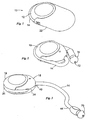
Figure 1 is a perspective view of an air pulsing device according to a first embodiment of the present invention shown with its delivery tube wound onto its case and its cap in place as for storage or transport in a person's pocket. -
Figure 2 is a view of the device inFigure 1 , shown with the storage cap removed. -
Figure 3 is a perspective view of the device inFigure 2 shown with the delivery tube unwound and ready for use. -
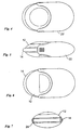
Figure 4 is a top view of the device shown inFigure 1 . -
Figure 5 is a side view of the device shown inFigure 1 . -
Figure 6 is a bottom view of the device shown inFigure 1 . -
Figure 7 is an end view of the device shown inFigure 1 . -
Figure 8 is a side view of portion of the device as shown inFigure 3 . -
Figure 9 is a top view of the portion of the device shown inFigure 8 . -
Figure 10 is a bottom view of the portion of the device shown inFigure 8 . -
Figure 11 is an end view of the portion of the device shown inFigure 8 . -
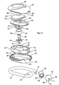
Figure 12 is an exploded view of the device shown inFigure 2 . -
Figure 13 is an enlargement of portion of the exploded view inFigure 12 . -
Figure 14 is a cut-away perspective view of the device according to the first embodiment. -
Figure 15 is an exploded view of an air pulsing device according to a second embodiment of the present invention. -
Figure 16 is a detailed enlargement of portion of the exploded view inFigure 15 . -
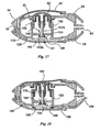
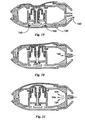
Figures 17 to 21 are cut away views showing the sequence of operations when using the device according to the second embodiment. - Referring to
Figures 1 to 14 , the air-pulsing device 10 illustrated has amain body portion 12 to which is attached aflexible rubber tube 14 at the end of which is anear piece 16 which in use is placed in the patient's ear. Themain body portion 12 is about palm sized and has a generally squashed slightly-ellipsoidal form, so that it is somewhat discus-shaped, although slightly elongated, with aperipheral rim 24. At one of theelongated ends 18 of thebody 12, thetube 14 extends from therim 24. At theopposite end 19 of thebody 12, arounded groove 20 extends along therim 24 and this serves as a locating recess for thetube 14 when it is wound into its storage position as shown inFigure 2 . Thetube 14 wraps along therim 24 of thebody 12 for convenient storage. As shown inFigure 1 , anend cap 22 clips onto theend 18 of the body opposite the groove to cover and protect theear piece 16 and thetube 14 where it extends from thebody 12. - Referring in particular now to
Figures 12 and13 , themain body portion 12 has apressure case 25 formed by fastening together apressure case base 26 and apressure case top 30. Thepressure case base 26 nests into abottom cover 28. Thepressure case top 30 is covered by atop cover 34 which has a largecircular aperture 35 therethrough which is filled by an actuatingpad 32. Therim 31 of the actuatingpad 32 is glued to thetop cover 34 and sandwiched between thepressure case top 30 andtop cover 34. - The
tube 14 is made from flexible silicone rubber and has oneend 40 located onto abarbed nozzle 42 integrally formed on thepressure case base 26. Thenozzle 42 provides a port into thepressure case 25. Thesecond end 44 of thetube 14 is attached to anear piece adaptor 46 onto which is located anear piece 48. - The
pressure case base 26 has integrally formed within it a cylindrical chamber orcompartment 50 having its longitudinal axis aligned frombase 26 totop 30, ie. perpendicular to the plane of therim 24. Within thecylinder 50 is housed aneedle valve 52 which has acylindrical stem 52a and a softer, conicalshaped tip 52b affixed to the bottom end of thestem 52a. Thevalve 52 is retained by a generally disc-shaped valve retainer 54. Also housed within thecylinder 50 is aplunger 58, which is biased away from thevalve retainer 54 by acoil spring 56 in compression. The plunger is biased upwardly against adiaphragm 60 which covers and protrudes through acircular opening 62 in thepressure case top 30. Thediaphragm 60 has the general shape of a hat, thecrown 61 of which accommodates theupper end 57 of theplunger 58. - At the
bottom 40 of thecylinder 50 is a central circular hole onto which the tapered sealingface 64 of thevalve 52 seats. This hole provides aport 49 which opens from thecylinder 50 to thesmall gap 82 between thepressure case base 26 and thebottom cover 28. Theport 49 is a simple parallel bore so that its hard upper edge seals againstconical face 64 of thesoft tip 52b of thevalve 52. - The
end cap 22,pressure case base 26,pressure case top 30,bottom cover 28, andplunger 58 are all made of a suitable engineering grade of rigid plastics material. The actuatingpad 32 andpressure diaphragm 60 are made of flexible rubber. - To assemble the
device 10, thepressure diaphragm 60 is first glued around its perimeter to the inside of thepressure case top 30, across the opening 62, in a manner to ensure a tight seal is achieved around the edge. Thespring 56,valve 52,valve retainer 54 andplunger 58 are then positioned in thecylinder 50, and the pressure case top 30 andpressure case base 26 are glued together at theirrespective rims cylinder 50. - The
diaphragm 60 is a thin-walled rubber moulding which has an outwardly extendingperipheral flange 66 which seals against the underside of the corresponding inner edge of theopening 62 in thepressure case top 30. Theactuating pad 32 is glued into thetop cover 34 and a small dob of glue is used to affix the top face of thepressure diaphragm 60 to the bottom face of thepad 32. Therim 29 of thebottom cover 28 is then affixed to the engagingrim 33 of thetop cover 34. Locating pins 36 on the top cover (only two of which can be seen inFigure 12 ) locate into correspondingholes 38 on thebottom cover 28 in order to ensure correct alignment of therims - The
ear piece adaptor 46 has a barbed connection (hidden in Figures) by which it is affixed to thefree end 44 of thetube 14. Theear piece 48 is removably connected to a protruding taperednozzle 68 on theear piece adaptor 46. While the connection between theadaptor 46 and thetube 14 is not intended to be separated, theear piece 48 is readily removed for replacement. - The
ear piece 48 has a dome-shapedouter end 70 and when placed in an ear canal, theend 70 forms a peripheral seal. Theear piece 48 has anaxial bore 71 ending at anopening 72 in theouter end 70. It is desirable for proper treatment of a patient's condition that theear piece 48 provides a good, generally airtight seal. - After assembly, if finger pressure is applied to the
actuating pad 32, thediaphragm 60 is depressed, so reducing the volume of theair chamber 74 defined by thecylinder 50 and thediaphragm 60. Air is prevented from escaping through thebottom port 49 sealed byvalve 52, so is expelled from thechamber 74 through a pair ofrectangular ports 76 positioned at diametrically opposite sides of the top edge ofcylinder 50. - The amount of air expelled is controlled by the distance which the
diaphragm 60 can be depressed. Maximum depression occurs when thebottom rim 59 of theplunger 58 contacts the upper surface of thevalve retainer 54 and the sealingface 64 of the valve is pressed hard against its co-operating port. - To allow for the manufacture of devices which vary only in the displacement the plunger is allowed, four
pins 55 are moulded on theupper face 53 of thevalve retainer 54. The height of these pins may be conveniently adjusted in the tooling used to mould theretainer 54. The longer the pins are the lower the air pressure produced by the device. - Users of the
device 10 to treat Ménière's Disease will either have a ruptured eardrum or a tympanostomy tube fitted so that equal pressures are achieved either side of the eardrum. Therefore the volume into which thedevice 10 operates includes the middle ear connected cavities. Thedevice 10 will produce safe pressure levels regardless of whether the user has an intact eardrum or not. - The device generates an elevated pressure change when the user presses the
actuating pad 32 which in turn depresses thediaphragm 60. By fully actuating the diaphragm the chamber volume of themain body portion 12 is decreased by a fixed volume, resulting in a pressure increase in both the chamber and the user's ear cavity. The user may also elect to partially actuate the device in order to elevate ear pressure by a smaller amount. - The pressure elevation is determined by the ratio of starting combined device and ear cavity volume to the combined volume following actuation, as well as the atmospheric pressure.
- To avoid damaging an ear, it is important that a safe maximum pressure and safe minimum pressure are never exceeded when using such a device. A maximum allowable pressure is 350 daPa (decaPascals) above ambient pressure. Maximum pressure is defined by a maximum volumetric displacement of the pressure diaphragm into a minimum user ear canal volume. The
device 10 is designed such that the pressure elevation when used in a 7ml ear cavity is 215 daPa ± 40 above ambient pressure and the maximum possible negative pressure is 20 daPa below ambient. It is important that a negative pressure beyond 100daPa below ambient pressure is not possible with the device A user ear canal volume of 0ml is assumed in determining the maximum pressure to which a user could be exposed. This is equivalent to application to a user's ear with an intact eardrum and wax filled outer ear. - To prevent the device from producing a significant negative pressure, a friction-controlled valve is used. This valve is closed within the first millimetre or two of movement of the diaphragm as it is pressed, thereby sealing the device. As the diaphragm is further depressed the pressure within the device and connected user ear cavity is elevated.
- When the user presses the diaphragm, the plunger is pressed downwards. The valve stem is frictionally engaged with the
bore 80 in the plunger and freely runs through the bore of theretainer 54, so the valve sealsport 49 very quickly. Thereafter the plunger is pressed downwards, its bore sliding on the valve stem, until itsbottom rim 59 engages theretainer 54 at which time the internal operating volume of the device is at its minimum. - When the user begins to release the diaphragm, the plunger is pushed upwards by the
spring 56 and thevalve 52 is drawn upwards by means of the frictional engagement between thevalve stem 52a and thebore 80 in the plunger, so theport 49 opens. This releases any pressure from the device and the user's ear cavity, allowing them to return to atmospheric pressure. The port will open within approximately the first millimetre of diaphragm relaxation from any level of diaphragm compression. - Negative gauge pressures are likely to cause additional discomfort to the user and are therefore to be avoided. If valve sequencing of the type described was not present, then it would be possible for the device to generate negative gauge pressures in a users' ear cavity under the following scenario:
- the diaphragm is depressed whilst the device connected to a user's ear;
- the seal to the outer ear is broken before the diaphragm is released thereby allowing the ear and device cavities to return to atmospheric pressure;
- following full, or even partial equalization, the seal to the ear is re-established;
- the device diaphragm is released thereby increasing the effective cavity volume and reducing the pressure relative to the chamber pressure.
- Turning now to the second embodiment of the invention illustrated in
Figures 15 to 21 , many of the components are the same configuration as those described above in relation to the first embodiment and so do not need to be described in detail again. Such components are thebottom cover 28,top cover 34, actuatingpad 32, pressure case top 30,diaphragm 60,tube 14,ear piece adaptor 46 andear piece 16. - From the outside,
device 10 of the first embodiment anddevice 110 of the second embodiment look the same. But whereas thedevice 10 is used to produce a positive pressure in the ear canal,device 110 is used to produce a negative pressure. This requires a different valving arrangement but many of the same valve sequencing principles apply. - Referring now to
Figures 15 and16 , the main body portion 112 has apressure case 125 formed by fastening together apressure case base 126 and a pressure case top 130, which is the same as top 30. - The
pressure case 126 has integrally formed within it a cylindrical chamber orcompartment 150. Whereas thedevice 10 had a needle valve which opened inwardly of the device, thedevice 110 of the second embodiment has apoppet valve 152 which opens outwardly of thepressure case 125. Thepoppet valve 152 andpressure case base 126 are assembled with thecylindrical valve stem 152a extending into thecylinder 150 along the longitudinal axis. Aport 149 at the centre of the bottom of thecylinder 150 co-operates with thehead 152b of thevalve 152 to seal theport 149 when thevalve 152 is in its upward most position. - Below the
port 149 is alarger diameter aperture 147 through which the whole ofvalve 152 is fed upon assembly. Astop plate 154 is glued into position toblank off aperture 147. In its lower-most position thevalve head 152 comes into contact with thestop plate 154. - The
bottom wall 184 of thecylinder 150 is raised compared with the equivalent bottom wall in the earlier described embodiment and that raised wall contains theport 149 which is opened and shut by thevalve 154. Thevalve stem 152a is inserted upwardly through theport 149 into the cylinder and thestop plate 154 then placed to fill theaperture 147. Thebore 180 in theplunger 158 frictionally engages thevalve stem 152a. Acoil spring 156 is maintained in compression extending between the bottom wall of the cylinder and the plunger. - As illustrated in
Figure 17 , thedevice 110 is static and ready for first use. Thevalve head 152b is sealed against theport 149. - As seen in
Figure 18 , initial depression of the actuating pad 132 causes thediaphragm 60 to move downwards slightly which in turn presses down theplunger 158. Thevalve stem 152a is frictionally held within thebore 180 of asocket feature 178 moulded on the inside of theplunger 158. So, as the plunger first moves downwards, thevalve 152 opens theport 149 allowing air to flow through the port, then throughapertures 186 in the stopper plate and out to atmosphere through thespace 182 between the bottom cover 128 andpressure case base 126 and through a gap between thefixed end 40 of the tube and the surroundingcovers arrows 188 shown inFigure 18 . Thevalve head 152b has just come into contact with the stopper plate and the valve stem has not yet slipped from its friction grip in thebore 180. -
Figure 19 shows the device at the point of full actuation. The valve head has remained in contact with the stopper plate and the plunger has slid down thevalve stem 152a, the finger pressure from the user having overcome the friction between thebore 180 and the valve stem. The air flow to atmosphere is shown byarrows 190. InFigure 19 the plunger is shown fully depressed so the system is at its minimum volume. At this stage the device still has atmospheric pressure within it. - Referring now to
Figure 20 , the diaphragm has been partly released and the plunger has risen under action from the spring bringing with it, by frictional engagement, the valve. After about 1mm movement, the valve head seals the port. At this point the plunger starts to slip on the stem of the valve.The device is still at atmospheric pressure internally. - As the plunger continues to rise, the volume of the system increases and the pressure drops, drawing air along the
tube 14 as shown byarrow 192. - As shown in
Figure 21 the plunger has continued to rise, with the valve stem sliding in thebore 180 of the plunger, further increasing the volume, drawing further air into the device and lowering the pressure further. - At the position shown in
Figure 21 , maximum negative pressure is achieved in the system and the pressure will hold until the seal is broken or the diaphragm is pushed again. - When the user begins to press the diaphragm again, the valve opens. This releases any negative pressure within the device and the user's ear cavity, allowing them to return to atmospheric pressure.
- It is important to note that the plunger does not act as a piston in the cylinder. Air flows are produced by actuation of the diaphragm which increases and decreases the total volume of the air chamber in the device. As seen in
Figure 16 the cylinder haslongitudinal slits 176 through its walls which allows free air flow between the piston and the main part of the body of the device. - It can be seen that the device generates a pressure reduction relative to atmospheric pressure when the user squeezes and releases a diaphragm. By actuating the diaphragm, the effective volume of the device is decreased by a fixed volume. When the diaphragm is released a valve seals the chamber port to atmosphere and the chamber size increases resulting in a reduced pressure in both the chamber and the user's ear cavity. The user may also elect to partially actuate the device in order to reduce the air pressure by a smaller amount than the maximum provided by the design of the device.
- The friction-controlled valve is used to prevent the device from producing a significant positive pressure between actuations. This valve is closed within the first millimetre of movement when the diaphragm is released, thereby sealing the operating cavity from venting to atmosphere. As the diaphragm is further released the pressure within the operating cavity and connected user ear cavity is reduced.
- The valve will open within approximately the first millimetre of diaphragm actuation from any level of diaphragm compression.
- If this type of valve was not present then it would be possible for the device to generate positive gauge pressures in a users' ear cavity under certain conditions of poor sealing to the user's ear, such as when the seal is broken during actuation and then re-established.
- For patient safety, it is important that excessive negative and positive pressures cannot be exceeded under any circumstances of using this device. For the above described second embodiment of the invention, the minimum actuation pressure (maximum amplitude) allowable is 700 daPa gauge (below ambient). The design gives a holding actuation gauge pressure of -500 daPa with a tolerance of +/-40 daPa gauge for normal usage at a nominal ear cavity size of 2 ml and an atmospheric pressure of 10132500daPa. Also it is important that a device of this type cannot be used to create a positive pressure greater than 100 daPa above ambient pressure under conditions of effective and/or ineffective sealing to the ear.
- It will be also understood that where the word "comprise", and variations such as "comprises" and "comprising", are used in this specification, unless the context requires otherwise such use is intended to imply the inclusion of a stated feature or features but is not to be taken as excluding the presence of other feature or features.
Claims (10)
- A hand-held and hand-operable device for creating a change in pressure in an external ear canal of a person, said device comprising:- a body having an interior space forming an air chamber;- a flexible tube in fluid communication at a first of its ends with said air chamber and, at the second of its ends, with an ear-piece adapted for insertion in said ear canal;- a finger-actuated diaphragm in an external wall of the air chamber; characterised in that the device further comprises:wherein:- within the air chamber, a plunger and a valve means fictionally engaged with said plunger; and- the finger-actuated diaphragm:- when depressed by a user's finger, moves the plunger from a resting position, and in a first direction, and- when released by the user's finger, returns to its undepressed position;- a spring means returns the plunger, in a second direction, to said resting position when said finger depression on the diaphragm is removed;- initial movement of the plunger in said first direction from said resting position displaces said valve means from a first position to a second position at which the valve means is stopped from further movement in said first direction,- further movement of the plunger in said first direction causes the plunger to slide relative to the valve means,- initial said return movement of the plunger in said second direction displaces said valve means from said second position to said first position at which the valve means is stopped from further movement in said second direction,- further movement of the plunger in said second direction causes the plunger to slide relative to the valve means, and- either :whereby, when the ear-piece is inserted in said ear canal, actuation of the diaphragm causes said increase or decrease of air pressure, generated at the air chamber, to be transmitted through the tube and delivered to the ear canal.- said depression of the diaphragm increases the pressure of the air in said air chamber, or- said return of the diaphragm to its undepressed position decreases the pressure of the air in said air chamber,
- A device according to any one of the previous claims wherein the valve means includes a cylindrical valve stem which engages in a close sliding fit within a bore in the plunger and said close sliding fit provides said frictional engagement.
- A device according to any one of the previous claims wherein the plunger slides axially in a cylindrical chamber formed within said interior space.
- A device according to any one of the previous claims wherein the diaphragm has a generally hat shape the crown of which accommodates an end of the plunger when in its said resting position.
- A device according to any one of the previous claims wherein said depression of the diaphragm causes an increase of air pressure to be delivered to the ear canal.
- A device according to claim 5 wherein the valve means when at said second position has its sealing face pressed against a co-operating port to prevent air flow through that port.
- A device according to any one of claims 5 or 6 wherein the valve means includes a cylindrical valve stem which is held in a loose sliding fit by a retainer affixed within the cylindrical chamber and, when the valve means is at said first position, the valve means is prevented by the retainer from further movement in said second direction.
- A device according to claim 7 wherein a coil spring extending between the plunger and the retainer is maintained in compression in order to maintain a thrust pressing the plunger away from the retainer.
- A device according to any one of claims 1 to 4 wherein said return of the diaphragm to its undepressed position causes a decrease of air pressure to be delivered to the ear canal.
- A device according to claim 9 wherein the valve means when at said first position has its sealing face pressed against a co-operating port to prevent air flow through that port.
Applications Claiming Priority (2)
| Application Number | Priority Date | Filing Date | Title |
|---|---|---|---|
| AU2003902425A AU2003902425A0 (en) | 2003-05-19 | 2003-05-19 | A portable ear device |
| PCT/AU2004/000655 WO2004100844A1 (en) | 2003-05-19 | 2004-05-19 | A portable hand-operable device for applying pneumatic pressure pulses to an ear canal |
Publications (3)
| Publication Number | Publication Date |
|---|---|
| EP1624839A1 EP1624839A1 (en) | 2006-02-15 |
| EP1624839A4 EP1624839A4 (en) | 2006-09-20 |
| EP1624839B1 true EP1624839B1 (en) | 2008-04-02 |
Family
ID=31501292
Family Applications (1)
| Application Number | Title | Priority Date | Filing Date |
|---|---|---|---|
| EP04733743A Expired - Lifetime EP1624839B1 (en) | 2003-05-19 | 2004-05-19 | A portable hand-operable device for applying pneumatic pressure pulses to an ear canal |
Country Status (8)
| Country | Link |
|---|---|
| US (1) | US7766858B2 (en) |
| EP (1) | EP1624839B1 (en) |
| CN (1) | CN100374096C (en) |
| AT (1) | ATE390904T1 (en) |
| AU (1) | AU2003902425A0 (en) |
| DE (1) | DE602004012851T2 (en) |
| WO (1) | WO2004100844A1 (en) |
| ZA (1) | ZA200509787B (en) |
Families Citing this family (19)
| Publication number | Priority date | Publication date | Assignee | Title |
|---|---|---|---|---|
| WO2008008730A2 (en) * | 2006-07-08 | 2008-01-17 | Personics Holdings Inc. | Personal audio assistant device and method |
| EP2084935B1 (en) * | 2006-11-22 | 2014-04-02 | Sony Ericsson Mobile Communications AB | Sound emitting device with an expandable earpiece |
| GB2450931A (en) * | 2007-07-13 | 2009-01-14 | Mark Andrew Palmer | Ear-muffs incorporating a pump to control pressure within the ears |
| DE202008011270U1 (en) | 2008-08-25 | 2008-11-27 | Franz, Jens-Peter | Device for equalizing the pressure |
| DE102010040284A1 (en) * | 2010-09-06 | 2012-03-08 | Robert Bosch Gmbh | Valve, particularly hydraulic piston pump of vehicle brake system, comprises valve seat, in which valve opening is formed, where valve closing body is provided, which is arranged on front side of valve seat |
| USD679019S1 (en) * | 2011-07-13 | 2013-03-26 | Human Factor Research Group, Inc. | Operator for a tourniquet |
| US10271992B2 (en) | 2013-04-23 | 2019-04-30 | Daiichi Medical Co., Ltd. | Portable device for treating Meniere's disease and similar conditions |
| US12396892B2 (en) | 2013-06-28 | 2025-08-26 | Nocira, Llc | External ear canal pressure regulation device |
| US9039639B2 (en) * | 2013-06-28 | 2015-05-26 | Gbs Ventures Llc | External ear canal pressure regulation system |
| US10251790B2 (en) | 2013-06-28 | 2019-04-09 | Nocira, Llc | Method for external ear canal pressure regulation to alleviate disorder symptoms |
| US10760566B2 (en) | 2016-07-22 | 2020-09-01 | Nocira, Llc | Magnetically driven pressure generator |
| IL267082B2 (en) | 2016-12-06 | 2024-09-01 | Nocira Llc | Systems and methods for treating neurological disorders |
| EP3585335B1 (en) | 2017-02-27 | 2024-05-08 | Nocira, LLC | Ear pumps |
| US20180250192A1 (en) * | 2017-03-02 | 2018-09-06 | Zok Relief, LLC | Method and apparatus for relieving headache symptoms |
| AU2017100347B4 (en) * | 2017-03-24 | 2020-01-16 | Burkhard Karl-Heinz Gunther Franz | Apparatus for Inducing Pressure Changes |
| EP3388003B1 (en) * | 2017-04-12 | 2020-07-22 | Storz Medical Ag | Pressure wave device |
| GB2571133A (en) * | 2018-02-20 | 2019-08-21 | Linde Ag | Ear plug |
| WO2019246456A1 (en) | 2018-06-22 | 2019-12-26 | Nocira, Llc | Systems and methods for treating neurological disorders |
| CN112057231B (en) * | 2020-08-31 | 2023-04-18 | 江苏紫米电子技术有限公司 | Method and device for relieving ear pressure, electronic equipment and storage medium |
Family Cites Families (13)
| Publication number | Priority date | Publication date | Assignee | Title |
|---|---|---|---|---|
| DE493956C (en) | 1930-03-17 | Heinrich Huckschlag | Device for treating the eardrum | |
| US2176366A (en) | 1937-06-09 | 1939-10-17 | Wallace D Smith | Massage instrument |
| US3921977A (en) * | 1974-04-22 | 1975-11-25 | All American Maintenance Inc | Tennis ball sealing and inflation means |
| SE8200356L (en) | 1982-01-22 | 1983-07-23 | Barbara Densert | APPARATUS FOR THE POWER OF THE HYDRODYNAMIC SYSTEM IN THE INTERNAL OF AN ERA |
| SE8404375D0 (en) | 1984-08-31 | 1984-08-31 | Jerzy Antowski | MENIEER DISEASE TREATMENT |
| FR2605516B1 (en) | 1986-10-27 | 1989-05-12 | Rossi Jean Pierre | DEVICE FOR REMOVING EARLY NUISANCES AND PAIN |
| US5746725A (en) | 1995-12-15 | 1998-05-05 | Metaphase Technology Access, Ltd. | Check valve and method for facilitating pressurization of a patient's middle ear |
| SE510140C2 (en) * | 1995-12-22 | 1999-04-19 | Pascal Medical Ab | Apparatus for actuating the hydrodynamic system of the inner ear |
| SE9802423D0 (en) * | 1998-07-06 | 1998-07-06 | Pascal Medical Ab | Device for the treatment of Meniere's disease and similar ailments |
| SE9802422D0 (en) | 1998-07-06 | 1998-07-06 | Pascal Medical Ab | Ways to treat Meniere's disease and the corresponding device |
| SE9802771D0 (en) * | 1998-08-19 | 1998-08-19 | Pascal Medical Ab | Portable device for the treatment of Meniere's disease |
| WO2001019244A1 (en) | 1999-09-13 | 2001-03-22 | Donaldson John D | Device and method for equalizing the pressure in the middle ear |
| US20020069883A1 (en) | 2000-12-08 | 2002-06-13 | Aviv Hirchenbain | Device for active regulation of pressure on outer ear |
-
2003
- 2003-05-19 AU AU2003902425A patent/AU2003902425A0/en not_active Abandoned
-
2004
- 2004-05-19 CN CNB2004800136754A patent/CN100374096C/en not_active Expired - Fee Related
- 2004-05-19 AT AT04733743T patent/ATE390904T1/en not_active IP Right Cessation
- 2004-05-19 DE DE602004012851T patent/DE602004012851T2/en not_active Expired - Lifetime
- 2004-05-19 WO PCT/AU2004/000655 patent/WO2004100844A1/en not_active Ceased
- 2004-05-19 EP EP04733743A patent/EP1624839B1/en not_active Expired - Lifetime
- 2004-05-19 US US10/557,167 patent/US7766858B2/en not_active Expired - Fee Related
-
2005
- 2005-12-12 ZA ZA200509787A patent/ZA200509787B/en unknown
Also Published As
| Publication number | Publication date |
|---|---|
| CN1791370A (en) | 2006-06-21 |
| EP1624839A1 (en) | 2006-02-15 |
| DE602004012851D1 (en) | 2008-05-15 |
| US20070060948A1 (en) | 2007-03-15 |
| CN100374096C (en) | 2008-03-12 |
| ATE390904T1 (en) | 2008-04-15 |
| DE602004012851T2 (en) | 2009-04-09 |
| US7766858B2 (en) | 2010-08-03 |
| WO2004100844A1 (en) | 2004-11-25 |
| ZA200509787B (en) | 2009-01-28 |
| EP1624839A4 (en) | 2006-09-20 |
| AU2003902425A0 (en) | 2003-06-05 |
Similar Documents
| Publication | Publication Date | Title |
|---|---|---|
| US7766858B2 (en) | Portable hand-operable device for applying pneumatic pressure pulses to an ear canal | |
| US10506320B1 (en) | Dynamic earphone tip | |
| US11179273B2 (en) | Sound-attenuation system | |
| KR101530746B1 (en) | Self-fitting device for location in an ear canal | |
| US5003966A (en) | Suction device | |
| AU2001285892A1 (en) | Valve | |
| KR20090097875A (en) | Self fitting device | |
| JPS6324890Y2 (en) | ||
| US20100154897A1 (en) | Valve device for an inflatable object | |
| AU2004238090B2 (en) | A portable hand-operable device for applying pneumatic pressure pulses to an ear canal | |
| KR100997032B1 (en) | Portable Skin Massaging Apparatus | |
| KR200491531Y1 (en) | Foreign body inhaler | |
| JP2001212231A (en) | Pain reducing device for injection | |
| JP7239452B2 (en) | ejaculation promotion device | |
| WO2005104664A3 (en) | Liquid applicator | |
| KR200465757Y1 (en) | Spuit type cosmetics container | |
| US20050220317A1 (en) | Ergonomic earphone | |
| JP2019172326A (en) | Discharge container | |
| WO2012015940A2 (en) | Eyewear having self-contained adjustable temple-support mechanism | |
| CN221964166U (en) | A cover, a leak-proof aromatherapy bottle and a leak-proof aromatherapy machine | |
| KR100493637B1 (en) | Opening and closing device of full face mask for diving | |
| CN216735542U (en) | Container and champignon | |
| KR20150073232A (en) | Pumping type cosmetic vessel | |
| CN218889252U (en) | Disposable suction nozzle and kit | |
| CN212466340U (en) | A high pressure resistant elastic foam earplug |
Legal Events
| Date | Code | Title | Description |
|---|---|---|---|
| PUAI | Public reference made under article 153(3) epc to a published international application that has entered the european phase |
Free format text: ORIGINAL CODE: 0009012 |
|
| 17P | Request for examination filed |
Effective date: 20051212 |
|
| AK | Designated contracting states |
Kind code of ref document: A1 Designated state(s): AT BE BG CH CY CZ DE DK EE ES FI FR GB GR HU IE IT LI LU MC NL PL PT RO SE SI SK TR |
|
| DAX | Request for extension of the european patent (deleted) | ||
| A4 | Supplementary search report drawn up and despatched |
Effective date: 20060822 |
|
| RIC1 | Information provided on ipc code assigned before grant |
Ipc: A61B 5/00 20060101ALI20060817BHEP Ipc: A61F 11/00 20060101AFI20041203BHEP Ipc: A61M 1/00 20060101ALI20060817BHEP Ipc: A61M 39/22 20060101ALI20060817BHEP Ipc: A61H 23/00 20060101ALI20060817BHEP Ipc: F16K 15/18 20060101ALI20060817BHEP |
|
| RAP1 | Party data changed (applicant data changed or rights of an application transferred) |
Owner name: BURKHARD FRANZ PTY LTD. |
|
| GRAP | Despatch of communication of intention to grant a patent |
Free format text: ORIGINAL CODE: EPIDOSNIGR1 |
|
| GRAS | Grant fee paid |
Free format text: ORIGINAL CODE: EPIDOSNIGR3 |
|
| GRAA | (expected) grant |
Free format text: ORIGINAL CODE: 0009210 |
|
| AK | Designated contracting states |
Kind code of ref document: B1 Designated state(s): AT BE BG CH CY CZ DE DK EE ES FI FR GB GR HU IE IT LI LU MC NL PL PT RO SE SI SK TR |
|
| REG | Reference to a national code |
Ref country code: GB Ref legal event code: FG4D |
|
| REG | Reference to a national code |
Ref country code: IE Ref legal event code: FG4D Ref country code: CH Ref legal event code: EP |
|
| REF | Corresponds to: |
Ref document number: 602004012851 Country of ref document: DE Date of ref document: 20080515 Kind code of ref document: P |
|
| PG25 | Lapsed in a contracting state [announced via postgrant information from national office to epo] |
Ref country code: SI Free format text: LAPSE BECAUSE OF FAILURE TO SUBMIT A TRANSLATION OF THE DESCRIPTION OR TO PAY THE FEE WITHIN THE PRESCRIBED TIME-LIMIT Effective date: 20080402 |
|
| NLV1 | Nl: lapsed or annulled due to failure to fulfill the requirements of art. 29p and 29m of the patents act | ||
| PG25 | Lapsed in a contracting state [announced via postgrant information from national office to epo] |
Ref country code: PT Free format text: LAPSE BECAUSE OF FAILURE TO SUBMIT A TRANSLATION OF THE DESCRIPTION OR TO PAY THE FEE WITHIN THE PRESCRIBED TIME-LIMIT Effective date: 20080903 Ref country code: NL Free format text: LAPSE BECAUSE OF FAILURE TO SUBMIT A TRANSLATION OF THE DESCRIPTION OR TO PAY THE FEE WITHIN THE PRESCRIBED TIME-LIMIT Effective date: 20080402 Ref country code: ES Free format text: LAPSE BECAUSE OF FAILURE TO SUBMIT A TRANSLATION OF THE DESCRIPTION OR TO PAY THE FEE WITHIN THE PRESCRIBED TIME-LIMIT Effective date: 20080713 Ref country code: BG Free format text: LAPSE BECAUSE OF FAILURE TO SUBMIT A TRANSLATION OF THE DESCRIPTION OR TO PAY THE FEE WITHIN THE PRESCRIBED TIME-LIMIT Effective date: 20080702 Ref country code: FI Free format text: LAPSE BECAUSE OF FAILURE TO SUBMIT A TRANSLATION OF THE DESCRIPTION OR TO PAY THE FEE WITHIN THE PRESCRIBED TIME-LIMIT Effective date: 20080402 |
|
| PG25 | Lapsed in a contracting state [announced via postgrant information from national office to epo] |
Ref country code: PL Free format text: LAPSE BECAUSE OF FAILURE TO SUBMIT A TRANSLATION OF THE DESCRIPTION OR TO PAY THE FEE WITHIN THE PRESCRIBED TIME-LIMIT Effective date: 20080402 Ref country code: AT Free format text: LAPSE BECAUSE OF FAILURE TO SUBMIT A TRANSLATION OF THE DESCRIPTION OR TO PAY THE FEE WITHIN THE PRESCRIBED TIME-LIMIT Effective date: 20080402 |
|
| ET | Fr: translation filed | ||
| PG25 | Lapsed in a contracting state [announced via postgrant information from national office to epo] |
Ref country code: MC Free format text: LAPSE BECAUSE OF NON-PAYMENT OF DUE FEES Effective date: 20080531 |
|
| REG | Reference to a national code |
Ref country code: CH Ref legal event code: PL |
|
| PG25 | Lapsed in a contracting state [announced via postgrant information from national office to epo] |
Ref country code: SE Free format text: LAPSE BECAUSE OF FAILURE TO SUBMIT A TRANSLATION OF THE DESCRIPTION OR TO PAY THE FEE WITHIN THE PRESCRIBED TIME-LIMIT Effective date: 20080702 Ref country code: CZ Free format text: LAPSE BECAUSE OF FAILURE TO SUBMIT A TRANSLATION OF THE DESCRIPTION OR TO PAY THE FEE WITHIN THE PRESCRIBED TIME-LIMIT Effective date: 20080402 Ref country code: CH Free format text: LAPSE BECAUSE OF NON-PAYMENT OF DUE FEES Effective date: 20080531 Ref country code: LI Free format text: LAPSE BECAUSE OF NON-PAYMENT OF DUE FEES Effective date: 20080531 Ref country code: DK Free format text: LAPSE BECAUSE OF FAILURE TO SUBMIT A TRANSLATION OF THE DESCRIPTION OR TO PAY THE FEE WITHIN THE PRESCRIBED TIME-LIMIT Effective date: 20080402 |
|
| PLBE | No opposition filed within time limit |
Free format text: ORIGINAL CODE: 0009261 |
|
| STAA | Information on the status of an ep patent application or granted ep patent |
Free format text: STATUS: NO OPPOSITION FILED WITHIN TIME LIMIT |
|
| PG25 | Lapsed in a contracting state [announced via postgrant information from national office to epo] |
Ref country code: SK Free format text: LAPSE BECAUSE OF FAILURE TO SUBMIT A TRANSLATION OF THE DESCRIPTION OR TO PAY THE FEE WITHIN THE PRESCRIBED TIME-LIMIT Effective date: 20080402 Ref country code: BE Free format text: LAPSE BECAUSE OF FAILURE TO SUBMIT A TRANSLATION OF THE DESCRIPTION OR TO PAY THE FEE WITHIN THE PRESCRIBED TIME-LIMIT Effective date: 20080402 Ref country code: RO Free format text: LAPSE BECAUSE OF FAILURE TO SUBMIT A TRANSLATION OF THE DESCRIPTION OR TO PAY THE FEE WITHIN THE PRESCRIBED TIME-LIMIT Effective date: 20080402 |
|
| 26N | No opposition filed |
Effective date: 20090106 |
|
| PG25 | Lapsed in a contracting state [announced via postgrant information from national office to epo] |
Ref country code: IE Free format text: LAPSE BECAUSE OF NON-PAYMENT OF DUE FEES Effective date: 20080519 Ref country code: EE Free format text: LAPSE BECAUSE OF FAILURE TO SUBMIT A TRANSLATION OF THE DESCRIPTION OR TO PAY THE FEE WITHIN THE PRESCRIBED TIME-LIMIT Effective date: 20080402 |
|
| PG25 | Lapsed in a contracting state [announced via postgrant information from national office to epo] |
Ref country code: IT Free format text: LAPSE BECAUSE OF FAILURE TO SUBMIT A TRANSLATION OF THE DESCRIPTION OR TO PAY THE FEE WITHIN THE PRESCRIBED TIME-LIMIT Effective date: 20080402 |
|
| PG25 | Lapsed in a contracting state [announced via postgrant information from national office to epo] |
Ref country code: CY Free format text: LAPSE BECAUSE OF FAILURE TO SUBMIT A TRANSLATION OF THE DESCRIPTION OR TO PAY THE FEE WITHIN THE PRESCRIBED TIME-LIMIT Effective date: 20080402 |
|
| PG25 | Lapsed in a contracting state [announced via postgrant information from national office to epo] |
Ref country code: LU Free format text: LAPSE BECAUSE OF NON-PAYMENT OF DUE FEES Effective date: 20080519 Ref country code: HU Free format text: LAPSE BECAUSE OF FAILURE TO SUBMIT A TRANSLATION OF THE DESCRIPTION OR TO PAY THE FEE WITHIN THE PRESCRIBED TIME-LIMIT Effective date: 20081003 |
|
| PG25 | Lapsed in a contracting state [announced via postgrant information from national office to epo] |
Ref country code: TR Free format text: LAPSE BECAUSE OF FAILURE TO SUBMIT A TRANSLATION OF THE DESCRIPTION OR TO PAY THE FEE WITHIN THE PRESCRIBED TIME-LIMIT Effective date: 20080402 |
|
| PG25 | Lapsed in a contracting state [announced via postgrant information from national office to epo] |
Ref country code: GR Free format text: LAPSE BECAUSE OF FAILURE TO SUBMIT A TRANSLATION OF THE DESCRIPTION OR TO PAY THE FEE WITHIN THE PRESCRIBED TIME-LIMIT Effective date: 20080703 |
|
| REG | Reference to a national code |
Ref country code: FR Ref legal event code: PLFP Year of fee payment: 13 |
|
| PGFP | Annual fee paid to national office [announced via postgrant information from national office to epo] |
Ref country code: DE Payment date: 20160520 Year of fee payment: 13 Ref country code: GB Payment date: 20160520 Year of fee payment: 13 |
|
| PGFP | Annual fee paid to national office [announced via postgrant information from national office to epo] |
Ref country code: FR Payment date: 20160520 Year of fee payment: 13 |
|
| REG | Reference to a national code |
Ref country code: DE Ref legal event code: R119 Ref document number: 602004012851 Country of ref document: DE |
|
| GBPC | Gb: european patent ceased through non-payment of renewal fee |
Effective date: 20170519 |
|
| REG | Reference to a national code |
Ref country code: FR Ref legal event code: ST Effective date: 20180131 |
|
| PG25 | Lapsed in a contracting state [announced via postgrant information from national office to epo] |
Ref country code: GB Free format text: LAPSE BECAUSE OF NON-PAYMENT OF DUE FEES Effective date: 20170519 Ref country code: DE Free format text: LAPSE BECAUSE OF NON-PAYMENT OF DUE FEES Effective date: 20171201 |
|
| PG25 | Lapsed in a contracting state [announced via postgrant information from national office to epo] |
Ref country code: FR Free format text: LAPSE BECAUSE OF NON-PAYMENT OF DUE FEES Effective date: 20170531 |