EP1624739B1 - Electric heating for motor vehicles - Google Patents
Electric heating for motor vehicles Download PDFInfo
- Publication number
- EP1624739B1 EP1624739B1 EP20040018409 EP04018409A EP1624739B1 EP 1624739 B1 EP1624739 B1 EP 1624739B1 EP 20040018409 EP20040018409 EP 20040018409 EP 04018409 A EP04018409 A EP 04018409A EP 1624739 B1 EP1624739 B1 EP 1624739B1
- Authority
- EP
- European Patent Office
- Prior art keywords
- cooling element
- circuit board
- heating device
- cooling
- electric heating
- Prior art date
- Legal status (The legal status is an assumption and is not a legal conclusion. Google has not performed a legal analysis and makes no representation as to the accuracy of the status listed.)
- Expired - Lifetime
Links
- 238000005485 electric heating Methods 0.000 title claims description 22
- 238000001816 cooling Methods 0.000 claims description 239
- 238000010438 heat treatment Methods 0.000 claims description 49
- RYGMFSIKBFXOCR-UHFFFAOYSA-N Copper Chemical compound [Cu] RYGMFSIKBFXOCR-UHFFFAOYSA-N 0.000 claims description 16
- 229910052802 copper Inorganic materials 0.000 claims description 16
- 239000010949 copper Substances 0.000 claims description 16
- 239000000853 adhesive Substances 0.000 claims description 13
- 230000001070 adhesive effect Effects 0.000 claims description 13
- 229910052782 aluminium Inorganic materials 0.000 claims description 13
- XAGFODPZIPBFFR-UHFFFAOYSA-N aluminium Chemical compound [Al] XAGFODPZIPBFFR-UHFFFAOYSA-N 0.000 claims description 13
- 239000011248 coating agent Substances 0.000 claims description 5
- 238000000576 coating method Methods 0.000 claims description 5
- 239000003522 acrylic cement Substances 0.000 claims description 3
- 239000003822 epoxy resin Substances 0.000 claims description 3
- 229920000647 polyepoxide Polymers 0.000 claims description 3
- 238000003825 pressing Methods 0.000 claims description 3
- 239000013464 silicone adhesive Substances 0.000 claims description 3
- 239000007787 solid Substances 0.000 claims description 3
- 239000004411 aluminium Substances 0.000 claims 2
- 238000004519 manufacturing process Methods 0.000 description 19
- 230000000694 effects Effects 0.000 description 10
- 238000003780 insertion Methods 0.000 description 10
- 230000037431 insertion Effects 0.000 description 10
- 239000000463 material Substances 0.000 description 10
- 238000005476 soldering Methods 0.000 description 7
- 230000035882 stress Effects 0.000 description 4
- 230000017525 heat dissipation Effects 0.000 description 3
- 238000000034 method Methods 0.000 description 3
- 150000001875 compounds Chemical class 0.000 description 2
- 238000010292 electrical insulation Methods 0.000 description 2
- 238000007373 indentation Methods 0.000 description 2
- 229910052751 metal Inorganic materials 0.000 description 2
- 239000002184 metal Substances 0.000 description 2
- 239000004033 plastic Substances 0.000 description 2
- 238000007493 shaping process Methods 0.000 description 2
- 230000008646 thermal stress Effects 0.000 description 2
- 238000004026 adhesive bonding Methods 0.000 description 1
- 238000004378 air conditioning Methods 0.000 description 1
- 238000002485 combustion reaction Methods 0.000 description 1
- 239000004020 conductor Substances 0.000 description 1
- 230000005611 electricity Effects 0.000 description 1
- 239000003292 glue Substances 0.000 description 1
- 238000009434 installation Methods 0.000 description 1
- 230000002093 peripheral effect Effects 0.000 description 1
Images


Classifications
-
- H—ELECTRICITY
- H05—ELECTRIC TECHNIQUES NOT OTHERWISE PROVIDED FOR
- H05K—PRINTED CIRCUITS; CASINGS OR CONSTRUCTIONAL DETAILS OF ELECTRIC APPARATUS; MANUFACTURE OF ASSEMBLAGES OF ELECTRICAL COMPONENTS
- H05K1/00—Printed circuits
- H05K1/02—Details
- H05K1/0201—Thermal arrangements, e.g. for cooling, heating or preventing overheating
- H05K1/0203—Cooling of mounted components
- H05K1/0204—Cooling of mounted components using means for thermal conduction connection in the thickness direction of the substrate
-
- H—ELECTRICITY
- H05—ELECTRIC TECHNIQUES NOT OTHERWISE PROVIDED FOR
- H05K—PRINTED CIRCUITS; CASINGS OR CONSTRUCTIONAL DETAILS OF ELECTRIC APPARATUS; MANUFACTURE OF ASSEMBLAGES OF ELECTRICAL COMPONENTS
- H05K2201/00—Indexing scheme relating to printed circuits covered by H05K1/00
- H05K2201/10—Details of components or other objects attached to or integrated in a printed circuit board
- H05K2201/10007—Types of components
- H05K2201/10166—Transistor
-
- H—ELECTRICITY
- H05—ELECTRIC TECHNIQUES NOT OTHERWISE PROVIDED FOR
- H05K—PRINTED CIRCUITS; CASINGS OR CONSTRUCTIONAL DETAILS OF ELECTRIC APPARATUS; MANUFACTURE OF ASSEMBLAGES OF ELECTRICAL COMPONENTS
- H05K2201/00—Indexing scheme relating to printed circuits covered by H05K1/00
- H05K2201/10—Details of components or other objects attached to or integrated in a printed circuit board
- H05K2201/10227—Other objects, e.g. metallic pieces
- H05K2201/10416—Metallic blocks or heatsinks completely inserted in a PCB
-
- H—ELECTRICITY
- H05—ELECTRIC TECHNIQUES NOT OTHERWISE PROVIDED FOR
- H05K—PRINTED CIRCUITS; CASINGS OR CONSTRUCTIONAL DETAILS OF ELECTRIC APPARATUS; MANUFACTURE OF ASSEMBLAGES OF ELECTRICAL COMPONENTS
- H05K2201/00—Indexing scheme relating to printed circuits covered by H05K1/00
- H05K2201/10—Details of components or other objects attached to or integrated in a printed circuit board
- H05K2201/10431—Details of mounted components
- H05K2201/1059—Connections made by press-fit insertion
Definitions
- the invention relates to an electric heater for air heating, which is particularly suitable for use as electric auxiliary heating in motor vehicles.
- electric heaters are used for heating the interior and / or the engine.
- An additional electric heater is required in particular after starting the engine, as long as the engine does not provide sufficient heat energy available.
- Consumption-optimized combustion engines even require in principle the use of additional electrical heating.
- heaters are not limited to the automotive field, they are also suitable for a variety of other applications, such as in the field of domestic (air conditioning), industrial equipment and the like.
- the heating device described comprises a plurality of heating elements assembled into a heating block.
- the heating block is combined with a control device held to drive the heating elements in a common frame.
- the control device thus forms a structural unit with the heating block held in the frame.
- the control device comprises power electronics with electronic switches, which are each provided with a heat sink.
- the control device is arranged so that a part of the air flow to be heated flows against the control device, in particular the cooling elements, for cooling the electronic switches.
- the electronic switches in particular in the form of power transistors controlling the current supplied to the heating elements, are mounted with one side directly on a printed circuit board.
- a cooling element or sheet is provided on the opposite side of the circuit board.
- Such a cooling element which directly contacts the power transistor, can dissipate the heat loss of the power transistor in a simple manner and in sufficient quantity.
- a cooling element is a U-shaped heat sink is used with cooling fins or fingers that protrude from a base. At the bottom of the heat sink, a pin is provided which can be inserted into the circuit board for contacting the power transistor.
- a disadvantage of this heater is further the clamping attachment of the cooling element to the transistor.
- This attachment requires following the insertion of the heat sink, another operation for fixing a clip that holds the heat sink.
- the clamping is not able to compensate for unevenness in the contact surface of the transistor and the surface of the protruding through the circuit board pin member. As a result, the heat transfer is affected incalculable, and the contact surface is not able to dissipate the heat loss from the power transistor across the entire transistor surface uniformly.
- the cooling element in two parts.
- a heat conducting element is inserted into the circuit board and soldered to the transistor at the contact surface.
- a heat sink is glued on the heat-conducting .
- This heat sink is e.g. L-shaped design with a base and protruding from this base cooling fins.
- a disadvantage of such a fixture is the complex production. In particular, it is necessary to produce the heat sink and the heat conducting element separately for each cooling element. In addition, several operations are involved in the manufacture of the control circuit in order to use the heat conducting element in the circuit board and to attach the heat sink to the heat conducting element.
- the heat sink with the aid of the heat conducting element to the circuit board.
- the heat-conducting element is provided on the projecting from the circuit board end with a laterally projecting portion.
- a corresponding opening is provided, through which the heat-conducting element projects through the printed circuit board. The lateral projection of the heat-conducting element fixes the heat sink to the printed circuit board.
- the object of the invention is therefore to provide a simple heater to be produced with sufficient dissipation of the heat loss.
- the cooling element is designed as a pin-shaped solid body, which is used for connection to the power transistor in an opening in the circuit board.
- the delivery of the heat transferred to the cooling elements takes place in a particularly efficient manner in that the cooling element can be flowed around by the air to be heated via window openings provided in a housing of the heating device.
- the cooling element protrudes correspondingly far out of the circuit board.
- the window openings are arranged so that only the cooling elements can be flowed around by outside air.
- the amount of air used for cooling the power electronics is adjustable so that no zones of different temperature occur in the heated air flow, so that in particular the cooling air flow and the air flow heated by the radiator elements have approximately the same starting temperature. In this way, the effectiveness of the entire heater
- a holder for fixing the protruding from the circuit board portion of the cooling element is provided in the housing.
- a protection of the cooling elements is guaranteed against mechanical stress. So it can be ensured that even after a long period of operation, the firm connection between the circuit board and the cooling elements is guaranteed. Furthermore, it is possible to use larger and therefore heavier cooling elements, so as to achieve a higher cooling effect.
- the holder is formed by a transverse strut of the housing, which has an opening or depression into which projects the cooling element.
- the already attached to the circuit board cooling elements can be used easily. This simplifies the installation of the control circuit in the heater.
- the holder is designed as a transverse rib arranged between opposite window openings.
- This structure allows a mechanical fixation of the cooling element within the window openings, wherein the air flow flowing through the window openings is minimally affected.
- the length of the cooling element can be selected so that the cooling element is flowed around at the highest possible surface portion of air.
- the transverse rib simultaneously causes a stiffening of the housing in the region of the window openings.
- cooling element Due to the special shape, such a cooling element can be produced on the one hand in a simple manner. Therefore, the manufacturing cost of the cooling element is low.
- the cooling elements can be mounted in a single operation on the circuit board, so that simplifies the manufacture of the heater,
- control circuit can be populated in a shorter time.
- cooling effect of such a cooling element is adequately ensured with appropriate dimensioning.
- the cooling element has a substantially cylindrical shape. Such a design allows the further reduction of manufacturing costs.
- the protruding from the circuit board portion of the cooling element is provided with radial projections or notches. These projections or indentations cause a swirling of the air guided past the cooling element, so that a more efficient heat dissipation is achieved.
- the cooling element is preferably pressed with its printed circuit board side portion in the opening.
- This type of attachment reduces the necessary steps for the production of the heater work steps.
- a resilient attachment of the cooling element to the printed circuit board is produced in a single operation.
- the circuit board side portion of the cooling element is provided with a knurling, which meshes with the printed circuit board during pressing.
- a knurling which meshes with the printed circuit board during pressing.
- the circuit board side portion of the cooling element has a larger circumference than the protruding from the circuit board portion of the cooling element.
- the cooling element can be inserted from the same side into the printed circuit board from which also the assembly of the printed circuit board with electronic components such as the power transistors takes place.
- the production of the control circuit simplifies.
- the cooling element is prevented from falling out by the power transistor mounted thereon.
- the cooling element is made of copper or aluminum.
- a cooling element made of copper is characterized by a high thermal conductivity. As a result, only a very small temperature gradient occurs between the power transistor and the surface of the cooling element, so that the heat generated in the power transistor is emitted to the surrounding air in a particularly efficient manner.
- a made of aluminum cooling element has a good thermal conductivity and is characterized by lower material costs and a lower mass.
- the printed circuit board is preferably coated with copper in a region around the edge of the opening. As a result, a particularly resilient attachment of the cooling element is achieved on the circuit board.
- the cooling element has a circular cross section with a diameter between 4 and 11 mm.
- the diameter is between 6 and 9 mm.
- the length of the cooling element is preferably between 15 and 40 mm. Particularly preferred is a length between 20 and 30 mm.
- Such sized cooling elements perform the heat generated in the power transistors in a sufficient manner.
- the weight of the cooling elements is low, so that the circuit board and the connection between the cooling element and circuit board is not unnecessarily burdened.
- a cooling plate is attached to the cooling element.
- the cooling effect can be further increased.
- the heat sink is adapted to the thermal and mechanical conditions that characterize the particular heater by appropriate choice of material, surface, and shape.
- the cooling plate is clamped for attachment to the cooling element on the cooling element.
- a two-part cooling element is realized, in which the cooling plate is securely fastened to the pin-shaped heat sink.
- the clamping is done in a simple efficient operation that does not require a waiting time, as it would be required for the curing of an adhesive, for example.
- the cooling plate is preferably made of aluminum or copper. Both are materials with high thermal conductivity, which can also be processed well.
- the cooling plate is preferably fastened to a housing of the heating device.
- the cooling plate serves in addition to increasing the cooling effect at the same time the purpose of additional mechanical attachment of the cooling element. Thereby, safe operation of the heater for a long period of time can be ensured efficiently.
- the power transistor is preferably soldered to the respective cooling element inserted into the openings of the circuit board.
- the power transistor is glued to the respective cooling element inserted into the openings of the printed circuit board. This avoids the thermal stress that would be placed on the power transistor during soldering to the cooling element.
- the underside of the power transistor is applied to the opening only after the implementation of a soldering process and bonded to the cooling element.
- An epoxy resin adhesive allows a particularly firm connection of both components, in particular even if the cooling element is additionally glued to the circuit board.
- a silicone adhesive can compensate for different coefficients of expansion of the bonded materials.
- Another advantageous adhesive is an acrylic adhesive. The advantage of this adhesive lies in the fact that no plane-parallel Surfaces of the items, the cooling element and the power transistor, are required because bumps are compensated by the adhesive.
- the surface of the cooling element is provided on the outside with an electrically insulating coating.
- the cooling element is provided only in the areas with an electrically insulating layer, which are accessible from the outside, in particular so on the projecting portion between the window openings.
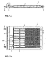
- Fig. 1 a is shown a side view of the electric heater 1 according to the invention.
- Fig. 1b shows a plan view of the electric heater 1.
- the electric heater 1 includes a heating block, which consists of a plurality of layered or stacked heating elements 2.
- Each heating element 2 consists of a resistance heating element and adjacent thereto arranged radiators or Winnipegleitblechen.
- resistance heating elements PTC elements are preferably used.
- the heating block from the heating elements 2 is held in a frame.
- This frame consists of opposite longitudinal beams 3 and perpendicularly arranged side rails 4 and 5.
- the bars of the frame are either metal or made of plastic.
- the two side rails 4 and 5 differ in the in Fig. 1 illustrated embodiment.
- the side rail 4 of the side rail 5 is formed as a box open on one side.
- the opening of this box-shaped side member 5 is located on the side opposite the heating elements 2 side rail 5.
- a control device can be used, which controls the heat output of the individual heating elements 2 by controlling the heating elements 2 supplied current.
- the open side of the formed as a box side rail 5 is closed after insertion of the control circuit with a clip-on or clip-on lid.
- the circuit board of the control device is preferably arranged perpendicular to the frame plane after insertion, but it is also a parallel arrangement possible (not shown).
- the heater 1 is powered by two connection pins 8 with power. They are designed so that they can easily conduct the required heating currents.
- the connecting bolts 8 project in the in Fig. 1 illustrated embodiment on the side on which the box-shaped side member 5 is open.
- the side rail 5 has window openings 7 on the sides lying in the surface plane of the frame. These window openings 7 are arranged so that they are also in the air stream to be heated. Between the opposite window openings 7 cooling elements 150 are arranged, which are associated with the power electronics components of the control circuit. During operation not only the heating block from the heating elements 2, but also the window openings of air to be heated is flowed through.
- the choice of the size of the window openings 7 allows to determine the proportion of the amount of air flowing past the cooling elements 150.
- the air flow rate is adjusted so that the air which has flowed through the heating block and the air which has flowed past the cooling elements 150 have the smallest possible temperature differences. Only when the air which has flowed through the window openings 7 comes as close as possible to the temperature of the air which has passed through the heating block, the highest possible efficiency is achieved in the operation of the heating device.
- FIG. 2 shows a detailed view of the arranged within the box-shaped side member control device.
- On a circuit board 110 in addition to power electronics components control electronics (not shown) is provided.
- the control electronics determines the amount of electricity to be delivered by the power electronics components, in particular the power transistors 119, to the respective heating element 2 associated therewith.
- the circuit board is equipped only on one side with components. According to the number of heating stages, the circuit board has horizontally mounted on this power transistors 119. In the exemplary embodiment shown, three heating stages and accordingly three power transistors are provided. Each power transistor 119 is soldered to the printed circuit board 110 at its output terminal.
- Each of the power transistors 119 is connected to a cooling element 150 for dissipating the heat loss.
- the cooling element contacts the transistor directly. Such contacting takes place according to the invention via an opening 140 arranged below the transistor.
- the cooling element 150 is designed as a pin-shaped body. To simplify manufacture, the shape of the cooling element is substantially cylindrical. Especially a board-side portion 151 is provided which is inserted into the circuit board and a portion 152 which protrudes perpendicularly from the circuit board 110 at the lower side.
- the circuit board side portion 151 is provided with a knurling which makes it possible to mechanically connect the cooling element to the circuit board.
- the attachment of the cooling element takes place in that the cooling element is pressed into the circuit board, so that the portion 151 forms a firm connection with the edge of the opening 140.
- the knurling provides a toothing of the portion 151 with the edge of the opening 140, so that immediately after pressing a resilient connection is achieved.
- the board-side portion 151 has a slightly conical shape. By this shaping the insertion of the cooling element is simplified in the circuit board.
- the protruding from the circuit board portion 152 of the cooling element has a slightly smaller diameter than the portion 151 which is pressed into the circuit board. This makes it possible to use the cooling element of the same side from which the placement of the board with electrical components, in the circuit board.
- a cooling element 161 inserted into the printed circuit board and a cooling element 162, on which a power transistor 119 is mounted are shown.
- the cooling elements are inserted into the circuit board so that the end face of its circuit board side portion 151 is flush with the surface of the circuit board 110.
- a power transistor is mounted above the cooling element at the intended location. This happens, for example, in that the power transistor is soldered to the transistor base and possibly to its laterally led out terminals to the circuit board.
- a metallized surface 141 may be provided around the edge of the bore, so that the power transistor is soldered to the cooling element and to the printed circuit board.
- a direct contacting of the power transistors 119 via a hole in the printed circuit board 110 is particularly advantageous for power transistors in SMD design. Due to their design, such transistors have no cooling vanes to which cooling elements can be fastened.
- the edge of the opening 140 can be metallized.
- the opening is coated in a galvanic process in a layer thickness of about 50 microns with copper.
- the cooling element is used with a press-in force of about 800 Newton. This creates a mechanical connection between the cooling element and the circuit board, which withstands heavy loads. In particular, this compound withstands the loads normally occurring in a motor vehicle over a long service life.
- the opening 140 has a diameter of 8.05 mm.
- the cooling element has a diameter of 8.3 mm at its upper side of the printed circuit board side.
- this section has a conical shape, according to which the peripheral surface is inclined at an angle of 6 ° to the longitudinal axis of the cooling element.
- the portion 152 which protrudes from the printed circuit board after insertion, has a diameter of 7.5 mm in this embodiment.
- the diameters of the opening and of the cooling element can be varied within a wide range.
- Useful diameters for the cooling element are between 4 and 11 mm.
- diameters between 6 and 9 mm are used.
- the length of the cooling element can be between 15 and 40 mm.
- a length of 20 and 30 mm is selected.
- the length is selected such that the section 152 projecting from the printed circuit board projects into an air flow which forms between opposite window openings 7. As a result, efficient transport takes place, the heat transferred to the cooling element.
- the shape of the cooling element is optimized especially with regard to the simple and efficient manufacturability. By appropriate dimensioning of the diameter and the length of the cooling element, however, a sufficient removal of the heat generated by the power transistors is achieved.
- the cooling element is made of either copper or aluminum. Copper is an excellent conductor of heat.
- a cooling element fabricated therefrom has a small temperature gradient between the end face where the heat is transferred from the power transistor and the portion 152 that dissipates the heat to the passing air flow. As a result, the heat generated by the power transistor is dissipated very efficiently. Due to the good thermal conductivity, it is possible to keep the length and the diameter of the cooling element low.
- An aluminum cooling element has good thermal conductivity. A manufactured therefrom cooling element needs compared to a copper cooling element a larger area to deliver the heat to the air flowing through. However, since aluminum has a much lower density than copper, the cooling member made of aluminum is lighter than a copper cooling member, so that the mechanical stress of the connection between the cooling element and the circuit board is lower. Furthermore, the material costs for aluminum are significantly lower than for copper.
- the underside of the power transistor connected to the cooling element is usually at positive potential. However, in order to increase the reliability of the electric heater, it is desirable to keep all externally accessible surfaces of the heater free of potential.
- An electrically insulating (but good heat-conducting) coating electrical insulation of the cooling elements 150 is achieved. Preferably, this coating is only in the places of Surface provided, which are accessible from the outside, which are for example in the window openings 7.
- An attachment of the power transistor 119 on the cooling element 150 carried out by soldering.
- soldering the power transistor to the cooling element it is also possible to glue the transistor by means of a good conductive adhesive on its underside with the circuit board 110 and the cooling element 150 inserted therein. This avoids the thermal stress that would be placed on the power transistor during soldering to the cooling element.
- the available choice of transistors is not limited by the requirements of high heat resistance.
- the bonding can be carried out, for example, following a soldering process in which the electronic components and the connection wires of the power transistor are connected to the printed circuit board.
- the bonding results in electrical insulation between the power transistor and the cooling element, so that the surface of the cooling element remains potential-free.
- An epoxy resin adhesive allows a particularly strong connection of both components. With a silicone adhesive different coefficients of expansion of the bonded materials can be compensated. Furthermore, an acrylic adhesive can be used. With all these adhesives, no plane-parallel surfaces of the cooling element and the underside of the power transistor are required because unevenness is compensated by the adhesive. This simplifies the production of the cooling element. In addition, the precision requirements for the insertion of the cooling element in the circuit board are lower.
- an electric heater with the pin-shaped cooling elements simplifies the production of the electric heater.
- the described cooling elements can be mounted in a single operation on the circuit board.
- the control circuit can be equipped in a short time and a simple production of the heater is achieved.
- the manufacturing costs for the heater are also lower because the manufacturing cost of the cooling element is low.
- With a corresponding dimensioning of the cooling elements a sufficient cooling effect of the power transistors, which control the electrical heating elements, guaranteed, however, compared to conventional heaters, the production cost of the heater according to the invention is lower.
- Fig. 3a shows a plan view of a cooling element 250 for use in the electric heater according to the invention, which has been optimized with respect to the previously described cooling element 150 in terms of heat dissipation.
- Fig. 3b shows a side view of this cooling element.
- the illustrated cooling element 250 has a circuit board side portion 251 which is used for mounting in the circuit board. This section is designed in the same way as the corresponding section 151 of the cooling element 150. Furthermore, the cooling element 250 has the sections 252 and 253, which protrude from the printed circuit board in the inserted state. In particular, the portion 253 is provided on its surface with radial projections or notches. These projections or indentations respectively cause turbulence of the air, which flows past the cooling element. As a result, a better release of heat to the passing air is achieved. Preferably, these notches or projections are provided only in a region which is located between the window openings 7. By such a shape, a better cooling effect is achieved without making the manufacture of the cooling element unnecessarily complicated.
- Fig. 4a, Fig. 4b and Fig. 4c shows a further embodiment of the electric heater according to the invention described so far.
- This embodiment particularly relates to the housing of the electric heater, in which the control device is used.
- Fig. 4a shows a side view of such an electric heater.
- Fig. 4b is a detail from the Fig. 4a shown enlarged.
- Fig. 4c represents a section along the line AA in plan view.
- a control circuit that is substantially the same as in FIG Fig. 2 corresponds to the control circuit shown used.
- the pin-shaped cooling elements 350 correspond to those in FIG Fig. 2 or the in Fig. 3a, 3b shown cooling elements.
- brackets 310 are provided according to this embodiment of the invention, the cooling elements 350 fix. Especially with longer cooling elements such a holder provides protection against mechanical stresses to which the heater is exposed during operation of a motor vehicle.
- the brackets 310 which hold the cooling elements at the portion protruding from the circuit board, cause the stress of the connection between the portion 151 of the cooling element inserted in the circuit board and the opening 140 in the circuit board to be reduced. As a result, the durability of this compound is significantly increased. Thus, a safer operation is ensured even for a long period of operation for the heater according to the invention.
- the holder is formed by a transverse strut of the housing, which has an opening or depression into which the portion of the cooling element projecting from the printed circuit board can be inserted.
- the ready-mounted control circuit can be easily inserted into a housing. At the same time a good mechanical fixation of the cooling elements is achieved.
- the housing is formed by longitudinal bars 3 and side rails 4 and 5 arranged perpendicular thereto.
- the side rail 5 is box-shaped to receive the control device. Therefore, the brackets are arranged in the box-shaped side spar 5.
- the present invention also includes embodiments in which the heating device are arranged together with the control device in a common plastic housing. Accordingly, in such a housing in the housing portion which receives the control device, corresponding brackets 310, for example formed by cross braces, provided to fix the cooling elements.
- the holder is preferably formed as a transverse rib, which is provided in the window openings 307 and 308, respectively.
- a transverse rib Such a structure of the housing affects the airflow flowing through the window openings only minimally.
- the length of the cooling element can be chosen so that the cooling element is flowed around at the highest possible proportion of its surface of air. In particular, it is not necessary to extend the cooling element beyond the window opening, so that the cooling element can engage with a holder possibly mounted below the window opening.
- the end face of the protruding from the circuit board portion of the cooling element 350 is used for heat dissipation.
- the transverse rib within the window opening simultaneously causes a stiffening of the housing in the region of the window openings.
- a window opening 308 may also be provided for every two or more cooling elements.
- the cross member or cross rib 310 is formed so that the opening in the cross member or cross rib 310, in which the cooling element is used, has a slightly smaller diameter than the cooling element. Furthermore, if at least the edge region of this opening has a certain elasticity, the cooling element is securely fixed after insertion into the holder 310.
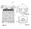
- Fig. 5a a side view of such a heater.
- Fig. 5b shows a detail in the region of a window opening of this heater.
- Fig. 5c shows a cross section along a line AA within the window opening in plan view.
- the cooling elements 450 and the control circuit essentially correspond to those in FIG Fig. 2 and Fig. 3a, 3b shown embodiments.
- the pin-shaped cooling element 450 is additionally provided with a cooling plate 420 in order to further increase the cooling effect.
- This cooling plate 420 is preferably mounted in the region of the window opening 408 on the pin-shaped cooling element 450.
- the heat sink can be easily adapted to the thermal and mechanical requirements that are placed on the respective heaters. This is done by selecting a suitable material, a surface structure and the shape of the cooling plate.
- a base cooling element namely the pin-shaped cooling element 450, can be adapted to different requirements in a simple manner.
- the cooling plate is preferably designed so that it can be clamped onto the cooling pin 450.
- the cooling plate 420 is preferably bent in ⁇ -shape.
- the cooling plate engages around the cooling pin 450 to enter into a clamping connection with this. Lateral portions of the cooling plate 420 protrude from the cooling pin to release the absorbed heat to the airflow passing through the window openings 408.
- copper or aluminum are preferably used.
- Aluminum is characterized by a good used around.
- Aluminum is characterized by good thermal conductivity and low material costs. Copper has excellent thermal conductivity.
- the material thickness is determined so as to ensure a reliable, tight clamping fit of the cooling element on the cooling pin 450.
- the projecting from the cooling pin 450 sections of the cooling plate 420 are designed in the form of cooling fingers or cooling fins to deliver the heat absorbed by the cooling pin as efficiently as possible to the passing air.
- a stop 460 is additionally provided for the cooling plate.
- the heat sink 420 can be glued to the stop 460 for attachment.
- the cooling plate serves in addition to increasing the cooling effect at the same time the purpose of additional fixation of the cooling pin. This also ensures safe operation of the heater over a long period of time.
- the cooling pin 450 may be fixed within the housing.
- a recess 410 is formed in a transverse strut of the housing, into which the cooling pin 450 is used for fixing.
- the present invention relates to an electric heater as auxiliary heater for motor vehicles, in which the heater and the control device are integrated into a structural unit.
- the heater and the control device are integrated into a structural unit.
- power transistors are provided for driving the heating elements of the heating register directly mounted on the circuit board.
- the cooling element is designed as a pin-shaped solid body.
- the Cooling element inserted into the respective opening and protrudes vertically from the bottom of the circuit board.
Landscapes
- Engineering & Computer Science (AREA)
- Microelectronics & Electronic Packaging (AREA)
- Cooling Or The Like Of Electrical Apparatus (AREA)
- Air-Conditioning For Vehicles (AREA)
Description
Die Erfindung bezieht sich auf eine elektrische Heizvorrichtung zur Lufterwärmung, die sich insbesondere für den Einsatz als elektrische Zusatzheizung in Kraftfahrzeugen eignet.The invention relates to an electric heater for air heating, which is particularly suitable for use as electric auxiliary heating in motor vehicles.
Für den Einsatz in Kraftfahrzeugen, insbesondere solchen mit verbrauchsoptimierten Motoren, werden elektrische Heizvorrichtungen zur Beheizung des Innenraums und/oder des Motors verwendet. Eine elektrische Zusatzheizung ist insbesondere nach dem Starten des Motors erforderlich, solange der Verbrennungsmotor noch keine ausreichende Wärmeenergie zur Verfügung stellt. Verbrauchsoptimierte Verbrennungsmotoren erfordern sogar grundsätzlich den Einsatz elektrischer Zusatzheizen.For use in motor vehicles, especially those with consumption-optimized engines, electric heaters are used for heating the interior and / or the engine. An additional electric heater is required in particular after starting the engine, as long as the engine does not provide sufficient heat energy available. Consumption-optimized combustion engines even require in principle the use of additional electrical heating.
Der Einsatz solcher Heizvorrichtungen ist jedoch nicht auf den Kraftfahrzeugbereich beschränkt, sie sind auch für eine Vielzahl anderer Einsatzzwecke geeignet, beispielsweise im Bereich von Hausinstallationen (Raumklimatisierung), Industrieanlagen und dergleichen.However, the use of such heaters is not limited to the automotive field, they are also suitable for a variety of other applications, such as in the field of domestic (air conditioning), industrial equipment and the like.
Aus
Die elektronischen Schalter, insbesondere in Form von Leistungstransistoren, die den Strom steuern, der den Heizelementen zugeführt wird, sind mit einer Seite direkt auf einer Leiterplatte montiert. Zur Abführung der von den Leistungstransistoren erzeugten Verlustwärme ist auf der gegenüberliegenden Seite der Leiterplatte ein Kühlelement oder -blech vorgesehen. Ein solches Kühlelement, das direkt den Leistungstransistor kontaktiert, kann die Verlustwärme des Leistungstransistors auf einfache Weise und in ausreichender Menge abführen.The electronic switches, in particular in the form of power transistors controlling the current supplied to the heating elements, are mounted with one side directly on a printed circuit board. To dissipate the heat loss generated by the power transistors, a cooling element or sheet is provided on the opposite side of the circuit board. Such a cooling element, which directly contacts the power transistor, can dissipate the heat loss of the power transistor in a simple manner and in sufficient quantity.
Als Kühlelement kommt ein U-förmig gestalteter Kühlkörper zum Einsatz mit Kühlrippen bzw. Fingern, die von einer Grundfläche abstehen. An der Unterseite des Kühlkörpers ist ein Zapfen vorgesehen, der in die Leiterplatte zur Kontaktierung des Leistungstransistors einsetzbar ist.As a cooling element is a U-shaped heat sink is used with cooling fins or fingers that protrude from a base. At the bottom of the heat sink, a pin is provided which can be inserted into the circuit board for contacting the power transistor.
Eine solche herkömmliche Anordnung ist jedoch aufwändig in der Herstellung, da insbesondere der Kühlkörper eine komplizierte Form aufweist. Nachteilig an dieser Heizvorrichtung ist des Weiteren die Klemmbefestigung des Kühlelementes an dem Transistor. Diese Befestigung erfordert im Anschluss an das Einsetzen des Kühlkörpers einen weiteren Arbeitsgang zur Befestigung einer Klammer, die den Kühlkörper hält. Zudem ist die Klemmung nicht in der Lage, Unebenheiten in der Anlagefläche von Transistor und der Oberfläche des durch die Leiterplatte ragenden Zapfenelementes auszugleichen. Dadurch wird der Wärmeübergang unkalkulierbar beeinträchtigt, und die Anlagefläche ist nicht in der Lage, die Verlustwärme vom Leistungstransistor über der gesamten Transistorfläche gleichmäßig abzuleiten.However, such a conventional arrangement is expensive to manufacture because in particular the heat sink has a complicated shape. A disadvantage of this heater is further the clamping attachment of the cooling element to the transistor. This attachment requires following the insertion of the heat sink, another operation for fixing a clip that holds the heat sink. In addition, the clamping is not able to compensate for unevenness in the contact surface of the transistor and the surface of the protruding through the circuit board pin member. As a result, the heat transfer is affected incalculable, and the contact surface is not able to dissipate the heat loss from the power transistor across the entire transistor surface uniformly.
Alternativ ist vorgesehen, das Kühlelement zweiteilig auszubilden. Dazu wird ein Wärmeleitelement in die Leiterplatte eingesetzt und mit dem der Transistor an der Anlagefläche verlötet. Auf das Wärmeleitelement wird ein Kühlkörper aufgeklebt. Dieser Kühlkörper ist z.B. L-förmig gestaltet mit einer Grundfläche und von dieser Grundfläche abstehenden Kühlrippen. Mit einer solchen Kühlelementanordnung kann die Klemmung entfallen und gleichzeitig kann ein zuverlässig hoher Wärmeübergangswert an der Anlagefläche von Transistor und der Oberfläche des durch die Leiterplatte ragenden Wärmeleitelements sichergestellt werden.Alternatively, it is provided to form the cooling element in two parts. For this purpose, a heat conducting element is inserted into the circuit board and soldered to the transistor at the contact surface. On the heat-conducting a heat sink is glued. This heat sink is e.g. L-shaped design with a base and protruding from this base cooling fins. With such a cooling element arrangement, the clamping can be omitted and at the same time a reliably high heat transfer value can be ensured at the contact surface of the transistor and the surface of the heat conducting element projecting through the printed circuit board.
Nachteilig an einer solchen Befestigung ist die aufwändige Herstellung. Insbesondere ist es notwendig, für jedes Kühlelement den Kühlkörper und das Wärmeleitelement separat herzustellen. Zusätzlich fallen bei der Fertigung der Steuerschaltung mehrere Arbeitsgänge an, um das Wärmeleitelement in die Leiterplatte einzusetzen und den Kühlkörper an dem Wärmeleitelement zu befestigen.A disadvantage of such a fixture is the complex production. In particular, it is necessary to produce the heat sink and the heat conducting element separately for each cooling element. In addition, several operations are involved in the manufacture of the control circuit in order to use the heat conducting element in the circuit board and to attach the heat sink to the heat conducting element.
Zur Vereinfachung der Befestigung des Kühlkörpers ist außerdem vorgeschlagen, den Kühlkörper mit Hilfe des Wärmeleitelements an der Leiterplatte zu befestigen. Dazu ist das Wärmeleitelement an dem aus der Leiterplatte herausragenden Ende mit einem seitlich vorspringenden Abschnitt versehen. In der Grundfläche des Kühlkörpers ist eine entsprechende Öffnung vorgesehen, durch die das Wärmeleitelement durch die Leiterplatte ragt. Der seitliche Vorsprung des Wärmeleitelements fixiert den Kühlkörper an der Leiterplatte.To simplify the attachment of the heat sink is also proposed to attach the heat sink with the aid of the heat conducting element to the circuit board. For this purpose, the heat-conducting element is provided on the projecting from the circuit board end with a laterally projecting portion. In the base of the heat sink, a corresponding opening is provided, through which the heat-conducting element projects through the printed circuit board. The lateral projection of the heat-conducting element fixes the heat sink to the printed circuit board.
Diese Bauform eines Kühlelementes erfordert jedoch immer noch die Bereitstellung von mehreren Bauteilen für ein Kühlelement. Des Weiteren ist es nötig, den Kühlkörper zunächst auf die Leiterplatte aufzusetzen und vorläufig zu fixieren, bis das Wärmeleitelement eingesetzt und befestigt ist. Dadurch bleibt die Herstellung der elektrischen Heizvorrichtung zeitaufwändig und kompliziert.However, this design of a cooling element still requires the provision of multiple components for a cooling element. Furthermore, it is necessary to first set up the heat sink on the circuit board and provisionally fix until the heat-conducting element is inserted and fixed. As a result, the production of the electric heater remains time-consuming and complicated.
Aus der Druckschrift
Problematisch an dieser Anordnung ist jedoch die mechanischen Stabilität, insbesondere der Verbindung zwischen Bauelement und Kühlkörper, um einen guten Wärmeübergang sicherzustellen. Dieses Problem besteht vor allem bei großen Kühlkörpern, wie sie zur Abführung hoher Verlustleistungen erforderlich sind.The problem with this arrangement, however, is the mechanical stability, in particular the connection between the component and the heat sink, in order to ensure a good heat transfer. This problem exists especially with large heat sinks, as they are required to dissipate high power losses.
Aufgabe der Erfindung ist es daher, eine einfache herzustellende Heizvorrichtung mit ausreichender Abfuhr der Verlustwärme anzugeben.The object of the invention is therefore to provide a simple heater to be produced with sufficient dissipation of the heat loss.
Diese Aufgabe wird mit den Merkmalen des Patentanspruchs 1 gelöst.This object is achieved with the features of
Erfindungsgemäß ist das Kühlelement als stiftförmiger Vollkörper ausgebildet, der zur Anbindung an den Leistungstransistor in eine Öffnung in der Leiterplatte eingesetzt ist. Die Abgabe der an die Kühlelemente übertragenen Wärme erfolgt auf besonders effiziente Weise dadurch, dass das Kühlelement über in einem Gehäuse der Heizvorrichtung vorgesehene Fensteröffnungen von der zu erwärmenden Luft umströmbar ist. Dazu ragt das Kühlelement entsprechend weit aus der Leiterplatte heraus. Durch das Vorsehen von Fensteröffnungen kann der zur Kühlung der Leistungselektronik verwendete Luftdurchsatz gesteuert werden. Vorzugsweise sind die Fensteröffnungen so angeordnet, dass allein die Kühlelemente von Außenluft umströmbar sind. Auf diese Weise ist die zur Kühlung der Leistungselektronik verwendete Luftmenge so einstellbar, dass keine Zonen unterschiedlicher Temperatur im erwärmten Luftstrom auftreten, so dass insbesondere der Kühlluftstrom und der von den Radiatorelementen aufgeheizte Luftstrom in etwa dieselbe Ausgangstemperatur aufweisen. Auf diese Weise wird die Effektivität der gesamten HeizvorrichtungAccording to the invention the cooling element is designed as a pin-shaped solid body, which is used for connection to the power transistor in an opening in the circuit board. The delivery of the heat transferred to the cooling elements takes place in a particularly efficient manner in that the cooling element can be flowed around by the air to be heated via window openings provided in a housing of the heating device. For this purpose, the cooling element protrudes correspondingly far out of the circuit board. By providing window openings, the air flow used to cool the power electronics can be controlled. Preferably, the window openings are arranged so that only the cooling elements can be flowed around by outside air. In this way, the amount of air used for cooling the power electronics is adjustable so that no zones of different temperature occur in the heated air flow, so that in particular the cooling air flow and the air flow heated by the radiator elements have approximately the same starting temperature. In this way, the effectiveness of the entire heater
nicht durch den zur Kühlung der Steuerelektronik abgezweigten Luftstrom vermindert.not reduced by the branched off to cool the control electronics airflow.
Erfindungsgemäß ist in dem Gehäuse eine Halterung zur Fixierung des aus der Leiterplatte herausragenden Abschnitt des Kühlelementes vorgesehen. Durch eine solche Halterung ist ein Schutz der Kühlelemente gegen mechanische Belastungen gewährleistet. So kann sichergestellt werden, dass auch nach langer Betriebsdauer die feste Verbindung zwischen der Leiterplatte und den Kühlelementen gewährleistet ist. Des Weiteren wird es möglich, größere und damit schwerere Kühlelemente einzusetzen, um somit eine höhere Kühlwirkung zu erzielen.According to the invention, a holder for fixing the protruding from the circuit board portion of the cooling element is provided in the housing. By such a holder, a protection of the cooling elements is guaranteed against mechanical stress. So it can be ensured that even after a long period of operation, the firm connection between the circuit board and the cooling elements is guaranteed. Furthermore, it is possible to use larger and therefore heavier cooling elements, so as to achieve a higher cooling effect.
In bevorzugter Weise wird die Halterung durch eine Querstrebe des Gehäuses gebildet ist, die eine Öffnung oder Vertiefung aufweist, in die das Kühlelement hineinragt. In diese Öffnung oder Vertiefung lassen sich die schon an der Leiterplatte befestigten Kühlelemente einfach einsetzten. Damit vereinfacht sich der Einbau der Steuerschaltung in die Heizvorrichtung.Preferably, the holder is formed by a transverse strut of the housing, which has an opening or depression into which projects the cooling element. In this opening or depression, the already attached to the circuit board cooling elements can be used easily. This simplifies the installation of the control circuit in the heater.
Vorzugsweise ist die Halterung als eine zwischen sich gegenüberliegenden Fensteröffnungen angeordnete Querrippe ausgebildet. Dieser Aufbau ermöglicht eine mechanische Fixierung des Kühlelementes innerhalb der Fensteröffnungen, wobei der durch die Fensteröffnungen strömende Luftstrom nur minimal beeinträchtigt wird. Dementsprechend kann die Länge des Kühlelements so gewählt werden, dass das Kühlelement an einem möglichst hohen Flächenanteil von Luft umströmt wird. Insbesondere ist es nicht nötig einen zusätzlichen Befestigungsabschnitt am Kühlelement vorzusehen. Zudem bewirkt die Querrippe gleichzeitig eine Versteifung des Gehäuses im Bereich der Fensteröffnungen.Preferably, the holder is designed as a transverse rib arranged between opposite window openings. This structure allows a mechanical fixation of the cooling element within the window openings, wherein the air flow flowing through the window openings is minimally affected. Accordingly, the length of the cooling element can be selected so that the cooling element is flowed around at the highest possible surface portion of air. In particular, it is not necessary to provide an additional attachment portion on the cooling element. In addition, the transverse rib simultaneously causes a stiffening of the housing in the region of the window openings.
Durch die besondere Form lässt sich ein solches Kühlelement zum Einen auf einfache Weise herstellen. Deshalb sind die Herstellungskosten für das Kühlelement niedrig. Außerdem können die Kühlelemente in einem einzigen Arbeitsgang an der Leiterplatte montiert werden, so dass sich die Fertigung der Heizvorrichtung vereinfacht,Due to the special shape, such a cooling element can be produced on the one hand in a simple manner. Therefore, the manufacturing cost of the cooling element is low. In addition, the cooling elements can be mounted in a single operation on the circuit board, so that simplifies the manufacture of the heater,
insbesondere kann die Steuerschaltung in kürzerer Zeit bestückt werden. Zum Anderen ist die Kühlwirkung eines solchen Kühlelementes bei entsprechender Dimensionierung ausreichend gewährleistet.In particular, the control circuit can be populated in a shorter time. On the other hand, the cooling effect of such a cooling element is adequately ensured with appropriate dimensioning.
Gemäß einer vorteilhaften Ausgestaltung der Erfindung weist das Kühlelement eine im Wesentlichen zylindrische Form auf. Eine solche Formgebung ermöglicht die weitere Senkung der Herstellungskosten.According to an advantageous embodiment of the invention, the cooling element has a substantially cylindrical shape. Such a design allows the further reduction of manufacturing costs.
Vorzugsweise ist der aus der Leiterplatte herausragende Abschnitt des Kühlelements mit radialen Vorsprüngen oder Einkerbungen versehen. Diese Vorsprünge bzw. Einkerbungen bewirken eine Verwirbelung der am Kühlelement vorbeigeführten Luft, so dass eine effizientere Wärmeabfuhr erzielt wird.Preferably, the protruding from the circuit board portion of the cooling element is provided with radial projections or notches. These projections or indentations cause a swirling of the air guided past the cooling element, so that a more efficient heat dissipation is achieved.
Das Kühlelement ist vorzugsweise mit seinem leiterplattenseitigen Abschnitt in die Öffnung eingepresst. Durch diese Befestigungsart verringert sich die für die Herstellung der Heizvorrichtung erforderlichen Arbeitsschritte. Insbesondere wird gleichzeitig mit dem Einsetzen des Kühlelements in die Leiterplatte eine belastbare Befestigung des Kühlelements an der Leiterplatte in einem einzigen Arbeitsgang hergestellt.The cooling element is preferably pressed with its printed circuit board side portion in the opening. By this type of attachment reduces the necessary steps for the production of the heater work steps. In particular, simultaneously with the insertion of the cooling element into the printed circuit board, a resilient attachment of the cooling element to the printed circuit board is produced in a single operation.
Gemäß einer vorteilhaften Ausgestaltung der Erfindung ist der leiterplattenseitigen Abschnitt des Kühlelements mit einer Rändelung versehen, die sich beim Einpressen mit der Leiterplatte verzahnt. Eine solche Ausgestaltung ermöglicht ein leichtes Einsetzen und gleichzeitig eine mechanische Fixierung. Auf diese Weise ist das Kühlelements nach dem Einsetzen sofort in der Leiterplatte mechanisch fixiert.According to an advantageous embodiment of the invention, the circuit board side portion of the cooling element is provided with a knurling, which meshes with the printed circuit board during pressing. Such a design allows easy insertion and at the same time a mechanical fixation. In this way, the cooling element is mechanically fixed immediately after insertion in the circuit board.
Vorzugsweise hat der leiterplattenseitige Abschnitt des Kühlelements einen größeren Umfang als der aus der Leiterplatte herausragende Abschnitt des Kühlelements. Durch diese Formgebung ist das Kühlelement von der gleichen Seite in die Leiterplatte einsetzbar von der aus auch die Bestückung der Leiterplatte mit elektronischen Komponenten wie beispielsweise den Leistungstransistoren, erfolgt. Somit vereinfacht sich die Herstellung der Steuerschaltung.Preferably, the circuit board side portion of the cooling element has a larger circumference than the protruding from the circuit board portion of the cooling element. As a result of this shaping, the cooling element can be inserted from the same side into the printed circuit board from which also the assembly of the printed circuit board with electronic components such as the power transistors takes place. Thus, the production of the control circuit simplifies.
Wenn zusätzlich der leiterplattenseitige Abschnitt eine konische Form aufweist, die sich in Richtung des aus der Leiterplatte herausragenden Abschnitts verjüngt, ist das Kühlelement durch den auf diesem befestigten Leistungstransistor gegen ein Herausfallen gesichert.In addition, if the board-side portion has a conical shape tapering toward the portion protruding from the circuit board, the cooling element is prevented from falling out by the power transistor mounted thereon.
Gemäß einer bevorzugten Ausgestaltung der Erfindung ist das Kühlelement aus Kupfer oder Aluminium gefertigt. Ein aus Kupfer bestehendes Kühlelement zeichnet sich durch eine hohe Wärmeleitfähigkeit aus. Dadurch tritt ein nur sehr geringer Temperaturgradient zwischen dem Leistungstransistor und der Oberfläche des Kühlelements auf, so dass die im Leistungstransistor erzeugte Wärme besonders effizient an die umgebende Luft abgegeben wird. Ein aus Aluminium gefertigtes Kühlelement hat eine gute Wärmeleitfähigkeit und zeichnet sich durch günstigere Materialkosten sowie eine geringere Masse aus.According to a preferred embodiment of the invention, the cooling element is made of copper or aluminum. A cooling element made of copper is characterized by a high thermal conductivity. As a result, only a very small temperature gradient occurs between the power transistor and the surface of the cooling element, so that the heat generated in the power transistor is emitted to the surrounding air in a particularly efficient manner. A made of aluminum cooling element has a good thermal conductivity and is characterized by lower material costs and a lower mass.
Die Leiterplatte ist vorzugsweise in einem Bereich um den Rand der Öffnung mit Kupfer beschichtet. Dadurch wird eine besonders belastbare Befestigung des Kühlelements an der Leiterplatte erzielt.The printed circuit board is preferably coated with copper in a region around the edge of the opening. As a result, a particularly resilient attachment of the cooling element is achieved on the circuit board.
Gemäß einer vorteilhaften Ausgestaltung weist das Kühlelement einen kreisförmigen Querschnitt mit einem Durchmesser zwischen 4 und 11 mm auf. Vorzugsweise beträgt der Durchmesser zwischen 6 und 9 mm. Die Länge des Kühlelements beträgt vorzugsweise zwischen 15 und 40 mm. Besonders bevorzugt wird eine Länge zwischen 20 und 30 mm. Derart dimensionierte Kühlelemente führen die in den Leistungstransistoren erzeugte Wärme in ausreichender Weise ab. Zudem ist das Gewicht der Kühlelemente niedrig, so dass die Leiterplatte und die Verbindung zwischen Kühlelement und Leiterplatte nicht unnötig belastet wird.According to an advantageous embodiment, the cooling element has a circular cross section with a diameter between 4 and 11 mm. Preferably, the diameter is between 6 and 9 mm. The length of the cooling element is preferably between 15 and 40 mm. Particularly preferred is a length between 20 and 30 mm. Such sized cooling elements perform the heat generated in the power transistors in a sufficient manner. In addition, the weight of the cooling elements is low, so that the circuit board and the connection between the cooling element and circuit board is not unnecessarily burdened.
Gemäß einer vorteilhaften Ausgestaltung der Erfindung ist ein Kühlblech an dem Kühlelement befestigt. Durch ein solches Kühlblech kann die Kühlwirkung weiter erhöht werden. Vorzugsweise ist das Kühlblech an die thermischen und mechanischen Bedingungen, die die jeweilige Heizung kennzeichnen, durch geeignete Auswahl des Materials, der Oberfläche und der Form angepasst. Somit erhält man auf einfache Weise ein optimal angepasstes Kühlelement ohne das Grundelement, den stiftförmigen Körper, anzupassen.According to an advantageous embodiment of the invention, a cooling plate is attached to the cooling element. By such a cooling plate, the cooling effect can be further increased. Preferably, the heat sink is adapted to the thermal and mechanical conditions that characterize the particular heater by appropriate choice of material, surface, and shape. Thus, one easily obtains an optimally adapted cooling element without the basic element, the pin-shaped body to adapt.
Vorzugsweise ist das Kühlblech zur Befestigung an dem Kühlelement auf das Kühlelement aufgeklemmt. Auf diese Weise wird ein zweiteiliges Kühlelement realisiert, bei dem das Kühlblech sicher an dem stiftförmigen Kühlkörper befestigt ist. Das Aufklemmen erfolgt in einem einfachen effizienten Arbeitsschritt, der keine Wartezeit, wie sie z.B. für das Aushärten eines Klebers erforderlich wäre, bedingt.Preferably, the cooling plate is clamped for attachment to the cooling element on the cooling element. In this way, a two-part cooling element is realized, in which the cooling plate is securely fastened to the pin-shaped heat sink. The clamping is done in a simple efficient operation that does not require a waiting time, as it would be required for the curing of an adhesive, for example.
Das Kühlblech ist vorzugsweise aus Aluminium oder Kupfer gefertigt. Beides sind Materialien mit hoher Wärmeleitfähigkeit, die sich zudem gut verarbeiten lassen.The cooling plate is preferably made of aluminum or copper. Both are materials with high thermal conductivity, which can also be processed well.
Zur besseren mechanischen Fixierung des Kühlelements ist das Kühlblech vorzugsweise an einem Gehäuse der Heizvorrichtung befestigt. In einer solchen Anordnung dient das Kühlblech neben der Erhöhung der Kühlwirkung zugleich dem Zweck der zusätzlichen mechanischen Befestigung des Kühlelementes. Dadurch kann auf effiziente Weise ein sicherer Betrieb der Heizung über eine lange Zeitdauer gewährleistet werden.For better mechanical fixation of the cooling element, the cooling plate is preferably fastened to a housing of the heating device. In such an arrangement, the cooling plate serves in addition to increasing the cooling effect at the same time the purpose of additional mechanical attachment of the cooling element. Thereby, safe operation of the heater for a long period of time can be ensured efficiently.
Um einen guten Wärmeübergangswert zwischen dem Leistungstransistor und dem Kühlkörper zu erzielen, ist der Leistungstransistor vorzugsweise mit dem jeweiligen in die Öffnungen der Leiterplatte eingesetzten Kühlelement verlötet.In order to achieve a good heat transfer value between the power transistor and the heat sink, the power transistor is preferably soldered to the respective cooling element inserted into the openings of the circuit board.
Gemäß einer weiteren bevorzugten Ausgestaltung der Erfindung ist der Leistungstransistor mit dem jeweiligen in die Öffnungen der Leiterplatte eingesetzten Kühlelement verklebt. Dadurch wird die thermische Belastung, die der Leistungstransistor während eines Verlötens mit dem Kühlelement ausgesetzt wäre, vermieden. Vorzugsweise wird die Unterseite des Leistungstransistor erst nach der Durchführung eines Lötprozesses auf die Öffnung aufgebracht und mit dem Kühlelement verklebt.According to a further preferred embodiment of the invention, the power transistor is glued to the respective cooling element inserted into the openings of the printed circuit board. This avoids the thermal stress that would be placed on the power transistor during soldering to the cooling element. Preferably, the underside of the power transistor is applied to the opening only after the implementation of a soldering process and bonded to the cooling element.
Bei einer Verklebung können verschiedene Kleber vorteilhaft verwendet werden. Ein Epoxidharzkleber ermöglicht eine besonders feste Verbindung beider Komponenten, insbesondere auch dann, wenn das Kühlelement zusätzlich mit der Leiterplatte verklebt wird. Ein Silikonkleber kann unterschiedliche Ausdehnungskoeffizienten der verklebten Materialien ausgleichen. Ein weiterer vorteilhaft einsetzbarer Kleber ist ein Acrylkleber. Der Vorteil dieser Kleber liegt insbesondere darin, dass keine planparallelen Flächen der Einzelteile, des Kühlelementes und des Leistungstransistors, erforderlich sind, da Unebenheiten durch die Kleber ausgeglichen werden.When gluing various adhesives can be used advantageously. An epoxy resin adhesive allows a particularly firm connection of both components, in particular even if the cooling element is additionally glued to the circuit board. A silicone adhesive can compensate for different coefficients of expansion of the bonded materials. Another advantageous adhesive is an acrylic adhesive. The advantage of this adhesive lies in the fact that no plane-parallel Surfaces of the items, the cooling element and the power transistor, are required because bumps are compensated by the adhesive.
Um die Gefahr, die von einem auf elektrischen Potential liegenden Kühlelement mit seinen von außen zugänglichen Oberflächen ausgeht, zu beseitigen, ist die Oberfläche des Kühlelementes auf der Außenseite mit einer elektrisch isolierenden Beschichtung versehen. Mit einer solchen Maßnahme kann auf einfache Weise ein elektrischer Kurzschluss, beispielsweise durch in den zu erwärmenden/erwärmten Luftstrom fallende Metallteile, verhindert werden.In order to eliminate the danger emanating from a lying at electrical potential cooling element with its externally accessible surfaces, the surface of the cooling element is provided on the outside with an electrically insulating coating. With such a measure, an electrical short circuit, for example by falling into the heated / heated air flow metal parts, can be prevented in a simple manner.
Vorzugsweise ist das Kühlelement nur in den Bereichen mit einer elektrisch isolierenden Schicht versehen, die von außen zugänglich sind, insbesondere also auf dem zwischen die Fensteröffnungen ragenden Abschnitt.Preferably, the cooling element is provided only in the areas with an electrically insulating layer, which are accessible from the outside, in particular so on the projecting portion between the window openings.
Weitere vorteilhafte Ausgestaltungen der Erfindung sind in den Unteransprüchen angegeben.Further advantageous embodiments of the invention are specified in the subclaims.
Im folgenden wird die Erfindung anhand der beiliegenden Zeichnungen beschrieben, in denen:
- Fig. 1 a und 1 b
- eine Aufsicht bzw. Seitenansicht einer erfindungsgemäßen elektrischen Heizvorrichtung zeigen,
- Fig. 2
- eine Detailansicht der mit Bauelementen und Kühlelementen bestückten Leiterplatte der Steuervorrichtung der erfindungsgemäßen Heizvorrichtung zeigt,
- Fig. 3a und 3b
- eine Aufsicht bzw. Seitenansicht einer erfindungsgemäßen Ausführungsform eines Kühlelements zeigen,
- Fig. 4a
- eine Seitenansicht einer weiteren Ausführungsform einer erfindungsgemäßen elektrischen Heizvorrichtung zeigt, bei der innerhalb von Fensteröffnungen Querrippen zur Befestigung der Kühlelemente vorgesehen sind,
- Fig. 4b
- eine Detailansicht im Bereich einer Fensteröffnung dieser Heizvorrichtung zeigt,
- Fig. 4c
- einen Schnitt entlang der Linie A-A innerhalb dieser Detailansicht zeigt,
- Fig. 5a
- eine Seitenansicht einer weiterer Ausführungsform einer erfindungsgemäßen elektrischen Heizvorrichtung zeigt, bei der zusätzliche Kühlbleche auf den Kühlelementen montiert sind,
- Fig. 5b
- eine Detailansicht im Bereich einer Fensteröffnung dieser Heizvorrichtung zeigt und
- Fig. 5c
- einen Schnitt entlang der Linie A-A innerhalb dieser Detailansicht zeigt.
- Fig. 1 a and 1 b
- show a plan or side view of an electric heater according to the invention,
- Fig. 2
- a detailed view of the equipped with components and cooling elements circuit board of the control device of the heating device according to the invention,
- Fig. 3a and 3b
- show a plan view and side view of an embodiment of a cooling element according to the invention,
- Fig. 4a
- shows a side view of a further embodiment of an electric heating device according to the invention, in which transverse ribs are provided for fastening the cooling elements within window openings,
- Fig. 4b
- shows a detailed view in the region of a window opening of this heating device,
- Fig. 4c
- shows a section along the line AA within this detail view,
- Fig. 5a
- 3 shows a side view of a further embodiment of an electrical heating device according to the invention, in which additional cooling plates are mounted on the cooling elements,
- Fig. 5b
- a detail view in the region of a window opening of this heater shows and
- Fig. 5c
- a section along the line AA within this detail view shows.
In
Während die Längsholme 3 im wesentlichen symmetrisch aufgebaut sind, unterscheiden sich die beiden Seitenholme 4 und 5 in der in
Die Leiterplatte der Steuervorrichtung ist nach dem Einsetzen vorzugsweise senkrecht zur Rahmenebene angeordnet, es ist jedoch auch eine parallele Anordnung möglich (nicht dargestellt).The circuit board of the control device is preferably arranged perpendicular to the frame plane after insertion, but it is also a parallel arrangement possible (not shown).
Die Heizvorrichtung 1 wird über zwei Anschlussbolzen 8 mit Strom versorgt. Sie sind so ausgebildet, dass sie problemlos die geforderten Heizströme leiten können. Die Anschlussbolzen 8 ragen in der in
Auf derselben Seite ist ein weiterer Steckersockel zur Ansteuerung der Steuervorrichtung vorgesehen, der in
Der Seitenholm 5 weist auf den Seiten, die in der Flächenebene des Rahmens liegen, Fensteröffnungen 7 auf. Diese Fensteröffnungen 7 sind so angeordnet, dass sie ebenfalls in dem zu erwärmenden Luftstrom liegen. Zwischen den sich gegenüberliegenden Fensteröffnungen 7 sind Kühlelemente 150 angeordnet, die den Leistungselektronikbauelementen der Steuerschaltung zugeordnet sind. Beim Betrieb wird nicht nur der Heizblock aus den Heizelementen 2, sondern ebenfalls die Fensteröffnungen von zu erwärmender Luft durchströmt.The
Die Wahl der Größe der Fensteröffnungen 7 erlaubt, den Anteil der Luftmenge zu bestimmen, die an den Kühlelementen 150 vorbeiströmt. Erfindungsgemäß wird der Luftdurchsatz so eingestellt, dass die durch den Heizblock geströmte Luft und die an den Kühlelementen 150 vorbeigeströmte Luft möglichst geringe Temperaturunterschiede aufweisen. Nur wenn die durch die Fensteröffnungen 7 geströmte Luft in ihrer Temperatur der durch den Heizblock geströmten Luft möglichst nahe kommt, wird eine möglichst hohe Effizienz beim Betrieb der Heizvorrichtung erreicht.The choice of the size of the window openings 7 allows to determine the proportion of the amount of air flowing past the
Die Leiterplatte ist nur einseitig mit Bauelementen bestückt. Entsprechend der Anzahl von Heizstufen weist die Leiterplatte waagerecht auf dieser befestigte Leistungstransistoren 119 auf. Im gezeigten Ausführungsbeispiel sind drei Heizstufen und dementsprechend drei Leistungstransistoren vorgesehen. Jeder Leistungstransistor 119 ist an seinem Ausgangsanschluss fest mit der Leiterplatte 110 verlötet.The circuit board is equipped only on one side with components. According to the number of heating stages, the circuit board has horizontally mounted on this
Jeder der Leistungstransistoren 119 ist zur Abführung der Verlustwärme mit einem Kühlelement 150 verbunden. Zur Abführung der Wärme vom Transistor zum Kühlelement kontaktiert das Kühlelement den Transistor direkt. Eine solche Kontaktierung erfolgt erfindungsgemäß über eine unter dem Transistor angeordnete Öffnung 140.Each of the
Das Kühlelement 150 ist als stiftförmiger Körper ausgebildet. Um die Herstellung zu vereinfachen ist die Form des Kühlelementes im Wesentlichen zylindrisch. Insbesondere ist ein leiterplattenseitiger Abschnitt 151 vorgesehen, der in die Leiterplatte eingesetzt wird und ein Abschnitt 152, der aus der Leiterplatte 110 an der unteren Seite senkrecht herausragt.The
Der leiterplattenseitige Abschnitt 151 ist mit einer Rändelung versehen, die es ermöglicht, das Kühlelement mit der Leiterplatte mechanisch zu verbinden. Erfindungsgemäß erfolgt die Befestigung des Kühlelements dadurch, dass das Kühlelement in die Leiterplatte eingepresst wird, so dass der Abschnitt 151 eine feste Verbindung mit dem Rand der Öffnung 140 eingeht. Die Rändelung sorgt für eine Verzahnung des Abschnitts 151 mit dem Rand der Öffnung 140, so dass sofort nach dem Einpressen eine belastbare Verbindung erreicht wird. In der gezeigten Ausführungsform weist der leiterplattenseitige Abschnitt 151 eine leicht konische Form auf. Durch diese Formgebung wird das Einsetzen des Kühlelements in die Leiterplatte vereinfacht.The circuit
Der aus der Leiterplatte herausragende Abschnitt 152 des Kühlelements hat einen geringfügig geringeren Durchmesser als der Abschnitt 151, der in die Leiterplatte eingepresst wird. Dadurch ist es möglich, das Kühlelement von der gleichen Seite, von der aus die Bestückung der Platine mit elektrischen Bauelementen erfolgt, in die Leiterplatte einzusetzen.The protruding from the
In
Eine direkte Kontaktierung der Leistungstransistoren 119 über eine Bohrung in der Leiterplatte 110 ist insbesondere für Leistungstransistoren in SMD-Ausführung vorteilhaft. Solche Transistoren weisen bauartbedingt keine Kühlfahnen auf, an denen Kühlelemente befestigbar sind.A direct contacting of the
Um die Festigkeit der Verbindung zwischen dem Kühlelement und der Öffnung 140 in der Leiterplatte zu erhöhen, kann zusätzlich der Rand der Öffnung 140 metallisiert werden. Vorzugsweise wird die Öffnung in einem galvanischen Verfahren in einer Schichtstärke von ca. 50 µm mit Kupfer beschichtet. In die beschichtete Öffnung wird das Kühlelement mit einer Einpresskraft von etwa 800 Newton eingesetzt. Dadurch entsteht eine mechanische Verbindung zwischen dem Kühlelement und der Leiterplatte, die starken Belastungen standhält. Insbesondere hält diese Verbindung den in einem Kraftfahrzeug üblicherweise auftretenden Belastungen über eine lange Betriebsdauer stand.In order to increase the strength of the connection between the cooling element and the
In der gezeigten Ausführungsform hat die Öffnung 140 einen Durchmesser von 8,05 mm. Das Kühlelement hat an seinem oberen leiterplattenseitigen Abschnitt einen Durchmesser von 8,3 mm. Zudem weist dieser Abschnitt eine konische Form auf, derzufolge die Umfangsfläche mit einem Winkel von 6° gegen die Längsachse des Kühlelements geneigt ist. Der Abschnitt 152, der nach dem Einsetzen aus der Leiterplatte herausragt, hat in dieser Ausführungsform einen Durchmesser von 7,5 mm.In the embodiment shown, the
Erfindungsgemäß können die Durchmesser der Öffnung und des Kühlelements in einem weiten Bereich variiert werden. Sinnvolle Durchmesser für das Kühlelement liegen zwischen 4 und 11 mm. Vorzugsweise werden Durchmesser zwischen 6 und 9 mm verwendet. Die Länge des Kühlelements kann zwischen 15 und 40 mm betragen. Vorzugsweise wird eine Länge von 20 und 30 mm gewählt. Insbesondere ist die Länge so gewählt, dass der aus der Leiterplatte vorstehende Abschnitt 152 in einen Luftstrom, der sich zwischen gegenüberliegenden Fensteröffnungen 7 ausbildet, hineinragt. Dadurch erfolgt ein effizienter Transport, der an das Kühlelement übertragenen Wärme.According to the invention, the diameters of the opening and of the cooling element can be varied within a wide range. Useful diameters for the cooling element are between 4 and 11 mm. Preferably, diameters between 6 and 9 mm are used. The length of the cooling element can be between 15 and 40 mm. Preferably, a length of 20 and 30 mm is selected. In particular, the length is selected such that the
Die Form des Kühlelements ist besonders im Hinblick auf die einfache und effiziente Herstellbarkeit hin optimiert. Durch eine entsprechende Dimensionierung des Durchmessers sowie der Länge des Kühlelements wird jedoch ein ausreichender Abtransport der durch die Leistungstransistoren erzeugten Wärme erreicht.The shape of the cooling element is optimized especially with regard to the simple and efficient manufacturability. By appropriate dimensioning of the diameter and the length of the cooling element, however, a sufficient removal of the heat generated by the power transistors is achieved.
Um eine möglichst gute Kühlwirkung zu erzielen, ist das Kühlelement entweder aus Kupfer oder Aluminium gefertigt. Kupfer ist ein hervorragender Wärmeleiter. Ein daraus gefertigtes Kühlelement weist einen geringen Temperaturgradienten zwischen der Stirnseite, an der die Wärme vom Leistungstransistor übertragen wird, und dem Abschnitt 152, der die Wärme an den vorbeiströmenden Luftstrom abgibt, auf. Dadurch wird die vom Leistungstransistor erzeugte Wärme sehr effizient abgeführt. Durch die gute Wärmeleitfähigkeit ist es möglich, die Länge und den Durchmesser des Kühlelements gering zu halten.In order to achieve the best possible cooling effect, the cooling element is made of either copper or aluminum. Copper is an excellent conductor of heat. A cooling element fabricated therefrom has a small temperature gradient between the end face where the heat is transferred from the power transistor and the
Ein Kühlelement aus Aluminium weist eine gute Wärmeleitfähigkeit auf. Ein daraus gefertigtes Kühlelement benötigt im Vergleich zu einem Kupferkühlelement eine größere Fläche, um die Wärme an die durchströmende Luft abzugeben. Da Aluminium jedoch eine wesentlich geringere Dichte als Kupfer hat, ist das aus Aluminium gefertigte Kühlelement leichter als ein Kupferkühlelement, so dass die mechanische Belastung der Verbindung zwischen dem Kühlelement und der Leiterplatte geringer ist. Des Weiteren sind die Materialkosten für Aluminium deutlich niedriger als für Kupfer.An aluminum cooling element has good thermal conductivity. A manufactured therefrom cooling element needs compared to a copper cooling element a larger area to deliver the heat to the air flowing through. However, since aluminum has a much lower density than copper, the cooling member made of aluminum is lighter than a copper cooling member, so that the mechanical stress of the connection between the cooling element and the circuit board is lower. Furthermore, the material costs for aluminum are significantly lower than for copper.
Die mit dem Kühlelement verbundene Unterseite des Leistungstransistors liegt üblicherweise auf Pluspotenzial. Um die Betriebssicherheit der elektrischen Heizvorrichtung zu erhöhen, ist es jedoch wünschenswert, alle nach außen zugänglichen Oberflächen der Heizvorrichtung potenzialfrei zu halten. Durch eine elektrisch isolierende (jedoch gut wärmeleitende) Beschichtung wird eine elektrische Isolierung der Kühlelemente 150 erreicht. Vorzugsweise ist diese Beschichtung nur an den Stellen der Oberfläche vorgesehen, die von außen zugänglich sind, die beispielsweise in den Fensteröffnungen 7 liegen.The underside of the power transistor connected to the cooling element is usually at positive potential. However, in order to increase the reliability of the electric heater, it is desirable to keep all externally accessible surfaces of the heater free of potential. An electrically insulating (but good heat-conducting) coating electrical insulation of the
Eine Befestigung des Leistungstransistors 119 auf dem Kühlelement 150 kann, wie oben beschrieben, durch Verlöten erfolgen. Beim Verlöten des Leistungstransistors mit dem Kühlelement tritt jedoch bedingt durch die hohe Masse des Kühlelements eine hohe thermische Belastung des Leistungstransistors auf. Als Alternative zur Verlötung des Leistungstransistors mit dem Kühlelement ist es ebenfalls möglich, den Transistor mittels eines gut leitenden Klebers an seiner Unterseite mit der Leiterplatte 110 und dem darin eingesetzten Kühlelement 150 zu verkleben. Dadurch wird die thermische Belastung, die der Leistungstransistor während eines Verlötens mit dem Kühlelement ausgesetzt wäre, vermieden. Somit ist die zur Verfügung stehende Auswahl an Transistoren nicht durch die Anforderungen einer hohe Hitzebeständigkeit eingeschränkt.An attachment of the
Das Verkleben kann beispielsweise im Anschluss an einen Lötprozess, in dem die Elektronikbauelemente und die Anschlussdrähte des Leistungstransistors mit der Leiterplatte verbunden werden, durchgeführt werden. Außerdem tritt durch die Verklebung eine elektrische Isolierung zwischen dem Leistungstransistor und dem Kühlelement auf, so dass die Oberfläche des Kühlelements potenzialfrei bleibt.The bonding can be carried out, for example, following a soldering process in which the electronic components and the connection wires of the power transistor are connected to the printed circuit board. In addition, the bonding results in electrical insulation between the power transistor and the cooling element, so that the surface of the cooling element remains potential-free.
Für die Verklebung können verschiedene Kleber verwendet werden. Ein Epoxidharzkleber ermöglicht eine besonders feste Verbindung beider Komponenten. Mit einem Silikonkleber können unterschiedliche Ausdehnungskoeffizienten der verklebten Materialien ausgeglichen werden. Des Weiteren kann ein Acrylkleber eingesetzt werden. Bei all diesen Klebern sind keine planparallele Flächen des Kühlelements und der Unterseite des Leistungstransistors erforderlich, da Unebenheiten durch die Kleber ausgeglichen werden. Dadurch vereinfacht sich die Herstellung des Kühlelements. Außerdem sind die Präzisionsanforderungen für das Einsetzen des Kühlelements in die Leiterplatte geringer.Various adhesives can be used for bonding. An epoxy resin adhesive allows a particularly strong connection of both components. With a silicone adhesive different coefficients of expansion of the bonded materials can be compensated. Furthermore, an acrylic adhesive can be used. With all these adhesives, no plane-parallel surfaces of the cooling element and the underside of the power transistor are required because unevenness is compensated by the adhesive. This simplifies the production of the cooling element. In addition, the precision requirements for the insertion of the cooling element in the circuit board are lower.
Gemäß der beschriebenen Ausgestaltung einer elektrischen Heizvorrichtung mit den stiftförmigen Kühlelementen vereinfacht sich die Herstellung der elektrischen Heizvorrichtung. Die beschriebenen Kühlelemente können in einem einzigen Arbeitsgang an der Leiterplatte angebracht werden. Dadurch kann die Steuerschaltung in kurzer Zeit bestückt werden und eine einfache Fertigung der Heizvorrichtung wird erzielt. Die Herstellungskosten für die Heizvorrichtung fallen außerdem geringer aus, da die Herstellungskosten für das Kühlelement niedrig sind. Bei einer entsprechenden Dimensionierung der Kühlelemente ist eine ausreichende Kühlwirkung der Leistungstransistoren, die die elektrischen Heizelemente steuern, gewährleistet, wobei jedoch im Vergleich zu herkömmlichen Heizvorrichtungen der Herstellungsaufwand für die erfindungsgemäße Heizvorrichtung geringer ist.According to the described embodiment of an electric heater with the pin-shaped cooling elements simplifies the production of the electric heater. The described cooling elements can be mounted in a single operation on the circuit board. As a result, the control circuit can be equipped in a short time and a simple production of the heater is achieved. The manufacturing costs for the heater are also lower because the manufacturing cost of the cooling element is low. With a corresponding dimensioning of the cooling elements, a sufficient cooling effect of the power transistors, which control the electrical heating elements, guaranteed, however, compared to conventional heaters, the production cost of the heater according to the invention is lower.
Das abgebildete Kühlelement 250 weist einen leiterplattenseitigen Abschnitt 251 auf, der zur Befestigung in die Leiterplatte eingesetzt wird. Dieser Abschnitt ist in gleicher Weise gestaltet wie der entsprechende Abschnitt 151 des Kühlelements 150. Des Weiteren weist das Kühlelement 250 die Abschnitte 252 und 253 auf, die im eingesetzten Zustand aus der Leiterplatte herausragen. Insbesondere der Abschnitt 253 ist an seiner Oberfläche mit radialen Vorsprüngen oder Einkerbungen versehen. Diese Vorsprünge oder Einkerbungen bewirken jeweils eine Verwirbelung der Luft, die an dem Kühlelement vorbeiströmt. Dadurch wird eine bessere Abgabe der Wärme an die vorbeiströmende Luft erzielt. Bevorzugterweise sind diese Einkerbungen oder Vorsprünge nur in einem Bereich vorgesehen, der sich zwischen den Fensteröffnungen 7 befindet. Durch eine solche Formgebung wird eine bessere Kühlwirkung erzielt, ohne dass sich die Herstellung des Kühlelements unnötig kompliziert gestaltet.The illustrated
In den Figuren
In der dargestellten elektrischen Heizvorrichtung ist eine Steuerschaltung, die im Wesentlichen der in
Die Halterungen 310, die die Kühlelemente an dem Abschnitt, der von der Leiterplatte herausragt, halten, bewirken, dass sich die Belastung der Verbindung zwischen dem in die Leiterplatte eingesetzten Abschnitt 151 des Kühlelements und der Öffnung 140 in der Leiterplatte verringert. Infolgedessen ist die Haltbarkeit dieser Verbindung deutlich gesteigert. Somit ist für die erfindungsgemäße Heizvorrichtung ein sichererer Betrieb auch über eine lange Betriebsdauer gewährleistet.The
Vorzugsweise ist die Halterung durch eine Querstrebe des Gehäuses gebildet, die eine Öffnung oder Vertiefung aufweist, in die der aus der Leiterplatte vorstehende Abschnitt des Kühlelements einsetzbar ist. Durch eine solche Anordnung kann die fertig montierte Steuerschaltung auf einfache Weise in ein Gehäuse eingesetzt werden. Gleichzeitig wird eine gute mechanische Fixierung der Kühlelemente erreicht.Preferably, the holder is formed by a transverse strut of the housing, which has an opening or depression into which the portion of the cooling element projecting from the printed circuit board can be inserted. By such an arrangement, the ready-mounted control circuit can be easily inserted into a housing. At the same time a good mechanical fixation of the cooling elements is achieved.
In der in
Wie in den Figuren
Durch die Verwendung einer Halterung können auch größere und somit schwerere Kühlelemente verwendet werden, um eine bessere Kühlwirkung zu erzielen.By using a bracket, larger and thus heavier cooling elements can be used to achieve a better cooling effect.
Wie in der
Vorzugsweise ist die Querstrebe oder Querrippe 310 so ausgebildet, dass die Öffnung in der Querstrebe oder Querrippe 310, in die das Kühlelement eingesetzt wird, einen geringfügig geringeren Durchmesser als das Kühlelement aufweist. Wenn des Weiteren zumindest der Randbereich dieser Öffnung eine gewisse Elastizität aufweist, ist das Kühlelement nach dem Einsetzen in der Halterung 310 sicher fixiert.Preferably, the cross member or
In den Figuren
Die Kühlelemente 450 sowie die Steuerschaltung (nicht gezeigt) entsprechen im Wesentlichen den in
Das Kühlblech kann in einfacher Weise an die thermischen und mechanischen Anforderungen, die an die jeweiligen Heizungen gestellt werden, angepasst werden. Dies geschieht durch eine Auswahl eines geeigneten Materials, einer Oberflächenstruktur und der Form des Kühlblechs. Somit kann auf einfache Weise ein Basiskühlelement, nämlich das stiftförmige Kühlelement 450, an verschiedene Anforderungen angepasst werden.The heat sink can be easily adapted to the thermal and mechanical requirements that are placed on the respective heaters. This is done by selecting a suitable material, a surface structure and the shape of the cooling plate. Thus, a base cooling element, namely the pin-shaped
Das Kühlblech ist vorzugsweise so ausgebildet, dass es auf den Kühlstift 450 aufgeklemmt werden kann. Dazu ist das Kühlblech 420 vorzugsweise in Ω-Form gebogen. Das Kühlblech umgreift den Kühlstift 450, um mit diesem eine Klemmverbindung einzugehen. Seitliche Abschnitte des Kühlblechs 420 stehen von dem Kühlstift vor, um die aufgenommene Wärme an den durch die Fensteröffnungen 408 durchgängigen Luftstrom abzugeben. Für das Kühlblech werden vorzugsweise Kupfer oder Aluminium verwendet. Aluminium zeichnet sich durch eine gute um verwendet. Aluminium zeichnet sich durch eine gute Wärmeleitfähigkeit und geringe Materialkosten aus. Kupfer hat eine hervorragende Wärmeleitfähigkeit. Auf der Grundlage des ausgewählten Materials wird die Materialstärke so bestimmt, dass ein zuverlässiger fester Klemmsitz des Kühlelements auf dem Kühlstift 450 gewährleistet ist. Die vom Kühlstift 450 abstehenden Abschnitte des Kühlblechs 420 sind in Form von Kühlfingern oder Kühlrippen gestaltet, um die vom Kühlstift aufgenommene Wärme möglichst effizient an die vorbeiströmende Luft abzugeben.The cooling plate is preferably designed so that it can be clamped onto the
In der gezeigten Ausführungsform ist zusätzlich ein Anschlag 460 für das Kühlblech vorgesehen. Das Kühlblech 420 kann mit dem Anschlag 460 zur Befestigung verklebt werden. In einer solchen Anordnung dient das Kühlblech neben der Erhöhung der Kühlwirkung zugleich dem Zweck der zusätzlichen Fixierung des Kühlstifts. Dadurch wird ebenfalls ein sicherer Betrieb der Heizung über eine lange Zeitdauer gewährleistet.In the embodiment shown, a
Alternativ zu dieser Befestigung mittels des Kühlblechs kann der Kühlstift 450 innerhalb des Gehäuses fixiert sein. In der dargestellten Ausführungsform ist eine Vertiefung 410 in einer Querstrebe des Gehäuses gebildet, in die der Kühlstift 450 zum Fixieren eingesetzt wird. Mit einer solchen Anordnung lässt sich die Steuerschaltung mit den daran befestigten Kühlelementen auf einfache Weise in das Gehäuse der Heizvorrichtung einsetzen.As an alternative to this attachment by means of the cooling plate, the
Zusammenfassend betrifft die vorliegende Erfindung eine elektrische Heizvorrichtung als Zusatzheizung für Kraftfahrzeuge, bei der das Heizregister und die Steuervorrichtung zu einer baulichen Einheit integriert sind. Zur Ansteuerung der Heizelemente des Heizregisters sind direkt auf der Leiterplatte montierte Leistungstransistoren vorgesehen. Zur effizienten Abführung der Verlustwärme von den Leistungstransistoren werden diese direkt über Öffnungen in der Leiterplatte an ihrer Unterseite von einem Kühlelement kontaktiert. Um die Herstellung zu vereinfachen, ist das Kühlelement als stiftförmiger Vollkörper ausgebildet. Zur Anbindung an den Leistungstransistor ist das Kühlelement in die jeweilige Öffnung eingesetzt und ragt aus der Unterseite der Leiterplatte senkrecht heraus.In summary, the present invention relates to an electric heater as auxiliary heater for motor vehicles, in which the heater and the control device are integrated into a structural unit. For driving the heating elements of the heating register directly mounted on the circuit board power transistors are provided. For efficient dissipation of the heat loss from the power transistors they are contacted directly via openings in the circuit board on its underside by a cooling element. In order to simplify the production, the cooling element is designed as a pin-shaped solid body. For connection to the power transistor is the Cooling element inserted into the respective opening and protrudes vertically from the bottom of the circuit board.
Claims (22)
- Electric heating device with several heating elements (2) assembled to form a heating block and with a control device for controlling the heating elements (2), wherein the control device forms a structural unit with the heating block, and with power transistors (119) arranged on a circuit board (110) and cooling elements (150, 250) assigned to these, wherein a cooling element (150, 250) is connected in each case to the respective power transistor (119) through an opening (140) in the circuit board (110) and protrudes so far out of the circuit board (110) that the air to be heated can flow round it in each case via window openings (7, 307, 308, 408) provided in a housing (5) of the heating device, characterized in that each cooling element (150, 250) is formed as a pin-shaped solid body, wherein the cooling element (150, 250) is inserted into the respective opening (140) for connection to the power transistor (119) and protrudes vertically from the underside of the circuit board (110) and that a holder (310, 410) is provided in the housing (5) for fixing the section (152, 252, 253) of the cooling element (350, 450) protruding from the circuit board (110).
- Electric heating device according to claim 1, wherein the holder is formed by a cross-member of the housing (5), which cross-member has an opening (310) or recess (410) into which the cooling element protrudes.
- Electric heating device according to claim 1 or 2, wherein the holder is formed as a cross-rib (310) arranged between opposing window openings (307, 308).
- Electric heating device according to one of claims 1 to 3, wherein the surface of the cooling element (150, 250) is provided on the outside with an electrically insulating coating.
- Electric heating device according to one of claims 1 to 4, wherein the surface of the cooling element (150, 250) is provided with an electrically insulating coating substantially only in the area protruding between the window openings.
- Electric heating device according to one of claims 1 to 5, wherein the cooling element (150, 250) has a substantially cylindrical shape.
- Electric heating device according to one of claims 1 to 6, wherein the section (253) of the cooling element (250) protruding from the circuit board (110) has radial projections or notches.
- Electric heating device according to one of claims 1 to 7, wherein a section of the cooling element (150, 250) on the circuit board side is pressed into the respective opening (140).
- Electrical heating device according to claim 8, wherein the section (151, 251) of the cooling element (150, 250) on the circuit board side has knurling, which interlocks with the circuit board (110) on pressing in.
- Electrical heating device according to claim 8 or 9, wherein the section (151, 251) of the cooling element (150, 250) on the circuit board side has a greater circumference than the section (152, 252, 253) of the cooling element (150, 250) protruding from the circuit board (110).
- Electrical heating device according to claim 10, wherein the section (151, 251) of the cooling element (150, 250) on the circuit board side has a conical shape, which tapers in the direction of the section (152, 252, 253) protruding from the circuit board.
- Electric heating device according to one of claims 1 to 11, wherein the circuit board (110) is coated with copper in an area (141) around an edge of the opening (140).
- Electric heating device according to one of claims 1 to 12, wherein the cooling element (150, 250) is produced from copper or aluminium.
- Electric heating device according to one of claims 1 to 13, wherein the cooling element (150, 250) has a circular cross-section with a diameter between 4 and 11 mm, preferably between 6 and 9 mm.
- Electric heating device according to one of claims 1 to 14, wherein the cooling element (150, 250) has a length between 15 and 40 mm, preferably between 20 and 30 mm.
- Electric heating device according to one of claims 1 to 15, characterized by a cooling plate (420), which is attached to the cooling element (450).
- Electric heating device according to claim 16, wherein the cooling plate (420) is clamped onto the cooling element (450) for attachment to the cooling element (450).
- Electric heating device according to claim 16 or 17, wherein the cooling plate (420) is produced from aluminium or copper.
- Electric heating device according to one of claims 16 to 18, wherein the cooling plate (420) is attached to a housing (5) of the heating device.
- Electric heating device according to one of claims 1 to 19, wherein the power transistor (119) is soldered to the respective cooling element (150, 250) inserted into the openings in the circuit board (110).
- Electric heating device according to one of claims 1 to 19, wherein the power transistor (119) is glued to the respective cooling element (150, 250) inserted into the openings in the circuit board (110).
- Electric heating device according to claim 21, wherein the adhesive is an epoxy resin adhesive, a silicone adhesive or an acrylic adhesive.
Priority Applications (3)
| Application Number | Priority Date | Filing Date | Title |
|---|---|---|---|
| EP20040018409 EP1624739B1 (en) | 2004-08-03 | 2004-08-03 | Electric heating for motor vehicles |
| DE200450008273 DE502004008273D1 (en) | 2004-08-03 | 2004-08-03 | Electric heating for motor vehicles |
| ES04018409T ES2312893T3 (en) | 2004-08-03 | 2004-08-03 | ELECTRIC HEATING DEVICE FOR CARS. |
Applications Claiming Priority (1)
| Application Number | Priority Date | Filing Date | Title |
|---|---|---|---|
| EP20040018409 EP1624739B1 (en) | 2004-08-03 | 2004-08-03 | Electric heating for motor vehicles |
Publications (2)
| Publication Number | Publication Date |
|---|---|
| EP1624739A1 EP1624739A1 (en) | 2006-02-08 |
| EP1624739B1 true EP1624739B1 (en) | 2008-10-15 |
Family
ID=34926047
Family Applications (1)
| Application Number | Title | Priority Date | Filing Date |
|---|---|---|---|
| EP20040018409 Expired - Lifetime EP1624739B1 (en) | 2004-08-03 | 2004-08-03 | Electric heating for motor vehicles |
Country Status (3)
| Country | Link |
|---|---|
| EP (1) | EP1624739B1 (en) |
| DE (1) | DE502004008273D1 (en) |
| ES (1) | ES2312893T3 (en) |
Families Citing this family (1)
| Publication number | Priority date | Publication date | Assignee | Title |
|---|---|---|---|---|
| CN105101750A (en) * | 2015-07-28 | 2015-11-25 | 苏州市龙源电力科技股份有限公司 | Anti-condensation electrical control cabinet |
Family Cites Families (3)
| Publication number | Priority date | Publication date | Assignee | Title |
|---|---|---|---|---|
| DE2815646A1 (en) * | 1978-04-11 | 1979-10-18 | Siemens Ag | Support assembly for circuit boards - has boards held by frame to form hollow cube with corner connections and internal heat sink |
| US6304451B1 (en) * | 1999-12-01 | 2001-10-16 | Tyco Electronics Logistics Ag | Reverse mount heat sink assembly |
| ES2328018T3 (en) * | 2002-09-02 | 2009-11-06 | EBERSPACHER CATEM GMBH & CO. KG | ELECTRICAL HEATING FOR MOTOR VEHICLES. |
-
2004
- 2004-08-03 DE DE200450008273 patent/DE502004008273D1/en not_active Expired - Lifetime
- 2004-08-03 ES ES04018409T patent/ES2312893T3/en not_active Expired - Lifetime
- 2004-08-03 EP EP20040018409 patent/EP1624739B1/en not_active Expired - Lifetime
Also Published As
| Publication number | Publication date |
|---|---|
| DE502004008273D1 (en) | 2008-11-27 |
| ES2312893T3 (en) | 2009-03-01 |
| EP1624739A1 (en) | 2006-02-08 |
Similar Documents
| Publication | Publication Date | Title |
|---|---|---|
| EP1395098B1 (en) | Electrical heating for vehicle | |
| EP1390219B1 (en) | Electric heating system for a motor vehicle | |
| DE112015004024B4 (en) | Circuit assembly and electrical distributor | |
| DE102007057533B4 (en) | Heat sink, method for manufacturing a heat sink and printed circuit board with heat sink | |
| DE69828871T2 (en) | COOLING BODY ASSEMBLY ASSEMBLY FOR SURFACE MOUNTED ELECTRONIC PACKS | |
| DE10129788B4 (en) | Plastic frame for mounting an electronic power control unit | |
| DE19925757C5 (en) | Heating device, in particular for a motor vehicle | |
| DE102006008807B4 (en) | Arrangement with a power semiconductor module and a cooling component | |
| DE112015003987T5 (en) | Circuit assembly, electrical distributor and circuit assembly manufacturing method | |
| EP2043412A1 (en) | Conductor rail with heat conduction | |
| EP0689374B2 (en) | Electronic module | |
| DE4218112B4 (en) | Electrical apparatus, in particular switching and control apparatus for motor vehicles | |
| DE102007024390A1 (en) | LED module with integrated control | |
| WO2016005205A1 (en) | Controller for an electric heating device, and method for producing same | |
| EP1445799A2 (en) | Heat dissipation device for a semiconductor on a printed circuit board | |
| EP0526466B1 (en) | Electric switching and control device, in particular for motor vehicles | |
| DE102012025495A1 (en) | Method of making a diode laser module and diode laser module | |
| DE102006009812B4 (en) | Mounting arrangement for several power semiconductors and circuit with such a mounting arrangement | |
| DE102005026233B4 (en) | Electric power module | |
| EP1624739B1 (en) | Electric heating for motor vehicles | |
| DE102009060123A1 (en) | Electrical circuit e.g. frequency converter, for driving induction motor, has cooling regions comprising cooling holes that are designed such that fluid surrounding regions flows from board lower side towards upper side for removal of heat | |
| DE10130950A1 (en) | electric motor | |
| EP1864557B1 (en) | Method for producing an electronic appliance, and corresponding electronic appliance | |
| DE102014107217A1 (en) | The power semiconductor module | |
| DE10237871B4 (en) | Module system |
Legal Events
| Date | Code | Title | Description |
|---|---|---|---|
| PUAI | Public reference made under article 153(3) epc to a published international application that has entered the european phase |
Free format text: ORIGINAL CODE: 0009012 |
|
| AK | Designated contracting states |
Kind code of ref document: A1 Designated state(s): AT BE BG CH CY CZ DE DK EE ES FI FR GB GR HU IE IT LI LU MC NL PL PT RO SE SI SK TR |
|
| AX | Request for extension of the european patent |
Extension state: AL HR LT LV MK |
|
| 17P | Request for examination filed |
Effective date: 20060309 |
|
| 17Q | First examination report despatched |
Effective date: 20060713 |
|
| AKX | Designation fees paid |
Designated state(s): DE ES FR GB IT |
|
| GRAP | Despatch of communication of intention to grant a patent |
Free format text: ORIGINAL CODE: EPIDOSNIGR1 |
|
| GRAS | Grant fee paid |
Free format text: ORIGINAL CODE: EPIDOSNIGR3 |
|
| GRAA | (expected) grant |
Free format text: ORIGINAL CODE: 0009210 |
|
| AK | Designated contracting states |
Kind code of ref document: B1 Designated state(s): DE ES FR GB IT |
|
| REG | Reference to a national code |
Ref country code: GB Ref legal event code: FG4D Free format text: NOT ENGLISH |
|
| REF | Corresponds to: |
Ref document number: 502004008273 Country of ref document: DE Date of ref document: 20081127 Kind code of ref document: P |
|
| REG | Reference to a national code |
Ref country code: ES Ref legal event code: FG2A Ref document number: 2312893 Country of ref document: ES Kind code of ref document: T3 |
|
| PLBE | No opposition filed within time limit |
Free format text: ORIGINAL CODE: 0009261 |
|
| STAA | Information on the status of an ep patent application or granted ep patent |
Free format text: STATUS: NO OPPOSITION FILED WITHIN TIME LIMIT |
|
| 26N | No opposition filed |
Effective date: 20090716 |
|
| PGFP | Annual fee paid to national office [announced via postgrant information from national office to epo] |
Ref country code: GB Payment date: 20110830 Year of fee payment: 8 Ref country code: ES Payment date: 20110808 Year of fee payment: 8 |
|
| GBPC | Gb: european patent ceased through non-payment of renewal fee |
Effective date: 20120803 |
|
| PG25 | Lapsed in a contracting state [announced via postgrant information from national office to epo] |
Ref country code: GB Free format text: LAPSE BECAUSE OF NON-PAYMENT OF DUE FEES Effective date: 20120803 |
|
| REG | Reference to a national code |
Ref country code: ES Ref legal event code: FD2A Effective date: 20131021 |
|
| PG25 | Lapsed in a contracting state [announced via postgrant information from national office to epo] |
Ref country code: ES Free format text: LAPSE BECAUSE OF NON-PAYMENT OF DUE FEES Effective date: 20120804 |
|
| REG | Reference to a national code |
Ref country code: FR Ref legal event code: PLFP Year of fee payment: 13 |
|
| REG | Reference to a national code |
Ref country code: FR Ref legal event code: PLFP Year of fee payment: 14 |
|
| REG | Reference to a national code |
Ref country code: FR Ref legal event code: PLFP Year of fee payment: 15 |
|
| PGFP | Annual fee paid to national office [announced via postgrant information from national office to epo] |
Ref country code: IT Payment date: 20210831 Year of fee payment: 18 Ref country code: FR Payment date: 20210823 Year of fee payment: 18 |
|
| PGFP | Annual fee paid to national office [announced via postgrant information from national office to epo] |
Ref country code: DE Payment date: 20210819 Year of fee payment: 18 |
|
| REG | Reference to a national code |
Ref country code: DE Ref legal event code: R119 Ref document number: 502004008273 Country of ref document: DE |
|
| PG25 | Lapsed in a contracting state [announced via postgrant information from national office to epo] |
Ref country code: IT Free format text: LAPSE BECAUSE OF NON-PAYMENT OF DUE FEES Effective date: 20220803 Ref country code: FR Free format text: LAPSE BECAUSE OF NON-PAYMENT OF DUE FEES Effective date: 20220831 Ref country code: DE Free format text: LAPSE BECAUSE OF NON-PAYMENT OF DUE FEES Effective date: 20230301 |