EP1624723A2 - Stabilisation of the system-clock pulse in a hearing aid - Google Patents
Stabilisation of the system-clock pulse in a hearing aid Download PDFInfo
- Publication number
- EP1624723A2 EP1624723A2 EP05107054A EP05107054A EP1624723A2 EP 1624723 A2 EP1624723 A2 EP 1624723A2 EP 05107054 A EP05107054 A EP 05107054A EP 05107054 A EP05107054 A EP 05107054A EP 1624723 A2 EP1624723 A2 EP 1624723A2
- Authority
- EP
- European Patent Office
- Prior art keywords
- signal
- hearing aid
- system clock
- clock frequency
- generating
- Prior art date
- Legal status (The legal status is an assumption and is not a legal conclusion. Google has not performed a legal analysis and makes no representation as to the accuracy of the status listed.)
- Granted
Links
Images
Classifications
-
- H—ELECTRICITY
- H04—ELECTRIC COMMUNICATION TECHNIQUE
- H04R—LOUDSPEAKERS, MICROPHONES, GRAMOPHONE PICK-UPS OR LIKE ACOUSTIC ELECTROMECHANICAL TRANSDUCERS; DEAF-AID SETS; PUBLIC ADDRESS SYSTEMS
- H04R25/00—Deaf-aid sets, i.e. electro-acoustic or electro-mechanical hearing aids; Electric tinnitus maskers providing an auditory perception
- H04R25/70—Adaptation of deaf aid to hearing loss, e.g. initial electronic fitting
-
- H—ELECTRICITY
- H04—ELECTRIC COMMUNICATION TECHNIQUE
- H04R—LOUDSPEAKERS, MICROPHONES, GRAMOPHONE PICK-UPS OR LIKE ACOUSTIC ELECTROMECHANICAL TRANSDUCERS; DEAF-AID SETS; PUBLIC ADDRESS SYSTEMS
- H04R25/00—Deaf-aid sets, i.e. electro-acoustic or electro-mechanical hearing aids; Electric tinnitus maskers providing an auditory perception
- H04R25/55—Deaf-aid sets, i.e. electro-acoustic or electro-mechanical hearing aids; Electric tinnitus maskers providing an auditory perception using an external connection, either wireless or wired
- H04R25/558—Remote control, e.g. of amplification, frequency
-
- H—ELECTRICITY
- H04—ELECTRIC COMMUNICATION TECHNIQUE
- H04R—LOUDSPEAKERS, MICROPHONES, GRAMOPHONE PICK-UPS OR LIKE ACOUSTIC ELECTROMECHANICAL TRANSDUCERS; DEAF-AID SETS; PUBLIC ADDRESS SYSTEMS
- H04R2420/00—Details of connection covered by H04R, not provided for in its groups
- H04R2420/07—Applications of wireless loudspeakers or wireless microphones
-
- H—ELECTRICITY
- H04—ELECTRIC COMMUNICATION TECHNIQUE
- H04R—LOUDSPEAKERS, MICROPHONES, GRAMOPHONE PICK-UPS OR LIKE ACOUSTIC ELECTROMECHANICAL TRANSDUCERS; DEAF-AID SETS; PUBLIC ADDRESS SYSTEMS
- H04R25/00—Deaf-aid sets, i.e. electro-acoustic or electro-mechanical hearing aids; Electric tinnitus maskers providing an auditory perception
- H04R25/50—Customised settings for obtaining desired overall acoustical characteristics
- H04R25/505—Customised settings for obtaining desired overall acoustical characteristics using digital signal processing
Definitions
- the invention relates to a hearing aid with an input transducer for receiving an input signal and conversion to an electrical input signal, a signal processing unit for processing and frequency-dependent amplification of the electrical input signal, an output transducer for generating a perceptible by a user as an acoustic signal output signal and a clock element for generating a system clock wherein the actual system clock frequency deviates from a predetermined system clock frequency due to the component within a certain fluctuation range from the predetermined system clock frequency. Furthermore, the invention relates to a hearing aid system with such a hearing aid and an external transmitter. Furthermore, the invention relates to a method for operating such a hearing aid.
- the system clock can not be generated with a quartz, but only with an oscillator due to the desired miniaturization, as a quartz control would take up too much space. Due to higher, sometimes temperature-dependent component tolerances, the fluctuation range within which the clock frequency of the hearing aid can deviate from a predetermined target value, therefore +/- 5%, that is, at a nominal 20 KHz clock frequency, the actual value between 19 KHz and 21 KHz , This is a problem, especially for filters, which are intended to modify purely acoustic / physical phenomena, for example, receiver resonance, effects through the sound tube and the like.
- the parameters of these filters are directly dependent on the sampling rate of the input signal and thus of the clock frequency in a digital implementation. If, for example, a narrow receiver resonance is to be attenuated with a digital filter given physical 8 kHz by the listener, then For example, an inaccurate sampling rate would only allow for a target frequency range of 8 KHz +/- 5%, that is 7.6 KHz to 8.4 KHz. However, this is too inaccurate. For the above reason, such filters are not used yet.
- a hearing aid in which an automatic selection of the active hearing program takes place as a function of the time of day.
- the hearing aid is equipped with an internal clock for this purpose.
- the hearing aid is preferably designed to receive an external time signal (e.g., DCF 77) of a time signal transmitter.
- DCF 77 an external time signal
- a manual setting of the time, z For example, to switch between summer time and winter time, it eliminates.
- a hearing device with a microphone, a signal processing unit, a receiver and a detector element for detecting electromagnetic interference signals is known from EP 1 104 645 B1, wherein a filter element which can be configured as a function of the detected interference signals is present for suppressing the interference signals.
- the known hearing aid is implemented in digital circuit technology and has a clock generator for this purpose. In a detected, clocked interference signal, the previous clock frequency is replaced by the clock frequency of the interference signal or a multiple of this clock frequency. The clock frequency is thus determined by the clock frequency of the interference signal.
- the object of the present invention is to reduce the fluctuation range of a predetermined clock frequency in a digital hearing aid device.
- a hearing aid to an input transducer for receiving an input signal and conversion to an electrical input signal, a signal processing unit for processing and frequency-dependent amplification of the electrical input signal and an output transducer for generating a user as an acoustic signal perceptible output signal and with a clock element for generating a system clock, wherein the actual system clock frequency deviates from a predetermined system clock frequency due to the component within a certain range of variation from the predetermined system clock frequency, solved by an externally generated, in the hearing aid device receivable, periodic electromagnetic signal for stabilizing the actual system clock frequency, the is usable such that the deviation of the actual system clock frequency from the predetermined system clock frequency decreases.
- an input signal is recorded by means of an input transducer and converted into an electrical input signal.
- an input transducer usually serves as an input transducer at least one microphone, which is an acoustic input signal receives.
- Modern hearing aids often comprise a microphone system with a plurality of microphones in order to achieve a direction dependent on the direction of arrival of acoustic signals reception, a directional characteristic.
- the input transducers may also include a telecoil or antenna for receiving electromagnetic input signals.
- the input signals converted by the input transducer into electrical input signals are fed to a signal processing unit for further processing and amplification. The further processing and amplification takes place to compensate for the individual hearing loss of a hearing aid wearer, as a rule, as a function of the signal frequency.
- the signal processing unit outputs an electrical output signal, which is supplied via an output transducer to the hearing of the hearing aid wearer, so that the latter perceives the output signal as an acoustic signal.
- output transducers usually listeners are used, which generate an acoustic output signal.
- output transducers for generating mechanical vibrations are also known, which directly excite certain parts of the ear, such as the ossicles, to vibrate.
- output transducers are known which directly stimulate neurons of the ear.
- the hearing aid according to the invention is implemented in digital circuit technology and therefore comprises a clock element for generating the system clock. Since quartz can not be used due to the intended miniaturization of hearing aids, the hearing aid according to the invention uses a common oscillator. However, this has the disadvantage that a predetermined system clock frequency can actually only be achieved with a deviation of about +/- 5% of the predetermined value. Since this deviation is not acceptable for the application of certain filters, it is proposed according to the invention to use a more precise, for example stabilized with a quartz, external clock signal for stabilizing the internal system clock. This clock signal is generated in an external device, such as a remote control for the hearing aid, and as electromagnetic Transfer the signal wirelessly to the hearing aid.
- the clock frequency of this external clock is known, then the clock frequency of the hearing aid can be compared and readjusted.
- the deviation from the specified value is thereby significantly less than +/- 5%, for example, only +/- 0.5%. Due to the stabilized clock with the achieved thereby, small deviation of the clock frequency of the setpoint then realized in the hearing aid digital filters can be set much more accurate.
- a so-called ring oscillator is often used in hearing aids, which is characterized in particular by a low power consumption.
- This is composed essentially of several series-connected inverters, wherein the output of the last inverter of the chain is fed back to the input of the first inverter.
- the fine adjustment of the clock is done via an adjustable power source, which supplies the inverter with power.
- the current of this power source is usually set once after the production of a hearing aid. Due to the ambient temperature, aging influences, component tolerances, etc., however, during operation of the hearing aid device, the abovementioned deviations of up to +/- 5% from the set desired value occur.
- the current source is readjusted during the operation of the hearing aid in this method of clock generation.
- the invention is not limited to the exemplified ring oscillator for clock generation. Rather, the person skilled in a variety of other methods for clock generation in hearing aids known.
- the clock frequency can generally be readjusted by controllable current or voltage sources, resistors, capacitances or inductances.
- An embodiment of the invention provides a quartz wristwatch as an external transmitter, which is additionally provided with a transmitting unit. This requires compared to a conventional one Quartz wristwatch with only minor modifications and can be worn inconspicuously in the distance to the hearing aid for this application.
- a time signal for radio clocks sent out in many countries, in Germany the DCF77 time signal is used as an external clock signal in order to stabilize the hearing aid device-internal system clock.
- Such a time signal is broadcast in many countries nationwide and with very high accuracy of the clock periods. Also corresponding receivers are available at low cost.
- a development of the invention provides to readjust the system clock an averaging over several counts of the actual clock pulses of the hearing aid clock during at least one period of the external clock signal and perform the corresponding comparisons with the setpoint. This allows an even more accurate adjustment of the system clock. Disturbances in the reception of the external signal are thereby compensated.
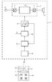
- the figure shows a hearing aid 1 with a microphone 2 for receiving an acoustic input signal and conversion into an electrical signal, a signal processing unit 3 for processing and frequency-dependent amplification of the electrical signal and a receiver 4 for converting the processed and amplified signal into an acoustic output signal.
- the signal processing unit 3 in the embodiment is implemented in digital circuit technology and therefore comprises an A / D converter 5 for converting the electrical input signal into a digital input signal and a D / A converter 7 for converting the processed digital signal into an analog output signal. In between, the signal processing takes place in a digital circuit technology realized signal processing unit 6.
- the digital components of the hearing aid 1 are clocked by a clock generator 8.
- a clock generator 8 By Frequenzvervieltigtiger individual components can be clocked at multiples of this clock frequency. Since the clock generator contains only a simply constructed oscillator and no quartz, the predetermined clock frequency can be maintained with a maximum deviation of +/- 5% from the predetermined setpoint. However, this fluctuation range is too high for certain digital filters included in the digital signal processing unit 6.
- the clock frequency generated by the clock generator 8 will be stabilized according to the invention such that at least temporarily the deviation of up to +/- 5% from the setpoint is substantially limited.
- a remote control 9 for remote control of the hearing aid 1.
- the remote control 9 in the exemplary embodiment comprises a clock generator 12, which comprises a quartz 13.
- the clock frequency can thus be kept very accurate.
- the period of the clock pulses which are generated and emitted by the remote control 1 is preferably very long, for example 10 seconds.
- the hearing aid 1 in turn comprises a receiving unit 14 for receiving the output from the remote control 9 clock signal.
- the external clock signal is finally supplied to a counter 15 which counts the number of clocks of the clock generator 8 during a period of the external clock signal.
- the counter 15 reaches a count of 210,000 during a period of the external clock signal of 10 seconds.
- the count would have after 10 sec, however, be 200,000.
- the clock frequency of the clock generator 8 is therefore readjusted accordingly.
- a comparison control unit 16 is present in the hearing aid 1, in addition to the count and a setpoint S received. From the comparison of the counter reading with the reference value, the comparison and control unit 16 generates a control signal for slowing the clock frequency of the clock generator 8.
- the count is averaged over several periods of the external clock signal before a control signal for correcting the clock frequency of the clock generator 8 is generated.
- a control signal for correcting the clock frequency of the clock generator 8 is generated.
Abstract
Description
Die Erfindung betrifft ein Hörhilfegerät mit einem Eingangswandler zur Aufnahme eines Eingangssignals und Wandlung in ein elektrisches Eingangssignal, einer Signalverarbeitungseinheit zur Verarbeitung und frequenzabhängigen Verstärkung des elektrischen Eingangssignals, einem Ausgangswandler zum Erzeugen eines von einem Benutzer als akustisches Signal wahrnehmbaren Ausgangssignals und einem Taktelement zum Erzeugen eines Systemtakts, wobei die tatsächliche Systemtaktfrequenz von einer vorgegebenen Systemtaktfrequenz bauteilbedingt innerhalb einer bestimmten Schwankungsbreite von der vorgegebenen Systemtaktfrequenz abweicht. Ferner betrifft die Erfindung ein Hörhilfegerätesystem mit einem derartigen Hörhilfegerät und einem externen Sender. Weiterhin betrifft die Erfindung ein Verfahren zum Betrieb eines derartigen Hörhilfegerätes.The invention relates to a hearing aid with an input transducer for receiving an input signal and conversion to an electrical input signal, a signal processing unit for processing and frequency-dependent amplification of the electrical input signal, an output transducer for generating a perceptible by a user as an acoustic signal output signal and a clock element for generating a system clock wherein the actual system clock frequency deviates from a predetermined system clock frequency due to the component within a certain fluctuation range from the predetermined system clock frequency. Furthermore, the invention relates to a hearing aid system with such a hearing aid and an external transmitter. Furthermore, the invention relates to a method for operating such a hearing aid.
In hinter oder in dem Ohr tragbaren digitalen Hörhilfegeräten kann aufgrund der angestrebten Miniaturisierung der Systemtakt nicht mit einem Quarz, sondern lediglich mit einem Oszillator erzeugt werden, da eine Quarzsteuerung zu viel Platz beanspruchen würde. Durch höhere, zum Teil temperaturabhängige Bauteiltoleranzen beträgt die Schwankungsbreite, innerhalb der die Taktfrequenz der Hörhilfegeräte von einem vorgegebenen Sollwert abweichen kann, daher +/- 5%, das heißt, bei nominell 20 KHz Taktfrequenz kann der tatsächliche Wert zwischen 19 KHz und 21 KHz liegen. Dies stellt vor allem für Filter ein Problem dar, die rein akustisch/physikalische Phänomene, z.B. Hörerresonanzen, Effekte durch den Schallschlauch und ähnliches modifizieren sollen. Die Parameter dieser Filter, z.B. der Frequenzgang, sind bei einer digitalen Realisierung direkt abhängig von der Abtastrate des Eingangssignals und damit von der Taktfrequenz. Soll z.B. eine schmale Hörerresonanz bei physikalisch durch den Hörer gegebenen 8 KHz mit einem digitalen Filter gedämpft werden, so würde eine ungenaue Abtastrate nur Angaben für einen Ziel-Frequenzbereich von 8 KHz +/- 5%, also 7,6 KHz bis 8,4 KHz erlauben. Dies ist jedoch zu ungenau. Aus dem genannten Grund werden derartige Filter bisher nicht eingesetzt.In behind or in the ear portable digital hearing aids, the system clock can not be generated with a quartz, but only with an oscillator due to the desired miniaturization, as a quartz control would take up too much space. Due to higher, sometimes temperature-dependent component tolerances, the fluctuation range within which the clock frequency of the hearing aid can deviate from a predetermined target value, therefore +/- 5%, that is, at a nominal 20 KHz clock frequency, the actual value between 19 KHz and 21 KHz , This is a problem, especially for filters, which are intended to modify purely acoustic / physical phenomena, for example, receiver resonance, effects through the sound tube and the like. The parameters of these filters, such as the frequency response, are directly dependent on the sampling rate of the input signal and thus of the clock frequency in a digital implementation. If, for example, a narrow receiver resonance is to be attenuated with a digital filter given physical 8 kHz by the listener, then For example, an inaccurate sampling rate would only allow for a target frequency range of 8 KHz +/- 5%, that is 7.6 KHz to 8.4 KHz. However, this is too inaccurate. For the above reason, such filters are not used yet.
Aus der DE 100 48 341 C1 ist ein Hörgerät bekannt, bei dem eine automatische Auswahl des aktiven Hörprogramms in Abhängigkeit von der Tageszeit erfolgt. Das Hörgerät ist hierfür mit einer internen Uhr ausgestattet. Zur genauen und komfortablen Einstellung der aktuellen Uhrzeit ist das Hörgerät vorzugsweise zum Empfang eines externen Zeitsignals (z.B. DCF 77) eines Zeitsignalsenders ausgebildet. Eine manuelle Einstellung der Uhrzeit, z. B. zur Umstellung zwischen Sommerzeit und Winterzeit, entfällt damit.From DE 100 48 341 C1, a hearing aid is known, in which an automatic selection of the active hearing program takes place as a function of the time of day. The hearing aid is equipped with an internal clock for this purpose. For accurate and convenient setting of the current time, the hearing aid is preferably designed to receive an external time signal (e.g., DCF 77) of a time signal transmitter. A manual setting of the time, z. For example, to switch between summer time and winter time, it eliminates.
Aus der EP 1 104 645 B1 ist ein Hörgerät mit einem Mikrofon, einer Signalverarbeitungseinheit, einem Hörer und einem Detektorelement zur Ermittlung von elektromagnetischen Störsignalen bekannt, wobei ein in Abhängigkeit von den erkannten Störsignalen konfigurierbares Filterelement zur Unterdrückung der Störsignale vorhanden ist. Das bekannte Hörgerät ist in digitaler Schaltungstechnik ausgeführt und weist hierfür einen Taktgenerator auf. Bei einem erkannten, getakteten Störsignal wird die bisherige Taktfrequenz durch die Taktfrequenz des Störsignals oder eines Vielfachen dieser Taktfrequenz ersetzt. Die Taktfrequenz ist somit von der Taktfrequenz des Störsignals bestimmt.A hearing device with a microphone, a signal processing unit, a receiver and a detector element for detecting electromagnetic interference signals is known from EP 1 104 645 B1, wherein a filter element which can be configured as a function of the detected interference signals is present for suppressing the interference signals. The known hearing aid is implemented in digital circuit technology and has a clock generator for this purpose. In a detected, clocked interference signal, the previous clock frequency is replaced by the clock frequency of the interference signal or a multiple of this clock frequency. The clock frequency is thus determined by the clock frequency of the interference signal.
Aufgabe der vorliegenden Erfindung ist es, bei einem digitalen Hörhilfegerät die Schwankungsbreite einer vorgegebenen Taktfrequenz zu verringern.The object of the present invention is to reduce the fluctuation range of a predetermined clock frequency in a digital hearing aid device.
Diese Aufgabe wird bei einem Hörhilfegerät einem Eingangswandler zur Aufnahme eines Eingangssignals und Wandlung in ein elektrisches Eingangssignal, einer Signalverarbeitungseinheit zur Verarbeitung und frequenzabhängigen Verstärkung des elektrischen Eingangssignals und einem Ausgangswandler zum Erzeugen eines von einem Benutzer als akustisches Signal wahrnehmbaren Ausgangssignals und mit einem Taktelement zum Erzeugen eines Systemtakts, wobei die tatsächliche Systemtaktfrequenz von einer vorgegebenen Systemtaktfrequenz bauteilbedingt innerhalb einer bestimmten Schwankungsbreite von der vorgegebenen Systemtaktfrequenz abweicht, gelöst durch ein extern erzeugtes, im Hörhilfegerät empfangbares, periodisches elektromagnetisches Signal zur Stabilisierung der tatsächlichen Systemtaktfrequenz, das derart verwendbar ist, dass sich die Abweichung der tatsächlichen Systemtaktfrequenz von der vorgegebenen Systemtaktfrequenz verringert.This object is achieved in a hearing aid to an input transducer for receiving an input signal and conversion to an electrical input signal, a signal processing unit for processing and frequency-dependent amplification of the electrical input signal and an output transducer for generating a user as an acoustic signal perceptible output signal and with a clock element for generating a system clock, wherein the actual system clock frequency deviates from a predetermined system clock frequency due to the component within a certain range of variation from the predetermined system clock frequency, solved by an externally generated, in the hearing aid device receivable, periodic electromagnetic signal for stabilizing the actual system clock frequency, the is usable such that the deviation of the actual system clock frequency from the predetermined system clock frequency decreases.
Die Aufgabe wird ferner gelöst durch ein Verfahren zum Betrieb eines Hörhilfegerätes mit einem Eingangswandler zur Aufnahme eines Eingangssignals und Wandlung in ein elektrisches Eingangssignal, einer Signalverarbeitungseinheit zur Verarbeitung und frequenzabhängigen Verstärkung des elektrischen Eingangssignals und einem Ausgangswandler zum Erzeugen eines von einem Benutzer als akustisches Signal wahrnehmbaren Ausgangssignals und mit einem Taktelement zum Erzeugen eines Systemtakts, wobei die tatsächliche Systemtaktfrequenz von einer vorgegebenen Systemtaktfrequenz bauteilbedingt innerhalb einer bestimmten Schwankungsbreite von der vorgegebenen Systemtaktfrequenz abweicht, mit folgenden Schritten:
- Empfang eines periodischen elektromagnetischen Signals eines externen Senders, dessen Periode bekannt ist,
- Zählen der tatsächlichen Taktimpulse des Systemtaktes des Hörhilfegerätes während wenigstens einer Periode des von dem externen Sender abgegebenen Signals,
- Vergleich des Zählergebnisses mit einem Sollwert
- Nachjustieren des Systemtakts zur Angleichung der tatsächlichen Anzahl der Taktimpulse während einer Periode des von dem externen Sender abgegebenen Signals mit dem Sollwert.
- Receiving a periodic electromagnetic signal from an external transmitter whose period is known
- Counting the actual clock pulses of the system clock of the hearing aid during at least one period of the signal output from the external transmitter,
- Comparison of the counting result with a setpoint
- Readjusting the system clock to equalize the actual number of clock pulses during a period of the signal output from the external transmitter with the setpoint.
Bei einem Hörhilfegerät wird mittels eines Eingangswandlers ein Eingangssignal aufgenommen und in ein elektrisches Eingangssignal überführt. Üblicherweise dient als Eingangswandler wenigstens ein Mikrofon, welches ein akustisches Eingangssignal aufnimmt. Moderne Hörhilfegeräte umfassen häufig ein Mikrofonsystem mit mehreren Mikrofonen, um einen von der Einfallsrichtung akustischer Signale abhängigen Empfang, eine Richtcharakteristik, zu erreichen. Die Eingangswandler können jedoch auch eine Telefonspule oder eine Antenne umfassen zur Aufnahme elektromagnetischer Eingangssignale. Die durch den Eingangswandler in elektrische Eingangssignale gewandelten Eingangssignale werden zur Weiterverarbeitung und Verstärkung einer Signalverarbeitungseinheit zugeführt. Die Weiterverarbeitung und Verstärkung erfolgt zum Ausgleich des individuellen Hörverlustes eines Hörhilfegeräteträgers in der Regel in Abhängigkeit der Signalfrequenz. Die Signalverarbeitungseinheit gibt ein elektrisches Ausgangssignal ab, welches über einen Ausgangswandler dem Gehör des Hörhilfegeräteträgers zugeführt wird, so dass dieser das Ausgangssignal als akustisches Signal wahrnimmt. Als Ausgangswandler werden üblicherweise Hörer verwendet, die ein akustisches Ausgangssignal erzeugen. Es sind jedoch auch Ausgangswandler zur Erzeugung mechanischer Schwingungen bekannt, die direkt bestimmte Teile des Gehörs, wie beispielsweise die Gehörknöchelchen, zu Schwingungen anregen. Weiterhin sind Ausgangswandler bekannt, die direkt Nervenzellen des Gehörs stimulieren.In a hearing aid, an input signal is recorded by means of an input transducer and converted into an electrical input signal. Usually serves as an input transducer at least one microphone, which is an acoustic input signal receives. Modern hearing aids often comprise a microphone system with a plurality of microphones in order to achieve a direction dependent on the direction of arrival of acoustic signals reception, a directional characteristic. However, the input transducers may also include a telecoil or antenna for receiving electromagnetic input signals. The input signals converted by the input transducer into electrical input signals are fed to a signal processing unit for further processing and amplification. The further processing and amplification takes place to compensate for the individual hearing loss of a hearing aid wearer, as a rule, as a function of the signal frequency. The signal processing unit outputs an electrical output signal, which is supplied via an output transducer to the hearing of the hearing aid wearer, so that the latter perceives the output signal as an acoustic signal. As output transducers usually listeners are used, which generate an acoustic output signal. However, output transducers for generating mechanical vibrations are also known, which directly excite certain parts of the ear, such as the ossicles, to vibrate. Furthermore, output transducers are known which directly stimulate neurons of the ear.
Das Hörhilfegerät gemäß der Erfindung ist in digitaler Schaltungstechnik ausgeführt und umfasst daher ein Taktelement zum Erzeugen des Systemtakts. Da aufgrund der angestrebten Miniaturisierung von Hörhilfegeräten ein Quarz nicht verwendet werden kann, wird bei dem Hörhilfegerät gemäß der Erfindung ein gewöhnlicher Oszillator verwendet. Dieser hat jedoch den Nachteil, dass eine vorgegebene Systemtaktfrequenz tatsächlich nur mit einer Abweichung von ca. +/- 5% von dem vorgegebenen Wert erreicht werden kann. Da diese Abweichung für die Anwendung bestimmter Filter nicht akzeptabel ist, wird gemäß der Erfindung vorgeschlagen, ein genaueres, z.B. mit einem Quarz stabilisiertes, externes Taktsignal zur Stabilisierung des internen Systemtakts zu verwenden. Dieses Taktsignal wird in einem externen Gerät, beispielsweise einer Fernbedienung für das Hörhilfegerät, erzeugt und als elektromagnetisches Signal drahtlos auf das Hörhilfegerät übertragen. Ist die Taktfrequenz dieses externen Taktes bekannt, so kann damit die Taktfrequenz des Hörhilfegerätes verglichen und nachjustiert werden. Die Abweichung von dem vorgegebenen Wert wird dadurch deutlich kleiner als +/- 5%, beispielsweise nur noch +/- 0,5%. Durch den stabilisierten Takt mit der dadurch erreichten, geringen Abweichung der Taktfrequenz von dem Sollwert lassen sich dann im Hörhilfegerät realisierte digitale Filter sehr viel genauer einstellen.The hearing aid according to the invention is implemented in digital circuit technology and therefore comprises a clock element for generating the system clock. Since quartz can not be used due to the intended miniaturization of hearing aids, the hearing aid according to the invention uses a common oscillator. However, this has the disadvantage that a predetermined system clock frequency can actually only be achieved with a deviation of about +/- 5% of the predetermined value. Since this deviation is not acceptable for the application of certain filters, it is proposed according to the invention to use a more precise, for example stabilized with a quartz, external clock signal for stabilizing the internal system clock. This clock signal is generated in an external device, such as a remote control for the hearing aid, and as electromagnetic Transfer the signal wirelessly to the hearing aid. If the clock frequency of this external clock is known, then the clock frequency of the hearing aid can be compared and readjusted. The deviation from the specified value is thereby significantly less than +/- 5%, for example, only +/- 0.5%. Due to the stabilized clock with the achieved thereby, small deviation of the clock frequency of the setpoint then realized in the hearing aid digital filters can be set much more accurate.
Zur Erzeugung des Taktes wird bei Hörhilfegeräten häufig ein so genannter Ringoszillator verwendet, der sich insbesondere durch einen geringen Stromverbrauch auszeichnet. Dieser ist im Wesentlichen aus mehreren hintereinander geschalteten Invertern aufgebaut, wobei der Ausgang des letzten Inverters der Kette auf den Eingang des ersten Inverters rückgekoppelt ist. Die Feinjustierung des Taktes erfolgt dabei über eine einstellbare Stromquelle, welche die Inverter mit Strom versorgt. Der Strom dieser Stromquelle wird üblicherweise nach der Herstellung eines Hörhilfegerätes einmal eingestellt. Durch die Umgebungstemperatur, Alterungseinflüsse, Bauteiltoleranzen usw. kommt es jedoch während des Betriebes des Hörhilfegerätes zu den genannten Abweichungen von bis zu +/- 5% vom eingestellten Sollwert. Im Zusammenhang mit der Erfindung wird bei dieser Methode der Takterzeugung die Stromquelle während des Betriebs des Hörhilfegeräts nachjustiert.For generating the clock, a so-called ring oscillator is often used in hearing aids, which is characterized in particular by a low power consumption. This is composed essentially of several series-connected inverters, wherein the output of the last inverter of the chain is fed back to the input of the first inverter. The fine adjustment of the clock is done via an adjustable power source, which supplies the inverter with power. The current of this power source is usually set once after the production of a hearing aid. Due to the ambient temperature, aging influences, component tolerances, etc., however, during operation of the hearing aid device, the abovementioned deviations of up to +/- 5% from the set desired value occur. In connection with the invention, the current source is readjusted during the operation of the hearing aid in this method of clock generation.
Die Erfindung ist nicht auf den beispielhaft genannten Ringoszillator zur Takterzeugung beschränkt. Vielmehr ist dem Fachmann eine Vielzahl weiterer Methoden zur Takterzeugung bei Hörhilfegeräten bekannt. Auch bei den bekannten weiteren Methoden kann in der Regel durch steuerbare Strom- oder Spannungsquellen, Widerstände, Kapazitäten oder Induktivitäten die Taktfrequenz nachjustiert werden.The invention is not limited to the exemplified ring oscillator for clock generation. Rather, the person skilled in a variety of other methods for clock generation in hearing aids known. In the known further methods, the clock frequency can generally be readjusted by controllable current or voltage sources, resistors, capacitances or inductances.
Eine Ausführungsform der Erfindung sieht eine Quarz-Armbanduhr als externen Sender vor, die zusätzlich mit einer Sendeeinheit versehen ist. Diese bedarf gegenüber einer herkömmlichen Quarz-Armbanduhr nur geringfügiger Modifikationen und kann unauffällig in der für diese Anwendung notwendigen Entfernung zu dem Hörhilfegerät getragen werden.An embodiment of the invention provides a quartz wristwatch as an external transmitter, which is additionally provided with a transmitting unit. This requires compared to a conventional one Quartz wristwatch with only minor modifications and can be worn inconspicuously in the distance to the hearing aid for this application.
Bei einer bevorzugten Ausführungsform der Erfindung wird ein in vielen Ländern ausgesendetes Zeitsignal für Funkuhren, in Deutschland das DCF77-Zeitsignal, als externes Taktsignal verwendet, um damit den hörhilfegeräteinternen Systemtakt zu stabilisieren. Ein derartiges Zeitsignal wird in vielen Ländern flächendeckend und mit sehr großer Genauigkeit der Taktperioden ausgestrahlt. Auch entsprechende Empfänger sind preiswert verfügbar.In a preferred embodiment of the invention, a time signal for radio clocks sent out in many countries, in Germany the DCF77 time signal, is used as an external clock signal in order to stabilize the hearing aid device-internal system clock. Such a time signal is broadcast in many countries nationwide and with very high accuracy of the clock periods. Also corresponding receivers are available at low cost.
Eine Weiterbildung der Erfindung sieht vor, zum Nachjustieren des Systemtaktes eine Mittelung über mehrere Zählungen der tatsächlichen Taktimpulse des Hörhilfegeräte-Taktes während wenigstens einer Periode des externen Taktsignals und die entsprechenden Vergleiche mit dem Sollwert durchzuführen. Damit lässt sich eine noch genauere Einstellung des Systemtaktes erreichen. Störungen beim Empfang des externen Signals werden dadurch ausgeglichen.A development of the invention provides to readjust the system clock an averaging over several counts of the actual clock pulses of the hearing aid clock during at least one period of the external clock signal and perform the corresponding comparisons with the setpoint. This allows an even more accurate adjustment of the system clock. Disturbances in the reception of the external signal are thereby compensated.
Die Erfindung wird nachfolgend anhand eines Ausführungsbeispiels näher erläutert. Dabei zeigt die Figur ein Hörhilfegerät 1 mit einem Mikrofon 2 zur Aufnahme eines akustischen Eingangssignals und Wandlung in ein elektrisches Signal, einer Signalverarbeitungseinheit 3 zur Verarbeitung und frequenzabhängigen Verstärkung des elektrischen Signals und einem Hörer 4 zur Wandlung des verarbeiteten und verstärkten Signals in ein akustisches Ausgangssignal, das dem Gehör eines Hörhilfegeräteträgers zugeführt wird. Die Signalverarbeitungseinheit 3 im Ausführungsbeispiel ist in digitaler Schaltungstechnik ausgeführt und umfasst daher einen A/D-Wandler 5 zur Wandlung des elektrischen Eingangssignals in ein digitales Eingangssignal sowie einen D/A-Wandler 7 zur Wandlung des verarbeiteten, digitalen Signals in ein analoges Ausgangssignal. Dazwischen erfolgt die Signalverarbeitung in einer in digitaler Schaltungstechnik realisierten Signalverarbeitungseinheit 6.The invention will be explained in more detail with reference to an embodiment. The figure shows a
Die digitalen Bauelemente des Hörhilfegerätes 1 werden durch einen Taktgenerator 8 getaktet. Durch Frequenzvervielfältiger können einzelne Bauteile auch mit Vielfachen dieser Taktfrequenz getaktet sein. Da der Taktgenerator lediglich einen einfach aufgebauten Oszillator und keinen Quarz enthält, kann die vorgegebene Taktfrequenz mit einer maximalen Abweichung von +/- 5% von dem vorgegebenen Sollwert eingehalten werden. Diese Schwankungsbreite ist für bestimmte, in der digitalen Signalverarbeitungseinheit 6 enthaltene digitale Filter jedoch zu hoch.The digital components of the
Die von dem Taktgenerator 8 erzeugte Taktfrequenz wird gemäß der Erfindung derart stabilisiert werden, dass zumindest zeitweise die Abweichung von bis zu +/- 5% vom Sollwert wesentlich eingeschränkt wird. Hierfür dient im Ausführungsbeispiel eine Fernbedienung 9 zur Fernbedienung des Hörhilfegerätes 1. Diese umfasst die mit "1" bis "4" beschrifteten Programmwahltasten 10 zur Anpassung der Signalverarbeitung im Hörhilfegerät 1 an unterschiedliche Hörumgebungen sowie eine Lautstärke-Schaltwippe 11 zur Lautstärkeeinstellung. Neben diesen üblichen Komponenten einer Fernbedienung umfasst die Fernbedienung 9 im Ausführungsbeispiel einen Taktgenerator 12, der einen Quarz 13 umfasst. Die Taktfrequenz kann damit sehr genau eingehalten werden. Die Periode der Taktimpulse, die von der Fernbedienung 1 erzeugt und abgestrahlt werden, ist vorzugsweise sehr lang, beispielsweise 10 sec. Dadurch wird zum Senden des Taktsignals kaum Energie benötigt. Das Hörhilfegerät 1 umfasst seinerseits eine Empfangseinheit 14 zum Empfang des von der Fernbedienung 9 abgegebenen Taktsignals. Das externe Taktsignal wird schließlich einem Zähler 15 zugeführt, der die Anzahl der Takte des Taktgenerators 8 während einer Periode des externen Taktsignals zählt. Z.B. erreicht der Zähler 15 während einer Periode des externen Taktsignals von 10 sec einen Zählerstand von 210.000. Bei einem Sollwert der Systemtaktfrequenz von 20 KHz müsste der Zählerstand nach 10 sec jedoch 200.000 betragen. Die Taktfrequenz des Taktgenerators 8 wird daher entsprechend nachjustiert. Hierfür ist im Hörhilfegerät 1 eine Vergleichs-Steuereinheit 16 vorhanden, in die neben dem Zählerstand auch ein Sollwert S eingeht. Aus dem Vergleich des Zählerstandes mit dem Sollwert erzeugt die Vergleichs- und Steuereinheit 16 ein Steuersignal zur Verlangsamung der Taktfrequenz des Taktgenerators 8.The clock frequency generated by the
Bei einer bevorzugten Weiterbildung der Erfindung wird der Zählerstand über mehrere Perioden des externen Taktsignals gemittelt, bevor ein Steuersignal zur Korrektur der Taktfrequenz des Taktgenerators 8 erzeugt wird. Dadurch wird eine noch genauere Einstellung des Systemtaktes des Hörhilfegerätes 1 erreicht. Insbesondere werden Störungen beim Empfangen des Externen Taktsignals ausgeglichen.In a preferred embodiment of the invention, the count is averaged over several periods of the external clock signal before a control signal for correcting the clock frequency of the
Claims (9)
Applications Claiming Priority (1)
| Application Number | Priority Date | Filing Date | Title |
|---|---|---|---|
| DE102004037379 | 2004-08-02 |
Publications (3)
| Publication Number | Publication Date |
|---|---|
| EP1624723A2 true EP1624723A2 (en) | 2006-02-08 |
| EP1624723A3 EP1624723A3 (en) | 2009-05-20 |
| EP1624723B1 EP1624723B1 (en) | 2012-05-30 |
Family
ID=35415260
Family Applications (1)
| Application Number | Title | Priority Date | Filing Date |
|---|---|---|---|
| EP05107054A Not-in-force EP1624723B1 (en) | 2004-08-02 | 2005-07-29 | Stabilisation of the system-clock pulse in a hearing aid |
Country Status (3)
| Country | Link |
|---|---|
| US (1) | US7577268B2 (en) |
| EP (1) | EP1624723B1 (en) |
| DK (1) | DK1624723T3 (en) |
Cited By (1)
| Publication number | Priority date | Publication date | Assignee | Title |
|---|---|---|---|---|
| US8588443B2 (en) | 2006-05-16 | 2013-11-19 | Phonak Ag | Hearing system with network time |
Families Citing this family (3)
| Publication number | Priority date | Publication date | Assignee | Title |
|---|---|---|---|---|
| CN101690265A (en) * | 2007-06-13 | 2010-03-31 | 唯听助听器公司 | A hearing aid adapted for issuing a notification and a method for issuing a notification |
| US20140192626A1 (en) * | 2011-03-02 | 2014-07-10 | Royal Hali Iplik Tekstil Mobilya Sanayi Ve Ticaret Anonim Sirketi | Talking Dome Watch for the Visually Impaired |
| US11878177B2 (en) | 2018-10-10 | 2024-01-23 | Cochlear Limited | Implantable medical device short-range radio synchronization |
Citations (4)
| Publication number | Priority date | Publication date | Assignee | Title |
|---|---|---|---|---|
| DE10048341C1 (en) | 2000-09-29 | 2002-04-18 | Siemens Audiologische Technik | Operating hearing aid involves receiving signal from external transmitter in hearing aid in close proximity to transmitter, associating received signal to hearing situation adapting to situation |
| EP1104645B1 (en) | 1998-08-13 | 2003-02-05 | Siemens Audiologische Technik GmbH | Hearing aid comprising a device for suppressing electromagnetic interference signals and method for suppressing electromagnetic interference signals in hearing aids |
| US20040037442A1 (en) | 2000-07-14 | 2004-02-26 | Gn Resound A/S | Synchronised binaural hearing system |
| US6768802B1 (en) | 1999-10-15 | 2004-07-27 | Phonak Ag | Binaural synchronization |
Family Cites Families (7)
| Publication number | Priority date | Publication date | Assignee | Title |
|---|---|---|---|---|
| WO1993004425A1 (en) * | 1991-08-13 | 1993-03-04 | Universal Photonix, Inc. | System for remotely validating the identity of indivuals and determining their locations |
| US20050036637A1 (en) * | 1999-09-02 | 2005-02-17 | Beltone Netherlands B.V. | Automatic adjusting hearing aid |
| US6816600B1 (en) * | 2000-01-13 | 2004-11-09 | Phonak Ag | Remote control for a hearing aid, and applicable hearing aid |
| NL1020387C2 (en) * | 2002-04-15 | 2003-10-17 | Gatsometer Bv | Method for remotely synchronizing a traffic monitoring system and a traffic monitoring system equipped for this purpose. |
| DE10245556B3 (en) * | 2002-09-30 | 2004-04-22 | Siemens Audiologische Technik Gmbh | Hearing aid or hearing aid system with a clock generator and method for their operation |
| US20040190737A1 (en) * | 2003-03-25 | 2004-09-30 | Volker Kuhnel | Method for recording information in a hearing device as well as a hearing device |
| DE102004025691B3 (en) * | 2004-05-26 | 2005-08-18 | Siemens Audiologische Technik Gmbh | Hearing aid or hearing aid system with operating device, has at least one operating element associated with different setting functions depending on results of signal analysis |
-
2005
- 2005-07-29 EP EP05107054A patent/EP1624723B1/en not_active Not-in-force
- 2005-07-29 DK DK05107054.8T patent/DK1624723T3/en active
- 2005-08-02 US US11/194,932 patent/US7577268B2/en not_active Expired - Fee Related
Patent Citations (4)
| Publication number | Priority date | Publication date | Assignee | Title |
|---|---|---|---|---|
| EP1104645B1 (en) | 1998-08-13 | 2003-02-05 | Siemens Audiologische Technik GmbH | Hearing aid comprising a device for suppressing electromagnetic interference signals and method for suppressing electromagnetic interference signals in hearing aids |
| US6768802B1 (en) | 1999-10-15 | 2004-07-27 | Phonak Ag | Binaural synchronization |
| US20040037442A1 (en) | 2000-07-14 | 2004-02-26 | Gn Resound A/S | Synchronised binaural hearing system |
| DE10048341C1 (en) | 2000-09-29 | 2002-04-18 | Siemens Audiologische Technik | Operating hearing aid involves receiving signal from external transmitter in hearing aid in close proximity to transmitter, associating received signal to hearing situation adapting to situation |
Cited By (1)
| Publication number | Priority date | Publication date | Assignee | Title |
|---|---|---|---|---|
| US8588443B2 (en) | 2006-05-16 | 2013-11-19 | Phonak Ag | Hearing system with network time |
Also Published As
| Publication number | Publication date |
|---|---|
| DK1624723T3 (en) | 2012-09-03 |
| US20060023906A1 (en) | 2006-02-02 |
| US7577268B2 (en) | 2009-08-18 |
| EP1624723B1 (en) | 2012-05-30 |
| EP1624723A3 (en) | 2009-05-20 |
Similar Documents
| Publication | Publication Date | Title |
|---|---|---|
| EP1619929B1 (en) | Hearing aid system as well as method to operate a hearing aid system during audio reception | |
| EP1737270B2 (en) | Hearing assistance providing feedback suppression | |
| DE102007046437B4 (en) | Fully automatic switching on / off for hearing aids | |
| EP2150076B1 (en) | Device for preventing loss of hearing aids | |
| DE60318335T2 (en) | HEARING DEVICE SYSTEM, HEARING DEVICE AND METHOD FOR PROCESSING AUDIO SIGNALS | |
| US4995085A (en) | Hearing aid adaptable for telephone listening | |
| EP1651006A2 (en) | Hearing aid with line loop to compensate the inductive disturbance fields | |
| EP1628504B1 (en) | Energy saving mode in hearing aids | |
| EP1643802A2 (en) | Transmission of signals between hearing aids | |
| EP2229010A2 (en) | Method for compensating for interference in a hearing aid, hearing aid and method for adjusting same | |
| EP1624723B1 (en) | Stabilisation of the system-clock pulse in a hearing aid | |
| EP1624721A2 (en) | Freely configurable information signals in hearing-aids | |
| DE102009021855A1 (en) | A method for acclimating a programmable hearing device and associated hearing device | |
| DE102007001538B4 (en) | Hearing device with automatic self-trim and corresponding method | |
| EP1841286A2 (en) | Hearing aid with adaptive starting values of parameters | |
| DE102010012623B4 (en) | Method for transmitting data between a hearing aid and an external unit and associated arrangement | |
| EP1406468B1 (en) | Hearing-aid device or hearing-aid system with a clock signal generator | |
| EP1883272A2 (en) | Hearing device for musicians | |
| EP1624722A2 (en) | Hearing aid with time check | |
| EP2023667A2 (en) | Method for adjusting a hearing aid with a perceptive model for binaural hearing and corresponding hearing system | |
| EP1771037A2 (en) | Hearing-aid device with digital control elements | |
| EP2234411A1 (en) | Method for operating a hearing aid with reinforced feedback compensation and hearing aid | |
| DE102008055726A1 (en) | Hearing device e.g. concha-hearing device, for assisting hearing-impaired person, has microphone location effect-filter compensating positions of microphones, such that receiving signal is not influenced by microphone location effect-filter | |
| DE102008064382A1 (en) | Hearing device i.e. behind-the-ear hearing device, has transposition device for transposing part of frequency range of output signal, and control device releasing transposing of transposition device in cent steps | |
| DE102020214329A1 (en) | Methods to support the use of a hearing aid and hearing aid |
Legal Events
| Date | Code | Title | Description |
|---|---|---|---|
| PUAI | Public reference made under article 153(3) epc to a published international application that has entered the european phase |
Free format text: ORIGINAL CODE: 0009012 |
|
| AK | Designated contracting states |
Kind code of ref document: A2 Designated state(s): AT BE BG CH CY CZ DE DK EE ES FI FR GB GR HU IE IS IT LI LT LU LV MC NL PL PT RO SE SI SK TR |
|
| AX | Request for extension of the european patent |
Extension state: AL BA HR MK YU |
|
| PUAL | Search report despatched |
Free format text: ORIGINAL CODE: 0009013 |
|
| AK | Designated contracting states |
Kind code of ref document: A3 Designated state(s): AT BE BG CH CY CZ DE DK EE ES FI FR GB GR HU IE IS IT LI LT LU LV MC NL PL PT RO SE SI SK TR |
|
| AX | Request for extension of the european patent |
Extension state: AL BA HR MK YU |
|
| 17P | Request for examination filed |
Effective date: 20091117 |
|
| AKX | Designation fees paid |
Designated state(s): CH DE DK FR GB LI |
|
| 17Q | First examination report despatched |
Effective date: 20110330 |
|
| GRAP | Despatch of communication of intention to grant a patent |
Free format text: ORIGINAL CODE: EPIDOSNIGR1 |
|
| GRAS | Grant fee paid |
Free format text: ORIGINAL CODE: EPIDOSNIGR3 |
|
| GRAA | (expected) grant |
Free format text: ORIGINAL CODE: 0009210 |
|
| AK | Designated contracting states |
Kind code of ref document: B1 Designated state(s): CH DE DK FR GB LI |
|
| REG | Reference to a national code |
Ref country code: GB Ref legal event code: FG4D Free format text: NOT ENGLISH |
|
| REG | Reference to a national code |
Ref country code: CH Ref legal event code: NV Representative=s name: SIEMENS SCHWEIZ AG Ref country code: CH Ref legal event code: EP |
|
| REG | Reference to a national code |
Ref country code: DE Ref legal event code: R096 Ref document number: 502005012754 Country of ref document: DE Effective date: 20120726 |
|
| REG | Reference to a national code |
Ref country code: DK Ref legal event code: T3 |
|
| PGFP | Annual fee paid to national office [announced via postgrant information from national office to epo] |
Ref country code: GB Payment date: 20120709 Year of fee payment: 8 |
|
| PGFP | Annual fee paid to national office [announced via postgrant information from national office to epo] |
Ref country code: DE Payment date: 20120906 Year of fee payment: 8 Ref country code: FR Payment date: 20120802 Year of fee payment: 8 |
|
| PGFP | Annual fee paid to national office [announced via postgrant information from national office to epo] |
Ref country code: CH Payment date: 20121011 Year of fee payment: 8 |
|
| PLBE | No opposition filed within time limit |
Free format text: ORIGINAL CODE: 0009261 |
|
| STAA | Information on the status of an ep patent application or granted ep patent |
Free format text: STATUS: NO OPPOSITION FILED WITHIN TIME LIMIT |
|
| 26N | No opposition filed |
Effective date: 20130301 |
|
| REG | Reference to a national code |
Ref country code: DE Ref legal event code: R097 Ref document number: 502005012754 Country of ref document: DE Effective date: 20130301 |
|
| REG | Reference to a national code |
Ref country code: DK Ref legal event code: EBP Effective date: 20130731 |
|
| REG | Reference to a national code |
Ref country code: CH Ref legal event code: PL |
|
| GBPC | Gb: european patent ceased through non-payment of renewal fee |
Effective date: 20130729 |
|
| REG | Reference to a national code |
Ref country code: DE Ref legal event code: R119 Ref document number: 502005012754 Country of ref document: DE Effective date: 20140201 |
|
| REG | Reference to a national code |
Ref country code: FR Ref legal event code: ST Effective date: 20140331 |
|
| PG25 | Lapsed in a contracting state [announced via postgrant information from national office to epo] |
Ref country code: DE Free format text: LAPSE BECAUSE OF NON-PAYMENT OF DUE FEES Effective date: 20140201 Ref country code: GB Free format text: LAPSE BECAUSE OF NON-PAYMENT OF DUE FEES Effective date: 20130729 Ref country code: LI Free format text: LAPSE BECAUSE OF NON-PAYMENT OF DUE FEES Effective date: 20130731 Ref country code: CH Free format text: LAPSE BECAUSE OF NON-PAYMENT OF DUE FEES Effective date: 20130731 |
|
| PG25 | Lapsed in a contracting state [announced via postgrant information from national office to epo] |
Ref country code: FR Free format text: LAPSE BECAUSE OF NON-PAYMENT OF DUE FEES Effective date: 20130731 |
|
| PG25 | Lapsed in a contracting state [announced via postgrant information from national office to epo] |
Ref country code: DK Free format text: LAPSE BECAUSE OF NON-PAYMENT OF DUE FEES Effective date: 20130731 |