EP1624548A2 - Output terminal assembly of alternator for vehicle - Google Patents
Output terminal assembly of alternator for vehicle Download PDFInfo
- Publication number
- EP1624548A2 EP1624548A2 EP04021483A EP04021483A EP1624548A2 EP 1624548 A2 EP1624548 A2 EP 1624548A2 EP 04021483 A EP04021483 A EP 04021483A EP 04021483 A EP04021483 A EP 04021483A EP 1624548 A2 EP1624548 A2 EP 1624548A2
- Authority
- EP
- European Patent Office
- Prior art keywords
- output terminal
- direction output
- axial direction
- rear bracket
- assembly
- Prior art date
- Legal status (The legal status is an assumption and is not a legal conclusion. Google has not performed a legal analysis and makes no representation as to the accuracy of the status listed.)
- Withdrawn
Links
Images


Classifications
-
- H—ELECTRICITY
- H02—GENERATION; CONVERSION OR DISTRIBUTION OF ELECTRIC POWER
- H02K—DYNAMO-ELECTRIC MACHINES
- H02K5/00—Casings; Enclosures; Supports
- H02K5/04—Casings or enclosures characterised by the shape, form or construction thereof
- H02K5/22—Auxiliary parts of casings not covered by groups H02K5/06-H02K5/20, e.g. shaped to form connection boxes or terminal boxes
- H02K5/225—Terminal boxes or connection arrangements
-
- H—ELECTRICITY
- H02—GENERATION; CONVERSION OR DISTRIBUTION OF ELECTRIC POWER
- H02K—DYNAMO-ELECTRIC MACHINES
- H02K15/00—Processes or apparatus specially adapted for manufacturing, assembling, maintaining or repairing of dynamo-electric machines
- H02K15/14—Casings; Enclosures; Supports
-
- H—ELECTRICITY
- H02—GENERATION; CONVERSION OR DISTRIBUTION OF ELECTRIC POWER
- H02K—DYNAMO-ELECTRIC MACHINES
- H02K3/00—Details of windings
- H02K3/32—Windings characterised by the shape, form or construction of the insulation
- H02K3/34—Windings characterised by the shape, form or construction of the insulation between conductors or between conductor and core, e.g. slot insulation
Definitions
- the present invention relates to an output terminal assembly of an alternator for a vehicle, and in particular to an improved output terminal assembly of an alternator for a vehicle capable of increasing of a contact area in order that a current density per unit area may be decreased and preventing a damage of a sealing member and decreasing an error during a fabrication by improving an assembling performance in such a manner that a contact structure between an axial direction output terminal and a radial direction output terminal is improved.
- a vehicle alternator includes a casing 30 that is formed of a rear bracket 10 having a shaft support part 11 and a front bracket 20, a shaft 60 that is installed in the interior of the casing wherein a pulley 40 is fixed to one end of the shaft 60, a rotor 70 fixed to the shaft, a fan 71 fixed to both sides of the rotor, a stator 50 fixed to an inner wall surface of the casing, a slip ring 52 that is fixed to the other end of the shaft for supplying current to the rotor, a pair of brushes 81 that contact with the slip ring, a brush assembly 80 that receives the brush, a rectifier assembly 90 that is electrically connected with the stator, a heat sink 91 that is engaged to the brush assembly, and a regulator 92 that is connected with the heat sink for adjusting the size of an alternating current voltage generated by the stator.
- an output terminal 100 in order to output the current generated based on the rotor 70 and the stator 50 to the outside.
- the output terminal 100 is formed of an axial direction output terminal 110, and a radius direction output terminal 120 connected from an outer portion of the same.
- the axial direction output terminal 110 includes a bolt head-shaped head part 111 and an extension part 112, a body part 113, and a thread part 115 formed at an end of the same.
- the radius direction output terminal 120 includes an assembling hole 123 inserted onto the thread part 115, an exposure part 121 formed in the opposite portion of the same, and an insulation mold 122 that surrounds the above elements.
- the thread part 115 of the axial direction output terminal 110 sequentially passes through a plate 94, a circuit board 93, an insulation pipe 95, and a heat sink 91 in an inner side of the bracket 10 and is exposed to the outside of the bracket 10.
- the assembling hole 123 of the radius direction output terminal 120 surrounded by the insulation mold 122 is inserted onto the thread part 115 and is engaged using a nut 116.
- the thread part 115 of the end of the same has less diameter as compared to the extension part 112 and the head part 111. Therefore, the contacting area is small when being assembled with the radius direction output terminal 120.
- the axial direction output terminal 110 for a desired contact between the terminal of the circuit board and the heat sink 91 may be inwardly pushed in the inner space of the bracket 10 by an assembling force, therefore a certain error may occur in the contact.
- an alternator that includes a casing formed of a rear bracket and a front bracket, a rotor fixed to the shaft in the interior of the casing, a stator fixed to an inner wall surface of the casing, a brush assembly, a rectifier assembly, a heat sink and a regulator
- an output terminal assembly of an alternator for a vehicle comprising an output terminal that includes an axial direction terminal engaged to the heat sink provided in an inner side of the rear bracket for outputting power to the outside, and a radius direction output terminal
- the axial direction output terminal includes a head part, an extension part, a body part, and a thread part formed at one end
- the radius direction output terminal includes an exposure part of an outer side end, an assembling hole formed at an inner end, and an insulation mold that covers the above elements; and wherein the extension part of the axial direction output terminal is inserted into an assembling hole of the radius direction output terminal, and the thread part of the axial direction output terminal is inserted from the outer side of the
- an alternator that includes a casing formed of a rear bracket and a front bracket, a rotor fixed to the shaft in the interior of the casing, a stator fixed to an inner wall surface of the casing, a brush assembly, a rectifier assembly, a heat sink and a regulator
- an output terminal assembly of an alternator for a vehicle comprising an output terminal that includes an axial direction terminal engaged to the heat sink provided in an inner side of the rear bracket for outputting power to the outside, and a radius direction output terminal, wherein the axial direction output terminal includes a head part, an extension part, a body part, and a thread part at one end, and the radius direction output terminal includes an exposure part at an outer end, and an assembling hole substantially larger for inserting the extension part; and wherein a body part of the radius direction output terminal and the head part of the axial direction output terminal are covered by an insulation mold in a state that the extension part of the axial direction terminal is inserted into the assembling hole of the radius direction
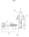
- Figure 3 is a disassembled cross sectional view illustrating an output terminal assembly according to an embodiment of the present invention
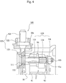
- Figure 4 is a cross sectional view illustrating an assembled state of an output terminal assembly according to the present invention.
- the alternator includes a casing 30 formed of a rear bracket 10 and a front bracket 20, a rotor 70 fixed to a shaft 60 in the interior of the casing, a stator 50 fixed to an inner wall surface of the casing, a brush assembly 80, a rectifier assembly 90, a heat sink 91, and a regulator 92.
- the output terminal 100 engaged with the heat 91 provided in the inner side of the rear bracket 10 for outputting power to the outside includes an axial direction output terminal 110, and a radius direction output terminal 120.
- the axial direction output terminal 110 includes a head part 111, an extension part 112, a body part 113, and a thread part 115 formed at one end of the same.
- the radius direction output terminal 120 includes an exposure part 121, an assembling hole 123 provided in the inner side of the exposure part 121 and formed in a large size for thereby inserting the extension part 112, and an insulation mold 112 that surrounds the above elements.
- the extension part 112 of the axial direction output terminal 110 is inserted into the assembling hole 123 of the radius direction output terminal 120, and the thread part 115 of the axial direction output terminal 110 is inserted from the outer side of the rear bracket 10 to the inner direction of the rear bracket 10 for thereby being fixed by a nut 116.
- the axial direction output terminal 110 includes the extension part 112 of the lower side of the head part, and a body part 113.
- the axial direction output terminal 110 further includes a heat sink contact part 114 at an intermediate portion.
- the diameter D1 of the extension part 112 and the diameter D2 of the heat sink contact part 114 are D2/D1 ⁇ 0.70.
- the diameter of the extension part 112 is larger than the diameter of the heat sink contact part 114.
- the rear bracket 10 has an assembling guide surface 10a in one side, and the exposure part 121 of the radius direction output terminal 120 contacts with the assembling guide surface 10a.
- the insulation mold 122 could be implemented in another method.
- the output terminal 100 includes an axial direction output terminal 110 engaged with a heat sink 91 provided in the inner side of the rear bracket 10 for outputting power to the outside, and a radius direction output terminal 120.
- the axial direction output terminal 110 includes a head part 111, an extension part 112, a body part 113, and a thread part 115 formed at one end.
- the radius direction output terminal 120 includes an exposure part 121 of an outer end, and an assembling hole 123 that is formed at an inner end of the opposite side for thereby inserting the extension part 112 thereinto.
- the insulation mold 122 surrounds the body part of the radius direction output terminal 120 and the head part 111 of the axial direction output terminal 110.
- the thread part 115 of the axial direction output terminal 110 is inserted from the outer side of the rear bracket 10 to the inner side of the rear bracket 10 for thereby being fixed using a nut 116.
- the axial direction output terminal 110 is inserted from the outer side of the rear bracket 10 to the inner direction of the rear bracket 10, the assembling of the output terminal is finished before the rear bracket 10 is assembled to the alternator.
- the head part of the axial direction output terminal is provided outside the rear bracket, it is possible to increase the contact area with respect to the radius direction output terminal without making the terminal hole of the heat sink larger.
- the radius direction output terminal is assembled with the axial direction output terminal before they are assembled with the bracket. Therefore, it is possible to assembly without a tight insertion, so that the insulation mold is not damaged.
- the radius direction output terminal When assembling the radius direction output terminal, since an assembling guide surface is formed on an outer surface of the bracket, the radius direction output terminal is always assembled in one direction for thereby enhancing an assembling performance.
Landscapes
- Engineering & Computer Science (AREA)
- Power Engineering (AREA)
- Manufacturing & Machinery (AREA)
- Motor Or Generator Frames (AREA)
- Synchronous Machinery (AREA)
- Manufacture Of Motors, Generators (AREA)
Abstract
Description
- The present invention relates to an output terminal assembly of an alternator for a vehicle, and in particular to an improved output terminal assembly of an alternator for a vehicle capable of increasing of a contact area in order that a current density per unit area may be decreased and preventing a damage of a sealing member and decreasing an error during a fabrication by improving an assembling performance in such a manner that a contact structure between an axial direction output terminal and a radial direction output terminal is improved.
- Generally, a vehicle alternator includes a
casing 30 that is formed of arear bracket 10 having a shaft supportpart 11 and afront bracket 20, ashaft 60 that is installed in the interior of the casing wherein apulley 40 is fixed to one end of theshaft 60, arotor 70 fixed to the shaft, afan 71 fixed to both sides of the rotor, astator 50 fixed to an inner wall surface of the casing, aslip ring 52 that is fixed to the other end of the shaft for supplying current to the rotor, a pair ofbrushes 81 that contact with the slip ring, abrush assembly 80 that receives the brush, arectifier assembly 90 that is electrically connected with the stator, aheat sink 91 that is engaged to the brush assembly, and aregulator 92 that is connected with the heat sink for adjusting the size of an alternating current voltage generated by the stator. - In addition, as shown in Figure 2, there is further provided an
output terminal 100 in order to output the current generated based on therotor 70 and thestator 50 to the outside. - At this time, the
output terminal 100 is formed of an axialdirection output terminal 110, and a radiusdirection output terminal 120 connected from an outer portion of the same. Here, the axialdirection output terminal 110 includes a bolt head-shaped head part 111 and anextension part 112, abody part 113, and athread part 115 formed at an end of the same. The radiusdirection output terminal 120 includes anassembling hole 123 inserted onto thethread part 115, anexposure part 121 formed in the opposite portion of the same, and aninsulation mold 122 that surrounds the above elements. - When assembling the above elements, the
thread part 115 of the axialdirection output terminal 110 sequentially passes through aplate 94, acircuit board 93, aninsulation pipe 95, and aheat sink 91 in an inner side of thebracket 10 and is exposed to the outside of thebracket 10. The assemblinghole 123 of the radiusdirection output terminal 120 surrounded by theinsulation mold 122 is inserted onto thethread part 115 and is engaged using anut 116. - However, when assembling the conventional output terminal assembly to the alternator, it is assembled after all the elements including the
rear bracket 10 are assembled. Therefore, the following problems may occur. - Namely, since the axial
direction output terminal 110 is assembled in a direction from the inner side of therear bracket 10 to the outside, thethread part 115 of the end of the same has less diameter as compared to theextension part 112 and thehead part 111. Therefore, the contacting area is small when being assembled with the radiusdirection output terminal 120. - Therefore, the heat is more increased when a large amount of current flows, and the reliability of the product is damaged by an incomplete contact.
- It may be needed to increase the contact area by increasing the diameter of the
thread part 115. However, in this case, it is needed to increase the size of theterminal assembling hole 123 including other parts such as theheat sink 91, then, the largerterminal assembling hole 123 may weaken the strength of the heat sink. Therefore, it is impossible to actually implement the above construction. - When assembling the radius
direction output terminal 120, since thethread part 115 of the axialdirection output terminal 110 is tightly inserted into theassembling hole 123, a larger force is needed. Theinsulation mold 122 may be damaged when assembling the same using the larger force. - In addition, the axial
direction output terminal 110 for a desired contact between the terminal of the circuit board and theheat sink 91 may be inwardly pushed in the inner space of thebracket 10 by an assembling force, therefore a certain error may occur in the contact. - Accordingly, it is an object of the present invention to overcome the problems encountered in the conventional art.
- It is another object of the present invention to an output terminal assembly of an alternator for a vehicle capable of increasing a contacting area with a radius direction output terminal without enlarging the hole of a heat sink in such a manner that a head part of an axial direction output terminal is positioned outside a rear bracket.
- It is further another object of the present invention to provide an output terminal assembly of an alternator for a vehicle capable of preventing any damage of an insulation mold by removing a tight insertion in such a manner that a radius direction output terminal is assembled with an axial direction output terminal before the axial direction output terminal is assembled with a bracket.
- It is still further another object of the present invention to provide an output terminal assembly of an alternator for a vehicle capable of enhancing an assembling performance in such a manner that an assembling of a radius direction output terminal is performed only in one direction outside the bracket.
- To achieve the above objects, in an alternator that includes a casing formed of a rear bracket and a front bracket, a rotor fixed to the shaft in the interior of the casing, a stator fixed to an inner wall surface of the casing, a brush assembly, a rectifier assembly, a heat sink and a regulator, there is provided an output terminal assembly of an alternator for a vehicle, comprising an output terminal that includes an axial direction terminal engaged to the heat sink provided in an inner side of the rear bracket for outputting power to the outside, and a radius direction output terminal, wherein the axial direction output terminal includes a head part, an extension part, a body part, and a thread part formed at one end, and the radius direction output terminal includes an exposure part of an outer side end, an assembling hole formed at an inner end, and an insulation mold that covers the above elements; and wherein the extension part of the axial direction output terminal is inserted into an assembling hole of the radius direction output terminal, and the thread part of the axial direction output terminal is inserted from the outer side of the rear bracket to the inner side of the rear bracket for thereby being fixed using a nut.
- To achieve the above objects, in an alternator that includes a casing formed of a rear bracket and a front bracket, a rotor fixed to the shaft in the interior of the casing, a stator fixed to an inner wall surface of the casing, a brush assembly, a rectifier assembly, a heat sink and a regulator, there is provided an output terminal assembly of an alternator for a vehicle, comprising an output terminal that includes an axial direction terminal engaged to the heat sink provided in an inner side of the rear bracket for outputting power to the outside, and a radius direction output terminal, wherein the axial direction output terminal includes a head part, an extension part, a body part, and a thread part at one end, and the radius direction output terminal includes an exposure part at an outer end, and an assembling hole substantially larger for inserting the extension part; and wherein a body part of the radius direction output terminal and the head part of the axial direction output terminal are covered by an insulation mold in a state that the extension part of the axial direction terminal is inserted into the assembling hole of the radius direction output terminal; and wherein the thread part of the axial direction output terminal is inserted from the outer side of the rear bracket to the inner side of the rear bracket for thereby being fixed using a nut.
- The present invention will become better understood with reference to the accompanying drawings which are given only by way of illustration and thus are not limitative of the present invention, wherein;
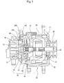
- Figure 1 is a cross sectional view illustrating the construction of an alternator in a conventional art;
- Figure 2 is a cross sectional illustrating a conventional output terminal assembly;
- Figure 3 is a disassembled cross sectional view illustrating an output terminal assembly according to an embodiment of the present invention;
- Figure 4 is a cross sectional view illustrating an assembled state of an output terminal assembly according to the present invention; and
- Figure 5 is a cross sectional view illustrating an output terminal assembly for a vehicle according to another embodiment of the present invention.
- The construction and operation of the present invention will be described with reference to the accompanying drawings.
- Figure 3 is a disassembled cross sectional view illustrating an output terminal assembly according to an embodiment of the present invention, and Figure 4 is a cross sectional view illustrating an assembled state of an output terminal assembly according to the present invention.
- As shown in Figure 1, the alternator includes a
casing 30 formed of arear bracket 10 and afront bracket 20, arotor 70 fixed to ashaft 60 in the interior of the casing, astator 50 fixed to an inner wall surface of the casing, abrush assembly 80, arectifier assembly 90, aheat sink 91, and aregulator 92. - The
output terminal 100 engaged with theheat 91 provided in the inner side of therear bracket 10 for outputting power to the outside includes an axialdirection output terminal 110, and a radiusdirection output terminal 120. - Here, the axial
direction output terminal 110 includes ahead part 111, anextension part 112, abody part 113, and athread part 115 formed at one end of the same. The radiusdirection output terminal 120 includes anexposure part 121, anassembling hole 123 provided in the inner side of theexposure part 121 and formed in a large size for thereby inserting theextension part 112, and aninsulation mold 112 that surrounds the above elements. - When assembling the above elements, the
extension part 112 of the axialdirection output terminal 110 is inserted into the assemblinghole 123 of the radiusdirection output terminal 120, and thethread part 115 of the axialdirection output terminal 110 is inserted from the outer side of therear bracket 10 to the inner direction of therear bracket 10 for thereby being fixed by anut 116. - At this time, the axial
direction output terminal 110 includes theextension part 112 of the lower side of the head part, and abody part 113. In addition, the axialdirection output terminal 110 further includes a heatsink contact part 114 at an intermediate portion. - The diameter D1 of the
extension part 112 and the diameter D2 of the heatsink contact part 114 are D2/D1 ≥ 0.70. - Namely, the diameter of the
extension part 112 is larger than the diameter of the heatsink contact part 114. - The
rear bracket 10 has an assemblingguide surface 10a in one side, and theexposure part 121 of the radiusdirection output terminal 120 contacts with the assemblingguide surface 10a. - Therefore, a uniform assembling direction is achieved in the radius
direction output terminal 120. - In the present invention, as shown in Figure 5, the
insulation mold 122 could be implemented in another method. - The
output terminal 100 includes an axialdirection output terminal 110 engaged with aheat sink 91 provided in the inner side of therear bracket 10 for outputting power to the outside, and a radiusdirection output terminal 120. Here, the axialdirection output terminal 110 includes ahead part 111, anextension part 112, abody part 113, and athread part 115 formed at one end. In addition, the radiusdirection output terminal 120 includes anexposure part 121 of an outer end, and anassembling hole 123 that is formed at an inner end of the opposite side for thereby inserting theextension part 112 thereinto. - In a state that the
extension part 112 of the axialdirection output terminal 110 is inserted into theassembling hole 123 of the radiusdirection output terminal 120, theinsulation mold 122 surrounds the body part of the radiusdirection output terminal 120 and thehead part 111 of the axialdirection output terminal 110. - The
thread part 115 of the axialdirection output terminal 110 is inserted from the outer side of therear bracket 10 to the inner side of therear bracket 10 for thereby being fixed using anut 116. - In the present invention, it is not needed to provide a cap on the axial
direction output terminal 110 like in the conventional art. - In the present invention, since the axial
direction output terminal 110 and theradius output terminal 120 are first assembled, an over force is not provided when assembling the radiusdirection output terminal 120 to the axialdirection output terminal 110. - In addition, since the axial
direction output terminal 110 is inserted from the outer side of therear bracket 10 to the inner direction of therear bracket 10, the assembling of the output terminal is finished before therear bracket 10 is assembled to the alternator. - As described above, in the present invention, since the head part of the axial direction output terminal is provided outside the rear bracket, it is possible to increase the contact area with respect to the radius direction output terminal without making the terminal hole of the heat sink larger.
- In addition, the radius direction output terminal is assembled with the axial direction output terminal before they are assembled with the bracket. Therefore, it is possible to assembly without a tight insertion, so that the insulation mold is not damaged.
- When assembling the radius direction output terminal, since an assembling guide surface is formed on an outer surface of the bracket, the radius direction output terminal is always assembled in one direction for thereby enhancing an assembling performance.
- In addition, as shown in Figure 5, since the insulation mold is covered in a state that the axial direction output terminal and the radius direction output terminal are assembled, two parts may be integrated to one part. Therefore, an easier handling and assembling productivity are enhanced. Since it is possible to prevent moisture and foreign substances from being inserted into the terminal contact parts, the life span of the output terminal assembly could be extended.
- As the present invention may be embodied in several forms without departing from the spirit or essential characteristics thereof, it should also be understood that the above-described examples are not limited by any of the details of the foregoing description, unless otherwise specified, but rather should be construed broadly within its spirit and scope as defined in the appended claims, and therefore all changes and modifications that fall within the meets and bounds of the claims, or equivalences of such meets and bounds are therefore intended to be embraced by the appended claims.
Claims (4)
- An alternator that includes a casing formed of a rear bracket and a front bracket, a rotor fixed to the shaft in the interior of the casing, a stator fixed to an inner wall surface of the casing, a brush assembly, a rectifier assembly, a heat sink and a regulator, an output terminal assembly of an alternator for a vehicle, comprising:an output terminal that includes an axial direction terminal engaged to the heat sink provided in an inner side of the rear bracket for outputting power to the outside, and a radius direction output terminal,wherein said axial direction output terminal includes a head part, an extension part, a body part, and a thread part formed at one end, and said radius direction output terminal includes an exposure part of an outer side end, an assembling hole formed at an inner end of the opposite side, and an insulation mold that covers the above elements; andwherein the extension part of the axial direction output terminal is inserted into an assembling hole of the radius direction output terminal, and the thread part of the axial direction output terminal is inserted from the outer side of the rear bracket to the inner side of the rear bracket for thereby being fixed using a nut.
- The assembly of claim 1, wherein said axial direction output terminal includes a heat sink contact part at an intermediate portion of the extension part in a lower side of the head part and the body part, and the diameter D1 of the extension part and the diameter D2 of the heat sink contact part are D2/D1 ≥ 0.70.
- The assembly of claim 1, wherein said rear bracket includes an assembling guide surface so that the exposure part of the radius direction output terminal is assembled with a certain direction.
- An alternator that includes a casing formed of a rear bracket and a front bracket, a rotor fixed to the shaft in the interior of the casing, a stator fixed to an inner wall surface of the casing, a brush assembly, a rectifier assembly, a heat sink and a regulator, an output terminal assembly of an alternator for a vehicle, comprising:an output terminal that includes an axial direction terminal engaged to the heat sink provided in an inner side of the rear bracket for outputting power to the outside, and a radius direction output terminal,wherein said axial direction output terminal includes a head part, an extension part, a body part, and a thread part at one end, and said radius direction output terminal includes an exposure part at an outer end, and an assembling hole substantially larger for inserting the extension part at an inner end of the opposite side; andwherein a body part of the radius direction output terminal and the head part of the axial direction output terminal are covered by an insulation mold in a state that the extension part of the axial direction terminal is inserted into the assembling hole of the radius direction output terminal; andwherein the thread part of the axial direction output terminal is inserted from the outer side of the rear bracket to the inner side of the rear bracket for thereby being fixed using a nut.
Applications Claiming Priority (1)
| Application Number | Priority Date | Filing Date | Title |
|---|---|---|---|
| KR1020040052203A KR100600557B1 (en) | 2004-07-06 | 2004-07-06 | Output terminal structure of vehicle generator |
Publications (2)
| Publication Number | Publication Date |
|---|---|
| EP1624548A2 true EP1624548A2 (en) | 2006-02-08 |
| EP1624548A3 EP1624548A3 (en) | 2006-03-22 |
Family
ID=35457896
Family Applications (1)
| Application Number | Title | Priority Date | Filing Date |
|---|---|---|---|
| EP04021483A Withdrawn EP1624548A3 (en) | 2004-07-06 | 2004-09-09 | Output terminal assembly of alternator for vehicle |
Country Status (4)
| Country | Link |
|---|---|
| EP (1) | EP1624548A3 (en) |
| JP (1) | JP3845433B2 (en) |
| KR (1) | KR100600557B1 (en) |
| CN (1) | CN100414818C (en) |
Cited By (4)
| Publication number | Priority date | Publication date | Assignee | Title |
|---|---|---|---|---|
| US7872385B2 (en) | 2007-07-27 | 2011-01-18 | GM Global Technology Operations LLC | Electric motor power connection assembly |
| FR2967828A1 (en) * | 2010-11-22 | 2012-05-25 | Valeo Equip Electr Moteur | TERMINAL FOR CONNECTION BETWEEN A ROTATING ELECTRIC MACHINE OF A MOTOR VEHICLE AND A CABLE OF THE ELECTRIC CIRCUIT OF THE VEHICLE |
| WO2012152491A1 (en) * | 2011-05-09 | 2012-11-15 | Zf Friedrichshafen Ag | Cable connecting device, and cable connector |
| CN108964379A (en) * | 2018-08-25 | 2018-12-07 | 中船重工电机科技股份有限公司 | Large Rotor enters shell tooling and enters shell side method |
Families Citing this family (1)
| Publication number | Priority date | Publication date | Assignee | Title |
|---|---|---|---|---|
| US8723380B2 (en) * | 2012-01-03 | 2014-05-13 | Remy Technologies, L.L.C. | Starter motor including a conductor mounting element |
Family Cites Families (3)
| Publication number | Priority date | Publication date | Assignee | Title |
|---|---|---|---|---|
| JPH06178494A (en) * | 1992-12-02 | 1994-06-24 | Hitachi Ltd | AC generator for automobile |
| KR0121641Y1 (en) * | 1995-04-19 | 1999-02-01 | 박기영 | Battery terminal assembly of alternator |
| EP1367694A1 (en) * | 2002-05-28 | 2003-12-03 | Valeo Mando Electrical Systems Korea Limited | Terminal for vehicle alternator |
-
2004
- 2004-07-06 KR KR1020040052203A patent/KR100600557B1/en not_active Expired - Fee Related
- 2004-09-03 JP JP2004256464A patent/JP3845433B2/en not_active Expired - Fee Related
- 2004-09-09 EP EP04021483A patent/EP1624548A3/en not_active Withdrawn
- 2004-10-21 CN CNB2004100860841A patent/CN100414818C/en not_active Expired - Fee Related
Cited By (6)
| Publication number | Priority date | Publication date | Assignee | Title |
|---|---|---|---|---|
| US7872385B2 (en) | 2007-07-27 | 2011-01-18 | GM Global Technology Operations LLC | Electric motor power connection assembly |
| FR2967828A1 (en) * | 2010-11-22 | 2012-05-25 | Valeo Equip Electr Moteur | TERMINAL FOR CONNECTION BETWEEN A ROTATING ELECTRIC MACHINE OF A MOTOR VEHICLE AND A CABLE OF THE ELECTRIC CIRCUIT OF THE VEHICLE |
| EP2456014A3 (en) * | 2010-11-22 | 2012-11-14 | Valeo Equipements Electriques Moteur | Connection terminal between a rotating electric machine of an automobile and a cable of the electric circuit of said vehicle |
| WO2012152491A1 (en) * | 2011-05-09 | 2012-11-15 | Zf Friedrichshafen Ag | Cable connecting device, and cable connector |
| CN108964379A (en) * | 2018-08-25 | 2018-12-07 | 中船重工电机科技股份有限公司 | Large Rotor enters shell tooling and enters shell side method |
| CN108964379B (en) * | 2018-08-25 | 2023-10-13 | 中船重工电机科技股份有限公司 | Large-scale motor rotor shell-entering tool and shell-entering method |
Also Published As
| Publication number | Publication date |
|---|---|
| JP2006025585A (en) | 2006-01-26 |
| EP1624548A3 (en) | 2006-03-22 |
| CN100414818C (en) | 2008-08-27 |
| KR20060003989A (en) | 2006-01-12 |
| JP3845433B2 (en) | 2006-11-15 |
| KR100600557B1 (en) | 2006-07-13 |
| CN1719698A (en) | 2006-01-11 |
Similar Documents
| Publication | Publication Date | Title |
|---|---|---|
| US8398384B2 (en) | Low-noise rotary pump having a press-fit stator using split-core ribs and housing ribs | |
| US7977846B2 (en) | Rotor for vehicular alternating current generator | |
| US6817459B1 (en) | Direct method of terminating the ground coil terminal to coil housing | |
| KR100983929B1 (en) | Connection structure of field coil and lead wire of automotive alternator, and connection method | |
| US20020140314A1 (en) | AC generator having air port in slip ring cover | |
| JP3661655B2 (en) | Brush support jig used for assembly of brush assembly of rotating electric machine and assembly method of brush assembly using the same | |
| EP1437770B1 (en) | Rectifying device having press-fitted member | |
| JPWO2014103056A1 (en) | Electric motor, pump, and method of manufacturing electric motor | |
| US6958557B2 (en) | Vehicle ac generator | |
| CN1666400A (en) | Motor | |
| JP5298918B2 (en) | Mold electric motor | |
| KR100600557B1 (en) | Output terminal structure of vehicle generator | |
| JP2011147227A (en) | Motor with reduction gear, and manufacturing method therefor | |
| JP3511948B2 (en) | Method for manufacturing vehicle alternator and stator used therein | |
| JP2009018417A (en) | Press-in method of press-fitting material | |
| KR100505272B1 (en) | Alternator equipped with insulation mean for coil of stator | |
| KR20070084528A (en) | Commutator's manufacturing method and commutator | |
| JP2007129890A (en) | Brush device for rotating electrical machine for vehicle | |
| CN100385772C (en) | Vehicle AC generator | |
| US20070103012A1 (en) | Method of manufacturing terminal assembly of alternator for vehicles and terminal assembly manufactured by the method | |
| JP4395141B2 (en) | Motor housing fixing structure | |
| EP1367694A1 (en) | Terminal for vehicle alternator | |
| JP2011502460A (en) | Method of manufacturing commutator ring for cylindrical commutator of electrical equipment, and electrical equipment | |
| CN107425658A (en) | Electric rotating machine | |
| KR100538408B1 (en) | Output terminal structure of alternator for vehicle |
Legal Events
| Date | Code | Title | Description |
|---|---|---|---|
| PUAI | Public reference made under article 153(3) epc to a published international application that has entered the european phase |
Free format text: ORIGINAL CODE: 0009012 |
|
| PUAL | Search report despatched |
Free format text: ORIGINAL CODE: 0009013 |
|
| AK | Designated contracting states |
Kind code of ref document: A2 Designated state(s): AT BE BG CH CY CZ DE DK EE ES FI FR GB GR HU IE IT LI LU MC NL PL PT RO SE SI SK TR |
|
| AX | Request for extension of the european patent |
Extension state: AL HR LT LV MK |
|
| AK | Designated contracting states |
Kind code of ref document: A3 Designated state(s): AT BE BG CH CY CZ DE DK EE ES FI FR GB GR HU IE IT LI LU MC NL PL PT RO SE SI SK TR |
|
| AX | Request for extension of the european patent |
Extension state: AL HR LT LV MK |
|
| AKX | Designation fees paid | ||
| STAA | Information on the status of an ep patent application or granted ep patent |
Free format text: STATUS: THE APPLICATION IS DEEMED TO BE WITHDRAWN |
|
| 18D | Application deemed to be withdrawn |
Effective date: 20060923 |
|
| REG | Reference to a national code |
Ref country code: DE Ref legal event code: 8566 |