EP1624264A1 - Refrigeration apparatus with tubular element - Google Patents
Refrigeration apparatus with tubular element Download PDFInfo
- Publication number
- EP1624264A1 EP1624264A1 EP05107107A EP05107107A EP1624264A1 EP 1624264 A1 EP1624264 A1 EP 1624264A1 EP 05107107 A EP05107107 A EP 05107107A EP 05107107 A EP05107107 A EP 05107107A EP 1624264 A1 EP1624264 A1 EP 1624264A1
- Authority
- EP
- European Patent Office
- Prior art keywords
- door
- refrigeration apparatus
- cabinet
- seat
- tubular
- Prior art date
- Legal status (The legal status is an assumption and is not a legal conclusion. Google has not performed a legal analysis and makes no representation as to the accuracy of the status listed.)
- Granted
Links
Images


Classifications
-
- F—MECHANICAL ENGINEERING; LIGHTING; HEATING; WEAPONS; BLASTING
- F25—REFRIGERATION OR COOLING; COMBINED HEATING AND REFRIGERATION SYSTEMS; HEAT PUMP SYSTEMS; MANUFACTURE OR STORAGE OF ICE; LIQUEFACTION SOLIDIFICATION OF GASES
- F25D—REFRIGERATORS; COLD ROOMS; ICE-BOXES; COOLING OR FREEZING APPARATUS NOT OTHERWISE PROVIDED FOR
- F25D23/00—General constructional features
- F25D23/02—Doors; Covers
- F25D23/028—Details
Definitions
- the present invention relates to a refrigeration apparatus according to the preamble of claim 1.
- Refrigeration apparatus comprise a cabinet being suitable for containing one or more refrigeration cells. At least one door is present for closing the refrigeration cells; very often there is a door for each cell. The door is connected to the cabinet by means of hinges.
- Refrigeration apparatus include refrigerators for domestic use; the following description will refer to said apparatus, without the invention being strictly limited thereto.
- the cells are suitable for containing food; often there is a cell for fresh food and a cell for frozen food.
- Said tubular element may be, for instance, the sheath of an electric cable; said electric cable may be used, for instance, to supply power to a light source being mounted on the door and facing inward, i.e. directed toward the refrigeration cell.
- said tubular element may be, for instance, a pipe carrying a liquid; said pipe may be used, for instance, to supply a refrigerated water distributor being mounted on the door and facing outward.
- the present invention aims at providing a new and improved solution compared to the state of the art.
- the idea at the basis of the present invention is to keep the tubular element separated from the hinges.
- This solution provides more flexibility in positioning and designing both the hinges and the structure for inserting the tubular element.
- Fig. 1 shows a schematic sectional view of a domestic-use refrigerator according to the present invention, indicated as a whole with the reference number 1.
- Said refrigerator comprises a cabinet 2 being placed on a base 11; in the illustration, the cabinet walls are very thick to indicate the presence of a thick layer of thermo-insulating material; in general, the thickness of the insulating material depends on the type of cell (in practice, on the operating temperatures of the cell) and, of course, on the type of insulating material employed; this is a common feature being well known to those skilled in the art.
- Said refrigerator comprises two refrigeration cells, being indicated as a whole with the reference number 10; a cell 10A is used for fresh food and is located in the upper portion of the cabinet 2, and a cell 10B is used for frozen food and is located in the lower portion of the cabinet 2.
- Two doors are provided, being indicated as a whole with the reference number 3, for closing the refrigerating cells 10; in particular, there is an upper door 3A for the cell 10A and a lower door 3B for the cell 10B.
- the refrigerator 1 is fitted with a refrigerated water distributor, being indicated as a whole with the reference number 6, which is mounted on a door of the refrigerator; in the illustrated embodiment example, the distributor is mounted on the upper door 3A.
- the refrigerated water distributor of the refrigerator is connected to the public drinking water supply.
- the water arrives at the refrigerator 1 from the supply through a pipe; the figure only shows a short length of said pipe; the supply pipe is connected to the inlet of a first solenoid valve 12; the outlet of the solenoid valve 12 is connected to a pipe being indicated with the reference number 4.
- the connection of the distributor 6 to the supply is represented as a single tubular element (being both simple and effective, and therefore preferable); other embodiments of the present invention may however comprise a number of interconnected tubular elements.
- the pipe 4 starts from a cavity obtained in the lower portion of the cabinet 2 (also housing the solenoid valve 12) and then enters the rear wall of the cabinet 2, runs within the insulating material up to the top of the cabinet 2, enters the upper wall of the cabinet 2, runs within the insulating material, leaves the cabinet 2 and enters the door 3A; the pipe 4 then runs within the insulating material of the door 3A and reaches the distributor 6.
- the above-mentioned cavity is also used, for example, for housing the refrigerator compressor.
- the distributor 6 comprises a tank 61, which receives water through the pipe 4; the tank 61 is located within the refrigeration cell 10A, so that the water being present in said tank is refrigerated.
- the distributor 6 also comprises a duct 62, being connected to the tank 61 through a second solenoid valve 63, which is used for distributing refrigerated water to the user.
- a refrigerated water filter may be inserted downstream the tank 61 and upstream the valve 63.
- means for controlling the supply of water to the tank 61 and means for controlling the distribution of water through the duct 62 comprise the solenoid valves 12 and 63 and an electronic control system (not illustrated), and are generally known to those skilled in the art.
- the upper door 3A of the refrigerator according to the embodiment example of Fig. 1 has a recess 7 where the duct 62 comes out; the recess 7 is open outward and is used to receive, for example, a glass 8 (without the possibility of an effective rest), to be filled with water coming out from the duct 62.
- said recess is not deep and therefore does not extend inside the refrigeration cells; thus the recess 7 does not subtract volume from the refrigeration cells, and the door 3A keeps a (thinner) layer of thermo-insulating material even in the area of the recess 7.
- the refrigerator doors 3A and 3B are connected to the cabinet through hinges allowing the doors to be opened and closed by the user with a rotary movement about a vertical axis.
- the hinges are not shown in Fig. 1 for simplicity's sake; in the field of refrigeration apparatus, different types of hinges are commonly used, which are generally known to those skilled in the art.
- the refrigeration apparatus comprises a cabinet, at least one door and a tubular element being inserted into the cabinet on the one side and into the door on the other side; the door is connected to the cabinet through hinges, which allow it to rotate about an axis, and is fitted with an inner tubular seat allowing to insert the tubular element through a suitable mouth of said seat; said seat is substantially coaxial to the hinges; furthermore, the seat mouth is located on the door in a position being distant from the hinges.
- Fig. 2 uses the same reference numbers as Fig. 1 to indicate corresponding elements; in particular, the cabinet is indicated with 2, the door with 3, and the tubular element with 4; besides, one of the hinges is indicated as a whole with 5, the hinge axis with 50, the tubular seat (inside the door 3) with 31 and its mouth with 311.
- the door can rotate without been disturbed by the tubular element and without damaging the tubular element.
- the passage of the tubular element and the hinges can be both positioned and designed more freely, thereby achieving a proper optimization of the same.
- the tubular seat inside the door may have, for instance, a circular cross-section; alternately, the shape of the cross-section may also be, for example: triangular, square, hexagonal, octagonal, ....
- the tubular element may be a pipe for carrying a liquid, like in all embodiments illustrated in the drawings; in this case, the present invention turns out to be rather useful, in that such a pipe is quite rigid and therefore it is on one hand more subject to damage due to the rotary movement of the door, and on the other it is more capable of disturbing the rotary movement of the door.
- the tubular element may alternately be a sheath of an electric cable; in this case, the present invention is at any rate useful in that the sheath is subject to wear even though it is not extremely rigid.
- tubular elements may be provided; typically, said tubular elements will be adjacent to each other and inserted in the same seats.
- the door rotation axis corresponding to the axis of the hinges, is substantially vertical; the door can thus be opened with a limited effort.
- the mouth of the tubular seat is located on an edge of the door, preferably on the upper edge of the door - the examples of Fig. 2 and Fig. 3 adopt this solution; the door has therefore no cavities for the insertion of the tubular element, and the tubular element turns out to be well protected and not easily accessible to the user.
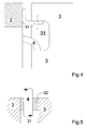
- the tubular element leaves the cabinet wall in the area corresponding to an insertion cavity 33 obtained on the door; the mouth of the tubular seat is located on the surface of said cavity. In this way, for instance, the tubular element is not required to reach the top of the refrigerator.
- the refrigerator hinges may be different to one another depending on their position; a hinge may comprise a first hinge element being fastened to the cabinet and a second hinge element being fastened to the door, mounted on the first hinge element and rotating about an axis, i.e. the hinge axis; in the examples of Fig. 2 and Fig. 3, the hinge element fastened to the cabinet 2 is indicated with 51, and the hinge element fastened to the door 3 is indicated with 52.
- a hinge element being indicated with 51, is fastened externally to the cabinet and is fitted with a pin (not shown in the illustration), and the other hinge element (also not shown) is fastened internally to the door and is mounted on said pin.
- the hinge elements consist of brackets.
- the hinge element fastened to the cabinet may be, for example, an "L" shaped bracket.
- This solution is used in the example of Fig. 2, which refers to the upper hinge being located in the area of the refrigerator top; in this way, the hinge does not protrude above the refrigerator top.
- the hinge element fastened to the door may be, for example, a "Z" shaped bracket.
- This solution is used in the example of Fig. 2, which refers to the upper hinge being located in the area of the refrigerator top; in this way, the hinge does not protrude from the refrigerator door. Brackets being shaped as described are very easy to mount.
- Fig. 3 shows an embodiment example of the upper hinge, being alternative to that of Fig. 2.
- one of the hinge elements may be advantageously fastened to an edge of the door, in order to facilitate the assembly; for the purposes of the present invention, i.e. when it is necessary to lay a tubular element between the cabinet and the door, the hinge element is preferably fastened to the upper edge of the door.
- the cabinet may be advantageously fitted with an inner tubular seat in order to insert the tubular element through a mouth of said seat on the cabinet.
- said tubular seat (within the cabinet 2) is indicated with 21 and its mouth with 211; in particular, in the example of Fig. 2 said seat is located in the middle of the thermo-insulating material of the cabinet, whereas in the example of Fig. 3 said seat is located on the outer surface of the cabinet.
- the cabinet inner tubular seat may advantageously be substantially perpendicular to the hinge axis; if the hinge axis is substantially vertical (as in most cases), the tubular seat will be substantially horizontal.
- This solution is shown in Fig. 2 and Fig. 3; in the example of Fig. 4, the tubular element runs within a side wall of the cabinet, and therefore the tubular seat may be either horizontal or sloping (as shown).
- An important feature of the present invention is the insertion of the tubular element into the tubular seats through suitable mouths of the latter, in particular as regards the door, being it movable.
- a bush being inserted into the mouth of the door tubular seat and having a hole for the insertion of the tubular element; this solution is shown in Fig. 5, wherein the bush is indicated with 32, the seat with 31 and the tubular element with 4; the bush can thus protect the tubular element from damage.
- the seat has preferably a circular inner cross-section and the bush has preferably a circular outer cross-section; also, these two diameters are nearly equal.
- the axis of the door tubular seat is substantially coaxial to the hinges.
- the hole of the bush is not perfectly coaxial to the bush axis (and therefore to the axis of the tubular seat); in fact, in this case the rigidity of the tubular element will prevent the bush from moving, so that any sliding can only occur between the bush and the tubular seat.
- the bush 32 is totally inserted into the tubular seat 31 of the door 3.
- the bush may also be fitted with a guide protruding from the mouth of the door tubular seat.
- FIG. 1 schematically shows the section of a domestic-use refrigerator having a refrigerated water distributor being connected to the public drinking water supply.
- the refrigerated beverage distributor is advantageously provided with a refrigerated beverage tank; in this case, a non-refrigerated beverage flows in the pipe.
- the refrigeration apparatus has a cell for fresh food being located in the upper portion of the cabinet and having its own door, and a cell for frozen food being located in the lower portion of the cabinet and having its own door, it is appropriate that the refrigerated beverage distributor is mounted on the door of the cell for fresh food.
Landscapes
- Engineering & Computer Science (AREA)
- Chemical & Material Sciences (AREA)
- Combustion & Propulsion (AREA)
- Physics & Mathematics (AREA)
- Mechanical Engineering (AREA)
- Thermal Sciences (AREA)
- General Engineering & Computer Science (AREA)
- Devices That Are Associated With Refrigeration Equipment (AREA)
- Refrigerator Housings (AREA)
- Shaping By String And By Release Of Stress In Plastics And The Like (AREA)
- Vaporization, Distillation, Condensation, Sublimation, And Cold Traps (AREA)
- Ceramic Capacitors (AREA)
Abstract
Description
- The present invention relates to a refrigeration apparatus according to the preamble of
claim 1. - Refrigeration apparatus comprise a cabinet being suitable for containing one or more refrigeration cells. At least one door is present for closing the refrigeration cells; very often there is a door for each cell. The door is connected to the cabinet by means of hinges.
- Refrigeration apparatus include refrigerators for domestic use; the following description will refer to said apparatus, without the invention being strictly limited thereto.
- As far as domestic-use refrigerators are concerned, the cells are suitable for containing food; often there is a cell for fresh food and a cell for frozen food.
- Domestic-use refrigerators, and more in general refrigeration apparatus, quite often require a tubular element being inserted into the cabinet on the one side and into the door on the other side.
- Said tubular element may be, for instance, the sheath of an electric cable; said electric cable may be used, for instance, to supply power to a light source being mounted on the door and facing inward, i.e. directed toward the refrigeration cell.
- Alternatively, said tubular element may be, for instance, a pipe carrying a liquid; said pipe may be used, for instance, to supply a refrigerated water distributor being mounted on the door and facing outward.
- It should be noted that distributor-fitted refrigerators have only recently begun to spread in Europe, whereas they have been used for decades in the USA. Actually, the European market demands products being rather different from those required by the American market, i.e. products being much less bulky (60 or 70 cm wide) and offering distribution of refrigerated water only, not of ice as well; moreover, said products must have a low cost and therefore must use simple but effective technical solutions.
- Of course, if there is a tubular element inserted between the cabinet and the door, being the door hinged to the cabinet and rotating, it is necessary to adopt a solution which allows the door to rotate without being disturbed by the tubular element and without damaging the tubular element.
- A solution dating back to the '30s, being suitable for electric cables, consisted in fastening the cable to the door on the one side and to the cabinet on the other side in positions being close to a hinge, where the relative motion between the door and the cabinet is limited; of course, this solution required a cable being long enough and flexible to follow the door movement. However, a frequent use of the door caused wear on the cable and especially on its sheath, thereby leading to a very dangerous exposure of the electric leads; this solution is hardly applicable to liquid carrying pipes due to their rigidity.
- The American Patent No. 2,148,787, granted in 1937, describes a refrigerator using said solution.
- In the '50s, it was thought of inserting the tubular element through the hinge; thus there is no substantial movement of the tubular element.
- Since then, this idea has been the basis of a lot of old and new solutions.
- As regards electric cables, we may indicate, for instance, the American Patents No. 2,700,139 of 1955, No. 3,076,163 of 1963, No. 3,089,202 of 1963, and No. 3,156,019 of 1964, whose solutions are based on said idea.
- As regards liquid carrying pipes, we may indicate the American Patent No. 3,429,140 of 1969, whose solution is based on said idea.
- There are also more recent solutions being based on said idea, which are described, for example, in the American Patents No. 4,036,620 of 1977, No. 4,543,800 of 1985 and No. 4,609,234 of 1986.
- New solutions based on said idea have been proposed even very recently, e.g. in the American Patent No. 5,941,619 of 1999 and in the European Patent No. 1139043 of 2001.
- It almost seems that this idea has become a standard.
- The present invention aims at providing a new and improved solution compared to the state of the art.
- This object is achieved by the refrigeration apparatus having the features described in
claim 1; advantageous aspects of the present invention are detailed in dependent claims. - The idea at the basis of the present invention is to keep the tubular element separated from the hinges.
- This solution provides more flexibility in positioning and designing both the hinges and the structure for inserting the tubular element.
- The present invention will become more apparent from the following description and from the annexed drawings, wherein:
- Fig. 1 shows a schematic sectional view of a refrigeration apparatus according to the present invention,
- Fig. 2 shows a schematic sectional view of a detail of a first embodiment example of a refrigeration apparatus according to the present invention,
- Fig. 3 shows a schematic sectional view of a detail of a second embodiment example of a refrigeration apparatus according to the present invention,
- Fig. 4 shows a schematic view of a detail of a third embodiment example of a refrigeration apparatus according to the present invention (in this figure, the door is fully open and the cabinet is sectioned), and
- Fig. 5 shows a schematic sectional view of the mouth area of a pipe seat according to the present invention.
- Both said description and said drawings are to be considered as non-limiting examples.
- Fig. 1 shows a schematic sectional view of a domestic-use refrigerator according to the present invention, indicated as a whole with the
reference number 1. - Said refrigerator comprises a
cabinet 2 being placed on abase 11; in the illustration, the cabinet walls are very thick to indicate the presence of a thick layer of thermo-insulating material; in general, the thickness of the insulating material depends on the type of cell (in practice, on the operating temperatures of the cell) and, of course, on the type of insulating material employed; this is a common feature being well known to those skilled in the art. - Said refrigerator comprises two refrigeration cells, being indicated as a whole with the reference number 10; a
cell 10A is used for fresh food and is located in the upper portion of thecabinet 2, and acell 10B is used for frozen food and is located in the lower portion of thecabinet 2. - Two doors are provided, being indicated as a whole with the
reference number 3, for closing the refrigerating cells 10; in particular, there is anupper door 3A for thecell 10A and alower door 3B for thecell 10B. - The
refrigerator 1 is fitted with a refrigerated water distributor, being indicated as a whole with thereference number 6, which is mounted on a door of the refrigerator; in the illustrated embodiment example, the distributor is mounted on theupper door 3A. - The refrigerated water distributor of the refrigerator according to the embodiment example of Fig. 1 is connected to the public drinking water supply. The water arrives at the
refrigerator 1 from the supply through a pipe; the figure only shows a short length of said pipe; the supply pipe is connected to the inlet of afirst solenoid valve 12; the outlet of thesolenoid valve 12 is connected to a pipe being indicated with thereference number 4. In the illustration, the connection of thedistributor 6 to the supply is represented as a single tubular element (being both simple and effective, and therefore preferable); other embodiments of the present invention may however comprise a number of interconnected tubular elements. - The
pipe 4 starts from a cavity obtained in the lower portion of the cabinet 2 (also housing the solenoid valve 12) and then enters the rear wall of thecabinet 2, runs within the insulating material up to the top of thecabinet 2, enters the upper wall of thecabinet 2, runs within the insulating material, leaves thecabinet 2 and enters thedoor 3A; thepipe 4 then runs within the insulating material of thedoor 3A and reaches thedistributor 6. - The above-mentioned cavity is also used, for example, for housing the refrigerator compressor.
- The
distributor 6 comprises atank 61, which receives water through thepipe 4; thetank 61 is located within therefrigeration cell 10A, so that the water being present in said tank is refrigerated. - The
distributor 6 also comprises aduct 62, being connected to thetank 61 through asecond solenoid valve 63, which is used for distributing refrigerated water to the user. - A refrigerated water filter may be inserted downstream the
tank 61 and upstream thevalve 63. Of course, it is necessary to employ means for controlling the supply of water to thetank 61 and means for controlling the distribution of water through theduct 62; these means comprise thesolenoid valves - The
upper door 3A of the refrigerator according to the embodiment example of Fig. 1 has arecess 7 where theduct 62 comes out; therecess 7 is open outward and is used to receive, for example, a glass 8 (without the possibility of an effective rest), to be filled with water coming out from theduct 62. - In the example of Fig. 1, said recess is not deep and therefore does not extend inside the refrigeration cells; thus the
recess 7 does not subtract volume from the refrigeration cells, and thedoor 3A keeps a (thinner) layer of thermo-insulating material even in the area of therecess 7. - The
refrigerator doors - In general, according to the present invention, the refrigeration apparatus comprises a cabinet, at least one door and a tubular element being inserted into the cabinet on the one side and into the door on the other side; the door is connected to the cabinet through hinges, which allow it to rotate about an axis, and is fitted with an inner tubular seat allowing to insert the tubular element through a suitable mouth of said seat; said seat is substantially coaxial to the hinges; furthermore, the seat mouth is located on the door in a position being distant from the hinges.
- Fig. 2 uses the same reference numbers as Fig. 1 to indicate corresponding elements; in particular, the cabinet is indicated with 2, the door with 3, and the tubular element with 4; besides, one of the hinges is indicated as a whole with 5, the hinge axis with 50, the tubular seat (inside the door 3) with 31 and its mouth with 311.
- Thanks to the above-specified solution, in particular to the substantial coaxiality achieved, the door can rotate without been disturbed by the tubular element and without damaging the tubular element.
- Furthermore, being the passage of the tubular element independent from the structure of the hinges, the passage of the tubular element and the hinges can be both positioned and designed more freely, thereby achieving a proper optimization of the same.
- The above-specified solution is used by all of the embodiment examples of Fig. 2, Fig. 3 and
- Fig. 4; said figures use the same reference numbers to indicate corresponding elements.
- The tubular seat inside the door may have, for instance, a circular cross-section; alternately, the shape of the cross-section may also be, for example: triangular, square, hexagonal, octagonal, ....
- The tubular element may be a pipe for carrying a liquid, like in all embodiments illustrated in the drawings; in this case, the present invention turns out to be rather useful, in that such a pipe is quite rigid and therefore it is on one hand more subject to damage due to the rotary movement of the door, and on the other it is more capable of disturbing the rotary movement of the door.
- Such a case finds a typical application in refrigerators being fitted with refrigerated water distributors, wherein a damaged pipe may cause at first water leaks from the pipe itself and then a failure of the distributor.
- The tubular element may alternately be a sheath of an electric cable; in this case, the present invention is at any rate useful in that the sheath is subject to wear even though it is not extremely rigid.
- This case finds many practical applications in refrigerators wherein a damaged sheath may cause short circuits or, even worse, electric shocks to the users.
- Very often, in refrigerators being fitted with a refrigerated water distributor it is necessary to supply water as well as electric power to the distributor, as for example in the refrigerator of Fig. 1, which requires electric power to energize the
solenoid valve 63. - In this case, still according to the present invention, two or more tubular elements may be provided; typically, said tubular elements will be adjacent to each other and inserted in the same seats.
- Alternately, there may be a single tubular element consisting of a sheath being suitable for containing a liquid-carrying pipe and one or more electric cables.
- Typically the door rotation axis, corresponding to the axis of the hinges, is substantially vertical; the door can thus be opened with a limited effort.
- According to a preferred embodiment of the present invention, the mouth of the tubular seat is located on an edge of the door, preferably on the upper edge of the door - the examples of Fig. 2 and Fig. 3 adopt this solution; the door has therefore no cavities for the insertion of the tubular element, and the tubular element turns out to be well protected and not easily accessible to the user.
- In the example of Fig. 4, the tubular element leaves the cabinet wall in the area corresponding to an
insertion cavity 33 obtained on the door; the mouth of the tubular seat is located on the surface of said cavity. In this way, for instance, the tubular element is not required to reach the top of the refrigerator. - The refrigerator hinges may be different to one another depending on their position; a hinge may comprise a first hinge element being fastened to the cabinet and a second hinge element being fastened to the door, mounted on the first hinge element and rotating about an axis, i.e. the hinge axis; in the examples of Fig. 2 and Fig. 3, the hinge element fastened to the
cabinet 2 is indicated with 51, and the hinge element fastened to thedoor 3 is indicated with 52. - In the examples of Fig. 2 and Fig. 3, the two hinge elements are pivoted to each other through a
pin 53; in the example of Fig. 4, a hinge element, being indicated with 51, is fastened externally to the cabinet and is fitted with a pin (not shown in the illustration), and the other hinge element (also not shown) is fastened internally to the door and is mounted on said pin. - According to preferred embodiment examples of the present invention (Fig. 2 and Fig. 3), the hinge elements consist of brackets.
- The hinge element fastened to the cabinet may be, for example, an "L" shaped bracket. This solution is used in the example of Fig. 2, which refers to the upper hinge being located in the area of the refrigerator top; in this way, the hinge does not protrude above the refrigerator top.
- The hinge element fastened to the door may be, for example, a "Z" shaped bracket. This solution is used in the example of Fig. 2, which refers to the upper hinge being located in the area of the refrigerator top; in this way, the hinge does not protrude from the refrigerator door. Brackets being shaped as described are very easy to mount.
- Fig. 3 shows an embodiment example of the upper hinge, being alternative to that of Fig. 2.
- In general, one of the hinge elements may be advantageously fastened to an edge of the door, in order to facilitate the assembly; for the purposes of the present invention, i.e. when it is necessary to lay a tubular element between the cabinet and the door, the hinge element is preferably fastened to the upper edge of the door.
- The cabinet may be advantageously fitted with an inner tubular seat in order to insert the tubular element through a mouth of said seat on the cabinet. All of the embodiment examples illustrated in the annexed drawings use this solution - in Fig. 2 and Fig. 3, said tubular seat (within the cabinet 2) is indicated with 21 and its mouth with 211; in particular, in the example of Fig. 2 said seat is located in the middle of the thermo-insulating material of the cabinet, whereas in the example of Fig. 3 said seat is located on the outer surface of the cabinet.
- In order to limit the space occupied by the tubular element in the cabinet, the cabinet inner tubular seat may advantageously be substantially perpendicular to the hinge axis; if the hinge axis is substantially vertical (as in most cases), the tubular seat will be substantially horizontal. This solution is shown in Fig. 2 and Fig. 3; in the example of Fig. 4, the tubular element runs within a side wall of the cabinet, and therefore the tubular seat may be either horizontal or sloping (as shown).
- In order that the tubular element is distant from one of the refrigerator hinges (the one being closer), it is advantageous to provide that said hinge element being fastened to the door defines a distance between said hinge element being fastened to the cabinet and the door edge. This solution is used in the examples of Fig. 2 and Fig. 3, wherein the edge of the
door 3 is kept distant from theelement 51 thanks to the shape of theelement 52; in the example of Fig. 4, the distance (between the hinge element being fastened to thecabinet 2 and the mouth of the tubular element in the door 3) is achieved thanks to the structure of thedoor 3, in particular to thecavity 33. - When the above-described solution is used, it may also be advantageous to locate the mouth of the cabinet tubular seat on the cabinet between the hinge element and the door edge. This solution is used in the examples of Fig. 2 and Fig. 3, wherein the
mouth 211 is located between the edge of thedoor 3 and theelement 51. - An important feature of the present invention is the insertion of the tubular element into the tubular seats through suitable mouths of the latter, in particular as regards the door, being it movable.
- On this matter, it may be advantageous to provide a bush being inserted into the mouth of the door tubular seat and having a hole for the insertion of the tubular element; this solution is shown in Fig. 5, wherein the bush is indicated with 32, the seat with 31 and the tubular element with 4; the bush can thus protect the tubular element from damage.
- If the bush is allowed to rotate within the door tubular seat, sliding will tend to occur between the bush and the seat and not between the tubular element and the bush. In this case, the seat has preferably a circular inner cross-section and the bush has preferably a circular outer cross-section; also, these two diameters are nearly equal.
- According to the present invention, the axis of the door tubular seat is substantially coaxial to the hinges.
- It may however be advantageous that the hole of the bush is not perfectly coaxial to the bush axis (and therefore to the axis of the tubular seat); in fact, in this case the rigidity of the tubular element will prevent the bush from moving, so that any sliding can only occur between the bush and the tubular seat.
- In the example of Fig. 5, the
bush 32 is totally inserted into thetubular seat 31 of thedoor 3. The bush may also be fitted with a guide protruding from the mouth of the door tubular seat. - Of course, further elements may also advantageously be provided for protecting the tubular element against access by the user in the area where it is neither inserted in the door nor in the cabinet.
- As already mentioned, the above-described solutions may clearly be advantageously applied to refrigeration apparatus, in particular to refrigeration apparatus being fitted with a refrigerated beverage distributor being mounted on the door and supplied through a tubular element.
- In this regard, Fig. 1 schematically shows the section of a domestic-use refrigerator having a refrigerated water distributor being connected to the public drinking water supply.
- The refrigerated beverage distributor is advantageously provided with a refrigerated beverage tank; in this case, a non-refrigerated beverage flows in the pipe.
- If the refrigeration apparatus has a cell for fresh food being located in the upper portion of the cabinet and having its own door, and a cell for frozen food being located in the lower portion of the cabinet and having its own door, it is appropriate that the refrigerated beverage distributor is mounted on the door of the cell for fresh food.
Claims (19)
- Refrigeration apparatus (1) comprising a cabinet (2), at least one door (3) and a tubular element (4) being inserted into the cabinet (2) on the one side and into the door (3) on the other side; the door (3) being connected to the cabinet through hinges (5), which allow it to rotate about an axis (50), and being fitted with an inner tubular seat (31) allowing to insert the tubular element (4) through a mouth (311) of said seat, said seat (31) being substantially coaxial to the hinges (5),
characterized in that
the mouth (311) of said seat (31) is located on the door (3) in a position being distant from the hinges (5). - Refrigeration apparatus (1) according to claim 1, wherein said axis (50) is substantially vertical.
- Refrigeration apparatus (1) according to claim 1 or 2, wherein the mouth (311) of the seat (31) is located on an edge of the door (3), preferably on the upper edge of the door (3).
- Refrigeration apparatus (1) according to claim 1 or 2 or 3, wherein at least one (5) of said hinges comprises a first hinge element (51) being fastened to the cabinet (2) and a second hinge element (52) being fastened to the door (3), mounted on the first hinge element (51) and rotating about said axis (50).
- Refrigeration apparatus (1) according to claim 4, wherein said first hinge element (51) is a bracket.
- Refrigeration apparatus (1) according to claim 4 or 5, wherein said second hinge element (52) is a bracket.
- Refrigeration apparatus (1) according to claim 4 or 5 or 6, wherein said second hinge element (52) is fastened to an edge of the door (5), preferably to the upper edge of the door.
- Refrigeration apparatus (1) according to one of the previous claims, wherein the cabinet (2) is fitted with an inner tubular seat (21) for the insertion of the tubular element (4) through a mouth (211) of said seat on the cabinet (2), said seat (21) being preferably substantially perpendicular to said axis (50).
- Refrigeration apparatus (1) according to one of claims from 4 to 8, wherein said second hinge element (52) defines a distance between said first hinge element (51) and said edge of the door (3).
- Refrigeration apparatus (1) according to claims 8 and 9, wherein the mouth (211) of the tubular seat (21) of the cabinet (2) is located on the cabinet (2) between said first hinge element (51) and said edge of the door (3).
- Refrigeration apparatus (1) according to one of the previous claims, comprising a bush (32) being inserted into the mouth (311) of the tubular seat (31) of the door (3) and having a hole for the insertion of the tubular element (4).
- Refrigeration apparatus (1) according to claim 11, wherein the bush (32) can rotate within the tubular seat (31).
- Refrigeration apparatus (1) according to claim 11 or 12, wherein the hole of the bush (32) is not coaxial to the axis of the bush (32).
- Refrigeration apparatus (1) according to one of the previous claims, wherein the tubular element (4) is a pipe carrying a liquid.
- Refrigeration apparatus (1) according to one of the previous claims, wherein the tubular element (4) is a sheath of an electric cable.
- Refrigeration apparatus (1) according to one of the previous claims, wherein the tubular element (4) is a sheath being suitable for containing a pipe carrying a liquid and one or more electric cables.
- Refrigeration apparatus (1) according to one of the previous claims, comprising a refrigerated beverage distributor (6), preferably refrigerated water, being mounted on the door (3A) and supplied through said pipe (4).
- Refrigeration apparatus (1) according to claim 17, wherein the refrigerated beverage distributor (6) is fitted with a refrigerated beverage tank (61).
- Refrigeration apparatus (1) according to claim 17 or 18, comprising:- a cell for fresh food (10A) being located in the upper portion of the cabinet and having its own door (3A), and- a cell for frozen food (10B) being located in the lower portion of the cabinet and having its own door (3B);
wherein the refrigerated beverage distributor (6) is mounted on the door (3A) of the cell for fresh food (10A).
Priority Applications (2)
| Application Number | Priority Date | Filing Date | Title |
|---|---|---|---|
| PL05107107T PL1624264T3 (en) | 2004-08-03 | 2005-08-01 | Refrigeration apparatus with tubular element |
| SI200530023T SI1624264T1 (en) | 2004-08-03 | 2005-08-01 | Refrigeration apparatus with tubular element |
Applications Claiming Priority (1)
| Application Number | Priority Date | Filing Date | Title |
|---|---|---|---|
| IT000545A ITTO20040545A1 (en) | 2004-08-03 | 2004-08-03 | REFRIGERATION APPARATUS WITH TUBULAR ELEMENT |
Publications (2)
| Publication Number | Publication Date |
|---|---|
| EP1624264A1 true EP1624264A1 (en) | 2006-02-08 |
| EP1624264B1 EP1624264B1 (en) | 2007-03-21 |
Family
ID=35219663
Family Applications (1)
| Application Number | Title | Priority Date | Filing Date |
|---|---|---|---|
| EP05107107A Expired - Lifetime EP1624264B1 (en) | 2004-08-03 | 2005-08-01 | Refrigeration apparatus with tubular element |
Country Status (9)
| Country | Link |
|---|---|
| EP (1) | EP1624264B1 (en) |
| AT (1) | ATE357637T1 (en) |
| DE (1) | DE602005000737T2 (en) |
| ES (1) | ES2282977T3 (en) |
| IT (1) | ITTO20040545A1 (en) |
| PL (1) | PL1624264T3 (en) |
| PT (1) | PT1624264E (en) |
| RU (1) | RU2382296C2 (en) |
| SI (1) | SI1624264T1 (en) |
Cited By (3)
| Publication number | Priority date | Publication date | Assignee | Title |
|---|---|---|---|---|
| EP2058612A1 (en) * | 2007-11-08 | 2009-05-13 | FagorBrandt SAS | Water supply to a water dispenser installed in the door of a refrigerator appliance |
| EP2743435A1 (en) | 2012-12-11 | 2014-06-18 | Indesit Company S.p.A. | Refrigerating appliance with guiding element for a flexible tubular element |
| US9759476B2 (en) | 2013-09-02 | 2017-09-12 | Indesit Comppany S.p. A. | Refrigerating appliance with a passage for a flexible tubular element between cabinet and door |
Citations (4)
| Publication number | Priority date | Publication date | Assignee | Title |
|---|---|---|---|---|
| US4912942A (en) * | 1989-02-21 | 1990-04-03 | Whirlpool Corporation | Refrigerator cabinet and door construction |
| EP0597680A1 (en) * | 1992-11-12 | 1994-05-18 | General Electric Company | Refrigerator with door mounted dispenser supply mechanism |
| US5768905A (en) * | 1995-12-19 | 1998-06-23 | Samsung Electronics Co., Ltd. | Refrigerator having a water dispenser and a water sterilizer |
| US6434792B1 (en) * | 2000-01-31 | 2002-08-20 | Universal Metal Products, Inc. | Hinge |
Family Cites Families (1)
| Publication number | Priority date | Publication date | Assignee | Title |
|---|---|---|---|---|
| US6003734A (en) * | 1995-07-26 | 1999-12-21 | Samsung Electronics Co., Ltd. | Water dispenser of refrigerator |
-
2004
- 2004-08-03 IT IT000545A patent/ITTO20040545A1/en unknown
-
2005
- 2005-08-01 EP EP05107107A patent/EP1624264B1/en not_active Expired - Lifetime
- 2005-08-01 DE DE602005000737T patent/DE602005000737T2/en not_active Expired - Lifetime
- 2005-08-01 ES ES05107107T patent/ES2282977T3/en not_active Expired - Lifetime
- 2005-08-01 PL PL05107107T patent/PL1624264T3/en unknown
- 2005-08-01 AT AT05107107T patent/ATE357637T1/en not_active IP Right Cessation
- 2005-08-01 SI SI200530023T patent/SI1624264T1/en unknown
- 2005-08-01 PT PT05107107T patent/PT1624264E/en unknown
- 2005-08-02 RU RU2005124668/12A patent/RU2382296C2/en not_active IP Right Cessation
Patent Citations (4)
| Publication number | Priority date | Publication date | Assignee | Title |
|---|---|---|---|---|
| US4912942A (en) * | 1989-02-21 | 1990-04-03 | Whirlpool Corporation | Refrigerator cabinet and door construction |
| EP0597680A1 (en) * | 1992-11-12 | 1994-05-18 | General Electric Company | Refrigerator with door mounted dispenser supply mechanism |
| US5768905A (en) * | 1995-12-19 | 1998-06-23 | Samsung Electronics Co., Ltd. | Refrigerator having a water dispenser and a water sterilizer |
| US6434792B1 (en) * | 2000-01-31 | 2002-08-20 | Universal Metal Products, Inc. | Hinge |
Cited By (4)
| Publication number | Priority date | Publication date | Assignee | Title |
|---|---|---|---|---|
| EP2058612A1 (en) * | 2007-11-08 | 2009-05-13 | FagorBrandt SAS | Water supply to a water dispenser installed in the door of a refrigerator appliance |
| FR2923586A1 (en) * | 2007-11-08 | 2009-05-15 | Fagorbrandt Sas Soc Par Action | WATER SUPPLY OF A WATER DISPENSER PLACED IN A DOOR OF A REFRIGERATION APPARATUS |
| EP2743435A1 (en) | 2012-12-11 | 2014-06-18 | Indesit Company S.p.A. | Refrigerating appliance with guiding element for a flexible tubular element |
| US9759476B2 (en) | 2013-09-02 | 2017-09-12 | Indesit Comppany S.p. A. | Refrigerating appliance with a passage for a flexible tubular element between cabinet and door |
Also Published As
| Publication number | Publication date |
|---|---|
| SI1624264T1 (en) | 2007-08-31 |
| RU2005124668A (en) | 2007-02-10 |
| EP1624264B1 (en) | 2007-03-21 |
| PT1624264E (en) | 2007-06-05 |
| DE602005000737T2 (en) | 2007-12-06 |
| DE602005000737D1 (en) | 2007-05-03 |
| ES2282977T3 (en) | 2007-10-16 |
| PL1624264T3 (en) | 2007-08-31 |
| ATE357637T1 (en) | 2007-04-15 |
| RU2382296C2 (en) | 2010-02-20 |
| ITTO20040545A1 (en) | 2004-11-03 |
Similar Documents
| Publication | Publication Date | Title |
|---|---|---|
| US10168094B2 (en) | Refrigerator | |
| US7261815B2 (en) | Water filter for refrigerator water dispenser | |
| US11543173B2 (en) | Refrigerator | |
| EP2908075B1 (en) | Refrigerator | |
| US20100218543A1 (en) | Water introduction into fresh-food icemaker | |
| KR20050026740A (en) | Refrigerator with dispenser | |
| CN102401529A (en) | Refrigerator | |
| JPH06213557A (en) | Supply mechanism to dispenser means and refrigerator | |
| CN115325750B (en) | refrigerator | |
| EP2024697B1 (en) | Refrigerator | |
| EP1624264B1 (en) | Refrigeration apparatus with tubular element | |
| CN101535750B (en) | Refrigeration appliances with cold water dispensers | |
| AU2022298740B2 (en) | Refrigerator | |
| CA2715746C (en) | Refrigerator with treated water system | |
| KR101052784B1 (en) | Refrigerator | |
| KR20140075302A (en) | Refrigerator | |
| KR101758922B1 (en) | Refrigerator | |
| KR100568203B1 (en) | Refrigerator | |
| KR20260000601A (en) | Water bottle, and all-in-one module and refrigerator including the same | |
| KR102494120B1 (en) | Filter assembly and refrigerator including the same | |
| US20210033328A1 (en) | Refrigerator comprising an ice maker assembly | |
| KR0126434B1 (en) | Refrigeration prevention of refrigerator | |
| KR100488072B1 (en) | Door structure for refrigerator | |
| KR0119862Y1 (en) | Beverage supply device | |
| US20090044562A1 (en) | Door for a Refrigerator |
Legal Events
| Date | Code | Title | Description |
|---|---|---|---|
| PUAI | Public reference made under article 153(3) epc to a published international application that has entered the european phase |
Free format text: ORIGINAL CODE: 0009012 |
|
| AK | Designated contracting states |
Kind code of ref document: A1 Designated state(s): AT BE BG CH CY CZ DE DK EE ES FI FR GB GR HU IE IS IT LI LT LU LV MC NL PL PT RO SE SI SK TR |
|
| AX | Request for extension of the european patent |
Extension state: AL BA HR MK YU |
|
| 17P | Request for examination filed |
Effective date: 20060322 |
|
| GRAP | Despatch of communication of intention to grant a patent |
Free format text: ORIGINAL CODE: EPIDOSNIGR1 |
|
| AKX | Designation fees paid |
Designated state(s): AT BE BG CH CY CZ DE DK EE ES FI FR GB GR HU IE IS IT LI LT LU LV MC NL PL PT RO SE SI SK TR |
|
| GRAS | Grant fee paid |
Free format text: ORIGINAL CODE: EPIDOSNIGR3 |
|
| GRAA | (expected) grant |
Free format text: ORIGINAL CODE: 0009210 |
|
| AK | Designated contracting states |
Kind code of ref document: B1 Designated state(s): AT BE BG CH CY CZ DE DK EE ES FI FR GB GR HU IE IS IT LI LT LU LV MC NL PL PT RO SE SI SK TR |
|
| PG25 | Lapsed in a contracting state [announced via postgrant information from national office to epo] |
Ref country code: FI Free format text: LAPSE BECAUSE OF FAILURE TO SUBMIT A TRANSLATION OF THE DESCRIPTION OR TO PAY THE FEE WITHIN THE PRESCRIBED TIME-LIMIT Effective date: 20070321 Ref country code: NL Free format text: LAPSE BECAUSE OF FAILURE TO SUBMIT A TRANSLATION OF THE DESCRIPTION OR TO PAY THE FEE WITHIN THE PRESCRIBED TIME-LIMIT Effective date: 20070321 Ref country code: AT Free format text: LAPSE BECAUSE OF FAILURE TO SUBMIT A TRANSLATION OF THE DESCRIPTION OR TO PAY THE FEE WITHIN THE PRESCRIBED TIME-LIMIT Effective date: 20070321 Ref country code: LI Free format text: LAPSE BECAUSE OF FAILURE TO SUBMIT A TRANSLATION OF THE DESCRIPTION OR TO PAY THE FEE WITHIN THE PRESCRIBED TIME-LIMIT Effective date: 20070321 Ref country code: CH Free format text: LAPSE BECAUSE OF FAILURE TO SUBMIT A TRANSLATION OF THE DESCRIPTION OR TO PAY THE FEE WITHIN THE PRESCRIBED TIME-LIMIT Effective date: 20070321 Ref country code: BE Free format text: LAPSE BECAUSE OF FAILURE TO SUBMIT A TRANSLATION OF THE DESCRIPTION OR TO PAY THE FEE WITHIN THE PRESCRIBED TIME-LIMIT Effective date: 20070321 |
|
| REG | Reference to a national code |
Ref country code: GB Ref legal event code: FG4D |
|
| REG | Reference to a national code |
Ref country code: RO Ref legal event code: EPE |
|
| REG | Reference to a national code |
Ref country code: CH Ref legal event code: EP |
|
| REF | Corresponds to: |
Ref document number: 602005000737 Country of ref document: DE Date of ref document: 20070503 Kind code of ref document: P |
|
| REG | Reference to a national code |
Ref country code: IE Ref legal event code: FG4D |
|
| REG | Reference to a national code |
Ref country code: PT Ref legal event code: SC4A Free format text: AVAILABILITY OF NATIONAL TRANSLATION Effective date: 20070524 |
|
| REG | Reference to a national code |
Ref country code: SE Ref legal event code: TRGR |
|
| REG | Reference to a national code |
Ref country code: GR Ref legal event code: EP Ref document number: 20070401490 Country of ref document: GR |
|
| PG25 | Lapsed in a contracting state [announced via postgrant information from national office to epo] |
Ref country code: IS Free format text: LAPSE BECAUSE OF FAILURE TO SUBMIT A TRANSLATION OF THE DESCRIPTION OR TO PAY THE FEE WITHIN THE PRESCRIBED TIME-LIMIT Effective date: 20070721 |
|
| REG | Reference to a national code |
Ref country code: HU Ref legal event code: AG4A Ref document number: E001812 Country of ref document: HU |
|
| ET | Fr: translation filed | ||
| REG | Reference to a national code |
Ref country code: PL Ref legal event code: T3 |
|
| REG | Reference to a national code |
Ref country code: CH Ref legal event code: PL |
|
| NLV1 | Nl: lapsed or annulled due to failure to fulfill the requirements of art. 29p and 29m of the patents act | ||
| REG | Reference to a national code |
Ref country code: ES Ref legal event code: FG2A Ref document number: 2282977 Country of ref document: ES Kind code of ref document: T3 |
|
| PG25 | Lapsed in a contracting state [announced via postgrant information from national office to epo] |
Ref country code: SK Free format text: LAPSE BECAUSE OF FAILURE TO SUBMIT A TRANSLATION OF THE DESCRIPTION OR TO PAY THE FEE WITHIN THE PRESCRIBED TIME-LIMIT Effective date: 20070321 |
|
| PLBE | No opposition filed within time limit |
Free format text: ORIGINAL CODE: 0009261 |
|
| STAA | Information on the status of an ep patent application or granted ep patent |
Free format text: STATUS: NO OPPOSITION FILED WITHIN TIME LIMIT |
|
| PG25 | Lapsed in a contracting state [announced via postgrant information from national office to epo] |
Ref country code: DK Free format text: LAPSE BECAUSE OF FAILURE TO SUBMIT A TRANSLATION OF THE DESCRIPTION OR TO PAY THE FEE WITHIN THE PRESCRIBED TIME-LIMIT Effective date: 20070321 Ref country code: LV Free format text: LAPSE BECAUSE OF FAILURE TO SUBMIT A TRANSLATION OF THE DESCRIPTION OR TO PAY THE FEE WITHIN THE PRESCRIBED TIME-LIMIT Effective date: 20070321 |
|
| 26N | No opposition filed |
Effective date: 20071227 |
|
| PG25 | Lapsed in a contracting state [announced via postgrant information from national office to epo] |
Ref country code: MC Free format text: LAPSE BECAUSE OF NON-PAYMENT OF DUE FEES Effective date: 20070831 |
|
| PG25 | Lapsed in a contracting state [announced via postgrant information from national office to epo] |
Ref country code: IE Free format text: LAPSE BECAUSE OF NON-PAYMENT OF DUE FEES Effective date: 20070801 |
|
| PGFP | Annual fee paid to national office [announced via postgrant information from national office to epo] |
Ref country code: BG Payment date: 20080828 Year of fee payment: 4 Ref country code: PT Payment date: 20080723 Year of fee payment: 4 Ref country code: SI Payment date: 20080723 Year of fee payment: 4 |
|
| PGFP | Annual fee paid to national office [announced via postgrant information from national office to epo] |
Ref country code: RO Payment date: 20080804 Year of fee payment: 4 Ref country code: LT Payment date: 20080722 Year of fee payment: 4 |
|
| PG25 | Lapsed in a contracting state [announced via postgrant information from national office to epo] |
Ref country code: EE Free format text: LAPSE BECAUSE OF FAILURE TO SUBMIT A TRANSLATION OF THE DESCRIPTION OR TO PAY THE FEE WITHIN THE PRESCRIBED TIME-LIMIT Effective date: 20070321 |
|
| PGFP | Annual fee paid to national office [announced via postgrant information from national office to epo] |
Ref country code: HU Payment date: 20080810 Year of fee payment: 4 Ref country code: SE Payment date: 20080825 Year of fee payment: 4 |
|
| PG25 | Lapsed in a contracting state [announced via postgrant information from national office to epo] |
Ref country code: CY Free format text: LAPSE BECAUSE OF FAILURE TO SUBMIT A TRANSLATION OF THE DESCRIPTION OR TO PAY THE FEE WITHIN THE PRESCRIBED TIME-LIMIT Effective date: 20070321 |
|
| PG25 | Lapsed in a contracting state [announced via postgrant information from national office to epo] |
Ref country code: LU Free format text: LAPSE BECAUSE OF NON-PAYMENT OF DUE FEES Effective date: 20070801 |
|
| PGFP | Annual fee paid to national office [announced via postgrant information from national office to epo] |
Ref country code: ES Payment date: 20090826 Year of fee payment: 5 |
|
| PGFP | Annual fee paid to national office [announced via postgrant information from national office to epo] |
Ref country code: CZ Payment date: 20090731 Year of fee payment: 5 Ref country code: DE Payment date: 20090827 Year of fee payment: 5 Ref country code: GB Payment date: 20090826 Year of fee payment: 5 Ref country code: PL Payment date: 20090729 Year of fee payment: 5 Ref country code: TR Payment date: 20090803 Year of fee payment: 5 |
|
| REG | Reference to a national code |
Ref country code: PT Ref legal event code: MM4A Free format text: LAPSE DUE TO NON-PAYMENT OF FEES Effective date: 20100201 |
|
| LTLA | Lt: lapse of european patent or patent extension |
Effective date: 20090801 |
|
| PG25 | Lapsed in a contracting state [announced via postgrant information from national office to epo] |
Ref country code: PT Free format text: LAPSE BECAUSE OF NON-PAYMENT OF DUE FEES Effective date: 20100201 |
|
| REG | Reference to a national code |
Ref country code: SI Ref legal event code: KO00 Effective date: 20100304 |
|
| PG25 | Lapsed in a contracting state [announced via postgrant information from national office to epo] |
Ref country code: SI Free format text: LAPSE BECAUSE OF NON-PAYMENT OF DUE FEES Effective date: 20090802 |
|
| PG25 | Lapsed in a contracting state [announced via postgrant information from national office to epo] |
Ref country code: HU Free format text: LAPSE BECAUSE OF NON-PAYMENT OF DUE FEES Effective date: 20090802 Ref country code: RO Free format text: LAPSE BECAUSE OF NON-PAYMENT OF DUE FEES Effective date: 20090801 Ref country code: BG Free format text: LAPSE BECAUSE OF EXPIRATION OF PROTECTION Effective date: 20100228 |
|
| PG25 | Lapsed in a contracting state [announced via postgrant information from national office to epo] |
Ref country code: GR Free format text: LAPSE BECAUSE OF NON-PAYMENT OF DUE FEES Effective date: 20100303 |
|
| GBPC | Gb: european patent ceased through non-payment of renewal fee |
Effective date: 20100801 |
|
| REG | Reference to a national code |
Ref country code: FR Ref legal event code: ST Effective date: 20110502 |
|
| PG25 | Lapsed in a contracting state [announced via postgrant information from national office to epo] |
Ref country code: CZ Free format text: LAPSE BECAUSE OF NON-PAYMENT OF DUE FEES Effective date: 20100801 Ref country code: SE Free format text: LAPSE BECAUSE OF NON-PAYMENT OF DUE FEES Effective date: 20090802 |
|
| REG | Reference to a national code |
Ref country code: DE Ref legal event code: R119 Ref document number: 602005000737 Country of ref document: DE Effective date: 20110301 |
|
| PG25 | Lapsed in a contracting state [announced via postgrant information from national office to epo] |
Ref country code: FR Free format text: LAPSE BECAUSE OF NON-PAYMENT OF DUE FEES Effective date: 20100831 Ref country code: DE Free format text: LAPSE BECAUSE OF NON-PAYMENT OF DUE FEES Effective date: 20110301 |
|
| PG25 | Lapsed in a contracting state [announced via postgrant information from national office to epo] |
Ref country code: GB Free format text: LAPSE BECAUSE OF NON-PAYMENT OF DUE FEES Effective date: 20100801 |
|
| PGFP | Annual fee paid to national office [announced via postgrant information from national office to epo] |
Ref country code: FR Payment date: 20090909 Year of fee payment: 5 |
|
| REG | Reference to a national code |
Ref country code: ES Ref legal event code: FD2A Effective date: 20111019 |
|
| PG25 | Lapsed in a contracting state [announced via postgrant information from national office to epo] |
Ref country code: ES Free format text: LAPSE BECAUSE OF NON-PAYMENT OF DUE FEES Effective date: 20100802 |
|
| REG | Reference to a national code |
Ref country code: PL Ref legal event code: LAPE |
|
| PG25 | Lapsed in a contracting state [announced via postgrant information from national office to epo] |
Ref country code: PL Free format text: LAPSE BECAUSE OF NON-PAYMENT OF DUE FEES Effective date: 20100801 |
|
| PG25 | Lapsed in a contracting state [announced via postgrant information from national office to epo] |
Ref country code: TR Free format text: LAPSE BECAUSE OF NON-PAYMENT OF DUE FEES Effective date: 20100801 |
|
| PGFP | Annual fee paid to national office [announced via postgrant information from national office to epo] |
Ref country code: IT Payment date: 20160822 Year of fee payment: 12 |
|
| PG25 | Lapsed in a contracting state [announced via postgrant information from national office to epo] |
Ref country code: IT Free format text: LAPSE BECAUSE OF NON-PAYMENT OF DUE FEES Effective date: 20170801 |