EP1624227A2 - Ball screw device - Google Patents
Ball screw device Download PDFInfo
- Publication number
- EP1624227A2 EP1624227A2 EP05016978A EP05016978A EP1624227A2 EP 1624227 A2 EP1624227 A2 EP 1624227A2 EP 05016978 A EP05016978 A EP 05016978A EP 05016978 A EP05016978 A EP 05016978A EP 1624227 A2 EP1624227 A2 EP 1624227A2
- Authority
- EP
- European Patent Office
- Prior art keywords
- ball
- balls
- ball screw
- path
- nut
- Prior art date
- Legal status (The legal status is an assumption and is not a legal conclusion. Google has not performed a legal analysis and makes no representation as to the accuracy of the status listed.)
- Granted
Links
Images



Classifications
-
- F—MECHANICAL ENGINEERING; LIGHTING; HEATING; WEAPONS; BLASTING
- F16—ENGINEERING ELEMENTS AND UNITS; GENERAL MEASURES FOR PRODUCING AND MAINTAINING EFFECTIVE FUNCTIONING OF MACHINES OR INSTALLATIONS; THERMAL INSULATION IN GENERAL
- F16H—GEARING
- F16H25/00—Gearings comprising primarily only cams, cam-followers and screw-and-nut mechanisms
- F16H25/18—Gearings comprising primarily only cams, cam-followers and screw-and-nut mechanisms for conveying or interconverting oscillating or reciprocating motions
- F16H25/20—Screw mechanisms
- F16H25/22—Screw mechanisms with balls, rollers, or similar members between the co-operating parts; Elements essential to the use of such members
- F16H25/2204—Screw mechanisms with balls, rollers, or similar members between the co-operating parts; Elements essential to the use of such members with balls
- F16H25/2214—Screw mechanisms with balls, rollers, or similar members between the co-operating parts; Elements essential to the use of such members with balls with elements for guiding the circulating balls
-
- Y—GENERAL TAGGING OF NEW TECHNOLOGICAL DEVELOPMENTS; GENERAL TAGGING OF CROSS-SECTIONAL TECHNOLOGIES SPANNING OVER SEVERAL SECTIONS OF THE IPC; TECHNICAL SUBJECTS COVERED BY FORMER USPC CROSS-REFERENCE ART COLLECTIONS [XRACs] AND DIGESTS
- Y10—TECHNICAL SUBJECTS COVERED BY FORMER USPC
- Y10T—TECHNICAL SUBJECTS COVERED BY FORMER US CLASSIFICATION
- Y10T74/00—Machine element or mechanism
- Y10T74/19—Gearing
- Y10T74/19642—Directly cooperating gears
- Y10T74/19698—Spiral
- Y10T74/19702—Screw and nut
- Y10T74/19744—Rolling element engaging thread
- Y10T74/19749—Recirculating rolling elements
- Y10T74/19767—Return path geometry
-
- Y—GENERAL TAGGING OF NEW TECHNOLOGICAL DEVELOPMENTS; GENERAL TAGGING OF CROSS-SECTIONAL TECHNOLOGIES SPANNING OVER SEVERAL SECTIONS OF THE IPC; TECHNICAL SUBJECTS COVERED BY FORMER USPC CROSS-REFERENCE ART COLLECTIONS [XRACs] AND DIGESTS
- Y10—TECHNICAL SUBJECTS COVERED BY FORMER USPC
- Y10T—TECHNICAL SUBJECTS COVERED BY FORMER US CLASSIFICATION
- Y10T74/00—Machine element or mechanism
- Y10T74/19—Gearing
- Y10T74/19642—Directly cooperating gears
- Y10T74/19698—Spiral
- Y10T74/19702—Screw and nut
- Y10T74/19744—Rolling element engaging thread
- Y10T74/19749—Recirculating rolling elements
- Y10T74/19767—Return path geometry
- Y10T74/19772—Rolling element deflector
-
- Y—GENERAL TAGGING OF NEW TECHNOLOGICAL DEVELOPMENTS; GENERAL TAGGING OF CROSS-SECTIONAL TECHNOLOGIES SPANNING OVER SEVERAL SECTIONS OF THE IPC; TECHNICAL SUBJECTS COVERED BY FORMER USPC CROSS-REFERENCE ART COLLECTIONS [XRACs] AND DIGESTS
- Y10—TECHNICAL SUBJECTS COVERED BY FORMER USPC
- Y10T—TECHNICAL SUBJECTS COVERED BY FORMER US CLASSIFICATION
- Y10T74/00—Machine element or mechanism
- Y10T74/19—Gearing
- Y10T74/19642—Directly cooperating gears
- Y10T74/19698—Spiral
- Y10T74/19702—Screw and nut
- Y10T74/19744—Rolling element engaging thread
- Y10T74/19749—Recirculating rolling elements
- Y10T74/19777—Interconnected or cooperating rollers or roller structure
Definitions
- the present invention relates to a ball screw device for converting rotational motion into linear motion.
- a ball screw device of a tube circulation type as shown in FIG. 8 is used as a device for converting rotational motion into linear motion.
- the ball screw device comprises: a screw shaft 1; and a nut 2 having an inner periphery provided with a ball screw groove 4 opposing a ball screw groove 3 formed in the outer periphery of the screw shaft 1.
- a large number of balls 6 serving as rolling elements are arranged in a ball load rolling path 5 formed between the ball screw groove 3 and the ball screw groove 4. These balls 6 roll on between the ball screw grooves 3 and 4 in association with the revolution of the screw shaft 1 or the nut 2.
- a flat part 2a formed in the outer periphery of the nut 2 is provided with a ball circulating tube 7 for circulating the balls 6.
- the ball circulating tube 7 is fabricated by bending into a U-shape a tube material composed of metal.
- the flat part 2a of the nut 2 is provided with two circulating tube insertion holes 8 into each of which an end of the ball circulating tube 7 is inserted.
- the ball circulating tube 7 has a tongue section at each end, so that the balls 6 rolling on between the ball screw grooves 3 and 4 are scooped up from the ball screw grooves 3 and 4 by the tongue section of the ball circulating tube 7.
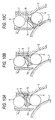
- the ball retaining piece 9 when the filling factor of the ball retainingpiecesbecomes small in theball circulation path, the ball retaining piece 9 can be temporarily caught at a step 10 or a gap 11 appearing near the outlet of the ball circulating tube 7 or alternatively at the tongue section 7a of the ball circulating tube 7, as shown in FIGS. 10A-10C. This causes trouble.
- the filling factor of the ball retaining pieces 9 need to be managed strictly at the time of fabrication. Alternatively, accuracy needs to be improved in the machining of the circulating tube insertion hole 8.
- An object of the invention is to provide a ball screw device free from the temporary catch of a ball retaining piece even when the filling factor of the ball retaining pieces is small in the ball circulation path.
- a first aspect of the invention is a ball screw device comprising: a screw shaft having an outer periphery provided with a ball screw groove; a nut having an inner periphery provided with a ball screw groove opposing the ball screw groove of the screw shaft; a large number of balls rolling on a ball load rolling path formed between the ball screw groove of said screw shaft and the ball screw groove of said nut, in association with revolution of said screw shaft or said nut; and a ball circulating member having a ball return path for circulating these balls, wherein resin-fabricated ball retaining pieces for suppressing jamming of said balls are respectively arranged between the balls, and wherein said ball circulating member is provided with a ball scooping section for scooping up the balls rolling on between said ball screw grooves, along a line tangent to a center orbital circle of the balls.
- a second aspect of the invention is a ball screw device according to the first aspect, wherein saidball scooping section has a line-shaped ball scooping path section in a boundary part between said ball load rolling path and said ball return path, and wherein said ball scooping path section has a path length of 1/2D or greater relative to a diameter D of said ball.
- a third aspect of the invention is a ball screw device comprising: a screw shaft having an outer periphery provided with a ball screw groove; a nut having an inner periphery provided with a ball screw groove opposing the ball screw groove of the screw shaft; a large number of balls rolling on a ball load rolling path formed between the ball screw groove of said screw shaft and the ball screw groove of said nut, in association with revolution of said screw shaft or said nut; and a ball circulating tube having a ball return path for circulating these balls, wherein resin-fabricated ball retaining pieces for suppressing jamming of saidballs are respectively arranged between the balls, and wherein a ball- scooping path formed in a boundary part between saidball load rolling path and said ball return path has a length of 1/2 or greater of a diameter of said ball.
- a ball circulating member is provided with a ball scooping section for scooping up the balls rolling on between the ball screw grooves, along a line tangent to the center orbital circle of the balls.
- the balls and the ball retaining pieces align almost linearly along the line tangent to the ball center orbital circle. Accordingly, in contrast to the case of the tube circulation type ball screw device, the orientation of the ball retaining piece does not largely change in the boundary part between the ball load rolling path and the ball return path. This avoids the temporary catch of the ball retaining piece even when the filling factor of the ball retaining pieces is small in the ball circulation path.
- the path length of the ball scoopingpath section is set to be 1/2D or greater relative to the diameter D of the ball. This avoids more reliably the temporary catch of the ball retainingpiece even when the filling factor of the ball retaining pieces is small in the ball circulation path.
- the length of the ball scooping path formed in the boundary part-between the ball load rolling path and the ball return path is set to be 1/2 or greater of the diameter of the ball.
- the discontinuous scooping section becomes distant from a portion where a step, a gap, or the like can arise. This avoids the temporary catch of the ball retaining piece even when the filling factor of the ball retaining pieces is small in the ball circulation path.
- FIGS. 1-5 show a ball screw device according to an embodiment of the invention.
- the ball screw device according to an embodiment of the invention comprises a screw shaft 1 and a nut 2.
- a ball screw groove 3 is formed in the outer periphery of the screw shaft 1.
- the ball screw groove 3 opposes a ball screw groove 4 (see FIG. 2) formed in the inner periphery of the nut 2.
- a large number of balls 6 serving as rolling elements are arranged in a ball load rolling path 5 (see FIG. 3) formed between the ball screw groove 3 and the ball screw groove 4.
- the balls 6 are arranged in line along the ball screw grooves 3 and 4.
- Ball retaining pieces 9 fabricated of resin for avoiding jamming of the balls are respectively provided between the balls 6. These balls 6 roll on the ball load rolling path 5 in association with the revolution of the screw shaft 1 or the nut 2.
- a flat part 2a formed in the outer periphery of the nut 2 is provided with a ball circulating member 12 fabricated of synthetic resin material.
- the ball circulating member 12 has a ball return path 13 (see FIG. 1) for circulating the balls 6 rolling on the ball load rolling path 5.
- the balls 6 having rolled through the ball load rolling path 5 are circulated through the ball return path 13 of the ball circulating member 12.
- the ball circulating member 12 comprises: a main body 14 having a fixing face 14a fixed to the flat part 2a of the nut 2; and columrx-shaped ball scooping sections 15 and 16 extending from the fixing face 14a of the main body 14 toward the flat part 2a of the nut 2.
- the flat part 2a of the nut 2 is provided with circulating member insertion holes 17 and 18 (see FIG. 2) fitted respectively with the ball scooping sections 15 and 16 of the ball circulating member 12.
- These circulating member insertion holes 17 and 18 are formed in the shape of an ellipse in the longitudinal direction of the ball screw groove 4 so as to avoid interference with the ball screw groove 4 formed in the inner periphery of the nut 2.
- a line-shaped ball scooping path section 19 for scooping up the balls 6 having rolled through the ball load rolling path 5, along a line S tangent to the center orbital circle BC of the balls 6 is provided in the boundary part between the ball load rolling path 5 and the ball return path 13.
- the ball scooping path section 19 has a path length L greater than or equal to 1/2D relative to the diameter D of the ball 6.
- the ball circulating member 12 is fixed to the flat part 2a of the nut 2 with two screws 20 (see FIG. 1).
- the flat part 2a of the nut 2 is provided with two tapped holes (not shown) into which the screws 20 are inserted.
- the ball circulating member 12 is constructed from a pair of resin molded members 21 (see FIG. 5) .
- Each resin molded member 21 is provided with a ball return path forming groove (not shown) for forming the ball return path 13.
- the ball circulating member 12 may be fixed to the nut 2 using a fixing component of the form of a metal cover.
- the ball scooping sections 15 and 16 for scooping up the balls 6 rolling on between the ball screw grooves 3 and 4, along the line S tangent to the center orbital circle BC of the balls 6 have been provided in the ball circulating member 12.
- the balls 6 and the ball retaining pieces 9 align almost linearly along the line S tangent to the center orbital circle BS of the balls 6.
- the orientation of the ball retaining piece does not largely change in the boundary part between the ball load rolling path and the ball return path.
- the path length L of the ball scooping path section 19 has been set to be 1/2D or greater relative to the diameter D of the ball 6.
- the ball circulating member 12 has been fabricated from a synthetic resin material.
- the circulatingmember insertion holes 17 and 18 have been formed in the shape of an ellipse along the ball screw grooves 3 and 4. This reduces the possibility that the circulating member insertion holes 17 and 18 interfere with the ball screw groove 4, even when the diameter of the ball 6 is increased.
- the tangent scooping method described above is applicable even when the groove pitch is small in the ball screw groove, or alternatively even when the ball screw groove is replaced with multiple screw grooves.
- FIG. 6 shows a result of frequency analysis of the acoustic noise characteristics of a ball screw device having a shaft diameter of 25 mm and a ball diameter of 4.7625 mm in a case that the screw shaft of the ball screw device is revolved at a rate of 4000 min -1 .
- line a indicates the result of frequency analysis of the acoustic noise characteristics obtained when the ball retaining pieces are arranged between the balls
- line b indicates the result of frequency analysis of the acoustic noise characteristics obtained when the ball retaining pieces are not arranged between the balls.
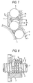
- a ball scooping path 22 formed in the boundary part between a ball return path 7b of the ball circulating tube 7 and a ball load rolling path 5 may have a length A greater than or equal to 1/2 of the diameter D of the balls 6. Also, in this case, an effect similar to that of the above-mentioned embodiment is obtained.
- the embodiment given above has been described for the case that the invention is applied to a ball screw device of an external circulation type where the balls are circulated in the outside of the nut.
- the invention is not limited to this.
- the invention may be applied to a ball screw device of an internal circulation type where the balls are circulated in the inside of the nut.
Landscapes
- Engineering & Computer Science (AREA)
- General Engineering & Computer Science (AREA)
- Mechanical Engineering (AREA)
- Transmission Devices (AREA)
Abstract
Description
- The present invention relates to a ball screw device for converting rotational motion into linear motion.
- In industrial machines such as a machine tool and an injection molding machine, a ball screw device of a tube circulation type as shown in FIG. 8 is used as a device for converting rotational motion into linear motion. The ball screw device comprises: a
screw shaft 1; and anut 2 having an inner periphery provided with aball screw groove 4 opposing aball screw groove 3 formed in the outer periphery of thescrew shaft 1. Then, a large number ofballs 6 serving as rolling elements are arranged in a ballload rolling path 5 formed between theball screw groove 3 and theball screw groove 4. Theseballs 6 roll on between theball screw grooves screw shaft 1 or thenut 2. Aflat part 2a formed in the outer periphery of thenut 2 is provided with aball circulating tube 7 for circulating theballs 6. Theball circulating tube 7 is fabricated by bending into a U-shape a tube material composed of metal. Theflat part 2a of thenut 2 is provided with two circulatingtube insertion holes 8 into each of which an end of theball circulating tube 7 is inserted. Theball circulating tube 7 has a tongue section at each end, so that theballs 6 rolling on between theball screw grooves ball screw grooves ball circulating tube 7. - In this ball screw device, the balls compete with each other in the ball
load rolling path 5 formed between theball screw grooves ball circulating tube 7. This jamming of the balls can cause rapid wear-out to theballs 6, or alternatively damage to the surface of theballs 6. Thus, in order to avoid the jamming of the balls, a device has been proposed in whichball retaining pieces 9 fabricated of resin are respectively arranged between the balls as shown in FIG. 9 (see Japanese Published Unexamined Patent Application No. 2003-269563 which is hereinafter referred as Patent Document 1). - Nevertheless, in the ball screw device described in the
Patent Document 1 given above, when the filling factor of the ball retainingpiecesbecomes small in theball circulation path, theball retaining piece 9 can be temporarily caught at astep 10 or agap 11 appearing near the outlet of theball circulating tube 7 or alternatively at thetongue section 7a of theball circulating tube 7, as shown in FIGS. 10A-10C. This causes trouble. In order that such temporary catch of the ball retaining piece should be avoided, the filling factor of theball retaining pieces 9 need to be managed strictly at the time of fabrication. Alternatively, accuracy needs to be improved in the machining of the circulatingtube insertion hole 8. Nevertheless, these approaches that the filling factor of theball retaining pieces 9 is managed strictly at the time of fabrication, and that the accuracy is improved in the machining of the circulatingtube insertion hole 8 cause a problem of a cost increase. The invention has been devised by focusing attention on this point. - An object of the invention is to provide a ball screw device free from the temporary catch of a ball retaining piece even when the filling factor of the ball retaining pieces is small in the ball circulation path.
- In order to achieve the object described above, a first aspect of the invention is a ball screw device comprising: a screw shaft having an outer periphery provided with a ball screw groove; a nut having an inner periphery provided with a ball screw groove opposing the ball screw groove of the screw shaft; a large number of balls rolling on a ball load rolling path formed between the ball screw groove of said screw shaft and the ball screw groove of said nut, in association with revolution of said screw shaft or said nut; and a ball circulating member having a ball return path for circulating these balls, wherein resin-fabricated ball retaining pieces for suppressing jamming of said balls are respectively arranged between the balls, and wherein said ball circulating member is provided with a ball scooping section for scooping up the balls rolling on between said ball screw grooves, along a line tangent to a center orbital circle of the balls.
- A second aspect of the invention is a ball screw device according to the first aspect, wherein saidball scooping section has a line-shaped ball scooping path section in a boundary part between said ball load rolling path and said ball return path, and wherein said ball scooping path section has a path length of 1/2D or greater relative to a diameter D of said ball.
- A third aspect of the invention is a ball screw device comprising: a screw shaft having an outer periphery provided with a ball screw groove; a nut having an inner periphery provided with a ball screw groove opposing the ball screw groove of the screw shaft; a large number of balls rolling on a ball load rolling path formed between the ball screw groove of said screw shaft and the ball screw groove of said nut, in association with revolution of said screw shaft or said nut; and a ball circulating tube having a ball return path for circulating these balls, wherein resin-fabricated ball retaining pieces for suppressing jamming of saidballs are respectively arranged between the balls, and wherein a ball- scooping path formed in a boundary part between saidball load rolling path and said ball return path has a length of 1/2 or greater of a diameter of said ball.
- In the ball screw device according to the first aspect of the invention, a ball circulating member is provided with a ball scooping section for scooping up the balls rolling on between the ball screw grooves, along a line tangent to the center orbital circle of the balls. Thus, in the boundary part between the ball load rolling path and the ball return path, the balls and the ball retaining pieces align almost linearly along the line tangent to the ball center orbital circle. Accordingly, in contrast to the case of the tube circulation type ball screw device, the orientation of the ball retaining piece does not largely change in the boundary part between the ball load rolling path and the ball return path. This avoids the temporary catch of the ball retaining piece even when the filling factor of the ball retaining pieces is small in the ball circulation path.
- In the ball screw device according to the second aspect of the invention, the path length of the ball scoopingpath section is set to be 1/2D or greater relative to the diameter D of the ball. This avoids more reliably the temporary catch of the ball retainingpiece even when the filling factor of the ball retaining pieces is small in the ball circulation path.
- In the ball screw device according to the third aspect of the invention, the length of the ball scooping path formed in the boundary part-between the ball load rolling path and the ball return path is set to be 1/2 or greater of the diameter of the ball. Thus, the discontinuous scooping section becomes distant from a portion where a step, a gap, or the like can arise. This avoids the temporary catch of the ball retaining piece even when the filling factor of the ball retaining pieces is small in the ball circulation path.
-
- FIG. 1 is a plan view of a ball screw device according to a first embodiment of the invention.
- FIG. 2 is a plan view of a nut shown in FIG. 1.
- FIG. 3 is a III-III sectional view of FIG. 1.
- FIG. 4 is a front view of a ball circulating member shown in FIG. 1.
- FIG. 5 is a bottom view of a ball circulating member shown in FIG. 1.
- FIG. 6 is a diagram showing the result of frequency analysis of the acoustic noise characteristics of a ball screw device.
- FIG. 7 is a sectional view showing the main part of a ball screw device according to a second embodiment of the invention.
- FIG. 8 is a sectional view of a tube circulation type ball screw device.
- FIG. 9 is a sectional view of a ball retaining piece.
- FIGS. 10A-10C are diagrams used for describing a problem in the related art.
- Embodiments of the invention are described below with reference to the drawings.
- FIGS. 1-5 show a ball screw device according to an embodiment of the invention. As shown in FIG. 1, the ball screw device according to an embodiment of the invention comprises a
screw shaft 1 and anut 2. Aball screw groove 3 is formed in the outer periphery of thescrew shaft 1. Theball screw groove 3 opposes a ball screw groove 4 (see FIG. 2) formed in the inner periphery of thenut 2. A large number ofballs 6 serving as rolling elements are arranged in a ball load rolling path 5 (see FIG. 3) formed between theball screw groove 3 and theball screw groove 4. - The
balls 6 are arranged in line along theball screw grooves Ball retaining pieces 9 fabricated of resin for avoiding jamming of the balls are respectively provided between theballs 6. Theseballs 6 roll on the ballload rolling path 5 in association with the revolution of thescrew shaft 1 or thenut 2. Aflat part 2a formed in the outer periphery of thenut 2 is provided with aball circulating member 12 fabricated of synthetic resin material. - The
ball circulating member 12 has a ball return path 13 (see FIG. 1) for circulating theballs 6 rolling on the ballload rolling path 5. Thus, theballs 6 having rolled through the ballload rolling path 5 are circulated through theball return path 13 of theball circulating member 12. As shown in FIGS. 3 and 4, theball circulating member 12 comprises: amain body 14 having afixing face 14a fixed to theflat part 2a of thenut 2; and columrx-shapedball scooping sections fixing face 14a of themain body 14 toward theflat part 2a of thenut 2. Theflat part 2a of thenut 2 is provided with circulatingmember insertion holes 17 and 18 (see FIG. 2) fitted respectively with theball scooping sections ball circulating member 12. These circulatingmember insertion holes ball screw groove 4 so as to avoid interference with theball screw groove 4 formed in the inner periphery of thenut 2. - As shown in FIG. 3, in the
ball scooping sections path section 19 for scooping up theballs 6 having rolled through the ballload rolling path 5, along a line S tangent to the center orbital circle BC of theballs 6 is provided in the boundary part between the ballload rolling path 5 and theball return path 13. As shown in FIG. 3, the ball scoopingpath section 19 has a path length L greater than or equal to 1/2D relative to the diameter D of theball 6. - The
ball circulating member 12 is fixed to theflat part 2a of thenut 2 with two screws 20 (see FIG. 1). Theflat part 2a of thenut 2 is provided with two tapped holes (not shown) into which thescrews 20 are inserted. Theball circulating member 12 is constructed from a pair of resin molded members 21 (see FIG. 5) . Each resin moldedmember 21 is provided with a ball return path forming groove (not shown) for forming theball return path 13. Theball circulating member 12 may be fixed to thenut 2 using a fixing component of the form of a metal cover. - In the ball screw device constructed as described here, the
ball scooping sections balls 6 rolling on between theball screw grooves balls 6 have been provided in theball circulating member 12. Thus, in the boundary part between the ballload rolling path 5 formed between theball screw grooves ball return path 13, theballs 6 and theball retaining pieces 9 align almost linearly along the line S tangent to the center orbital circle BS of theballs 6. Thus, in contrast to the case of the tube circulation type ball screw device, the orientation of the ball retaining piece does not largely change in the boundary part between the ball load rolling path and the ball return path. This avoids the temporary catch of theball retaining piece 9 even when the filling factor of theball retaining pieces 9 is small in the circulation path for theballs 6. Accordingly, the necessity is avoided that the accuracy should be improved in the machining of the circulating member insertion holes 17 and 18 in order to avoid the temporary catch of theball retaining piece 9. This avoids an increase in the machining cost. - Further, in the embodiment described above, the path length L of the ball scooping
path section 19 has been set to be 1/2D or greater relative to the diameter D of theball 6. Thus, in the boundary part between the ballload rolling path 5 formed between theball screw grooves ball return path 13, theball retaining pieces 9 align almost linearly along the line S tangent to the center orbital circle BS of theballs 6. This avoids more reliably the temporary catch of theball retaining piece 9. - Further, the
ball circulating member 12 has been fabricated from a synthetic resin material. Thus, in comparison with the case of a ball screw device employing a ball circulating member fabricated of metal, the occurrence of acoustic noise, vibration, and the like is suppressed. Furthermore, the circulatingmember insertion holes 17 and 18 have been formed in the shape of an ellipse along theball screw grooves ball screw groove 4, even when the diameter of theball 6 is increased. As a result, the tangent scooping method described above is applicable even when the groove pitch is small in the ball screw groove, or alternatively even when the ball screw groove is replaced with multiple screw grooves. - FIG. 6 shows a result of frequency analysis of the acoustic noise characteristics of a ball screw device having a shaft diameter of 25 mm and a ball diameter of 4.7625 mm in a case that the screw shaft of the ball screw device is revolved at a rate of 4000 min-1. In the figure, line a indicates the result of frequency analysis of the acoustic noise characteristics obtained when the ball retaining pieces are arranged between the balls, while line b indicates the result of frequency analysis of the acoustic noise characteristics obtained when the ball retaining pieces are not arranged between the balls.
- As seen from the result of frequency analysis of FIG. 6, when the ball retaining pieces are arranged between the balls, the acoustic noise level of the ball screw device is reduced, that is, a low acoustic noise effect is obtained, in comparison with the case that the ball retaining pieces are not arranged between the balls.
- The invention is not limited to the embodiment described above. For example, the embodiment given above has been described for the case that the invention is applied to a ball screw device of a tangent method in which the balls are scooped up along a line tangent to the center orbital circle of the balls. However, in a second embodiment shown in FIG. 7 where the ball circulating member is composed of a ball circulating tube, a
ball scooping path 22 formed in the boundary part between aball return path 7b of theball circulating tube 7 and a ballload rolling path 5 may have a length A greater than or equal to 1/2 of the diameter D of theballs 6. Also, in this case, an effect similar to that of the above-mentioned embodiment is obtained. - Further, the embodiment given above has been described for the case that the invention is applied to a ball screw device of an external circulation type where the balls are circulated in the outside of the nut. However, the invention is not limited to this. For example, the invention may be applied to a ball screw device of an internal circulation type where the balls are circulated in the inside of the nut.
Claims (3)
- A ball screw device comprising:a screw shaft having an outer periphery provided with a ball screw groove;a nut having an inner periphery provided with a ball screw groove opposing the ball screw groove of the screw shaft;a large number of balls rolling on a ball load rolling path formed between the ball screw groove of the screw shaft and the ball screw groove of the nut, in association with revolution of the screw shaft or the nut;a ball circulating member having a ball return path for circulating these balls; andresin-fabricated ball retaining pieces for suppressing jamming of the balls are respectively arranged between the balls,wherein the ball circulating member is provided with a ball scooping section for scooping up the balls roll ing on between the ball screw grooves, along a line tangent to a center orbital circle of the balls.
- A ball screw device according to Claim 1, wherein the ball scooping section has a line-shaped ball scooping path section in a boundary part between the ball load rolling path and the ball return path, and wherein the ball scooping path section has a path length of 1/2D or greater relative to a diameter D of the ball.
- A ball screw device comprising:a screw shaft having an outer periphery provided with a ball screw groove;a nut having an inner periphery provided with a ball screw groove opposing the ball screw groove of the screw shaft;a large number of balls rolling on a ball load rolling path formed between the ball screw groove of the screw shaft and the ball screw groove of the nut, in association with revolution of the screw shaft or the nut;a ball circulating tube having a ball return path for circulating these balls; andresin-fabricated ball retaining pieces for suppressing jamming of the balls are respectively arrangedbetween the balls,wherein a ball scooping path formed in a boundary part between the ball load rolling path and the ball return path has a length of 1/2 or greater of a diameter of the ball.
Applications Claiming Priority (1)
| Application Number | Priority Date | Filing Date | Title |
|---|---|---|---|
| JP2004229605A JP2006046530A (en) | 2004-08-05 | 2004-08-05 | Ball screw device |
Publications (3)
| Publication Number | Publication Date |
|---|---|
| EP1624227A2 true EP1624227A2 (en) | 2006-02-08 |
| EP1624227A3 EP1624227A3 (en) | 2009-09-16 |
| EP1624227B1 EP1624227B1 (en) | 2012-05-02 |
Family
ID=35612628
Family Applications (1)
| Application Number | Title | Priority Date | Filing Date |
|---|---|---|---|
| EP05016978A Expired - Lifetime EP1624227B1 (en) | 2004-08-05 | 2005-08-04 | Ball screw device |
Country Status (5)
| Country | Link |
|---|---|
| US (1) | US7921743B2 (en) |
| EP (1) | EP1624227B1 (en) |
| JP (1) | JP2006046530A (en) |
| CN (1) | CN100564948C (en) |
| AT (1) | ATE556251T1 (en) |
Families Citing this family (15)
| Publication number | Priority date | Publication date | Assignee | Title |
|---|---|---|---|---|
| CN100436875C (en) * | 2006-03-24 | 2008-11-26 | 南京工艺装备制造有限公司 | Plug-in ball screw pair |
| CN101432550B (en) * | 2006-04-28 | 2012-05-02 | Thk株式会社 | Screw device and manufacturing method thereof |
| US7516681B2 (en) * | 2007-07-13 | 2009-04-14 | Hiwin Technologies Corp. | External circulation type ball screw |
| JP5252279B2 (en) * | 2008-08-21 | 2013-07-31 | Smc株式会社 | Ball screw mechanism |
| TWI376469B (en) * | 2008-10-23 | 2012-11-11 | Hiwin Tech Corp | Nut structure of ball screw |
| US8051736B2 (en) * | 2009-01-06 | 2011-11-08 | Hiwin Technologies Corp. | Deflecting device for ball screw device |
| US8640564B2 (en) * | 2009-12-29 | 2014-02-04 | Hiwin Technologies Corp. | Circulation element for ball screw |
| US9003911B2 (en) * | 2010-12-08 | 2015-04-14 | Nsk Ltd. | Ball screw device |
| FR2980254B1 (en) * | 2011-09-21 | 2014-05-23 | Skf Ab | BALL SCREW SYSTEM PROVIDED WITH A MEANS FOR RETAINING A BALL DEVIATION ELEMENT |
| US9133922B2 (en) * | 2013-03-11 | 2015-09-15 | Hiwin Technologies Corp. | Load adjustable ball screw device |
| JP5898638B2 (en) * | 2013-03-25 | 2016-04-06 | 日立オートモティブシステムズステアリング株式会社 | Power steering device |
| JP6244108B2 (en) * | 2013-05-31 | 2017-12-06 | Thk株式会社 | Screw device |
| JP1524391S (en) * | 2014-07-10 | 2015-05-25 | ||
| JP1524390S (en) * | 2014-07-10 | 2015-05-25 | ||
| CN107110315B (en) * | 2015-01-16 | 2019-06-14 | 日立汽车系统株式会社 | Power steering device and method of making the same |
Citations (1)
| Publication number | Priority date | Publication date | Assignee | Title |
|---|---|---|---|---|
| JP2003269563A (en) | 2002-03-18 | 2003-09-25 | Nsk Ltd | Ball screw |
Family Cites Families (21)
| Publication number | Priority date | Publication date | Assignee | Title |
|---|---|---|---|---|
| FR2230238A5 (en) | 1973-05-16 | 1974-12-13 | Tech Integrale | |
| US5063809A (en) * | 1990-10-15 | 1991-11-12 | Dana Corporation | Return tube arrangement for ball screw assembly |
| JPH0654953U (en) | 1992-12-29 | 1994-07-26 | 光洋機械工業株式会社 | Ball screw |
| US5791192A (en) * | 1994-10-03 | 1998-08-11 | Lee; Mouton | Ball return and piece structure of internal circulation type ball screw system |
| JP4220018B2 (en) | 1998-06-26 | 2009-02-04 | Thk株式会社 | Ball screw |
| US6176149B1 (en) * | 1999-05-28 | 2001-01-23 | Tsubaki Nakashima Co., Ltd. | Ball screw having spacers |
| US6681651B2 (en) * | 2000-07-18 | 2004-01-27 | Thk Co., Ltd. | Ball screw |
| JP4742482B2 (en) * | 2000-11-07 | 2011-08-10 | 日本精工株式会社 | Ball screw |
| JP2002276764A (en) * | 2001-03-22 | 2002-09-25 | Ntn Corp | Ball screw |
| JP2002339967A (en) * | 2001-05-15 | 2002-11-27 | Nsk Ltd | Linear motion bearing device |
| JP2003074663A (en) * | 2001-09-05 | 2003-03-12 | Nsk Ltd | Ball screw |
| JP3993504B2 (en) | 2001-12-05 | 2007-10-17 | Thk株式会社 | Ball screw circulation parts and ball screw |
| US20030172759A1 (en) * | 2002-02-25 | 2003-09-18 | Nsk Ltd. | Ball screw |
| JP2004156767A (en) | 2002-02-25 | 2004-06-03 | Nsk Ltd | Ball screw |
| JP2003294105A (en) * | 2002-03-29 | 2003-10-15 | Nsk Ltd | Screw feeder |
| JP2003329102A (en) | 2002-05-15 | 2003-11-19 | Nsk Ltd | Ball screw device |
| JP4110834B2 (en) | 2002-05-23 | 2008-07-02 | 日本精工株式会社 | Ball screw |
| JP4053826B2 (en) | 2002-06-25 | 2008-02-27 | Thk株式会社 | Circulating component, and motion guide device and ball screw using the circulating component |
| US7523681B2 (en) * | 2006-12-07 | 2009-04-28 | Hiwin Technologies Corp. | Ball screw device having deflecting member background of the invention |
| TWI338095B (en) * | 2008-08-29 | 2011-03-01 | Hiwin Tech Corp | Ball screw module and circulating device therein |
| TWI368697B (en) * | 2008-10-31 | 2012-07-21 | Hiwin Tech Corp | Circulation element for ball screw |
-
2004
- 2004-08-05 JP JP2004229605A patent/JP2006046530A/en not_active Withdrawn
-
2005
- 2005-08-04 AT AT05016978T patent/ATE556251T1/en active
- 2005-08-04 CN CNB2005100910417A patent/CN100564948C/en not_active Expired - Lifetime
- 2005-08-04 EP EP05016978A patent/EP1624227B1/en not_active Expired - Lifetime
- 2005-08-05 US US11/197,522 patent/US7921743B2/en active Active
Patent Citations (1)
| Publication number | Priority date | Publication date | Assignee | Title |
|---|---|---|---|---|
| JP2003269563A (en) | 2002-03-18 | 2003-09-25 | Nsk Ltd | Ball screw |
Also Published As
| Publication number | Publication date |
|---|---|
| CN100564948C (en) | 2009-12-02 |
| US7921743B2 (en) | 2011-04-12 |
| US20060027038A1 (en) | 2006-02-09 |
| JP2006046530A (en) | 2006-02-16 |
| EP1624227B1 (en) | 2012-05-02 |
| CN1737407A (en) | 2006-02-22 |
| EP1624227A3 (en) | 2009-09-16 |
| ATE556251T1 (en) | 2012-05-15 |
Similar Documents
| Publication | Publication Date | Title |
|---|---|---|
| US7921743B2 (en) | Ball screw device | |
| CN100494732C (en) | Ball screw unit | |
| EP1515066A2 (en) | Ball screw apparatus | |
| JP2003294105A (en) | Screw feeder | |
| EP2487388B1 (en) | Ball screw device | |
| US6450055B1 (en) | Ball screw apparatus | |
| US20050016308A1 (en) | Tube guide for ball screw, ball screw and method for manufacturing thereof | |
| KR20200001220U (en) | Ball screw | |
| JP2007255435A (en) | Rolling element screw device and manufacturing method for rolling element screw device | |
| JP4727247B2 (en) | Top ball screw | |
| JPH028178B2 (en) | ||
| JP2004156767A (en) | Ball screw | |
| JP3150527U (en) | Rolling element screw device | |
| JP2005155720A (en) | Screw device and its manufacturing method | |
| JP6859688B2 (en) | Ball screw | |
| EP1624228B1 (en) | Ball circulating member and ball screw | |
| EP1837556B1 (en) | Ball screw device | |
| JP4525233B2 (en) | Ball circulation member and ball screw | |
| JP4110834B2 (en) | Ball screw | |
| JP2007147028A (en) | Rolling element screw device and method of manufacturing its circulation member | |
| JP4779648B2 (en) | Ball screw device | |
| JPH10205603A (en) | Ball circulation tube of ball screw | |
| KR102858061B1 (en) | Ball screw device | |
| JP2007218278A (en) | Ball screw device | |
| US20110314941A1 (en) | Sectional circulating assembly for a ball screw |
Legal Events
| Date | Code | Title | Description |
|---|---|---|---|
| PUAI | Public reference made under article 153(3) epc to a published international application that has entered the european phase |
Free format text: ORIGINAL CODE: 0009012 |
|
| AK | Designated contracting states |
Kind code of ref document: A2 Designated state(s): AT BE BG CH CY CZ DE DK EE ES FI FR GB GR HU IE IS IT LI LT LU LV MC NL PL PT RO SE SI SK TR |
|
| AX | Request for extension of the european patent |
Extension state: AL BA HR MK YU |
|
| PUAL | Search report despatched |
Free format text: ORIGINAL CODE: 0009013 |
|
| AK | Designated contracting states |
Kind code of ref document: A3 Designated state(s): AT BE BG CH CY CZ DE DK EE ES FI FR GB GR HU IE IS IT LI LT LU LV MC NL PL PT RO SE SI SK TR |
|
| AX | Request for extension of the european patent |
Extension state: AL BA HR MK YU |
|
| 17P | Request for examination filed |
Effective date: 20100310 |
|
| AKX | Designation fees paid |
Designated state(s): AT BE BG CH CY CZ DE DK EE ES FI FR GB GR HU IE IS IT LI LT LU LV MC NL PL PT RO SE SI SK TR |
|
| 17Q | First examination report despatched |
Effective date: 20100819 |
|
| GRAP | Despatch of communication of intention to grant a patent |
Free format text: ORIGINAL CODE: EPIDOSNIGR1 |
|
| RIN1 | Information on inventor provided before grant (corrected) |
Inventor name: OHKUBO, TSUTOMUC/O NSK LTD. Inventor name: MINAKAMI, ATSUSHIC/O NSK LTD. |
|
| GRAS | Grant fee paid |
Free format text: ORIGINAL CODE: EPIDOSNIGR3 |
|
| GRAA | (expected) grant |
Free format text: ORIGINAL CODE: 0009210 |
|
| AK | Designated contracting states |
Kind code of ref document: B1 Designated state(s): AT BE BG CH CY CZ DE DK EE ES FI FR GB GR HU IE IS IT LI LT LU LV MC NL PL PT RO SE SI SK TR |
|
| REG | Reference to a national code |
Ref country code: GB Ref legal event code: FG4D |
|
| REG | Reference to a national code |
Ref country code: CH Ref legal event code: EP Ref country code: AT Ref legal event code: REF Ref document number: 556251 Country of ref document: AT Kind code of ref document: T Effective date: 20120515 |
|
| REG | Reference to a national code |
Ref country code: IE Ref legal event code: FG4D |
|
| REG | Reference to a national code |
Ref country code: DE Ref legal event code: R096 Ref document number: 602005033950 Country of ref document: DE Effective date: 20120712 |
|
| REG | Reference to a national code |
Ref country code: NL Ref legal event code: VDEP Effective date: 20120502 |
|
| REG | Reference to a national code |
Ref country code: LT Ref legal event code: MG4D Effective date: 20120502 |
|
| PG25 | Lapsed in a contracting state [announced via postgrant information from national office to epo] |
Ref country code: LT Free format text: LAPSE BECAUSE OF FAILURE TO SUBMIT A TRANSLATION OF THE DESCRIPTION OR TO PAY THE FEE WITHIN THE PRESCRIBED TIME-LIMIT Effective date: 20120502 Ref country code: CY Free format text: LAPSE BECAUSE OF FAILURE TO SUBMIT A TRANSLATION OF THE DESCRIPTION OR TO PAY THE FEE WITHIN THE PRESCRIBED TIME-LIMIT Effective date: 20120502 Ref country code: PL Free format text: LAPSE BECAUSE OF FAILURE TO SUBMIT A TRANSLATION OF THE DESCRIPTION OR TO PAY THE FEE WITHIN THE PRESCRIBED TIME-LIMIT Effective date: 20120502 Ref country code: FI Free format text: LAPSE BECAUSE OF FAILURE TO SUBMIT A TRANSLATION OF THE DESCRIPTION OR TO PAY THE FEE WITHIN THE PRESCRIBED TIME-LIMIT Effective date: 20120502 Ref country code: SE Free format text: LAPSE BECAUSE OF FAILURE TO SUBMIT A TRANSLATION OF THE DESCRIPTION OR TO PAY THE FEE WITHIN THE PRESCRIBED TIME-LIMIT Effective date: 20120502 Ref country code: IS Free format text: LAPSE BECAUSE OF FAILURE TO SUBMIT A TRANSLATION OF THE DESCRIPTION OR TO PAY THE FEE WITHIN THE PRESCRIBED TIME-LIMIT Effective date: 20120902 |
|
| REG | Reference to a national code |
Ref country code: AT Ref legal event code: MK05 Ref document number: 556251 Country of ref document: AT Kind code of ref document: T Effective date: 20120502 |
|
| PG25 | Lapsed in a contracting state [announced via postgrant information from national office to epo] |
Ref country code: PT Free format text: LAPSE BECAUSE OF FAILURE TO SUBMIT A TRANSLATION OF THE DESCRIPTION OR TO PAY THE FEE WITHIN THE PRESCRIBED TIME-LIMIT Effective date: 20120903 Ref country code: GR Free format text: LAPSE BECAUSE OF FAILURE TO SUBMIT A TRANSLATION OF THE DESCRIPTION OR TO PAY THE FEE WITHIN THE PRESCRIBED TIME-LIMIT Effective date: 20120803 Ref country code: LV Free format text: LAPSE BECAUSE OF FAILURE TO SUBMIT A TRANSLATION OF THE DESCRIPTION OR TO PAY THE FEE WITHIN THE PRESCRIBED TIME-LIMIT Effective date: 20120502 Ref country code: SI Free format text: LAPSE BECAUSE OF FAILURE TO SUBMIT A TRANSLATION OF THE DESCRIPTION OR TO PAY THE FEE WITHIN THE PRESCRIBED TIME-LIMIT Effective date: 20120502 |
|
| PG25 | Lapsed in a contracting state [announced via postgrant information from national office to epo] |
Ref country code: BE Free format text: LAPSE BECAUSE OF FAILURE TO SUBMIT A TRANSLATION OF THE DESCRIPTION OR TO PAY THE FEE WITHIN THE PRESCRIBED TIME-LIMIT Effective date: 20120502 |
|
| PG25 | Lapsed in a contracting state [announced via postgrant information from national office to epo] |
Ref country code: DK Free format text: LAPSE BECAUSE OF FAILURE TO SUBMIT A TRANSLATION OF THE DESCRIPTION OR TO PAY THE FEE WITHIN THE PRESCRIBED TIME-LIMIT Effective date: 20120502 Ref country code: CZ Free format text: LAPSE BECAUSE OF FAILURE TO SUBMIT A TRANSLATION OF THE DESCRIPTION OR TO PAY THE FEE WITHIN THE PRESCRIBED TIME-LIMIT Effective date: 20120502 Ref country code: NL Free format text: LAPSE BECAUSE OF FAILURE TO SUBMIT A TRANSLATION OF THE DESCRIPTION OR TO PAY THE FEE WITHIN THE PRESCRIBED TIME-LIMIT Effective date: 20120502 Ref country code: SK Free format text: LAPSE BECAUSE OF FAILURE TO SUBMIT A TRANSLATION OF THE DESCRIPTION OR TO PAY THE FEE WITHIN THE PRESCRIBED TIME-LIMIT Effective date: 20120502 Ref country code: RO Free format text: LAPSE BECAUSE OF FAILURE TO SUBMIT A TRANSLATION OF THE DESCRIPTION OR TO PAY THE FEE WITHIN THE PRESCRIBED TIME-LIMIT Effective date: 20120502 Ref country code: AT Free format text: LAPSE BECAUSE OF FAILURE TO SUBMIT A TRANSLATION OF THE DESCRIPTION OR TO PAY THE FEE WITHIN THE PRESCRIBED TIME-LIMIT Effective date: 20120502 Ref country code: EE Free format text: LAPSE BECAUSE OF FAILURE TO SUBMIT A TRANSLATION OF THE DESCRIPTION OR TO PAY THE FEE WITHIN THE PRESCRIBED TIME-LIMIT Effective date: 20120502 |
|
| PG25 | Lapsed in a contracting state [announced via postgrant information from national office to epo] |
Ref country code: IT Free format text: LAPSE BECAUSE OF FAILURE TO SUBMIT A TRANSLATION OF THE DESCRIPTION OR TO PAY THE FEE WITHIN THE PRESCRIBED TIME-LIMIT Effective date: 20120502 |
|
| PLBE | No opposition filed within time limit |
Free format text: ORIGINAL CODE: 0009261 |
|
| STAA | Information on the status of an ep patent application or granted ep patent |
Free format text: STATUS: NO OPPOSITION FILED WITHIN TIME LIMIT |
|
| REG | Reference to a national code |
Ref country code: CH Ref legal event code: PL |
|
| PG25 | Lapsed in a contracting state [announced via postgrant information from national office to epo] |
Ref country code: MC Free format text: LAPSE BECAUSE OF NON-PAYMENT OF DUE FEES Effective date: 20120831 |
|
| 26N | No opposition filed |
Effective date: 20130205 |
|
| GBPC | Gb: european patent ceased through non-payment of renewal fee |
Effective date: 20120804 |
|
| PG25 | Lapsed in a contracting state [announced via postgrant information from national office to epo] |
Ref country code: LI Free format text: LAPSE BECAUSE OF NON-PAYMENT OF DUE FEES Effective date: 20120831 Ref country code: CH Free format text: LAPSE BECAUSE OF NON-PAYMENT OF DUE FEES Effective date: 20120831 Ref country code: ES Free format text: LAPSE BECAUSE OF FAILURE TO SUBMIT A TRANSLATION OF THE DESCRIPTION OR TO PAY THE FEE WITHIN THE PRESCRIBED TIME-LIMIT Effective date: 20120813 |
|
| REG | Reference to a national code |
Ref country code: FR Ref legal event code: ST Effective date: 20130430 |
|
| REG | Reference to a national code |
Ref country code: IE Ref legal event code: MM4A |
|
| REG | Reference to a national code |
Ref country code: DE Ref legal event code: R097 Ref document number: 602005033950 Country of ref document: DE Effective date: 20130205 |
|
| PG25 | Lapsed in a contracting state [announced via postgrant information from national office to epo] |
Ref country code: BG Free format text: LAPSE BECAUSE OF FAILURE TO SUBMIT A TRANSLATION OF THE DESCRIPTION OR TO PAY THE FEE WITHIN THE PRESCRIBED TIME-LIMIT Effective date: 20120802 Ref country code: GB Free format text: LAPSE BECAUSE OF NON-PAYMENT OF DUE FEES Effective date: 20120804 Ref country code: IE Free format text: LAPSE BECAUSE OF NON-PAYMENT OF DUE FEES Effective date: 20120804 |
|
| PG25 | Lapsed in a contracting state [announced via postgrant information from national office to epo] |
Ref country code: FR Free format text: LAPSE BECAUSE OF NON-PAYMENT OF DUE FEES Effective date: 20120831 |
|
| PG25 | Lapsed in a contracting state [announced via postgrant information from national office to epo] |
Ref country code: TR Free format text: LAPSE BECAUSE OF FAILURE TO SUBMIT A TRANSLATION OF THE DESCRIPTION OR TO PAY THE FEE WITHIN THE PRESCRIBED TIME-LIMIT Effective date: 20120502 |
|
| PG25 | Lapsed in a contracting state [announced via postgrant information from national office to epo] |
Ref country code: LU Free format text: LAPSE BECAUSE OF NON-PAYMENT OF DUE FEES Effective date: 20120804 |
|
| PG25 | Lapsed in a contracting state [announced via postgrant information from national office to epo] |
Ref country code: HU Free format text: LAPSE BECAUSE OF FAILURE TO SUBMIT A TRANSLATION OF THE DESCRIPTION OR TO PAY THE FEE WITHIN THE PRESCRIBED TIME-LIMIT Effective date: 20050804 |
|
| PGFP | Annual fee paid to national office [announced via postgrant information from national office to epo] |
Ref country code: DE Payment date: 20230627 Year of fee payment: 19 |
|
| REG | Reference to a national code |
Ref country code: DE Ref legal event code: R119 Ref document number: 602005033950 Country of ref document: DE |
|
| PG25 | Lapsed in a contracting state [announced via postgrant information from national office to epo] |
Ref country code: DE Free format text: LAPSE BECAUSE OF NON-PAYMENT OF DUE FEES Effective date: 20250301 |