EP1624200B1 - A device and a method for releasably holding two articles together - Google Patents
A device and a method for releasably holding two articles together Download PDFInfo
- Publication number
- EP1624200B1 EP1624200B1 EP04018661A EP04018661A EP1624200B1 EP 1624200 B1 EP1624200 B1 EP 1624200B1 EP 04018661 A EP04018661 A EP 04018661A EP 04018661 A EP04018661 A EP 04018661A EP 1624200 B1 EP1624200 B1 EP 1624200B1
- Authority
- EP
- European Patent Office
- Prior art keywords
- opening
- articles
- lug
- lug portion
- wedge
- Prior art date
- Legal status (The legal status is an assumption and is not a legal conclusion. Google has not performed a legal analysis and makes no representation as to the accuracy of the status listed.)
- Not-in-force
Links
- 238000000034 method Methods 0.000 title claims description 14
- 125000006850 spacer group Chemical group 0.000 claims description 11
- 238000003825 pressing Methods 0.000 claims description 8
- 238000005553 drilling Methods 0.000 claims description 7
- 238000003754 machining Methods 0.000 claims description 3
- 239000000463 material Substances 0.000 claims description 3
- 238000007789 sealing Methods 0.000 description 4
- 238000005406 washing Methods 0.000 description 3
- 238000003801 milling Methods 0.000 description 2
- 230000001419 dependent effect Effects 0.000 description 1
- 238000012423 maintenance Methods 0.000 description 1
- 239000002245 particle Substances 0.000 description 1
- 238000004080 punching Methods 0.000 description 1
- 230000003014 reinforcing effect Effects 0.000 description 1
Images


Classifications
-
- F—MECHANICAL ENGINEERING; LIGHTING; HEATING; WEAPONS; BLASTING
- F16—ENGINEERING ELEMENTS AND UNITS; GENERAL MEASURES FOR PRODUCING AND MAINTAINING EFFECTIVE FUNCTIONING OF MACHINES OR INSTALLATIONS; THERMAL INSULATION IN GENERAL
- F16B—DEVICES FOR FASTENING OR SECURING CONSTRUCTIONAL ELEMENTS OR MACHINE PARTS TOGETHER, e.g. NAILS, BOLTS, CIRCLIPS, CLAMPS, CLIPS OR WEDGES; JOINTS OR JOINTING
- F16B5/00—Joining sheets or plates, e.g. panels, to one another or to strips or bars parallel to them
- F16B5/02—Joining sheets or plates, e.g. panels, to one another or to strips or bars parallel to them by means of fastening members using screw-thread
- F16B5/0291—Joining sheets or plates, e.g. panels, to one another or to strips or bars parallel to them by means of fastening members using screw-thread the threaded element being driven through the edge of a sheet plate with its axis in the plane of the plate
-
- B—PERFORMING OPERATIONS; TRANSPORTING
- B25—HAND TOOLS; PORTABLE POWER-DRIVEN TOOLS; MANIPULATORS
- B25B—TOOLS OR BENCH DEVICES NOT OTHERWISE PROVIDED FOR, FOR FASTENING, CONNECTING, DISENGAGING OR HOLDING
- B25B31/00—Hand tools for applying fasteners
- B25B31/005—Hand tools for applying fasteners for temporarily connecting sheets before or during assembly operations
-
- B—PERFORMING OPERATIONS; TRANSPORTING
- B64—AIRCRAFT; AVIATION; COSMONAUTICS
- B64C—AEROPLANES; HELICOPTERS
- B64C1/00—Fuselages; Constructional features common to fuselages, wings, stabilising surfaces or the like
- B64C1/06—Frames; Stringers; Longerons ; Fuselage sections
-
- B—PERFORMING OPERATIONS; TRANSPORTING
- B64—AIRCRAFT; AVIATION; COSMONAUTICS
- B64C—AEROPLANES; HELICOPTERS
- B64C3/00—Wings
- B64C3/18—Spars; Ribs; Stringers
- B64C3/187—Ribs
-
- F—MECHANICAL ENGINEERING; LIGHTING; HEATING; WEAPONS; BLASTING
- F16—ENGINEERING ELEMENTS AND UNITS; GENERAL MEASURES FOR PRODUCING AND MAINTAINING EFFECTIVE FUNCTIONING OF MACHINES OR INSTALLATIONS; THERMAL INSULATION IN GENERAL
- F16B—DEVICES FOR FASTENING OR SECURING CONSTRUCTIONAL ELEMENTS OR MACHINE PARTS TOGETHER, e.g. NAILS, BOLTS, CIRCLIPS, CLAMPS, CLIPS OR WEDGES; JOINTS OR JOINTING
- F16B5/00—Joining sheets or plates, e.g. panels, to one another or to strips or bars parallel to them
- F16B5/07—Joining sheets or plates, e.g. panels, to one another or to strips or bars parallel to them by means of multiple interengaging protrusions on the surfaces, e.g. hooks, coils
-
- F—MECHANICAL ENGINEERING; LIGHTING; HEATING; WEAPONS; BLASTING
- F16—ENGINEERING ELEMENTS AND UNITS; GENERAL MEASURES FOR PRODUCING AND MAINTAINING EFFECTIVE FUNCTIONING OF MACHINES OR INSTALLATIONS; THERMAL INSULATION IN GENERAL
- F16B—DEVICES FOR FASTENING OR SECURING CONSTRUCTIONAL ELEMENTS OR MACHINE PARTS TOGETHER, e.g. NAILS, BOLTS, CIRCLIPS, CLAMPS, CLIPS OR WEDGES; JOINTS OR JOINTING
- F16B5/00—Joining sheets or plates, e.g. panels, to one another or to strips or bars parallel to them
- F16B5/02—Joining sheets or plates, e.g. panels, to one another or to strips or bars parallel to them by means of fastening members using screw-thread
-
- Y—GENERAL TAGGING OF NEW TECHNOLOGICAL DEVELOPMENTS; GENERAL TAGGING OF CROSS-SECTIONAL TECHNOLOGIES SPANNING OVER SEVERAL SECTIONS OF THE IPC; TECHNICAL SUBJECTS COVERED BY FORMER USPC CROSS-REFERENCE ART COLLECTIONS [XRACs] AND DIGESTS
- Y10—TECHNICAL SUBJECTS COVERED BY FORMER USPC
- Y10T—TECHNICAL SUBJECTS COVERED BY FORMER US CLASSIFICATION
- Y10T29/00—Metal working
- Y10T29/53—Means to assemble or disassemble
- Y10T29/53978—Means to assemble or disassemble including means to relatively position plural work parts
-
- Y—GENERAL TAGGING OF NEW TECHNOLOGICAL DEVELOPMENTS; GENERAL TAGGING OF CROSS-SECTIONAL TECHNOLOGIES SPANNING OVER SEVERAL SECTIONS OF THE IPC; TECHNICAL SUBJECTS COVERED BY FORMER USPC CROSS-REFERENCE ART COLLECTIONS [XRACs] AND DIGESTS
- Y10—TECHNICAL SUBJECTS COVERED BY FORMER USPC
- Y10T—TECHNICAL SUBJECTS COVERED BY FORMER US CLASSIFICATION
- Y10T403/00—Joints and connections
- Y10T403/46—Rod end to transverse side of member
- Y10T403/4602—Corner joint
Definitions
- the present invention relates to a device for releasably holding two articles together in a mutually fixed position as well as a method according to the preambles of claims 1 and 13 respectively (see, for example, US-4, 892, 435-A).
- the articles may be any type of articles to be held together in a mutually fixed position with a high accuracy most often for being permanently secured to each other in this position.
- the articles are only held together in said position for being treated in any way, such as through drilling, punching, broaching, sawing or the like in this position.
- Such a device and method are for instance of great interest and used for holding two articles together in a mutually fixed position when assembling such articles to form an airplane fuselage, and this particular field of use of the present invention will hereinafter be discussed for illuminating the invention and the problems to be solved thereby without for that sake limiting the invention to this field of use.
- the object of the present invention is to provide a device and a method at least partially solving the problems mentioned above.
- the time for assembling in jigs is substantially reduced, especially since the machine articles may be held that tightly in said mutually fixed position that no drillings or the like will enter any space between the articles, since such spaces are not there, and there is accordingly no need to remove the articles from the jigs after drilling and the like for burring, washing and application of sealing means, but the articles may be held together in a mutually fixed position throughout the assembling procedure.
- only one of said two lug portions having delimiting surfaces to be moved into alignment has an opening surroundingly delimited by lug portion walls and the opening of the other lug portion is laterally opened in the direction away from said first article in said fixed position and by that groove-like. It is often easier to obtain such a groove-like opening in a lug portion than an opening having surrounding delimiting walls, and it has been found out that one of the openings may be of that type, which will save time and costs.
- said first lug portion has a said groove-like opening.
- Said second lug portion is namely normally located at an edge of an article in the form of a plate-like member, whereas the first lug portion is normally located close to an opening through the large side of such a plate-like member.
- said tool has a wedge-like character so as to by wedge action obtain said pressing into alignment of said delimiting surfaces to each other in said fixed position.
- the tool has a wedge-shaped part adapted to have the most narrow end thereof firstly introduced through said two openings of adjacent lug portions, and the tool comprises means for engagement with the most narrow end of the wedge-shaped part for applying a force thereon for pressing this part in the direction of said introduction.
- the tool further comprises a member to be engaged with a thicker end of the wedge-shaped part not possible to be brought through the openings of the lug portions so as to apply forces on the wedge-shaped part in the opposite direction to the direction of introduction and by that press said surrounding surfaces of the two lug portions to bear against each other.
- Said engagements are preferably obtained by threaded bores in the wedge-shaped part and threaded male members, such as screws, tightened against spacers arranged on the respective lug portion.
- the tool has a wedge-shaped part to be introduced through the two openings of two adjacent lug portions in the direction of the narrowest end thereof, and the wedge-shaped part has a substantially rectangular cross-section as seen in the direction of the introduction intended.
- a wedge-shaped part of this design allows an accurate definition of the fixed position, and this is especially the case when two adjacent sides of the wedge-shaped part converges towards the respective opposite side in the direction towards the most narrow end of said part, while the other adjacent sides thereof extends substantially in parallel with said direction, and two adjacent said sides delimiting surfaces of each opening in said lug portions are correspondingly inclined for tightly bearing against the two sides first mentioned of the wedge-shaped part.
- a groove-like opening in one of the lug portions one of said two other sides of the wedge-shaped part has to co-operate with the "bottom" of said groove.
- the device has means adapted to fix the two articles with respect to each other on a location at a distance from said tool for preventing the articles held together to rotate about said tool, and this fixing means may then comprise a further said tool adapted to co-operate in the same way as the tool first mentioned with lug portions and openings of the articles on said location.
- said further tool may be slightly simplified with respect to the tool first mentioned, since it should mostly only have to fix the two articles with respect to each other in one or two dimensions.
- the invention also relates to a method for permanently securing at least two articles to each other, in which the articles are brought into a mutually fixed position and are while holding them in this position permanently secured to each other according to the corresponding appended claim. Also the features and advantages thereof appear from the discussion above of the device according to the invention.
- Fig 1 shows a part of a rear rib 1 of an airplane fuselage in the form of a first machine article to be secured to another, second machine article 2 in the form of an intermediate wall shown in fig 2.
- the different members such as reinforcing flanges 3, 3' and a lug portion 9, have been obtained from a single material piece through machining, here milling. This results in very small tolerances of the dimensions of these members.
- a device for releasably holding the two machine articles 1, 2 together in a mutually fixed position comprises a first opening 5 in the first machine article 1 through which a second lug portion 6 projecting from an end surface 7 of the second article 2 is designed to be moved from a first side 8 of the first article, so that this end surface 7 bears tightly against said first side 8.
- the first article has a first projecting lug portion 9 arranged on the opposite second side 10 of the first article adjacent to said first opening 5.
- the two lug portions have an opening 11, 12 each passing therethrough transversely to said first opening 5 when the second lug portion 6 is introduced through this opening.
- the opening 12 in the second lug portion is surroundingly delimited by lug portion walls, whereas the opening 11 of the first lug portion 9 is laterally opened in the direction away from the first article and by that groove-like. It is necessary that one of the two openings has surroundingly delimiting walls, and it is easier to accomplish this in the lug portion on the end surface than the lug portion arranged on a large surface of an article. Both lug portion openings may of course have surroundingly delimiting walls when desired.
- the two lug portions are arranged to be located with their openings at least partially overlapping when the second lug portion 6 is introduced through said first opening 5. Furthermore, the respective lug portion opening is designed to have at least two surfaces defining it in alignment with corresponding surfaces defining the lug portion opening of the adjacent lug portion for defining said fixed position with respect to two dimensions, namely in a plane parallel to surfaces 13 surrounding the opening 11 of the first lug portion 9 and here being perpendicular to the large surface 14 of the first article. Said surfaces to be in alignment are the bottom surface 15 of the opening 11 in the first lug portion 9, the corresponding surface 16 in the second lug portion 6 and one surface 17, 18 of each of these openings perpendicular thereto, in this case the upper surfaces as seen in fig 1 and 2.
- the device also comprises a tool 20 illustrated in fig 3 and 4 adapted to hold the articles together in said mutually fixed position. How this is obtained is illustrated in fig 5.
- the tool has a wedge-shaped part 21 adapted to be introduced through the openings 11, 12 of adjacent lug portions 6, 9 and press them into alignment of said defining surfaces 15, 16 and 17, 18 and said surrounding surfaces 13, 19 to bear under pretension against each other for holding the articles in a mutually fixed position.
- the wedge-shaped part 21 has a rectangular cross-section, in this case a square cross-section, with two adjacent sides 22, 23 converging towards the respective opposite side 24, 25 in the direction towards the narrowest end 26 of this part 21.
- the other adjacent sides 24, 25 extend substantially in parallel with said direction.
- Corresponding surfaces of the openings in the lug portions are correspondingly inclined, which in this case is the lower surface 27 of the first lug portion 9 and the lower surface 28 and the surface 29 opposite to the surface 16 of the second lug portion 6.
- the wedge-shaped part 21 has a threaded bore 30 extending therethrough.
- a first spacer 31 in the form of a sleeve is adapted to be applied upon the first lug portion around said most narrow end 26 of the wedge-shaped part when this is introduced through the lug portion openings and to be tightened against this lug portion by tightening a head 33 of a screw 32 engaging the bore 30 thereagainst.
- By tightening said screw 32 the wedge-shaped part is forced further through the openings 11, 12 of the lug portions for pressing the lug portions to a very exact alignment of said opening surfaces thereof and by that definition of said mutually fixed position in two dimensions.
- the tool also comprises a second spacer 34 also having a sleeve-like character to be applied on the second lug portion and tightened thereagainst by a screw 35 engaging the threaded bore 30 from the thicker end 36 of the wedge-shaped part 21 with the head 37 of the screw against the spacer.
- a screw 35 engaging the threaded bore 30 from the thicker end 36 of the wedge-shaped part 21 with the head 37 of the screw against the spacer.
- the fixing of the two articles 1, 2 in said mutually fixed position will take place in the following way.
- the second lug portion 6 is firstly introduced through the first opening 5 of the first article 1, so that the openings 11, 12 of the lug portions will overlap.
- the wedge-shaped part 21 is then introduced with the narrowest end 26 first through the two openings of the lug portions as shown in fig 5.
- the first spacer 31 is after that applied onto the first lug portion and the screw 32 introduced therethrough and through the bore 30 and tightened so as to pull the wedge-shaped part 21 as much as possible through said openings of the lug portions for defining said fixed position into dimensions perpendicular to the direction of introduction of the wedge-shaped part.
- the second spacer 34 is after that applied on the second lug portion and the screw 35 is introduced therethrough and through the bore 30 and tightened for pressing the surfaces 13 and 19 of the lug portions against each other for defining said fixed position in a third dimension corresponding to the direction of said introduction.
- the device also comprises means adapted to fix the two articles with respect to each other on a location at a distance from said tool, and this means is in this case a further such tool 20'.
- This tool 20' has only to fix the articles in two dimensions, namely in the direction of said introduction of the wedge-shaped part and in the direction of introduction of the second lug portion in the first opening of the first article. This means that the articles are prevented from rotating about the first tool 20.
- a number of such articles may in this way be mutually fixed and then in said fixed state be subjected to for instance drilling or broaching, application of sealing means and the like.
- the articles may then, still held in this state, be permanently secured to each other through for example riveting. Said tools 20, 20' will after that be removed for being used when fixing other articles to each other.
- the wedge-shaped part may for instance have another cross-section than that shown and the surfaces of the lug portion openings to be aligned be otherwise directed than shown.
- the inclined surfaces of the lug portion openings may be inclined in the other direction and the wedge-shaped part be introduced firstly through the first lug portion and then through the second lug portion. Thus, the first spacer will then bear against the second lug portion and the second against the first.
Abstract
Description
- The present invention relates to a device for releasably holding two articles together in a mutually fixed position as well as a method according to the preambles of
claims 1 and 13 respectively (see, for example, US-4, 892, 435-A). - The articles may be any type of articles to be held together in a mutually fixed position with a high accuracy most often for being permanently secured to each other in this position. However, it is also possible that the articles are only held together in said position for being treated in any way, such as through drilling, punching, broaching, sawing or the like in this position.
- Such a device and method are for instance of great interest and used for holding two articles together in a mutually fixed position when assembling such articles to form an airplane fuselage, and this particular field of use of the present invention will hereinafter be discussed for illuminating the invention and the problems to be solved thereby without for that sake limiting the invention to this field of use.
- Very complicated and by that costly jigs are today used for assembling each larger article in an airplane fuselage. These jigs are controlling the position of each such article. The articles to be held together in a mutually fixed position are to be mounted in the jigs through a number of securing elements, inserts and connecting means. These jigs are then brought to move the articles together and hold them in a mutually fixed position. While held in this position the articles are machined through drilling, broaching and the like, whereupon they are removed from the jigs for intermediate burring, washing and application of sealing means. The articles are after that once again mounted in the jigs and brought to said mutually fixed position for being permanently secured to each other by riveting. Such removal for intermediate burring, washing and application of sealing means is necessary, since drillings and the like is introduced in spaces between the two articles when they are machined, and such particles have to be removed before permanently securing the articles to each other.
- The costs for such complicated jigs, the costs for maintenance of the equipment and calibration of the jigs as well as the way to proceed for assembling the articles while using these jigs are comparatively high.
- The object of the present invention is to provide a device and a method at least partially solving the problems mentioned above.
- This object is according to the invention obtained by providing a device and a method according to
claims 1 and 13. - By using machine articles, i.e. articles formed by machining of one single material piece, normally primarily through milling, as said articles said lug portions with openings and the opening in the first article may be very exactly applied, so that it is possible to hold the articles together in a mutually fixed position very exactly and tightly by using said tool. This results in a number of advantages. Only very simple and by that less costly jigs are necessary for keeping the articles in place when assembling them. The number of inserts, connecting means and fastening elements is reduced. The time for assembling in jigs is substantially reduced, especially since the machine articles may be held that tightly in said mutually fixed position that no drillings or the like will enter any space between the articles, since such spaces are not there, and there is accordingly no need to remove the articles from the jigs after drilling and the like for burring, washing and application of sealing means, but the articles may be held together in a mutually fixed position throughout the assembling procedure.
- According to an embodiment of the invention only one of said two lug portions having delimiting surfaces to be moved into alignment has an opening surroundingly delimited by lug portion walls and the opening of the other lug portion is laterally opened in the direction away from said first article in said fixed position and by that groove-like. It is often easier to obtain such a groove-like opening in a lug portion than an opening having surrounding delimiting walls, and it has been found out that one of the openings may be of that type, which will save time and costs.
- According to another embodiment of the invention said first lug portion has a said groove-like opening. This is mostly preferred, since it is mostly easier to obtain an opening having surrounding delimiting walls in a lug portion projecting from an article for being able to be introduced through an opening in the other article as is the case for said second lug portion. Said second lug portion is namely normally located at an edge of an article in the form of a plate-like member, whereas the first lug portion is normally located close to an opening through the large side of such a plate-like member.
- According to another embodiment of the invention said tool has a wedge-like character so as to by wedge action obtain said pressing into alignment of said delimiting surfaces to each other in said fixed position. By using a wedge action in combination with said lug portions of the two machine articles the machine articles may be held with a high accuracy and very tightly in a mutually fixed position.
- According to another embodiment of the invention the tool has a wedge-shaped part adapted to have the most narrow end thereof firstly introduced through said two openings of adjacent lug portions, and the tool comprises means for engagement with the most narrow end of the wedge-shaped part for applying a force thereon for pressing this part in the direction of said introduction. This results in a possibility to very exactly press said lug portions into an exact alignment of said defining surfaces thereof for exactly define said fixed position with respect to two dimensions.
- According to another embodiment of the invention the tool further comprises a member to be engaged with a thicker end of the wedge-shaped part not possible to be brought through the openings of the lug portions so as to apply forces on the wedge-shaped part in the opposite direction to the direction of introduction and by that press said surrounding surfaces of the two lug portions to bear against each other. This results in a very exact definition of said fixed position with respect to said third dimension.
- Said engagements are preferably obtained by threaded bores in the wedge-shaped part and threaded male members, such as screws, tightened against spacers arranged on the respective lug portion.
- According to another embodiment of the invention the tool has a wedge-shaped part to be introduced through the two openings of two adjacent lug portions in the direction of the narrowest end thereof, and the wedge-shaped part has a substantially rectangular cross-section as seen in the direction of the introduction intended. A wedge-shaped part of this design allows an accurate definition of the fixed position, and this is especially the case when two adjacent sides of the wedge-shaped part converges towards the respective opposite side in the direction towards the most narrow end of said part, while the other adjacent sides thereof extends substantially in parallel with said direction, and two adjacent said sides delimiting surfaces of each opening in said lug portions are correspondingly inclined for tightly bearing against the two sides first mentioned of the wedge-shaped part. In the case of a groove-like opening in one of the lug portions one of said two other sides of the wedge-shaped part has to co-operate with the "bottom" of said groove.
- According to another embodiment of the invention the device has means adapted to fix the two articles with respect to each other on a location at a distance from said tool for preventing the articles held together to rotate about said tool, and this fixing means may then comprise a further said tool adapted to co-operate in the same way as the tool first mentioned with lug portions and openings of the articles on said location. However, in such a case said further tool may be slightly simplified with respect to the tool first mentioned, since it should mostly only have to fix the two articles with respect to each other in one or two dimensions.
- The features and the advantages of the method for releasably securing two articles in a mutually fixed position to each other according to the invention appear from the discussion above.
- The invention also relates to a method for permanently securing at least two articles to each other, in which the articles are brought into a mutually fixed position and are while holding them in this position permanently secured to each other according to the corresponding appended claim. Also the features and advantages thereof appear from the discussion above of the device according to the invention.
- Further advantages as well as advantageous features of the invention will appear from the following description and the other dependent claims.
- With reference to the appended drawings, below follows a specific description of an embodiment of the invention cited as an example.
- In the drawings:
- Fig 1
- is a perspective view of a part of a machine article in the form of a rib for an airplane fuselage with an opening and a lug portion with opening and bearing surfaces of a device according to the present invention,
- Fig 2
- is a perspective view of a part of a wall to be placed between and secured to such ribs and which is provided with a lug portion with opening of the device according to the invention,
- Fig 3
- is an exploded view of a tool being a part of a device according to the invention,
- Fig 4
- is a front view of a wedge-shaped part of the tool shown in fig 3,
- Fig 5
- is a view illustrating the procedure of securing the rib of fig 1 to the wall of fig 2 in accordance with the present invention, and
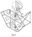
- Fig 6
- is a perspective view illustrating a rear rib of an air-plane fuselage according to fig 1 held in a fixed position with respect to a wall according to fig 2 connecting it to another rib.
- Fig 1 shows a part of a rear rib 1 of an airplane fuselage in the form of a first machine article to be secured to another,
second machine article 2 in the form of an intermediate wall shown in fig 2. The different members, such as reinforcingflanges 3, 3' and a lug portion 9, have been obtained from a single material piece through machining, here milling. This results in very small tolerances of the dimensions of these members. - A device for releasably holding the two
machine articles 1, 2 together in a mutually fixed position comprises afirst opening 5 in the first machine article 1 through which asecond lug portion 6 projecting from an end surface 7 of thesecond article 2 is designed to be moved from afirst side 8 of the first article, so that this end surface 7 bears tightly against saidfirst side 8. The first article has a first projecting lug portion 9 arranged on the oppositesecond side 10 of the first article adjacent to said first opening 5. - The two lug portions have an opening 11, 12 each passing therethrough transversely to said first opening 5 when the
second lug portion 6 is introduced through this opening. The opening 12 in the second lug portion is surroundingly delimited by lug portion walls, whereas the opening 11 of the first lug portion 9 is laterally opened in the direction away from the first article and by that groove-like. It is necessary that one of the two openings has surroundingly delimiting walls, and it is easier to accomplish this in the lug portion on the end surface than the lug portion arranged on a large surface of an article. Both lug portion openings may of course have surroundingly delimiting walls when desired. - The two lug portions are arranged to be located with their openings at least partially overlapping when the
second lug portion 6 is introduced through saidfirst opening 5. Furthermore, the respective lug portion opening is designed to have at least two surfaces defining it in alignment with corresponding surfaces defining the lug portion opening of the adjacent lug portion for defining said fixed position with respect to two dimensions, namely in a plane parallel tosurfaces 13 surrounding theopening 11 of the first lug portion 9 and here being perpendicular to the large surface 14 of the first article. Said surfaces to be in alignment are the bottom surface 15 of theopening 11 in the first lug portion 9, the correspondingsurface 16 in thesecond lug portion 6 and onesurface 17, 18 of each of these openings perpendicular thereto, in this case the upper surfaces as seen in fig 1 and 2. - The definition of said fixed position with respect to a third dimension is obtained by tightly bearing of the
surfaces 13 surrounding theopening 11 againstsurfaces 19 surrounding theopening 12 of the second lug portion when this is introduced through thefirst opening 5. - The device also comprises a
tool 20 illustrated in fig 3 and 4 adapted to hold the articles together in said mutually fixed position. How this is obtained is illustrated in fig 5. The tool has a wedge-shapedpart 21 adapted to be introduced through theopenings adjacent lug portions 6, 9 and press them into alignment of said definingsurfaces surfaces part 21 has a rectangular cross-section, in this case a square cross-section, with twoadjacent sides opposite side narrowest end 26 of thispart 21. The otheradjacent sides lower surface 27 of the first lug portion 9 and thelower surface 28 and thesurface 29 opposite to thesurface 16 of thesecond lug portion 6. - The wedge-shaped
part 21 has a threadedbore 30 extending therethrough. Afirst spacer 31 in the form of a sleeve is adapted to be applied upon the first lug portion around said mostnarrow end 26 of the wedge-shaped part when this is introduced through the lug portion openings and to be tightened against this lug portion by tightening ahead 33 of ascrew 32 engaging thebore 30 thereagainst. By tightening saidscrew 32 the wedge-shaped part is forced further through theopenings - The tool also comprises a
second spacer 34 also having a sleeve-like character to be applied on the second lug portion and tightened thereagainst by ascrew 35 engaging the threaded bore 30 from thethicker end 36 of the wedge-shapedpart 21 with thehead 37 of the screw against the spacer. By tightening thescrew 35 the wedge-shaped part will be influenced in the direction out of theopenings surfaces - The fixing of the two
articles 1, 2 in said mutually fixed position will take place in the following way. Thesecond lug portion 6 is firstly introduced through thefirst opening 5 of the first article 1, so that theopenings part 21 is then introduced with thenarrowest end 26 first through the two openings of the lug portions as shown in fig 5. Thefirst spacer 31 is after that applied onto the first lug portion and thescrew 32 introduced therethrough and through thebore 30 and tightened so as to pull the wedge-shapedpart 21 as much as possible through said openings of the lug portions for defining said fixed position into dimensions perpendicular to the direction of introduction of the wedge-shaped part. Thesecond spacer 34 is after that applied on the second lug portion and thescrew 35 is introduced therethrough and through thebore 30 and tightened for pressing thesurfaces - It is shown in fig 6 how the device also comprises means adapted to fix the two articles with respect to each other on a location at a distance from said tool, and this means is in this case a further such tool 20'. This tool 20' has only to fix the articles in two dimensions, namely in the direction of said introduction of the wedge-shaped part and in the direction of introduction of the second lug portion in the first opening of the first article. This means that the articles are prevented from rotating about the
first tool 20. - A number of such articles may in this way be mutually fixed and then in said fixed state be subjected to for instance drilling or broaching, application of sealing means and the like. The articles may then, still held in this state, be permanently secured to each other through for example riveting. Said
tools 20, 20' will after that be removed for being used when fixing other articles to each other. - The invention is not restricted to the embodiment shown in the figures and described above.
- The wedge-shaped part may for instance have another cross-section than that shown and the surfaces of the lug portion openings to be aligned be otherwise directed than shown.
- The inclined surfaces of the lug portion openings may be inclined in the other direction and the wedge-shaped part be introduced firstly through the first lug portion and then through the second lug portion. Thus, the first spacer will then bear against the second lug portion and the second against the first.
Claims (17)
- A system comprising two articles and a device for releasably holding the two articles together in a mutually fixed position, wherein the articles are machine articles, a first (1) of said articles is provided with at least one first opening (5), the other second article (2) is provided with at least a second projecting lug portion (6) designed to be moved through said opening in the first article from a first side (8) thereof, characterized in that at least a first projecting lug portion (9) is arranged on the opposite second side (10) of the first article adjacent to said opening, that the two lug portions have an opening (11, 12) each passing therethrough transversely to the first opening in the first article when said second lug portion (6) is introduced through this opening, that at least one of the lug portion openings is surroundingly delimited by lug portion walls, that the lug portions (6, 9) are arranged to be located with their openings (11, 12) at least partially overlapping when the second lug portion is introduced through said first opening, that the respective lug portion opening is designed to have at least two surfaces (15, 17) defining it in alignment with corresponding surfaces (16, 18) defining the lug portion opening of the adjacent lug portion for defining said fixed position with respect to two dimensions and the first lug portion has surfaces (13) surrounding said opening adapted to define said fixed position with respect to a third dimension by bearing against corresponding surfaces (19) of the second lug portion, and that it further comprises a tool (20) adapted to be introduced through the openings of adjacent lug portions and press them into alignment of said defining surfaces and said surrounding surfaces to bear under pretension against each other for holding the articles in a mutually fixed position.
- A device according to claim 1, characterized in that only one (6) of said two lug portions having delimiting surfaces to be moved into alignment has an opening surroundingly delimited by lug portion walls and the opening of the other lug portion (9) is laterally opened in the direction away from said first article in said fixed position and by that groove-like.
- A device according to claim 2, characterized in that said first lug portion (9) has a said groove-like opening (11).
- A device according to any of the preceding claims, characterized in that said tool (20) has a wedge-like character so as to through wedge action obtain said pressing into alignment of said delimiting surfaces (15-18) to each other in said fixed position.
- A device according to claim 4, characterized in that the tool (20) has an wedge-shaped part (21) adapted to have the most narrow end (26) thereof firstly introduced through said two openings of adjacent lug portions, and that the tool comprises means (30-32) for engagement with the most narrow end of the wedge-shaped part for applying a force thereon for pressing this part in the direction of said introduction.
- A device according to claim 5, characterized in that said means comprises a threaded bore (30) in the wedge-shaped part (21) extending in the longitudinal direction thereof from said most narrow end and a threaded male member (32) introducible into the bore and through a spacer (31) having a fixed minimum distance of a head (33) or the like thereof to one of said lug portions (9) so as to force the wedge-shaped part further through the openings when tightening the threaded male member.
- A device according to claim 5 or 6, characterized in that the tool (20) further comprises a member to be engaged with a thicker end (36) of the wedge-shaped part (21) not possible to be brought through the openings of the lug portions so as to apply forces on the wedge-shaped part in the opposite direction to the direction of introduction and by that press said surrounding surfaces (13, 19) of the two lug portions to bear against each other.
- A device according to claim 7, characterized in that the wedge-shaped part (21) has a threaded bore (30) extending substantially in the longitudinal direction thereof and opening in said thicker end (36), and that said member comprises a threaded male member (35) introducible into the bore and through a spacer (34) having a fixed minimum distance of a head (37) or the like thereof to one of said lug portions so as to act upon the wedge-shaped part in the direction out of the openings and by that press said surrounding surfaces (13, 19) of the lug portions against each other.
- A device according to any of claims 4-8, characterized in that the tool has a wedge-shaped part (21) to be introduced through the two openings (11, 12) of two adjacent lug portions in the direction of the most narrow end thereof, and that the wedge-shaped part has a substantially rectangular cross-section as seen in the direction of the introduction intended.
- A device according to claim 9, characterized in that two adjacent sides (22, 23) of the wedge-shaped part converges towards the respective opposite side in the direction towards the most narrow end of said part, while the two other adjacent sides (24 ,25) thereof extend substantially in parallel with said direction, and that delimiting surfaces of each opening in said lug portions are correspondingly inclined for tightly bearing against the two sides first mentioned of the wedge-shaped part thereagainst.
- A device according to any of the preceding claims, characterized in that it has means (20') adapted to fix the two articles with respect to each other on a location at a distance from said tool (20) for preventing the articles held together to rotate about said tool.
- A device according to claim 11, characterized in that said fixing means comprises a further said tool (20') adapted to co-operate in the same way as the tool first mentioned with lug portions and openings of the articles on said location.
- A method for releasably securing two articles in a mutually fixed position to each other, whereby it is carried out for securing articles in the form of machine articles and characterized in thata) a second (2) of the articles is moved with a second lug portion (6) projecting therefrom and provided with an opening (12) through a first opening (5) of a first article (1) also provided with a lug portion (9) having an opening (11), so that the openings of said lug portions are at least partially overlapping, said opening of at least one of the lug portions being surroundingly limited by lug portion walls,
the respective lug portion opening being designed to have at least two surfaces (15, 17) defining it in alignment with corresponding surfaces (16, 18) defining the lug portion opening of the adjacent lug portion for defining said fixed position with respect to two dimensions and the first lug portion having surfaces (13) surrounding said opening adapted to define said fixed position with respect to a third dimension by bearing against corresponding surfaces (19) of the second lug portion, andb) introducing a tool (20) through the openings of adjacent lug portions and pressing these into alignment of said defining surfaces and said surrounding surfaces to bear under pretension against each other for holding the articles in a mutually fixed position. - A method for permanently securing at least two articles to each other, in which the articles are brought into a mutually fixed position and are while holding them in this position permanently secured to each other, characterized in that it is carried out for securing articles in the form of machine articles anda) a second (2) of the articles is moved with a second lug portion (6) projecting therefrom and provided with an opening (12) through a first opening (5) of a first article (1) also provided with a lug portion (9) having an opening (11), so that the openings of said lug portions are at least partially overlapping, said opening of at least one of the lug portions being surroundingly limited by lug portion walls,
the respective lug portion opening being designed to have at least two surfaces (15, 17) defining it in alignment with corresponding surfaces (16, 18) defining the lug portion opening of the adjacent lug portion for defining said fixed position with respect to two dimensions and the first lug portion having surfaces (13) surrounding said opening adapted to define said fixed position with respect to a third dimension by bearing against corresponding surfaces (19) of the second lug portion,b) introducing a tool (20) through the openings of adjacent lug portions and pressing these into alignment of said defining surfaces and said surrounding surfaces to bear under pretension against each other for holding the articles in a mutually fixed position, andc) the articles are then in this fixed position permanently secured to each other, for example by riveting. - A method according to claim 14, characterized in that while holding the articles together in said mutually fixed position material removing machining of the articles is carried out, such as drilling and broaching, and that the articles are thereafter permanently secured to each other while maintaining them in said mutually fixed position.
- A method according to any of claims 13-15, characterized in that in step b) a tool (20) having a wedge-shaped part (21) is introduced with the most narrow end (26) of said part first through the two openings of adjacent lug portions, a threaded male member (32) is then introduced into a threaded bore (30) in the most narrow end of said wedge-shaped part from the opposite direction and is tightened with a head (33) or the like thereof against a spacer (31) defining a minimum distance of said head or the like to one of said lug portions so as to pull the wedge-shaped part further through said openings, another threaded male member (35) is after that introduced into a threaded bore (30) in the thicker end (36) of the wedge-shaped part for being tightened with a head (37) or the like thereof against a spacer (34) defining a minimum distance of said head or the like to the other lug portion for acting upon the wedge-shaped part in the direction out of the openings and by that press said surrounding surfaces of the lug portions against each other.
- A method according to any of claims 13-16, characterized in that it is carried out for securing articles of an airplane fuselage in a mutually fixed position.
Priority Applications (6)
| Application Number | Priority Date | Filing Date | Title |
|---|---|---|---|
| AT04018661T ATE350590T1 (en) | 2004-08-06 | 2004-08-06 | DEVICE AND METHOD FOR RESOLVABLY HOLDING TWO PARTS TOGETHER |
| EP04018661A EP1624200B1 (en) | 2004-08-06 | 2004-08-06 | A device and a method for releasably holding two articles together |
| ES04018661T ES2279261T3 (en) | 2004-08-06 | 2004-08-06 | DEVICE AND PROCEDURE FOR RETAINING TWO ITEMS MUTUALLY REMOVABLE. |
| DE602004004103T DE602004004103T2 (en) | 2004-08-06 | 2004-08-06 | Apparatus and method for releasably holding two parts together |
| US11/161,085 US20060029464A1 (en) | 2004-08-06 | 2005-07-22 | A device and a method for releasably holding two articles together |
| US11/773,416 US20080005879A1 (en) | 2004-08-06 | 2007-07-04 | Method for releasably holding two articles together |
Applications Claiming Priority (1)
| Application Number | Priority Date | Filing Date | Title |
|---|---|---|---|
| EP04018661A EP1624200B1 (en) | 2004-08-06 | 2004-08-06 | A device and a method for releasably holding two articles together |
Publications (2)
| Publication Number | Publication Date |
|---|---|
| EP1624200A1 EP1624200A1 (en) | 2006-02-08 |
| EP1624200B1 true EP1624200B1 (en) | 2007-01-03 |
Family
ID=34926076
Family Applications (1)
| Application Number | Title | Priority Date | Filing Date |
|---|---|---|---|
| EP04018661A Not-in-force EP1624200B1 (en) | 2004-08-06 | 2004-08-06 | A device and a method for releasably holding two articles together |
Country Status (5)
| Country | Link |
|---|---|
| US (2) | US20060029464A1 (en) |
| EP (1) | EP1624200B1 (en) |
| AT (1) | ATE350590T1 (en) |
| DE (1) | DE602004004103T2 (en) |
| ES (1) | ES2279261T3 (en) |
Families Citing this family (1)
| Publication number | Priority date | Publication date | Assignee | Title |
|---|---|---|---|---|
| CN104939806B (en) * | 2008-05-20 | 2021-12-10 | 大学健康网络 | Apparatus and method for fluorescence-based imaging and monitoring |
Family Cites Families (8)
| Publication number | Priority date | Publication date | Assignee | Title |
|---|---|---|---|---|
| US682144A (en) * | 1899-08-02 | 1901-09-03 | James H Higgins | Coal-pick. |
| US1917431A (en) * | 1928-12-22 | 1933-07-11 | American Manganese Steel Co | Excavating tooth base with laterally interlocked points |
| US2207359A (en) * | 1938-02-28 | 1940-07-09 | Wilfrid G Torrance | Toolholder |
| US3019537A (en) * | 1959-01-06 | 1962-02-06 | American Brake Shoe Co | Keeper for an excavator tooth |
| FR2513290A1 (en) * | 1981-09-24 | 1983-03-25 | Ciotat Chantiers Navals | TUBULAR TYPE SCAFFOLDS, METHOD OF MOUNTING AND HORIZONTAL CROSSINGS OF THESE SCAFFOLDS |
| US4625820A (en) * | 1985-04-09 | 1986-12-02 | Kidde, Inc. | Crawler frame to base frame connection |
| US4892435A (en) * | 1989-02-06 | 1990-01-09 | Grumman Aerospace Corporation | Interlocking structural members employing transverse locking double interfitting wedge |
| US5560102A (en) * | 1992-10-13 | 1996-10-01 | The Boeing Company | Panel and fuselage assembly |
-
2004
- 2004-08-06 ES ES04018661T patent/ES2279261T3/en active Active
- 2004-08-06 EP EP04018661A patent/EP1624200B1/en not_active Not-in-force
- 2004-08-06 DE DE602004004103T patent/DE602004004103T2/en not_active Expired - Fee Related
- 2004-08-06 AT AT04018661T patent/ATE350590T1/en not_active IP Right Cessation
-
2005
- 2005-07-22 US US11/161,085 patent/US20060029464A1/en not_active Abandoned
-
2007
- 2007-07-04 US US11/773,416 patent/US20080005879A1/en not_active Abandoned
Also Published As
| Publication number | Publication date |
|---|---|
| US20060029464A1 (en) | 2006-02-09 |
| US20080005879A1 (en) | 2008-01-10 |
| ATE350590T1 (en) | 2007-01-15 |
| ES2279261T3 (en) | 2007-08-16 |
| EP1624200A1 (en) | 2006-02-08 |
| DE602004004103T2 (en) | 2007-07-05 |
| DE602004004103D1 (en) | 2007-02-15 |
Similar Documents
| Publication | Publication Date | Title |
|---|---|---|
| US6105951A (en) | Work positioning jigs for machine tools | |
| JP6114290B2 (en) | Mechanically interlocking frame assembly | |
| US5664793A (en) | Quick-change chuck jaws | |
| EP3602708B1 (en) | Arrangement of a frame of an electrical cabinet and a base | |
| US5988930A (en) | Connecting apparatus for profile members | |
| EP0890418A2 (en) | Quick change jaw plate | |
| DE102010047380B3 (en) | Linear mechanical quick release | |
| US10953475B2 (en) | Chip/dust prevention cover, chip/dust prevention cover set, chuck mechanism, and machine tool | |
| US5857506A (en) | Replaceable insert cutting tools | |
| EP3363569B1 (en) | Clamping or gripping device | |
| EP1624200B1 (en) | A device and a method for releasably holding two articles together | |
| US5624106A (en) | Gripping device | |
| EP3756820B1 (en) | Zero point clamping system for machine tools, especially rotary and / or milling machines | |
| EP0502899A1 (en) | A device for releasable connection of two members. | |
| US4789191A (en) | Centering device for securing and centering a door handle | |
| US5888028A (en) | Tool holder | |
| US9733057B2 (en) | Blind hole location tool | |
| EP1334803B1 (en) | Clamping device, in particular a vice | |
| US4921167A (en) | Carrier section including flange member for connection to a guide rail | |
| GB2300031A (en) | Retainer for a blind rivet nut assembly | |
| EP0900628B1 (en) | Quick fitting system | |
| US6142042A (en) | Attaching-detaching tool | |
| AU2012351487B2 (en) | Heat sink mounting apparatus and method | |
| US20060261713A1 (en) | Tool platform | |
| FI97163B (en) | Device for fastening a bodywork nut |
Legal Events
| Date | Code | Title | Description |
|---|---|---|---|
| PUAI | Public reference made under article 153(3) epc to a published international application that has entered the european phase |
Free format text: ORIGINAL CODE: 0009012 |
|
| AK | Designated contracting states |
Kind code of ref document: A1 Designated state(s): AT BE BG CH CY CZ DE DK EE ES FI FR GB GR HU IE IT LI LU MC NL PL PT RO SE SI SK TR |
|
| AX | Request for extension of the european patent |
Extension state: AL HR LT LV MK |
|
| 17P | Request for examination filed |
Effective date: 20060307 |
|
| GRAP | Despatch of communication of intention to grant a patent |
Free format text: ORIGINAL CODE: EPIDOSNIGR1 |
|
| AKX | Designation fees paid |
Designated state(s): AT BE BG CH CY CZ DE DK EE ES FI FR GB GR HU IE IT LI LU MC NL PL PT RO SE SI SK TR |
|
| GRAS | Grant fee paid |
Free format text: ORIGINAL CODE: EPIDOSNIGR3 |
|
| GRAA | (expected) grant |
Free format text: ORIGINAL CODE: 0009210 |
|
| AK | Designated contracting states |
Kind code of ref document: B1 Designated state(s): AT BE BG CH CY CZ DE DK EE ES FI FR GB GR HU IE IT LI LU MC NL PL PT RO SE SI SK TR |
|
| PG25 | Lapsed in a contracting state [announced via postgrant information from national office to epo] |
Ref country code: LI Free format text: LAPSE BECAUSE OF FAILURE TO SUBMIT A TRANSLATION OF THE DESCRIPTION OR TO PAY THE FEE WITHIN THE PRESCRIBED TIME-LIMIT Effective date: 20070103 Ref country code: FI Free format text: LAPSE BECAUSE OF FAILURE TO SUBMIT A TRANSLATION OF THE DESCRIPTION OR TO PAY THE FEE WITHIN THE PRESCRIBED TIME-LIMIT Effective date: 20070103 Ref country code: PL Free format text: LAPSE BECAUSE OF FAILURE TO SUBMIT A TRANSLATION OF THE DESCRIPTION OR TO PAY THE FEE WITHIN THE PRESCRIBED TIME-LIMIT Effective date: 20070103 Ref country code: SI Free format text: LAPSE BECAUSE OF FAILURE TO SUBMIT A TRANSLATION OF THE DESCRIPTION OR TO PAY THE FEE WITHIN THE PRESCRIBED TIME-LIMIT Effective date: 20070103 Ref country code: CH Free format text: LAPSE BECAUSE OF FAILURE TO SUBMIT A TRANSLATION OF THE DESCRIPTION OR TO PAY THE FEE WITHIN THE PRESCRIBED TIME-LIMIT Effective date: 20070103 Ref country code: NL Free format text: LAPSE BECAUSE OF FAILURE TO SUBMIT A TRANSLATION OF THE DESCRIPTION OR TO PAY THE FEE WITHIN THE PRESCRIBED TIME-LIMIT Effective date: 20070103 Ref country code: DK Free format text: LAPSE BECAUSE OF FAILURE TO SUBMIT A TRANSLATION OF THE DESCRIPTION OR TO PAY THE FEE WITHIN THE PRESCRIBED TIME-LIMIT Effective date: 20070103 Ref country code: AT Free format text: LAPSE BECAUSE OF FAILURE TO SUBMIT A TRANSLATION OF THE DESCRIPTION OR TO PAY THE FEE WITHIN THE PRESCRIBED TIME-LIMIT Effective date: 20070103 |
|
| REG | Reference to a national code |
Ref country code: GB Ref legal event code: FG4D |
|
| REF | Corresponds to: |
Ref document number: 602004004103 Country of ref document: DE Date of ref document: 20070215 Kind code of ref document: P |
|
| REG | Reference to a national code |
Ref country code: IE Ref legal event code: FG4D |
|
| PG25 | Lapsed in a contracting state [announced via postgrant information from national office to epo] |
Ref country code: SE Free format text: LAPSE BECAUSE OF FAILURE TO SUBMIT A TRANSLATION OF THE DESCRIPTION OR TO PAY THE FEE WITHIN THE PRESCRIBED TIME-LIMIT Effective date: 20070403 |
|
| PG25 | Lapsed in a contracting state [announced via postgrant information from national office to epo] |
Ref country code: BG Free format text: LAPSE BECAUSE OF FAILURE TO SUBMIT A TRANSLATION OF THE DESCRIPTION OR TO PAY THE FEE WITHIN THE PRESCRIBED TIME-LIMIT Effective date: 20070404 |
|
| PG25 | Lapsed in a contracting state [announced via postgrant information from national office to epo] |
Ref country code: PT Free format text: LAPSE BECAUSE OF FAILURE TO SUBMIT A TRANSLATION OF THE DESCRIPTION OR TO PAY THE FEE WITHIN THE PRESCRIBED TIME-LIMIT Effective date: 20070604 |
|
| NLV1 | Nl: lapsed or annulled due to failure to fulfill the requirements of art. 29p and 29m of the patents act | ||
| REG | Reference to a national code |
Ref country code: CH Ref legal event code: PL |
|
| ET | Fr: translation filed | ||
| REG | Reference to a national code |
Ref country code: ES Ref legal event code: FG2A Ref document number: 2279261 Country of ref document: ES Kind code of ref document: T3 |
|
| PLBE | No opposition filed within time limit |
Free format text: ORIGINAL CODE: 0009261 |
|
| STAA | Information on the status of an ep patent application or granted ep patent |
Free format text: STATUS: NO OPPOSITION FILED WITHIN TIME LIMIT |
|
| PG25 | Lapsed in a contracting state [announced via postgrant information from national office to epo] |
Ref country code: SK Free format text: LAPSE BECAUSE OF FAILURE TO SUBMIT A TRANSLATION OF THE DESCRIPTION OR TO PAY THE FEE WITHIN THE PRESCRIBED TIME-LIMIT Effective date: 20070103 |
|
| 26N | No opposition filed |
Effective date: 20071005 |
|
| PG25 | Lapsed in a contracting state [announced via postgrant information from national office to epo] |
Ref country code: RO Free format text: LAPSE BECAUSE OF FAILURE TO SUBMIT A TRANSLATION OF THE DESCRIPTION OR TO PAY THE FEE WITHIN THE PRESCRIBED TIME-LIMIT Effective date: 20070103 Ref country code: CZ Free format text: LAPSE BECAUSE OF FAILURE TO SUBMIT A TRANSLATION OF THE DESCRIPTION OR TO PAY THE FEE WITHIN THE PRESCRIBED TIME-LIMIT Effective date: 20070103 Ref country code: BE Free format text: LAPSE BECAUSE OF FAILURE TO SUBMIT A TRANSLATION OF THE DESCRIPTION OR TO PAY THE FEE WITHIN THE PRESCRIBED TIME-LIMIT Effective date: 20070103 |
|
| PG25 | Lapsed in a contracting state [announced via postgrant information from national office to epo] |
Ref country code: GR Free format text: LAPSE BECAUSE OF FAILURE TO SUBMIT A TRANSLATION OF THE DESCRIPTION OR TO PAY THE FEE WITHIN THE PRESCRIBED TIME-LIMIT Effective date: 20070404 Ref country code: MC Free format text: LAPSE BECAUSE OF NON-PAYMENT OF DUE FEES Effective date: 20070831 |
|
| PG25 | Lapsed in a contracting state [announced via postgrant information from national office to epo] |
Ref country code: IE Free format text: LAPSE BECAUSE OF NON-PAYMENT OF DUE FEES Effective date: 20070807 |
|
| PGFP | Annual fee paid to national office [announced via postgrant information from national office to epo] |
Ref country code: DE Payment date: 20080811 Year of fee payment: 5 Ref country code: ES Payment date: 20080827 Year of fee payment: 5 |
|
| PGFP | Annual fee paid to national office [announced via postgrant information from national office to epo] |
Ref country code: FR Payment date: 20080731 Year of fee payment: 5 Ref country code: IT Payment date: 20080822 Year of fee payment: 5 |
|
| PGFP | Annual fee paid to national office [announced via postgrant information from national office to epo] |
Ref country code: GB Payment date: 20080811 Year of fee payment: 5 |
|
| PG25 | Lapsed in a contracting state [announced via postgrant information from national office to epo] |
Ref country code: EE Free format text: LAPSE BECAUSE OF FAILURE TO SUBMIT A TRANSLATION OF THE DESCRIPTION OR TO PAY THE FEE WITHIN THE PRESCRIBED TIME-LIMIT Effective date: 20070103 |
|
| PG25 | Lapsed in a contracting state [announced via postgrant information from national office to epo] |
Ref country code: CY Free format text: LAPSE BECAUSE OF FAILURE TO SUBMIT A TRANSLATION OF THE DESCRIPTION OR TO PAY THE FEE WITHIN THE PRESCRIBED TIME-LIMIT Effective date: 20070103 |
|
| PG25 | Lapsed in a contracting state [announced via postgrant information from national office to epo] |
Ref country code: LU Free format text: LAPSE BECAUSE OF NON-PAYMENT OF DUE FEES Effective date: 20070806 |
|
| PG25 | Lapsed in a contracting state [announced via postgrant information from national office to epo] |
Ref country code: HU Free format text: LAPSE BECAUSE OF FAILURE TO SUBMIT A TRANSLATION OF THE DESCRIPTION OR TO PAY THE FEE WITHIN THE PRESCRIBED TIME-LIMIT Effective date: 20070704 Ref country code: TR Free format text: LAPSE BECAUSE OF FAILURE TO SUBMIT A TRANSLATION OF THE DESCRIPTION OR TO PAY THE FEE WITHIN THE PRESCRIBED TIME-LIMIT Effective date: 20070103 |
|
| GBPC | Gb: european patent ceased through non-payment of renewal fee |
Effective date: 20090806 |
|
| REG | Reference to a national code |
Ref country code: FR Ref legal event code: ST Effective date: 20100430 |
|
| PG25 | Lapsed in a contracting state [announced via postgrant information from national office to epo] |
Ref country code: FR Free format text: LAPSE BECAUSE OF NON-PAYMENT OF DUE FEES Effective date: 20090831 Ref country code: DE Free format text: LAPSE BECAUSE OF NON-PAYMENT OF DUE FEES Effective date: 20100302 |
|
| REG | Reference to a national code |
Ref country code: ES Ref legal event code: FD2A Effective date: 20090807 |
|
| PG25 | Lapsed in a contracting state [announced via postgrant information from national office to epo] |
Ref country code: GB Free format text: LAPSE BECAUSE OF NON-PAYMENT OF DUE FEES Effective date: 20090806 |
|
| PG25 | Lapsed in a contracting state [announced via postgrant information from national office to epo] |
Ref country code: IT Free format text: LAPSE BECAUSE OF NON-PAYMENT OF DUE FEES Effective date: 20090806 |
|
| PG25 | Lapsed in a contracting state [announced via postgrant information from national office to epo] |
Ref country code: ES Free format text: LAPSE BECAUSE OF NON-PAYMENT OF DUE FEES Effective date: 20090807 |