EP1624096B1 - Device for weaving the trimmings of a fabric produced by means of shuttleless weaving machines - Google Patents
Device for weaving the trimmings of a fabric produced by means of shuttleless weaving machines Download PDFInfo
- Publication number
- EP1624096B1 EP1624096B1 EP20050107086 EP05107086A EP1624096B1 EP 1624096 B1 EP1624096 B1 EP 1624096B1 EP 20050107086 EP20050107086 EP 20050107086 EP 05107086 A EP05107086 A EP 05107086A EP 1624096 B1 EP1624096 B1 EP 1624096B1
- Authority
- EP
- European Patent Office
- Prior art keywords
- weaving
- threads
- trimmings
- satellites
- yarn
- Prior art date
- Legal status (The legal status is an assumption and is not a legal conclusion. Google has not performed a legal analysis and makes no representation as to the accuracy of the status listed.)
- Not-in-force
Links
Images


Classifications
-
- D—TEXTILES; PAPER
- D03—WEAVING
- D03C—SHEDDING MECHANISMS; PATTERN CARDS OR CHAINS; PUNCHING OF CARDS; DESIGNING PATTERNS
- D03C7/00—Leno or similar shedding mechanisms
- D03C7/08—Devices for twisting warp threads repeatedly in the same direction
Definitions
- the present invention relates to a device for weaving the trimmings of a fabric produced by means of shuttleless weaving machines.
- the weaving of the side trimmings of a fabric must be effected by interlacing the warp and weft threads so as to prevent the side warp threads from becoming unthreaded from the weft threads.
- slotted leno heald consists in controlling the position of a pair of threads to form a so-called "warp mouth", similar to that of the other warp threads, by inverting the reciprocal position for each, or more, weft insertion(s).
- a first type of traditional device uses, in particular, a disk with two holes through which the weaving threads pass, wherein the disk is placed parallel to the threads in order to effect the weaving.
- This device however, has the drawback of vertical encumbrance, which prevents the device itself from being housed inside the doup-heald frame, thus limiting the maximum number of installable frames.
- a further disadvantage lies in the fact that as the disk holes run in a circular path, they scrape the weaving threads with the consequent risk of damage due to wear.
- rotating splitz The most commonly used devices for weaving the trimmings of a fabric are called "rotating splitz" and are based on an epicycloid gearing having the reserves of the two weaving threads installed on board.
- US-A-5 392 819 discloses a device for weaving the trimmings of a fabric produced by weaving machines according to the preamble of claim 1.
- An objective of the present invention is to overcome the above drawbacks and, in particular, to provide a device for weaving the trimmings of a fabric produced by weaving machines, which reduces the overall encumbrance of the system, regardless of the dimensions of the yarn packs used, which are situated outside the device itself.
- Another objective of the invention is to provide a device for weaving the trimmings of a fabric produced by weaving machines, which allows the efficient control of the thread opening, so as to obtain the same opening angle of the upper and lower thread, thus nullify-ing/minimizing the sliding between the threads in the feeding tract between the yarn packs and the device itself.
- a further objective of the invention is to provide a device for weaving the trimmings of a fabric produced by weaving machines, which allows the percentage elongation of the threads in the shed opening to be reduced.
- An additional objective of the invention is to provide a device for weaving the trimmings of a fabric in a simple, fast, precise, economical and reliable way.
- the present invention retains the technical properties of the epicycloid gearings ("rotating splitz") of the known type, it overcomes encumbrance problems and, with respect to all the traditional systems, reduces the percentage elongation of the threads, in the shed opening.
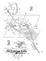
- 1 generically indicates a device with an epicycloid gearing of the known type, comprising, inside a shaped support 10, a circular plate 11, made to rotate by known means, along the direction of the arrow F in figure 1 , so as to distribute the rotatory movement to two satellites 13, each of which is connected to the relative weaving thread 4, 4A.
- the yarns 4, 4A are guided into the device 1 through the duct 14 of the supporting element 15 and from there to the centre of the plate 11, inside the shaped hole 16.
- the weaving threads 4, 4A are then split and passed through the central openings 17, 18 ( fig. 1 ) of the satellites 13 and subsequently deviated inside the eyelets 8, in turn assembled on suitable brackets 19, 20, until they converge in correspondence with the path 21, which represents the weaving points 22 of the selvedge 23 of the fabric produced, the latter generically marked with 24.
- Both the eyelets 8 are positioned eccentrically with respect to the relevant axis 6 ( fig. 3 ) of each satellite 13, so that the above eyelets 8 follow elliptical paths.
- the spools, marked with 2 in figure 1 , of the weaving threads 4 and 4A are positioned on an external support 9, rotating along the direction of the arrow G of figure 1 , and the threads 4 and 4A enter the epicycloid device 1, first at the center of the plate 11, near the revolution axis 5 of the satellites 13, and then to the centre of the respective satellites 13, close to the relative rotation axes 6.
- the device can operate according to two different modes, with the support 9 in synchronous rotation with the rotating plate 11, when the latter rotates in a single direction, in order to avoid an accumulation of the intertwining of the threads 4, 4A with each other, in the tract between the interception 3 and the device 1, or with the support 9 fixed, when the rotating plate 11 is rotated alternately for a certain number of rounds in the two opposite directions, maintaining the intertwining of the weaving threads 4, 4A in the tract existing between the interception 3 and the device 1, on an average null.
- the reduction in the elongation of the threads 4, 4A is due to the fact that the "splitz" with epicycloid gearings, such as that used in the present invention, does not also form a shed at the thread feeding side and distributes the elongation caused by the anterior warp shed (in correspondence with the formation side of the fabric 24) on a thread length extended to the packs 2 of yarn.
- the device described is capable of maintaining the opening angles of the yarn, marked by ⁇ and ⁇ in figure 1 , almost equal in all phases, by optimising the opening of the weaving threads 4, 4A and minimizing the respective sliding of the threads 4, 4A in the feeding zone, particularly in the operating mode with a fixed support 9 of the yarn packs 2.
- the use of the device according to the invention causes a trend of the thread opening angle in the upper part (angle ⁇ ) and in the lower part (angle ⁇ ) which practically follows a sinusoidal law, if a constant rotation rate of the rotating plate 11 is established.
Landscapes
- Engineering & Computer Science (AREA)
- Textile Engineering (AREA)
- Looms (AREA)
Description
- The present invention relates to a device for weaving the trimmings of a fabric produced by means of shuttleless weaving machines.
- As is known, the weaving of the side trimmings of a fabric must be effected by interlacing the warp and weft threads so as to prevent the side warp threads from becoming unthreaded from the weft threads.
- The most widely used weaving method, called slotted leno heald, consists in controlling the position of a pair of threads to form a so-called "warp mouth", similar to that of the other warp threads, by inverting the reciprocal position for each, or more, weft insertion(s).
- Various devices are known which can effect this interlacing.
- A first type of traditional device uses, in particular, a disk with two holes through which the weaving threads pass, wherein the disk is placed parallel to the threads in order to effect the weaving.
- This device, however, has the drawback of vertical encumbrance, which prevents the device itself from being housed inside the doup-heald frame, thus limiting the maximum number of installable frames.
- A further disadvantage lies in the fact that as the disk holes run in a circular path, they scrape the weaving threads with the consequent risk of damage due to wear.
- Other types of devices are proposed for solving the problem of vertical encumbrance and can be positioned inside the doup-heald frames, but still have drawbacks, among which the possibility of causing excessive sliding between the guiding eyelets and the threads and/or excessive transversal encumbrance, which limits the maximum weaving height of the machine.
- The most commonly used devices for weaving the trimmings of a fabric are called "rotating splitz" and are based on an epicycloid gearing having the reserves of the two weaving threads installed on board.
- These devices represent a good compromise from the point of view of controlling the opening angle of the weaving threads (which, in practice, follows a sinusoidal law, if a constant rotation rate of the gearing is imposed) and of the path (of the elliptical type) of the guiding eyelets of the threads.
- This type of device, however, has the problem of encumbrance, due to the fact that the thread feeding spools are assembled on the satellites of the epicycloid gearing of the device itself.
- This means that it is practically impossible to position the device inside the doup-heald frame, due to the encumbrance and this fact also limits the dimensions of the packs of yarn which feed the weaving threads.
-
US-A-5 392 819 discloses a device for weaving the trimmings of a fabric produced by weaving machines according to the preamble of claim 1. - An objective of the present invention is to overcome the above drawbacks and, in particular, to provide a device for weaving the trimmings of a fabric produced by weaving machines, which reduces the overall encumbrance of the system, regardless of the dimensions of the yarn packs used, which are situated outside the device itself.
- Another objective of the invention is to provide a device for weaving the trimmings of a fabric produced by weaving machines, which allows the efficient control of the thread opening, so as to obtain the same opening angle of the upper and lower thread, thus nullify-ing/minimizing the sliding between the threads in the feeding tract between the yarn packs and the device itself.
- A further objective of the invention is to provide a device for weaving the trimmings of a fabric produced by weaving machines, which allows the percentage elongation of the threads in the shed opening to be reduced.
- An additional objective of the invention is to provide a device for weaving the trimmings of a fabric in a simple, fast, precise, economical and reliable way.
- These objectives are achieved by producing a device for weaving the trimmings of a fabric produced by means of weaving machines according to claim 1.
- Other technical characteristics are indicated in the following claims.
- Advantageously, the present invention retains the technical properties of the epicycloid gearings ("rotating splitz") of the known type, it overcomes encumbrance problems and, with respect to all the traditional systems, reduces the percentage elongation of the threads, in the shed opening.
- Further characteristics and advantages of a device for weaving the trimmings of a fabric produced by means of weaving machines will appear more evident from the following description and enclosed figures, which are provided for illustrative and non-limiting purposes, in which:
-
figure 1 shows a complete perspective view of the device for weaving the trimmings, object of the present invention; -
figure 2 is a perspective view illustrating the thread feeding side of the device shown infigure 1 ; -
figure 3 is a sectional view of the device offigure 1 , taken along the line III-III offigure 1 ; -
figure 4 shows a Cartesian diagram of the trend of the opening angle of the thread near the selvedge weaving in relation to the rotation angle of the gearing offigure 1 . - With particular reference to
figures 1-3 , 1 generically indicates a device with an epicycloid gearing of the known type, comprising, inside ashaped support 10, acircular plate 11, made to rotate by known means, along the direction of the arrow F infigure 1 , so as to distribute the rotatory movement to twosatellites 13, each of which is connected to therelative weaving thread - In particular (
fig. 2 ), theyarns duct 14 of the supportingelement 15 and from there to the centre of theplate 11, inside theshaped hole 16. - The
weaving threads fig. 1 ) of thesatellites 13 and subsequently deviated inside theeyelets 8, in turn assembled onsuitable brackets path 21, which represents theweaving points 22 of theselvedge 23 of the fabric produced, the latter generically marked with 24. - Both the
eyelets 8 are positioned eccentrically with respect to the relevant axis 6 (fig. 3 ) of eachsatellite 13, so that theabove eyelets 8 follow elliptical paths. - In any case, the passage through the
eyelets 8, positioned eccentrically on thesatellites 13, is known art, as is also the weaving procedure. - According to the present invention, the spools, marked with 2 in
figure 1 , of theweaving threads external support 9, rotating along the direction of the arrow G offigure 1 , and thethreads plate 11, near therevolution axis 5 of thesatellites 13, and then to the centre of therespective satellites 13, close to therelative rotation axes 6. - The device can operate according to two different modes, with the
support 9 in synchronous rotation with therotating plate 11, when the latter rotates in a single direction, in order to avoid an accumulation of the intertwining of thethreads interception 3 and the device 1, or with thesupport 9 fixed, when therotating plate 11 is rotated alternately for a certain number of rounds in the two opposite directions, maintaining the intertwining of theweaving threads interception 3 and the device 1, on an average null. - The reduction in the elongation of the
threads - Finally, the device described is capable of maintaining the opening angles of the yarn, marked by α and β in
figure 1 , almost equal in all phases, by optimising the opening of theweaving threads threads fixed support 9 of the yarn packs 2. - In this case, unlike the known devices which have a delayed or anticipated opening angle of the thread with respect to a comparative sinusoidal law, depending on whether the thread is opened in the upper or lower part, (i.e. the angle α is different from the angle β in many of the operating phases of the device), as shown in the diagram of
figure 4 , the use of the device according to the invention causes a trend of the thread opening angle in the upper part (angle α) and in the lower part (angle β) which practically follows a sinusoidal law, if a constant rotation rate of the rotatingplate 11 is established. - From the above description the characteristics of the device for weaving the trimmings of a fabric produced by weaving machines, which is the objective of the present invention, as defined by the claims, are evident, as are also the relevant advantages.
- In particular they refer to the following aspects:
- reduction in the vertical and transversal encumbrance, also maintaining a sufficient opening angle of the weaving threads;
- minimum phenomena of sliding and of general damage to the weaving threads;
- efficient control of the opening angle of the weaving threads and of the path (of the elliptical type) of the guiding eyelets of the threads themselves.
- Finally, numerous other variations can obviously be applied to the device in question, all included in the invention, as defined by the claims. It is also evident that in the practical embodiment of the invention, as defined by the claims the materials, forms and dimensions of the details illustrated can vary according to the demands and can be substituted by other technically equivalent alternatives.
Claims (6)
- A device for weaving the trimmings (23) of a fabric (24) produced by weaving machines, comprising a device (1) with at least one satellite (13) epicycloid gearing, suitable for distributing two weaving threads (4, 4A) in correspondence with the points (22) of the fabric (24) where the weaving of the trimmings (23) is to be effected, wherein said weaving threads (4, 4A), connected to respective satellites (13), come from packs of yarn (2) arranged on at least one support (9) outside the device (1), characterised in that said support (9) of the yarn packs (2) rotates (G) in synchrony with said epicycloid gearing or, alternatively, said support (9) of the yarn packs (2) is stationary and said epicycloid gearing rotates alternately in one and in the opposite direction with programmable sequences.
- The device according to claim 1, characterised in that said epicycloid gearing comprises, inside a shaped support (10), a rotating (F) circular plate or disk (11), suitable for distributing the rotational movement to two satellites (13), said weaving threads (4, 4A) being arranged in pairs in the feeding tract and being guided into the device (1) in correspondence with said plate or disk (11).
- The device according to claim 2, characterised in that said weaving threads (4, 4A) are decoupled downstream of said plate or disk (11) and are deviated inside respective eyelets (8) present on each satellite (13), until they converge in correspondence with a path (21), which represents all the weaving points (22) of the selvedge (23) of the fabric (24).
- The device according to claim 3, characterised in that said eyelets (8) are positioned eccentrically with respect to the relative axis (6) of each satellite (13), so that said eyelets (8) follow an elliptic path.
- The device according to claim 2, characterised in that said weaving threads (4, 4A) are guided into the device (1), close to the revolution axis (5) of said satellites (13), and are then guided centrally, near the rotation axis (6) of said satellites (13).
- The device according to claim 1, characterised in that said device (1) maintains the opening angles (α, β) of the yarn, substantially equal in all phases, optimizing the opening of the weaving threads (4, 4A) and nullifying the relative sliding between the threads (4, 4A) in the areas where they can be intertwined.
Applications Claiming Priority (1)
| Application Number | Priority Date | Filing Date | Title |
|---|---|---|---|
| ITVI20040196 ITVI20040196A1 (en) | 2004-08-05 | 2004-08-05 | DEVICE FOR THE FORMATION OF THE BINDING OF THE EDGES OF A FABRIC PRODUCED WITH TEXTILE MACHINES WITHOUT SHUTTLE |
Publications (3)
| Publication Number | Publication Date |
|---|---|
| EP1624096A2 EP1624096A2 (en) | 2006-02-08 |
| EP1624096A3 EP1624096A3 (en) | 2007-07-04 |
| EP1624096B1 true EP1624096B1 (en) | 2010-02-17 |
Family
ID=35328843
Family Applications (1)
| Application Number | Title | Priority Date | Filing Date |
|---|---|---|---|
| EP20050107086 Not-in-force EP1624096B1 (en) | 2004-08-05 | 2005-08-01 | Device for weaving the trimmings of a fabric produced by means of shuttleless weaving machines |
Country Status (5)
| Country | Link |
|---|---|
| EP (1) | EP1624096B1 (en) |
| JP (1) | JP2006045762A (en) |
| CN (1) | CN1754997A (en) |
| DE (1) | DE602005019352D1 (en) |
| IT (1) | ITVI20040196A1 (en) |
Families Citing this family (7)
| Publication number | Priority date | Publication date | Assignee | Title |
|---|---|---|---|---|
| JP2007002385A (en) * | 2005-05-25 | 2007-01-11 | Tsudakoma Corp | Selvedge apparatus for loom |
| JP5184241B2 (en) * | 2008-07-25 | 2013-04-17 | 津田駒工業株式会社 | Planetary gear-type ear assembly device in a loom |
| CN109723763B (en) * | 2019-03-05 | 2021-11-23 | 杨新华 | Variable crank stroke opening device |
| EP3896201B1 (en) * | 2020-04-14 | 2023-06-07 | Picanol | Device for forming a leno weave in a weaving machine |
| CN111286839B (en) * | 2020-04-16 | 2024-07-26 | 山东玉马遮阳科技股份有限公司 | Weaving method of vertical flexible screen window curtain cloth |
| CN113913989A (en) * | 2021-11-16 | 2022-01-11 | 山东玉马遮阳科技股份有限公司 | Light control curtain and preparation method thereof |
| CN114717740B (en) * | 2022-03-15 | 2023-12-08 | 云路复合材料(上海)有限公司 | Magnetic force rail-changing braiding mechanism |
Family Cites Families (5)
| Publication number | Priority date | Publication date | Assignee | Title |
|---|---|---|---|---|
| NL7009073A (en) * | 1970-06-19 | 1971-12-21 | ||
| JPS5926544A (en) * | 1982-08-04 | 1984-02-10 | 日産自動車株式会社 | Twist tab weaving apparatus of loom |
| US5392819A (en) * | 1993-12-10 | 1995-02-28 | Hunshin Enterprise Co., Ltd. | Planetary gear type selvage forming and cord catching device for loom |
| JP3994559B2 (en) * | 1998-12-10 | 2007-10-24 | 株式会社豊田自動織機 | Ear forming device in loom |
| US6546966B2 (en) * | 2001-03-27 | 2003-04-15 | Sulzer Textil Ag | Apparatus for making available a leno thread for a weaving machine |
-
2004
- 2004-08-05 IT ITVI20040196 patent/ITVI20040196A1/en unknown
-
2005
- 2005-08-01 EP EP20050107086 patent/EP1624096B1/en not_active Not-in-force
- 2005-08-01 DE DE200560019352 patent/DE602005019352D1/en active Active
- 2005-08-05 CN CN 200510116584 patent/CN1754997A/en active Pending
- 2005-08-05 JP JP2005227840A patent/JP2006045762A/en active Pending
Also Published As
| Publication number | Publication date |
|---|---|
| EP1624096A3 (en) | 2007-07-04 |
| DE602005019352D1 (en) | 2010-04-01 |
| ITVI20040196A1 (en) | 2004-11-05 |
| JP2006045762A (en) | 2006-02-16 |
| EP1624096A2 (en) | 2006-02-08 |
| CN1754997A (en) | 2006-04-05 |
Similar Documents
| Publication | Publication Date | Title |
|---|---|---|
| EP1624096B1 (en) | Device for weaving the trimmings of a fabric produced by means of shuttleless weaving machines | |
| JP3278811B2 (en) | Apparatus for forming Leno ears, especially for shuttleless looms | |
| RU2239009C2 (en) | Shuttleless tape weaving machine for manufacture of narrow woven products and narrow woven product | |
| US5123454A (en) | Crossing device for the production of non-fraying edges of a double woven fabric on a double-rapier loom | |
| JP2006045762A5 (en) | ||
| KR100985574B1 (en) | Circular loom | |
| RU2004100539A (en) | WEAVING MACHINE FOR THE TRANSFERRING WEAVING FABRIC | |
| US11242626B2 (en) | Narrow fabric needle loom and corresponding weaving method | |
| EP1920094B1 (en) | Method and device for forming a leno fabric on a weaving machine | |
| EP1888826B1 (en) | Terry loom and backrest arrangement for a weaving machine | |
| KR20160029828A (en) | Weaving machine having a device for forming a leno selvedge | |
| RU2179206C2 (en) | Electric engine control system of interwoven edge forming device | |
| CN110168156B (en) | Selvage device | |
| EP1783254A1 (en) | Warp yarn weaving device for selvedge formation in weaving looms | |
| US20130333794A1 (en) | Device for manufacturing a fabric, and fabric | |
| JPS63135541A (en) | Circular loom | |
| CA3177707A1 (en) | Loom with movable guide beams | |
| US7451788B2 (en) | Apparatus and method for weaving leno fabric | |
| US5868173A (en) | Lifter device for a jacquard machine | |
| EP1179623B1 (en) | Device for forming the leno heald weave in weaving looms | |
| CN210215721U (en) | Weft yarn separating device | |
| US20190376213A1 (en) | Ribbon Needle Loom | |
| KR200265621Y1 (en) | Cam for circular weaving loom | |
| EP1726696A2 (en) | Selvage device in loom | |
| JPS62177256A (en) | Weft yarn insert channel of jet loom |
Legal Events
| Date | Code | Title | Description |
|---|---|---|---|
| PUAI | Public reference made under article 153(3) epc to a published international application that has entered the european phase |
Free format text: ORIGINAL CODE: 0009012 |
|
| AK | Designated contracting states |
Kind code of ref document: A2 Designated state(s): AT BE BG CH CY CZ DE DK EE ES FI FR GB GR HU IE IS IT LI LT LU LV MC NL PL PT RO SE SI SK TR |
|
| AX | Request for extension of the european patent |
Extension state: AL BA HR MK YU |
|
| PUAL | Search report despatched |
Free format text: ORIGINAL CODE: 0009013 |
|
| AK | Designated contracting states |
Kind code of ref document: A3 Designated state(s): AT BE BG CH CY CZ DE DK EE ES FI FR GB GR HU IE IS IT LI LT LU LV MC NL PL PT RO SE SI SK TR |
|
| AX | Request for extension of the european patent |
Extension state: AL BA HR MK YU |
|
| RIC1 | Information provided on ipc code assigned before grant |
Ipc: D03C 7/06 20060101AFI20051123BHEP Ipc: D03C 7/08 20060101ALI20070531BHEP |
|
| 17P | Request for examination filed |
Effective date: 20071129 |
|
| AKX | Designation fees paid |
Designated state(s): BE CH DE IT LI |
|
| 17Q | First examination report despatched |
Effective date: 20080326 |
|
| GRAP | Despatch of communication of intention to grant a patent |
Free format text: ORIGINAL CODE: EPIDOSNIGR1 |
|
| GRAS | Grant fee paid |
Free format text: ORIGINAL CODE: EPIDOSNIGR3 |
|
| GRAA | (expected) grant |
Free format text: ORIGINAL CODE: 0009210 |
|
| AK | Designated contracting states |
Kind code of ref document: B1 Designated state(s): BE CH DE IT LI |
|
| REG | Reference to a national code |
Ref country code: CH Ref legal event code: EP |
|
| REF | Corresponds to: |
Ref document number: 602005019352 Country of ref document: DE Date of ref document: 20100401 Kind code of ref document: P |
|
| PG25 | Lapsed in a contracting state [announced via postgrant information from national office to epo] |
Ref country code: BE Free format text: LAPSE BECAUSE OF FAILURE TO SUBMIT A TRANSLATION OF THE DESCRIPTION OR TO PAY THE FEE WITHIN THE PRESCRIBED TIME-LIMIT Effective date: 20100217 |
|
| PLBE | No opposition filed within time limit |
Free format text: ORIGINAL CODE: 0009261 |
|
| STAA | Information on the status of an ep patent application or granted ep patent |
Free format text: STATUS: NO OPPOSITION FILED WITHIN TIME LIMIT |
|
| 26N | No opposition filed |
Effective date: 20101118 |
|
| REG | Reference to a national code |
Ref country code: CH Ref legal event code: PL |
|
| PG25 | Lapsed in a contracting state [announced via postgrant information from national office to epo] |
Ref country code: CH Free format text: LAPSE BECAUSE OF NON-PAYMENT OF DUE FEES Effective date: 20100831 Ref country code: LI Free format text: LAPSE BECAUSE OF NON-PAYMENT OF DUE FEES Effective date: 20100831 |
|
| PG25 | Lapsed in a contracting state [announced via postgrant information from national office to epo] |
Ref country code: IT Free format text: LAPSE BECAUSE OF NON-PAYMENT OF DUE FEES Effective date: 20100801 |
|
| REG | Reference to a national code |
Ref country code: DE Ref legal event code: R119 Ref document number: 602005019352 Country of ref document: DE Effective date: 20110301 |
|
| PG25 | Lapsed in a contracting state [announced via postgrant information from national office to epo] |
Ref country code: DE Free format text: LAPSE BECAUSE OF NON-PAYMENT OF DUE FEES Effective date: 20110301 |