EP1623887A2 - Passenger protecting device - Google Patents
Passenger protecting device Download PDFInfo
- Publication number
- EP1623887A2 EP1623887A2 EP05016763A EP05016763A EP1623887A2 EP 1623887 A2 EP1623887 A2 EP 1623887A2 EP 05016763 A EP05016763 A EP 05016763A EP 05016763 A EP05016763 A EP 05016763A EP 1623887 A2 EP1623887 A2 EP 1623887A2
- Authority
- EP
- European Patent Office
- Prior art keywords
- bag
- protecting device
- disposed
- passenger protecting
- cover
- Prior art date
- Legal status (The legal status is an assumption and is not a legal conclusion. Google has not performed a legal analysis and makes no representation as to the accuracy of the status listed.)
- Granted
Links
- 239000004744 fabric Substances 0.000 description 88
- 238000010586 diagram Methods 0.000 description 12
- 239000000463 material Substances 0.000 description 12
- XLYOFNOQVPJJNP-UHFFFAOYSA-N water Substances O XLYOFNOQVPJJNP-UHFFFAOYSA-N 0.000 description 12
- 229920003002 synthetic resin Polymers 0.000 description 6
- 239000000057 synthetic resin Substances 0.000 description 6
- 239000002184 metal Substances 0.000 description 5
- 238000003466 welding Methods 0.000 description 5
- 210000000078 claw Anatomy 0.000 description 4
- 238000000034 method Methods 0.000 description 4
- 238000007789 sealing Methods 0.000 description 4
- 238000005299 abrasion Methods 0.000 description 2
- 238000001514 detection method Methods 0.000 description 2
- 230000006866 deterioration Effects 0.000 description 2
- 239000003651 drinking water Substances 0.000 description 2
- 235000020188 drinking water Nutrition 0.000 description 2
- 239000010813 municipal solid waste Substances 0.000 description 2
- 230000000452 restraining effect Effects 0.000 description 2
- 239000004576 sand Substances 0.000 description 2
- JOYRKODLDBILNP-UHFFFAOYSA-N Ethyl urethane Chemical compound CCOC(N)=O JOYRKODLDBILNP-UHFFFAOYSA-N 0.000 description 1
- 239000004743 Polypropylene Substances 0.000 description 1
- 230000001419 dependent effect Effects 0.000 description 1
- 238000007599 discharging Methods 0.000 description 1
- 230000000694 effects Effects 0.000 description 1
- 239000013013 elastic material Substances 0.000 description 1
- 230000005611 electricity Effects 0.000 description 1
- 239000004033 plastic Substances 0.000 description 1
- -1 polypropylene Polymers 0.000 description 1
- 229920001155 polypropylene Polymers 0.000 description 1
- 230000000717 retained effect Effects 0.000 description 1
- 238000004826 seaming Methods 0.000 description 1
- 210000000689 upper leg Anatomy 0.000 description 1
Images











Classifications
-
- B—PERFORMING OPERATIONS; TRANSPORTING
- B60—VEHICLES IN GENERAL
- B60R—VEHICLES, VEHICLE FITTINGS, OR VEHICLE PARTS, NOT OTHERWISE PROVIDED FOR
- B60R21/00—Arrangements or fittings on vehicles for protecting or preventing injuries to occupants or pedestrians in case of accidents or other traffic risks
- B60R21/02—Occupant safety arrangements or fittings, e.g. crash pads
- B60R21/16—Inflatable occupant restraints or confinements designed to inflate upon impact or impending impact, e.g. air bags
- B60R21/20—Arrangements for storing inflatable members in their non-use or deflated condition; Arrangement or mounting of air bag modules or components
- B60R21/207—Arrangements for storing inflatable members in their non-use or deflated condition; Arrangement or mounting of air bag modules or components in vehicle seats
-
- B—PERFORMING OPERATIONS; TRANSPORTING
- B60—VEHICLES IN GENERAL
- B60N—SEATS SPECIALLY ADAPTED FOR VEHICLES; VEHICLE PASSENGER ACCOMMODATION NOT OTHERWISE PROVIDED FOR
- B60N2/00—Seats specially adapted for vehicles; Arrangement or mounting of seats in vehicles
- B60N2/24—Seats specially adapted for vehicles; Arrangement or mounting of seats in vehicles for particular purposes or particular vehicles
- B60N2/42—Seats specially adapted for vehicles; Arrangement or mounting of seats in vehicles for particular purposes or particular vehicles the seat constructed to protect the occupant from the effect of abnormal g-forces, e.g. crash or safety seats
- B60N2/427—Seats or parts thereof displaced during a crash
- B60N2/42727—Seats or parts thereof displaced during a crash involving substantially rigid displacement
- B60N2/42754—Seats or parts thereof displaced during a crash involving substantially rigid displacement of the cushion
- B60N2/42763—Seats or parts thereof displaced during a crash involving substantially rigid displacement of the cushion with anti-submarining systems
-
- B—PERFORMING OPERATIONS; TRANSPORTING
- B60—VEHICLES IN GENERAL
- B60R—VEHICLES, VEHICLE FITTINGS, OR VEHICLE PARTS, NOT OTHERWISE PROVIDED FOR
- B60R21/00—Arrangements or fittings on vehicles for protecting or preventing injuries to occupants or pedestrians in case of accidents or other traffic risks
- B60R21/02—Occupant safety arrangements or fittings, e.g. crash pads
- B60R21/16—Inflatable occupant restraints or confinements designed to inflate upon impact or impending impact, e.g. air bags
- B60R21/20—Arrangements for storing inflatable members in their non-use or deflated condition; Arrangement or mounting of air bag modules or components
- B60R21/201—Packaging straps or envelopes for inflatable members
-
- B—PERFORMING OPERATIONS; TRANSPORTING
- B60—VEHICLES IN GENERAL
- B60R—VEHICLES, VEHICLE FITTINGS, OR VEHICLE PARTS, NOT OTHERWISE PROVIDED FOR
- B60R21/00—Arrangements or fittings on vehicles for protecting or preventing injuries to occupants or pedestrians in case of accidents or other traffic risks
- B60R21/02—Occupant safety arrangements or fittings, e.g. crash pads
- B60R21/16—Inflatable occupant restraints or confinements designed to inflate upon impact or impending impact, e.g. air bags
- B60R21/20—Arrangements for storing inflatable members in their non-use or deflated condition; Arrangement or mounting of air bag modules or components
- B60R21/215—Arrangements for storing inflatable members in their non-use or deflated condition; Arrangement or mounting of air bag modules or components characterised by the covers for the inflatable member
- B60R21/2165—Arrangements for storing inflatable members in their non-use or deflated condition; Arrangement or mounting of air bag modules or components characterised by the covers for the inflatable member characterised by a tear line for defining a deployment opening
Definitions
- the present invention relates to a passenger protecting device for protecting a passenger in a seat in a vehicle such as an automobile in the event of a collision, and particularly relates to a passenger protecting device having a configuration for restraining the waist of the passenger in a frontal collision so as to prevent forward and backward movement of the body of the passenger.
- a passenger protecting device for preventing the submarine phenomenon which is a phenomenon wherein the passenger who wears a seat belt passes under a lap belt in a frontal collision
- a passenger protecting device is disclosed in Japanese Unexamined Patent Application Publication No. 10-217818, wherein an inflatable bag is disposed between a seat cushion and a seat pan, and is inflated so as to push up the front portion of the seat cushion in a collision of the vehicle.
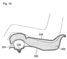
- Fig. 15 is a longitudinal cross-sectional view which shows a passenger protecting device along the longitudinal direction of a seat.
- An airbag 204 is disposed between a cushion frame (seat pan) 200 and a seat pad (seat cushion) 202 at the front portion of the seat.
- the airbag 204 extends in the width direction of the seat, and can be inflated by action of an inflator 206 (gas bag).
- the upper face of the seat pad 202 is covered with a trim cover 208, on which the passenger sits.
- the airbag 204 is inflated so as to push up the front portion of the seat pad 202, or so as to reduce the flexibility thereof due to the pressure of the airbag 204 underneath the seat pad 202, thereby preventing forward movement of the body of the passenger, as well as restraining the passenger.
- the passenger protecting device disclosed in the aforementioned Japanese Unexamined Patent Application Publication No. 10-217818 has the problem that the airbag 204 disposed underneath the seat pad 202 may be damaged due to friction between the airbag 204 and the seat pad 202.
- the airbag 204 tends to inflate with maximum inflation around the middle portion thereof in the longitudinal direction, in the shape of a spindle.
- the seat pad 202 With such inflation of the airbag 204 in the shape of a spindle, the seat pad 202 is pushed up by strong force around the middle portion in the longitudinal direction thereof, but is not pushed up by strong force around portions on both the left and right sides thereof where the left and right thighs of the passenger are to be positioned, as compared with the middle portion.
- an airbag with a great capacity as the airbag 204 sufficient for pushing up the left and right portions of the seat pad 202 by strong force.
- an inflator with a high performance as the inflator 206 corresponding to the airbag 204 with a great capacity.
- a passenger protecting device comprises: an inflatable bag disposed underneath the front portion of a seat cushion, for pushing up the lower face of the front portion of the seat cushion; a gas generator for inflating the bag in a case of emergency of a vehicle; and a cover for covering the bag, which opens or expands due to the pressure of the bag at the time of inflation of the bag, wherein the bag is held to the cover by a holding member.
- the bag held to said cover by a holding member may be disposed within a recess formed on the upper face of a seat pan disposed underneath the seat cushion, and the cover may be disposed so as to cover the recess.
- An opening may be provided in the seat pan below the seat cushion, and the bag held to said cover by a holding member may be disposed below the seat pan, and may be configured so as to pass through the opening and to press the seat cushion from below at the time of inflating.
- the cover may be disposed so as to block the opening at least partially.
- the bag held to said cover by a holding member may be disposed within a retainer having an open upper face, formed in the shape of a box without a lid, the cover being disposed so as to cover the retainer.
- the retainer may be fixed to at least the left and right frame portions of the seat.
- the cover may comprise a main plate portion disposed above the bag, and a surrounding frame portion hanging down from the main plate portion, with the bag disposed within the surrounding frame portion.
- the holding member may be disposed so as to traverse the surrounding frame portion.
- the holding member may further be attached to the surrounding frame portion by engaging with a retaining portion provided on the surrounding frame portion.
- a recessed portion into which the surrounding frame portion intrudes may be provided on the upper face of the seat pan below the seat cushion, and the edge of the main plate portion may extend to the perimeter of the recessed portion, so that the main plate portion covers the recessed portion from above.
- the edge portion of the main plate portion may be fastened to the perimeter portion of the recessed portion.
- a groove may be provided on the base of the recessed portion, into which the lower end of the surrounding frame portion intrudes.
- an opening may be provided in the seat pan below the seat cushion, with the main plate portion being disposed so as to block the opening at least partially, and the bag may be configured so as to press the main plate portion from below at the time of inflating to be released or extended, and also so as to press the seat cushion from below through the opening.
- a retainer is provided, the retainer may be disposed below the seat pan, and the bag and the surrounding frame portion may be supported by the retainer. Then, the retainer may be fixed to at least the left and right frame portions of the seat.
- a passenger protecting device comprises: an inflatable bag disposed underneath the front portion of a seat cushion, for pushing up the lower face of the front portion of the seat cushion; a gas generator for inflating the bag in a case of emergency of a vehicle; and a cover for covering the bag, which opens or expands due to the pressure of the bag at the time of inflation of the bag, wherein an opening is provided in the seat pan below the seat cushion, and the bag is disposed below the seat pan, and is configured so as to pass thorough the opening and to press the seat cushion from below at the time of inflating.
- the cover may be disposed so as to block the opening at least partially.
- the bag may be disposed within a retainer having an open upper face, formed in the shape of a box without a lid, the cover being disposed so as to cover the retainer. Then, the retainer may be fixed to at least the left and right frame portions of the seat.
- a passenger protecting device comprises: an inflatable bag disposed underneath the front portion of a seat cushion, for pushing up the lower face of the front portion of the seat cushion; a gas generator for inflating the bag in a case of emergency of a vehicle; and a cover for covering the bag, which opens or expands due to the pressure of the bag at the time of inflation of the bag, wherein the cover comprises a main plate portion disposed above the bag, and a surrounding frame portion hanging down from the main plate portion, with the bag disposed within the surrounding frame portion; and wherein a recessed portion into which the surrounding frame portion intrudes is provided on the upper face of the seat pan below the seat cushion; and wherein a groove is provided on the base of the recessed portion, into which the lower end of the surrounding frame portion intrudes.
- the bag may extend in the width direction of the seat cushion, and a bag envelope may be provided for surrounding said bag at least partway along the longitudinal direction.
- the bag envelope may surround only part of the bag in the longitudinal direction.
- the bag envelope may also surround from close to the left end to close to the right end of the bag.
- the circumference of the bag envelope may be smaller than the circumference of the bag in the inflated state.
- the bag envelope may be linked to the seat pan.
- the passenger protecting device has a configuration wherein the bag is covered with the cover, thereby preventing damage of the bag due to friction between the bag and the seat cushion or the like.
- the bag may be formed with reduced durability, thereby reducing costs of the bag having such a configuration.
- the cover opens or expands due to the pressure of the bag at the time of inflation of the bag. For example, the bag tears, separates from hooks, or deforms, due to inflation of the bag, whereby the inflating bag is released.
- the cover which expands at the time of inflation of the bag may be formed of an elastic material or a plastic material.
- the bag and cover can be integrally formed and mounted to the seat pan together.
- the passenger protecting device has a configuration wherein the bag is disposed within a recess formed on the upper face of the seat pan disposed underneath the cushion, and the cover is disposed so as to cover the recess, lumpiness due to the bag, the gas generator, and the like, disposed underneath the seat cushion, is reduced, thereby providing a comfortable seat.
- An arrangement may be made wherein an opening is provided in the seat pan below the seat cushion, and the bag is disposed below the seat pan, and is configured so as to pass thorough the opening and to press the seat cushion from below at the time of inflating.
- the cover is preferably disposed so as to block the opening at least partially.
- the seat cushion can be prevented from falling into the opening upon the passenger sitting in the seat, and comfort in sitting is maintained.
- the passenger protecting device may have a configuration wherein the bag and the gas generator are mounted within the retainer, and the cover is disposed so as to cover the retainer, and accordingly, the combination of the bag, the retainer, and the cover, is mounted as a single unit, thereby facilitating mounting operations for mounting the passenger protecting device.
- the retainer is preferably fixed to at least the left and right frame portions of the seat. Due to such a configuration, even in the event that passenger weight is applied to the inflated bag, the inflated bag can receive the passenger in a sure manner, since the bag is securely supported by the retainer.
- both the left and right end sides of the retainer may be directly fixed to the left and right frame portions by fastening devices such as bolts or the like or by welding or the like, or may be fixed through linking members such as brackets or the like.
- a retainer supporting member may be provided so as to bridge between the left and fight frame portions, with the retainer provided on this supporting member.
- This retainer may be fixed, not only to the left and right frame portions of the seat, but also to other portions (e.g., the seat pan, etc.) as well.
- the cover comprises a main plate portion disposed above the bag, and a surrounding frame portion hanging down from the main plate portion, with the bag disposed within the surrounding frame portion, the side perimeter of the bag is surrounded with the surrounding frame portion, and the upper side is covered with the main plate portion. Accordingly, damage due to abrasion or the like of the bag can be sufficiently prevented. Also, the bag can be prevented from directly striking against or hanging on the seat pan or the like can be prevented at the time of mounting the integrally assembled bag and cover to the seat pan.
- the bag In the case of a configuration wherein the holding member is disposed so as to traverse the surrounding frame portion, the bag is supported by the holding member from below, so the bag can be prevented in a sure manner from falling out of the cover at the time of mounting the integrally assembled bag and cover to the seat pan.
- the holding member In the case of a configuration wherein the holding member is attached to the surrounding frame portion by engaging with a retaining portion provided on the surrounding frame portion, the holding member can be easily mounted to the surrounding frame portion.
- providing a recessed portion on the upper face of the seat pan below the seat cushion into which surrounding frame portion intrudes prevents ill comfort in sitting due to the inflation-awaiting bag and gas generator and the like jutting into the seat cushion. Also, in this case, covering the recessed portion with the main plate portion prevents water (e.g., drinking water), trash, sand, and other like foreign material from entering, thereby preventing deterioration and damage of the airbag due to water, foreign material, and the like.
- water e.g., drinking water
- trash, sand, and other like foreign material from entering, thereby preventing deterioration and damage of the airbag due to water, foreign material, and the like.
- fastening the edge portion of the main plate portion to the perimeter portion of the recessed portion sufficiently prevents intrusion of water, foreign material, and the like, into the recessed portion.
- Providing a groove on the base of the recessed portion, into which the lower end of the surrounding frame portion intrudes forms an arrangement wherein, even in the event that water does flow in along the inner wall portion of the recessed portion, the water only collects in the groove, so the bag can be prevented from getting wet from the water.
- an arrangement may be made wherein an opening is provided in the seat pan below the seat cushion, and the bag module is disposed such that the main plate portion serving as a cover is placed within the opening.
- This configuration also prevents ill comfort in sitting due to the inflation-awaiting bag and gas generator and the like jutting into the seat cushion.
- the main plate portion prevents the seat cushion from falling into the opening upon the passenger sitting in the seat.
- the bag presses the main plate portion from below at the time of inflating, to be released or extended, and also so as to press the seat cushion from below through the opening.
- an arrangement may be made wherein the retainer is disposed below the seat pan, and the bag module is mounted on the retainer. Also, in this case, the retainer is preferably fixed to at least the left and right frame portions of the seat. Due to this configuration, the bag is securely supported by the retainer at the time of the inflated bag receiving the passenger.
- the retainer may be fixed, not only to the left and right frame portions of the seat, but also to other portions (e.g., the seat pan, etc.). Both the left and right end sides of the retainer may be directly fixed to the left and right frame portions, or may be fixed through linking members such as brackets or the like, or a retainer supporting member may be provided so as to bridge between the left and fight frame portions, with the retainer provided on this supporting member.
- Providing a tear portion in the main plate portion so as to tear open upon being pressed by the inflating bag allows the cover to tear open in the predetermined shape at the time of the bag inflating.
- the bag envelope may be included so as to cover at least a part of the bag along the longitudinal direction thereof, thereby preventing the middle portion of the bag along the longitudinal direction thereof from excessively expanding as compared with both ends thereof at the time of inflation of the bag, thereby sufficiently inflating both left and right ends of the bag.
- both left and right portions of the seat cushion are sufficiently pushed up from the bag disposed underneath the seat cushion.
- both left and right sides of the bag can be sufficiently inflated without using a high-performance gas generator, thereby reducing costs and weight of the gas generator.
- the bag envelope may be formed so as to surround a middle portion of the bag along the longitudinal direction thereof, or may be formed so as to surround multiple parts along the longitudinal direction thereof.
- the bag envelope can be formed of a small amount of material.
- the passenger protecting device may have a configuration wherein the bag envelope is formed so as to surround the bag over the entire range from a portion around the left end up to a portion around the right end.
- the bag can be inflated with generally the same magnitude (e.g., inflation width, or inflation cross-sectional area) over the range from a portion around the left end up to a portion around the right end.
- the lower face of the seat cushion is pushed up with generally the same pushing force over the range from the left portion up to the right portion.
- the bag envelope is preferably formed with a smaller surrounding length for surrounding the bag than with the inflated bag.
- the maximum surrounding length of the bag is suppressed to the surrounding length of the bag envelope at the time of inflation of the bag, thereby increasing the pressure of the bag. Furthermore, this action effects sufficiently rapid inflation of the bag over the entire range thereof.
- the passenger protecting device may have a configuration wherein the bag envelope is connected to the seat pan. With such a configuration, the inflated bag is restrained by the seat pan through the bag envelope. Thus, even in the event that pressing force is applied to the inflating bag in the forward direction from the waist of the passenger moving in the forward direction, forward movement of the bag is prevented or suppressed, thereby further reducing front movement of the body of the passenger.
- the passenger protecting device may have a configuration wherein the gas generator disposed within the bag is fixed to the seat pan with a fixing member passing through the bag, and the bag is supported between the gas generator and the seat pan.
- the bag is mounted onto the seat pan with an improved mounting strength. Furthermore, the tension applied to the fixing portion on the bag for fixing to the seat pan is reduced at the time of inflation of the bag.
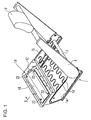
- Fig. 1 is a perspective view which shows a seat frame of a seat including a passenger protecting device
- Fig. 2 is a cross-sectional view taken along line II-II in Fig. 1.
- the frame forming the seat of an automobile comprises a base frame 1 and a back frame 4 rotatably mounted to the base frame 1 through a support shaft 2 and a reclining device (not shown). Furthermore, the back frame 4 includes a headrest 6 on the upper portion thereof.
- the base frame 1 includes a left and right side frames 1a and 1b, wherein a seat pan 8 is disposed between the front portions of the side frames 1a and 1b.
- a seat cushion (not shown) and a seat bag (not shown) formed of urethane or the like is mounted on the base frame 1 and the back frame 4.
- the seat pan 8 is disposed underneath the front portion of the seat cushion.
- reference numeral 1d in Fig. 1 denotes springs for supporting the seat cushion.
- a passenger protecting device 10 comprises an inflatable bag 12 for pushing up the lower face of the front portion of the seat cushion, a gas generator 14 for inflating the bag 12, a bag envelope 16 for surrounding the bag 12, a cover 18 for covering the bag 12, the gas generator 14, and the bag envelope 16, which are disposed on the upper face of the seat pan 8.
- the seat pan 8 includes a recess 20 on the upper face thereof, extending in the width direction of the seat (in the left and right direction thereof), and the bag 12 is folded and stored in the recess 20 along with the bag envelope 16 in normal situations (except for emergency situations such as a collision of the vehicle or the like). Note that the bag 12 is disposed within the recess 20 so as to extend along the width direction thereof.
- the bag envelope 16 is formed in the shape of a tube for surrounding the outer face of the bag 12.
- the bag envelope 16 is formed with a smaller surrounding length than with the bag 12 at the time of free inflation thereof.
- the bag envelope 16 may be formed with generally the same length in the width direction thereof (in the longitudinal direction of the bag 12) as with the bag 12, or may be formed with a smaller length thereof. Specifically, the bag envelope 16 is preferably formed with a length in the width direction of 40% to 100% of the length of the bag 12 in the width direction, more preferably with a length in the width direction of 50% to 90% thereof.
- the bag envelope 16 may be formed of a single envelope, or may be formed of multiple envelopes so as to surround multiple portions along the longitudinal direction.
- the bag envelope 16 formed of multiple envelopes is preferably formed with the sum of lengths of all the envelopes in the width direction within the aforementioned range.
- the bag envelope 16 is preferably formed of a material or with a configuration wherein the bag envelope 16 does not readily stretch, or does not stretch at all, in the circumferential direction thereof. Furthermore, the bag envelope 16 preferably has a moisture-proof (waterproof) configuration.
- the bag envelope 16 may be formed of a relatively flexible material such as cloth, a synthetic resin sheet, a synthetic resin mesh sheet, or the like, or may be formed of a rigid material such as a metal sheet, metal mesh, or the like.
- the passenger protecting device 10 has a configuration wherein the cylindrical gas generator 14 is disposed within the bag 12.
- the gas generator 14 is disposed such that the longitudinal direction thereof matches the width direction of the vehicle.
- the gas generator 14 includes gas nozzles (not shown) on the circumferential face thereof for discharging gas radially in all directions.
- the gas generator 14 includes a stud bolt 14a protruding therefrom. Specifically, the stud bolt 14a passes through the lower faces of the bag 12 and the bag envelope 16, and the bottom of the recess 20, and protrudes downward from the seat pan 8. The stud bolt 14a is secured to the seat pan 8 with a nut 14b. Thus, the gas generator 14, the bag 12, and the bag envelope 16, are secured to the seat pan 8.
- the passenger protecting device 10 has a configuration wherein multiple stud bolts 14a are provided to the gas generator 14 in the longitudinal direction thereof at predetermined intervals for securing the gas generator 14, the bag 12, and the bag envelope 16, to the seat pan 8.
- cover 18 is mounted for covering the bag 12, the bag envelope 16, and the gas generator 14, disposed within the recess 20.
- the cover 18 is formed in the shape of a plate with a size sufficient for covering the entire area of the recess 20, and is secured to the seat pan 8 through a pair of the flanges facing upward on the front and rear sides of the vehicle by bolts 22 and nuts 24.
- the cover 18 has a configuration wherein upon inflation of the bag 12, one of three actions is performed, i.e., 1) the cover 18 deforms so as to inflate upward following inflation of the bag 12, 2) the cover 18 tears due to the pressure from inflation of the bag 12 so as to allow further inflation of the bag 12, 3) the bolts 22 separate from the cover 18 due to inflation of the bag 12 so that the cover 18 is pushed up.
- the gas generator 14 upon detection of a frontal collision of the automobile, the gas generator 14 operates so as to discharge gas, and accordingly, the bag 12 inflates upward due to gas discharged from the gas generator 14 so as to push up or push away the cover 18.
- the front portion of the seat cushion is pushed up, or is pressed upward so as to reduce the flexibility thereof, thereby preventing or suppressing forward movement of the waist of the passenger.
- the bag envelope 16 is secured to the seat pan 8, and accordingly, the inflated bag 12 is restrained by the seat pan 8 through the bag envelope 16. This action prevents or suppresses the forward movement of the bag 12 at the time of the inflated bag 12 being affected by the forward pressing force from the waist of the passenger moving in the forward direction of the vehicle, thereby reducing forward movement of the body of the passenger.
- the bag envelope 16 encompasses the entire bag 12 including portions around both left and right ends thereof, and accordingly, the bag 12 inflates with generally the same inflation (the same inflation width or inflation cross-sectional area) over the entire range including portions around both left and right ends.
- the lower face of the seat cushion is pushed up with generally the same pressing force over the entire range including the left and right sides thereof.
- the bag envelope 16 is formed with a smaller surrounding length than the bag 12 at the time of free inflation thereof, and accordingly, with such a configuration wherein the bag 12 is inflated while being encompassed by the bag envelope 16, the maximum size (maximum diameter) thereof is suppressed to the size corresponding to the surrounding length of the bag envelope 16, thereby increasing the pressure of the bag 12.
- the bag 12 is rapidly inflated over the entire range.
- the passenger protecting device 10 has a configuration wherein the bag 12, the bag envelope 16, and the gas generator 14, are mounted within the recess 20 formed on the upper face of the seat pan 8, and are covered with the cover 18, thereby preventing damage thereof due to friction between these components and the seat cushion, or the like. Furthermore, the cover 18 does away with lumpiness of the seat cushion due to the bag 12, the bag envelope 16, the gas generator 14, the recess 20, and the like, thereby providing a comfortable seat cushion.
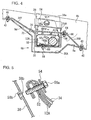
- Fig. 3 is a disassembled perspective view which shows another passenger protecting device
- Fig. 4 is a longitudinal cross-sectional view of the passenger protecting device
- Fig. 5 is a cross-sectional view taken along line V-V in Fig. 4.
- a passenger protecting device 10A includes a box-shaped retainer 30 without a lid disposed on the seat pan 8A, a bag 12A folded and disposed within the retainer 30, a gas generator 14A for inflating the bag 12A, a fixing member 32 for connecting and fixing the bag 12A and the gas generator 14A to the retainer 30 with stud bolts 58 described later, an envelope cloth 34 for wrapping the folded bag 12A so as to restrain the folded bag 12A, and a cover 18A mounted on the retainer 30 so as to cover an opening 30a on the upper face of the retainer 30.
- the seat pan 8A includes a bottom 8a disposed along the lower face of the seat cushion (not shown), and a pair of side walls 8b and 8b erected from the left and right perimeters of the bottom 8a.
- the side walls 8b include flange portions 8c on the upper ends thereof, protruding in the horizontal direction.
- the bottom 8a is formed in the form of a curve over the region from the middle portion to the rear portion thereof in the moving direction of the vehicle. That is to say, the bottom 8a includes a recess 20A on the upper face thereof for mounting the retainer 30. Note that the front perimeter of the recess 20A extends so as to form a slanted face 8d with a uphill inclination toward the forward direction.
- the retainer 30 is formed in the shape of a box without a lid having an opened upper face, and specifically, generally in the shape of a rectangular parallelepiped with a greater length in the width direction.
- the bag 12A is disposed within the retainer 30 so as to extend along the width direction.
- the front and rear perimeters along the opening 30a formed on the upper face of the retainer 30 protrudes so as to form a front supporting member 36F and a rear supporting member 36B for supporting the retainer 30 by being secured to the bottom 8a of the seat pan 8A.
- the left and right perimeters along the opening 30a thereof protrudes so as to form side-wall supporting members 38 and 38 for supporting the retainer 30 by being secured to the left and right side walls 8b and 8b of the seat pan 8A.
- the front supporting member 36F extends from the front edge along the opening 30a formed on the upper face of the retainer 30 forward with a predetermined uphill inclination along the slanted face 8b formed of the front perimeter of the recess 20A, and the tip thereof is fixed to the bottom 8a of the seat pan 8 around the peak of the slanted face 8d with bolts 40 and nuts 42.
- reference numeral 44 in Fig. 3 denotes a bolt inserting hole provided on the tip of the front supporting member 36F
- reference numeral 46 denotes a bolt inserting hole formed on the bottom 8a corresponding to the bolt inserting hole 44.
- the rear supporting member 36B extends backward from the rear edge of the opening 30a formed on the upper face of the retainer 30 with a downhill inclination, and the tip thereof is secured to the bottom 8a of the seat pan 8 on the rear edge of the recess 20A with the bolts 40 and the nuts 42.
- reference numeral 48 in Fig. 3 denotes a bolt inserting hole provided on the tip of the rear supporting member 36B
- reference numeral 50 denotes a bolt inserting hole formed on the bottom 8a corresponding to the bolt inserting hole 48.
- the side-wall supporting members 38 extend upward from the left and right edges of the opening 30a formed on the upper face of the retainer 30 along the side walls 8b of the seat pan 8A.
- the tips of the side-wall supporting members 38 protrude in the horizontal direction so as to form flange portions 38a which are disposed on the flange portions 8c formed on the upper ends of the side walls 8b and secured thereto with bolts (not shown).
- the envelope cloth 34 is formed in the shape of a tube with openings on both ends for mounting the bag 12A therewithin. Note that the envelope cloth 34 has a configuration wherein upon inflation of the bag 12A, the cloth 34 tears or expands following inflation of the bag 12A so as to allow further inflation of the bag 12A.
- the left and right ends of the bag 12A and the envelope cloth 34 are connected to the side-wall supporting members 38 of the retainer 30.
- the bag 12A includes connection members 52 on both left and right ends thereof for connecting the bag 12A to the side-wall supporting members 38.
- each connecting member 52 includes a bolt inserting hole (reference numeral is omitted).
- the envelope cloth 34 is formed with a greater length between both ends in the longitudinal direction than the distance between the connecting members 52 and 52 disposed on both ends of the bag 12A. As shown in Fig. 5, each of both ends of the envelope cloth 34 match the corresponding end of the bag 12A, and are folded back onto the reverse face (facing the side-wall supporting member 38) of the corresponding connecting member 52. As shown in the drawing, the envelope cloth 34 includes bolt inserting holes (reference numeral is omitted) at positions corresponding to the bolt inserting holes of the connecting members 52 such that each bolt inserting hole formed on the envelope cloth 34 matches the corresponding bolt inserting hole formed on the connecting member 52 at the time of folding back both ends of the envelope cloth 34 to the reverse faces of the connecting members 52.
- bolt inserting holes reference numeral is omitted
- a patching plate 54 is disposed on the front face of each connecting member 52 (which is opposite to the face onto which the end of the envelope cloth 34 is folded back) with the envelope cloth 34 introduced therebetween.
- Each patching plate 54 includes a bolt inserting hole 54a (Fig. 3) at a position corresponding to the bolt inserting hole formed on the connecting member 52.
- the patching plate 54 is formed in the shape of a "U" so as to surround the front face and both left and right sides of the side-wall supporting member 38.
- each side-wall supporting member 38 includes a bolt inserting hole 38b (Fig. 3) at a position corresponding to the bolt inserting hole of the connecting member 52.
- a bolt 56a is inserted into each combination formed of the bolt inserting holes of the patching plate 54, the envelope cloth 34, the connecting member 52, and the side-wall supporting member 38, and is screwed to a nut 56b (Fig. 5), whereby both ends of the bag 12A and the envelope cloth 34 are connected to the side-wall supporting members 38.
- a nut 56b Fig. 5
- Both ends of the envelope cloth 34 are folded down in two, and are supported and pressed between the patching plates 54 and the side-wall supporting members 38 by the aforementioned bolting. Thus, both ends of the envelope cloth 34 are sealed.
- the bag 12A includes the rod-shaped gas generator 14A therewithin, connected to the fixing member 32.
- the fixing member 32 is formed in the shape of a plate, is disposed so as to extend along the bottom of the retainer 30, and is disposed on the inner face of the lower portion of the bag 12A so as to press the lower portion of the bag 12A to the bottom of the retainer 30.
- a stud bolt 58 protrudes from the lower face of the fixing member 32. As shown in Fig. 4, the stud bolt 58 is inserted into bolt inserting holes (reference numerals are omitted) formed on the lower portions of the bag 12A and the envelope cloth 34, and on the bottom of the retainer 30, so as to protrude from the lower face of the retainer 30.
- a nut 60 is screwed to the stud bolt 58, whereby the lower portions of the bag 12A and the envelope cloth 34 are supported and pressed between the fixing member 32 and the bottom of the retainer 30, as well as fixing the fixing member 32 to the retainer 30.
- the gas generator 14A is disposed on the upper face of the fixing member 32 such that the longitudinal direction thereof matches the width direction, and is fixed to the fixing member 32 with a bracket 62.
- the bracket 62 is disposed so as to protrude from the rear edge of the fixing member 32, and is formed of a C-shaped band portion 62a formed in the shape of a "C" protruding from the upper faces of the fixing member 32, and a flange portion 62b extending from the tip of the C-shaped band portion 62a along the upper faces of the fixing member 32.
- the aforementioned stud bolt 58 is inserted so as to protrude downward from the flange portion 62b, and passes through the fixing member 32 so as to protrude downward from the fixing member 32.
- the gas generator 14A is inserted into a space surrounded by the C-shaped band portion 62a, following which the nut 60 is screwed to the stud bolt 58, whereby the flange portion 62b is pressed and fixed to the fixing member 32, thereby fixing the gas generator 14A to the fixing member 32.
- the cover 18A is formed generally in the shape of a rectangle with an area generally sufficient for covering the entire opening 30a formed on the upper face of the retainer 30.
- the cover 18A is disposed such that the front edge thereof matches the upper face of the front supporting member 36F, and the rear edge thereof matches the upper face of the rear supporting member 36B.
- the rear edge of the cover 18A is fixed to the rear supporting member 36B with bolts 64 and nuts 66.
- reference numeral 68 denotes a hole formed on the rear end of the cover 18A for inserting the bolt 64
- reference numeral 70 denotes a bolt inserting hole formed on the rear supporting member 36B corresponding to the bolt inserting hole 68.
- the cover 18A includes snap pins 72 on the lower face of the front edge thereof, protruding therefrom.
- the snap pins 72 are elastically engaged to the pin engaging openings 74 formed on the front supporting member 36F, whereby the front edge of the cover 18A is secured to the front supporting member 36F.
- the snap pins 72 Upon inflation of the bag 12A, the snap pins 72 is disengaged from the pin engaging openings 74, and the cover 18A is opened upward in the shape of a flap with the rear edge thereof as a fulcrum.
- the gas generator 14A upon detection of a frontal collision of the automobile, the gas generator 14A operates so as to discharge gas, thereby inflating the bag 12A due to gas discharged from the gas generator 14A.
- the envelope cloth 34 is pressed in the expanding direction by actions of the bag 12A, and tears or expands following inflation thereof so as to allow further inflation of the bag 12A.
- the inflating airbag 12A further inflates upward while pressing and opening the cover 18A so as to push up the front portion of the seat cushion, or so as to reduce the flexibility thereof due to pressure of the bag 12A disposed underneath the front portion of the seat cushion, thereby preventing or suppressing front movement of the waist of the passenger.
- the front supporting member 36F is disposed so as to extend forward from the front edge of the opening 30a formed on the upper face of the retainer 30 with a uphill inclination along the slanted face 8d formed on the front edge of the recess 20A of the seat pan 8A, extending forward with a uphill inclination.
- the bag 12A inflating forward comes into contact with the front supporting member 36F.
- the front supporting member 36F receives the bag 12A, thereby preventing forward movement of the bag 12A.
- the passenger protecting device 10A has a configuration wherein the bag 12A, the gas generator 14A, the fixing member 32, the envelope cloth 34, and the like, disposed within the retainer 30, are covered with the cover 18A, thereby preventing damage thereof due to friction between the seat cushion and these components. Furthermore, this configuration does away with lumpiness of on the seat cushion due to these components, thereby providing a comfortable seat cushion.
- the gas generator 14A is inserted into a space surrounded by the C-shaped band portion 62a of the fixing member 32, and the stud bolt 58 is inserted into the bolt inserting hole formed on the lower portion of the bag 12A so as to protrude outward therefrom, as well as disposing the fixing member 32 within the bag 12A.
- the bag 12A is folded into a long and slender form, following which the envelope cloth 34 is mounted onto the folded body formed of the bag 12A.
- the stud bolt 58 is inserted into the bolt inserting hole formed on the lower portion of the envelope cloth 34, as well, so as to protrude therefrom.
- the folded body formed of the bag 12A surrounded by the envelope cloth 34 is disposed within the retainer 30.
- the stud bolt 58 protruding from the lower portion of the envelope cloth 34 is inserted into the bolt inserting hole formed on the bottom of the retainer 30.
- the nut 60 is screwed to the stud bolt 58 from the lower side of the retainer 30, whereby the fixing member 32 is fixed to the retainer 30.
- both ends of the envelope cloth 34 are folded back onto the reverse face of the connecting members 52 disposed at both ends of the bag 12A, and the folded ends of the envelope cloth 34 and the connecting members 52 are secured to the corresponding side-wall supporting members 38 with the bolts 56a through the patching plates 54.
- the cover 18A is mounted onto the retainer 30.
- the retainer 30 is mounted onto the seat pan 8A.
- the mounting sequence for the passenger protecting device 10A, the bag 12A, the envelope cloth 34, the gas generator 14A, the fixing member 32, and the cover 18A are mounted onto the retainer 30 beforehand, thereby efficiently performing mounting operations for mounting the passenger protecting device 10A onto the seat pan 8A.
- Fig. 6(a) is a perspective view which shows another configuration for sealing both ends of the envelope cloth, wherein Fig. 6(b) is a cross-sectional view taken along line B-B in Fig. 6(a).
- Fig. 6 the same reference numerals denote the same components as in Fig. 3 through Fig. 5.
- An envelope cloth 34A shown in Fig. 6 is formed in the shape of a tube as with the envelope cloth 34 shown in Fig. 3 through Fig. 5 described above, and the bag 12A is inserted into either of the openings formed on both ends thereof so as to be stored therewithin.
- the envelope cloth 34A has a configuration wherein the openings of both ends thereof are closed such that the perimeter parts on each opening facing one another are in contact with each other, following which these perimeter parts are connected one to another with connecting means such as seaming, welding, or the like, thereby sealing the envelope cloth 34A.
- reference numeral 34a in Fig. 6(a) denotes holes for inserting bolts 56a, formed on both ends of the envelope cloth 34A so as to match the bolt inserting holes formed on the connecting members 52 disposed on the bag 12A.
- FIG. 7 the bag envelope 16 is mounted onto the bag 12A beforehand, following which the bag 12A with the bag envelope 16 is disposed within the envelope cloth 34A.
- reference numeral 52a in Fig. 7 denotes bolt inserting holes formed on the connecting members 52 disposed on both ends of the bag 12A.
- the envelope cloth may be formed of various kinds of materials such as cloth like the bag or the bag envelope, or with synthetic resin, metal, or the like, for example.
- Fig. 3 through Fig. 5, and Fig. 6 the mechanism is not restricted in particular.
- the envelope cloth includes tear lines (lines along which the envelope cloth is to tear) formed of perforations, grooves, or the like, and upon inflation of the bag, the envelope cloth tears along the tear lines so as to allow inflation of the bag.
- the envelope cloth includes an opening beforehand so as to allow inflation of the bag, and the opening is closed with a closing member in normal situations.
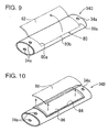
- Fig. 8 and Fig. 9 are perspective views which show envelope clothes 34B and 34C, respectively, including such tear lines
- Fig. 10 is a perspective view which shows an envelope cloth 34D including an opening for allowing inflation of the bag.
- the envelope cloth 34B shown in Fig. 8 includes an H-shaped tear line 76 formed of a pair of side tear lines 76a and 76a on both left and right ends on the upper face thereof, extending along the circumferential direction thereof, and a center tear line 76b, both ends of which are connected to the middle portions of the side tear lines 76a, extending around the middle portion of the upper face thereof in the longitudinal direction.
- reference numerals 78a and 78b denote two flaps formed due to tearing of the upper face of the envelope cloth 34B, which are shown by two-dot broken lines.
- the flaps 78a and 78b are opened upward following inflation of the bag.
- the envelope cloth 34C shown in Fig. 9 includes a C-shaped tear line 80 formed of a pair of side tear lines 80a and 80a on both left and right ends on the upper face thereof, extending along the circumferential direction thereof, and a longitudinal tear line 80b both ends of which are connected to the rear ends of the side tear lines 80a, extending along the rear end of the upper face thereof in the longitudinal direction.
- reference numeral 82 denotes a flap formed due to tearing of the upper face of the envelope cloth 34C, which is shown by two-dot broken lines. The flap 82 is opened upward following inflation of the bag.
- the envelope cloth 34D shown in Fig. 10 includes an opening 84 on the upper face thereof beforehand for allowing inflation of the bag at the time of inflation of the bag (not shown) therewithin.
- the opening 84 is closed with a closing sheet 86 in normal situations.
- the closing sheet 86 separates from the upper face of the envelope cloth 34D due to inflation pressure of the bag, thereby releasing the opening 84. This mechanism allows the bag to inflate upward through the opening 84.
- FIG. 11 is an explanatory diagram which shows an envelope cloth 34E having such a configuration, wherein (a) shows a sheet member at the time of wrapping, and (b) shows the sheet member with wrapping completed.
- the envelope cloth 34E is formed of a sheet member 88 formed of cloth, synthetic resin, metal, or the like, and is rolled, following which a pair of edges are engaged one to another with hooks 90, whereby wrapping thereof is completed.
- the hooks 90 are disengaged due to inflation pressure of the bag, whereby the pair of the edges of the sheet member 88 are disengaged so as to open both sides thereof.
- Fig. 12 is a disassembled perspective view which shows a passenger protecting device 10B having such a configuration. Note that, in Fig. 12, the same components are denoted by the same reference numerals as in Fig. 3 through Fig. 5.
- the passenger protecting device 10B has a configuration wherein the bag (not shown) does not include any connecting members on both ends thereof. Furthermore, an envelope cloth 34F for wrapping the folded body of the bag does not include any bolt inserting holes on both ends thereof. In such a configuration, the envelope cloth 34F is formed in the shape of a bag for wrapping the entire folded body of the bag.
- the retainer 30A for storing the bag and the envelope cloth 34F has generally the same configuration as with the retainer 30 without side-wall supporting members 38 and 38 disposed on both left and right sides thereof shown in Fig. 3 through Fig. 5.
- the passenger protecting device 10B has a configuration wherein the bag and the envelope cloth 34F are fixed within the retainer 30A by the stud bolt 58 protruding from the lower face of the fixing member (not shown) disposed within the bag.
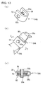
- Fig. 13(a) is a perspective view which shows a different patching plate 54A
- Fig. 13(b) is a perspective view which shows the patching plate 54A mounted on the side-wall supporting member
- Fig. 13(c) is a cross-sectional view taken along line C-C in Fig. 13(b).
- Fig. 14(a) is a perspective view which shows yet another patching plate 54B
- Fig. 14(a) is a perspective view which shows yet another patching plate 54B
- Fig. 14(a) is a perspective view which shows yet another patching plate 54B
- FIG. 14(b) is a cross-sectional view which shows the patching plate 54B mounted to the side-wall supporting member taken along line B-B in Fig. 14(a), which corresponds to Fig. 13(c).
- the patching plate 54A shown in Fig. 13 is formed generally in the shape of a "U" for surrounding the side-wall supporting member 38 over the front face thereof (the face for mounting the connecting member 52 disposed at the end of the bag), one of the sides thereof, and the rear face opposite to the front face.
- reference numeral 34G denotes an envelope cloth for wrapping the bag and the connecting members 52 disposed on both ends thereof.
- the patching plate 54A includes bolt inserting holes 92a and 94a at positions on a front-face portion 92 thereof for being mounted facing the front face of the side-wall supporting member 38, and a rear-face portion 94 for being mounted facing the rear face of the side-wall supporting member 38, corresponding to the hole (reference numeral is omitted in Fig. 13) formed on the side-wall supporting member 38 for inserting the bolt 56a.
- the nut 56b is disposed on the outer face of the rear-face portion 94 (which is opposite to the face facing the side-wall supporting member 38), wherein the bolt 56a which has passed through the bolt inserting hole 94a is screwed to the nut 56b. Note that the nut 56b is secured to the rear-face portion 94 by welding or the like.
- Both ends of the bag are connected to the side-wall supporting members 38 using the patching plates 54A as follows.
- each connecting member 52 disposed at the end of the bag is positioned on the front face of the side-wall supporting member 38, following which the patching plate 54A is mounted onto the side-wall portion 38 so as to surround the connecting member 52 and the side-wall supporting member 38 between the front-face portion 92 and the rear-face portion 94.
- the bolt 56a is inserted from the front face of the side-wall supporting member 38 into the bolt inserting holes formed on the front-face portion 92, the envelope cloth 34G, the connecting member 52, the side-wall supporting member 38, and the rear-face portion 94, following which the bolt 56a is screwed to the nut 56b.
- the connecting member 52 and the side-wall supporting member 38 are pressed between the front-face portion 92 and the rear-face portion 94, thereby fixing the connecting member 52 to the side-wall supporting member 38.
- the present passenger protecting device has the same configuration as shown in Fig. 3 through Fig. 5 described above, except for the above-described configuration for connecting both ends of the bag to the side-wall supporting members using the patching plates 54A, and the same components in Fig. 13 are denoted by the same reference numerals as in Fig. 3 through Fig. 5.
- the patching plate 54B shown in Fig. 14 is formed in the shape of a "U" in the same way as with the aforementioned patching plate 54A described above, is formed of a front-face portion 96 for being mounted facing the front face of the side-wall supporting member 38, and a rear-face portion 98 for being mounted facing the rear face of the side-wall supporting member 38, and is mounted onto the side-wall supporting member 38 so as to surround the connecting member 52 of the end of the bag and the side-wall supporting member 38 between the front-face portion 96 and the rear-face portion 98.
- the bag and the connecting members 52 disposed on both ends thereof are wrapped by the envelope cloth 34G, as well.
- the patching plate 54B includes a bolt inserting hole 96a at a position on only the front-face portion 96, corresponding to the hole (reference numeral thereof is omitted in Fig. 14) formed on the side-wall supporting member 38 for inserting the bolt 56a.
- the nut 56b is disposed on the rear face of the side-wall supporting member 38 (which is to be positioned between the side-wall supporting member 38 and the rear-face portion 98 of the patching plate 54), wherein the bolt 56a is screwed to the nut 56.
- the nut 56b is fixed to the side-wall supporting member 38 by welding or the like.
- the patching plate 54B includes protrusions 96b and 98b protruding from the inner faces of the front-face portion 96 and the rear-face portion 98, respectively (these inner faces are positioned facing one to another).
- the protrusions 96b and 98b protrude around the tips of the front-face portion 96 and the rear-face portion 98, respectively, facing one to another, as shown in Fig. 14(b).
- the protrusion 96b is formed with a height protruding from the inner face of the front-face portion 96 generally the same as the total thickness of the connecting member 52 and the envelope cloth 34G which wraps the connecting member 52.
- the protrusion 98b is formed with a greater height protruding from the inner face of the rear-face portion 98 than the height of the nut 56b protruding from the rear face of the side-wall supporting member 38.
- the gap between the protrusions 96b and 98b formed on the tips thereof is generally the same as the thickness of the side-wall supporting member 38, or is somewhat smaller than the thickness thereof.
- Both ends of the bag are connected to the side-wall supporting members 38 using the patching plates 56B as follows.
- each connecting member 52 disposed on the end of the bag is positioned on the front face of the side-wall supporting member 38, following which the patching plate 54B is mounted onto the side-wall supporting member 38 such that the connecting member 52 and the side-wall supporting member 38 are supported between the front-face portion 96 and the rear-face portion 98.
- the side-wall supporting member 38 is supported between the protrusions 96b and 98b protruding from the inner faces of the front-face portion 96 and the rear-face portion 98, respectively, whereby the patching plate 54B is temporarily fixed to the side-wall supporting member 38.
- the bolt 56a is inserted from the front face of the side-wall supporting member 38 into the bolt inserting holes formed on the front-face portion 96, the envelope cloth 34G, the connecting member 52, and the side-wall supporting member 38, following which the bolt 56a is screwed to the nut 56b disposed on the rear face of the side-wall supporting member 38.
- the connecting member 52 is supported and pressed between the front-face portion 96 and the side-wall supporting member 38, whereby the connecting member 52 is secured to the side-wall supporting member 38.
- the passenger protecting device has the same configuration as in Fig. 3 through Fig. 5 described above, except for the above-described configuration for connecting the both ends of the bag to the side-wall supporting portions using the patching plates 54B, and the same components shown in Fig. 14 are denoted by the same reference numerals as in Fig. 3 through Fig. 5.
- Fig. 16 illustrates a disassembled perspective view of the passenger protecting device 10C according to an embodiment of the present invention
- Fig. 17 is a disassembled view (longitudinal-section view) illustrating the configuration of attaching this passenger protecting device 10C to the seat pan
- Fig. 18 is a longitudinal-section view of a seat having this passenger protecting device 10C
- Fig. 19 is a plan view of a cover of the passenger protecting device 10C
- Fig. 20 is a longitudinal-section view of the passenger protecting device 10C with the bag inflated.
- the passenger protecting device 10C comprises a bag 12 long in the horizontal direction, which is folded up and placed on a seat pan 8, a gas generator 14A for inflating the bag 12, a fixing member 32 whereby the bag 12 and the gas generator 14A are each linked and fixed to the seat pan 8 by a stud bolt 58, an envelope cloth 34' for wrapping the folded article of the bag 12 so as to restrain the bag 12 in the folded state, a cover 100 for covering the folded article of the bag 12, and a holding member 110 for holding the folded article of the bag 12 to the cover 100.
- the cover 100 comprises a main plate portion 101 disposed above the folded article of the bag 12, a surrounding frame portion 102 hanging down from the lower face of the main plate portion 101, a tear line 103 for tearing open the main plate portion 101 at the time of the bag 12 inflating, and retaining claws 104 for the holding member 110 retaining against the surrounding frame portion 102.
- the main plate portion 101 is a generally rectangular plate shape.
- the surrounding frame portion 102 is a generally rectangular cylindrical shape longer in the sideways direction, with each of the faces extending along the four sides of the main plate portion 101.
- the edge portion 101a of the main plate portion 101 extends further outwards than the perimeter of the surrounding frame portion 102.
- Retaining claws 104 are erected on the outer face of each wall portion at the front side and rear side of the surrounding frame portion 102.
- the tear line 103 comprises a center tear portion which passes through the center portion of the main plate portion 101 and extends in the left and right directions, and a left tear portion and right tear portion which each connect to the left end and right end of the center tear portion.
- the tear line 103 is formed of a groove provided on the lower face of the main plate portion 101.
- the left tear portion and right tear portion each extend in the front and back directions (the front and back directions of the seat) along the base edges of the left and right wall portions of the surrounding frame portion 102.
- the ends of the center tear portion merge with around the center of the left tear portion and the right tear portion, respectively.
- the main plate portion 101 tears open along the center tear portion and left tear portion and right tear portion, forming two flaps 106 and 106 (Fig. 20) which open toward the front and the back, respectively.
- the cover 100 is formed of a synthetic resin such as polypropylene or the like, but is not restricted thereto.
- the holding member 110 is disposed so as to traverse the lower side of the surrounding frame portion 102 in the front-back direction.
- Retaining pieces 111 and 111 which pass around from the lower side of the surrounding frame portion 102 to the outer side faces of the front and rear wall portions of the surrounding frame portion 102, are provided on both ends of the holding member 110.
- Each retaining piece 111 has a retaining hole 112 to which a retaining claw 104 engages.
- This holding member 110 is formed of synthetic resin or metal for example, but is not restricted thereto.
- a recessed portion 20' where the surrounding frame portion 102 intrudes is formed on the upper face of the front portion of the seat pan 8.
- a rod-shaped gas generator 14A is linked to the fixing member 32 with the fixing member 32 being disposed within the bag 12, and with a stud bold 58 for fixing the fixing member 32 externally protruding from the bag through a bolt through hole (symbol omitted).
- a harness 14h for conducting electricity to the gas generator 14A is extended out from the bag 12 through a harness extending opening (omitted from the drawings) of the bag 12.
- the bag 12 is folded in a long and slender shape, and the folded article of the bag 12 is covered with the envelope cloth 34'.
- the stud bolt 58 also protrudes from a bolt through hole (symbol omitted) at the lower portion of the envelope cloth 34'.
- the folded article of the bag 12 covered by the envelope cloth 34' is positioned within the surrounding frame portion 102 of the cover 100.
- the holder member 110 is disposed so as to traverse the lower side of the surrounding frame portion 102, and the retaining pieces 111 on both ends thereof are retained by the retaining claws 104.
- the folded article of the bag 12 is supported from the below by the holding member 110, and is held within the surrounding frame portion 102.
- the stud bolt 58 protruding downwards from the folded article of the bag 12 is inserted into a bolt through hole 8f (Fig. 17) on the base of the recessed portion 20', and the surrounding frame portion 102 is made to intrude into the recessed portion 20'.
- the edge portion 101a of the main plate portion 101 extending outwards from the perimeter of the surrounding frame portion 102 overlaps with the perimeter of the recessed portion 20', so that the main plate portion 101 covers the recessed portion 20'.
- the stud bolt 58 is fastened with a nut 60 from the lower side of the seat pan 8, and the fixing member 32 is fixed to the base portion of the recessed portion 20'.
- the lower portions of the bag 12 and the enveloped cloth 34' are pinched and fixed between the fixing member 32 and the base of the recessed portion 20'.
- the perimeter portion 101a of the main plate portion 101 is fastened to the seat pan 8 by rivets 105 through rivet through holes 101b and 8e (Fig. 17).
- the passenger protecting device 10C is mounted to the seat pan 8.
- the folded article of the bag 12 can be held to the cover 100 by the holding member 110 and these attached to the seat pan 8 together, so assembly work of the passenger protecting device 10C to the seat pan 8 is easy.
- the bag 12 is held within the surrounding frame portion 102, so the bag 12 can be prevented from directly striking against or hanging on the seat pan 8 or the like at the time of mounting the integrally assembled bag 12 and cover 100 to the seat pan 8.
- the side perimeter of the bag 12 is surrounded by the surrounding frame portion 102, and the upper side is covered with the main plate portion 101, so damage due to abrasion or the like of the bag can be sufficiently prevented.
- the surrounding frame portion 102 is disposed within the recessed portion 20', preventing ill comfort in sitting due to the surrounding frame portion 102, and the bag 12 and gas generator 14A and the like therein jutting into the seat cushion.
- the recessed portion 20' is covered by the main plate portion 101, and further the edge portion 101a of the main plate portion 101 is fixed to the perimeter of the recessed portion 20' by rivets 105, preventing water (e.g., drinking water), trash, sand, and other like foreign material from entering the recessed portion 20', thereby preventing deterioration and damage of the bag 12 due to water, foreign material, and the like.
- water e.g., drinking water
- trash, sand, and other like foreign material may be used to fix the edge portion 101a to the seat pan 8.
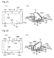
- Fig. 21 through Fig. 23 are each explanatory diagrams of covers 100A, 100B, and 100C, according to different embodiments each, wherein (a) is a plan view of the cover, and (b) is a cross-sectional diagram along line B-B in (a). Note that (b) illustrates the bag inflated (the state wherein the main plate portion of the cover has torn open).
- a tear line 103A is provided on the lower face of the main plate portion 101, comprising a horizontal tear portion which extends in the horizontal direction along the base edge of the wall portion at the front side of the surrounding frame portion 102, and a left tear portion and right tear portion which each extend in the front-back direction along the base edges of the wall portions at the left and right sides of the surrounding frame portion 102, and connect to the left end and right end of the horizontal tear portion.
- the main plate portion 101 tears open following the horizontal tear portion at the front side and the left tear portion and right tear portion, so that the general entirety of the main plate portion 101 opens toward the back as a single flap 106A.
- a tear line 103B is provided on the lower face of the main plate portion 101, comprising a horizontal tear portion which extends in the horizontal direction along the base edge of the wall portion at the back side of the surrounding frame portion 102, and a left tear portion and right tear portion which each extend in the front-back direction along the base edges of the wall portions at the left and right sides of the surrounding frame portion 102, and connect to the left end and right end of the horizontal tear portion.
- the main plate portion 101 tears open following the horizontal tear portion at the back side and the left tear portion and right tear portion, so that the general entirety of the main plate portion 101 opens toward the front as a single flap 106B.
- a tear line 103C is provided on the lower face of the main plate portion 101, comprising two horizontal tear portions which extend in the horizontal direction along the base edges of the wall portions at the front and back sides of the surrounding frame portion 102, and a vertical tear portion which extends in the front-back direction so as to connect the horizontal tear portions at the middle portions thereof.
- the main plate portion 101 tears open following the horizontal tear portions at the front and back sides and the vertical tear portion, so that the main plate portion 101 opens toward the left and right as two flaps 106C and 106C.
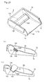
- Fig. 24 is a cross-sectional view of a cover 100D according to yet another embodiments, wherein (a) illustrates a state wherein the bag is not inflated, and (b) illustrates a state wherein the bag is inflated (state wherein the main plate portion of the cover is torn open).
- the main plate portion 101D is curved in a convex shape upwards so that around the center portion in the front and back direction is the highest position.
- a tear line 103 extending in the left and right directions is provided around the middle in the front and back direction.
- the main plate portion 101 tears open following the tear line 103, so that the plate portion 101 opens toward the front and back as flaps 106D and 106D.
- the flaps 106D and 106D are each curved so as to contour along the outer face of the bag 12, so a situation wherein the flaps 106D jut into the seat cushion and excessively press the seat cushion can be prevented.
- Fig. 25 illustrates a longitudinal-section view of a passenger protecting device 10E according to yet another embodiment.
- the passenger protecting device 10E also comprises a bag 12 long in the horizontal direction, which is folded up and placed on the seat pan, a gas generator 14A for inflating the bag 12, a fixing member 32 whereby the bag 12 and the gas generator 14A are each linked and fixed to the seat pan 8 by a stud bolt 58, and a cover 100E for covering the folded article of the bag 12.
- the cover 100E comprises a main plate portion 101 disposed above the folded article of the bag 12, a surrounding frame portion 102 hanging down from the lower face of the main plate portion 101, and a tear line 103 for tearing open the main plate portion 101 at the time of the bag 12 inflating.
- a recessed portion 120 is provided on the upper face of the seat pan 8 for placing the passenger protecting device, and the surrounding frame portion 102 is disposed within the recessed portion 120. Also, the edge portion 101a of the main plate portion 101 extends to the perimeter portion of this recessed portion 120, and overlaps the upper face of the seat pan 8, and is fastened by rivets 105.
- a groove 121 is formed on the perimeter portion of the base of the recessed portion 120, with the lower end of the surrounding frame portion 102 intruding into this groove 121 over the entire circumference thereof.
- the groove 121 is provided on the perimeter portion of the base of the recessed portion 120 where the surrounding frame portion 102 of the cover 100E intrudes, and the bottom end of the surrounding frame portion 102 is within the groove 121, so even in the event that water does flow in along the inner wall portion of the recessed portion 120, the water only collects in the groove 121, so the bag 12 can be prevented from getting wet from the water.
- a passenger protecting device 10E' shown in Fig. 26 providing a groove 121A on the perimeter portion of the base of the recessed portion 120A where the surrounding frame portion 102 of the cover 100E' intrudes so as to be capable of tightly engaging with the bottom end of the surrounding frame portion 102, can sufficiently prevent water from flowing into the recessed portion 121A.
- Fig. 27(a) is a perspective view of a passenger protecting device according to another embodiment
- Fig. 27(b) is a cross-sectional view along line B-B in Fig. 27(a)
- Fig. 27(c) is a cross-sectional view along the same portion as in Fig. 27(b) in the state wherein the bag has inflated.
- the base frame 1A of the seat has a seat pan 8A which continuously extends in the front-back direction, from between the front portions of the left and right side frames 1a and 1b, to the back portions thereof. That is to say, with the present embodiment, the seat cushion (omitted from the drawings) is supported by a single seat pan 8A from the front end to the rear end. A passenger protecting device 10F is disposed below the rear portion of this seat pan 8A. With this embodiment, an opening 130 permitting the inflated bag 12 to pass through to the seat cushion side is provided at the front portion of the seat pan 8A.
- the passenger protecting device 10F comprises a container-shaped retainer 140 which is opened at the upper face side, an inflatable bag 12 folded and stored within the retainer 140, an inflator (omitted from the drawings) for inflating the bag 12, and a cover 100F which closes off the upper face of the retainer 140.
- the bag 12 may be formed into a module beforehand by being held by a holding member (omitted from the drawings) to the cover 100F.
- the retainer 140 extends in the left and right directions so as to traverse the opening 130 in this embodiment, and both ends thereof are linked to the left and right side frames 1a and 1b by fixing devices such as bolts and nuts or the like (omitted from the drawings).
- the bag 12 extends in the left and right directions within this retainer 140.
- the inflator is disposed within the bag 12, and is fixed to the base of the retainer 140 through the lower portion of the bag 12.
- the cover 100F is configured so as to tear open upon being pressed by the bag 12 at the time of the bag 12 inflating.
- the bag 12 upon the bag 12 inflating, the bag 12 passes through the opening 130 while pressing the cover 100F open and expands out above the seat pan 8A, and presses the front portion of the seat cushion upwards.
- the passenger protecting device 10F is disposed below the seat pan 8A, so the passenger protecting device 10F does not cause ill ease of comfort in sitting on the seat. Also, with this embodiment, the retainer 140 of the passenger protecting device 10F is disposed traversing the opening 130 of the seat pan 8A, and the cover 100F mounted to the retainer 140 closes off the opening 130 at least partially, thereby preventing the seat cushion from falling into the opening 130 upon the passenger sitting thereupon.
- the retainer 140 is fixed to the left and right side frames 1a and 1b, so even in the event that a great weight is placed on the inflated bag from the passenger, the bag 12 is securely supported by the retainer 140, so the passenger can be received by the inflated bag 12 in a sure manner.
- the left and right side ends of the retainer 140 are directly fixed to the left and right side frames 1a and 1b by fixing devices such as bolts or the like, but may be fixed by linking members such as brackets or the like (omitted from the drawings). Also, a retainer supporting member (omitted from the drawings) may be provided so as to bridge between the side frames 1a and 1b, with the retainer 140 mounted to this supporting member.
- the retainer 140 may be fixed to other members (e.g., the seat pan 8A, etc.), besides the left and right side frames 1a and 1b.
Landscapes
- Engineering & Computer Science (AREA)
- Mechanical Engineering (AREA)
- Aviation & Aerospace Engineering (AREA)
- Transportation (AREA)
- Air Bags (AREA)
- Seats For Vehicles (AREA)
Abstract
Description
- The present invention relates to a passenger protecting device for protecting a passenger in a seat in a vehicle such as an automobile in the event of a collision, and particularly relates to a passenger protecting device having a configuration for restraining the waist of the passenger in a frontal collision so as to prevent forward and backward movement of the body of the passenger.
- As a system for protecting the passenger in an automobile in a collision, more specifically, as a passenger protecting device for preventing the submarine phenomenon, which is a phenomenon wherein the passenger who wears a seat belt passes under a lap belt in a frontal collision, a passenger protecting device is disclosed in Japanese Unexamined Patent Application Publication No. 10-217818, wherein an inflatable bag is disposed between a seat cushion and a seat pan, and is inflated so as to push up the front portion of the seat cushion in a collision of the vehicle.
- Fig. 15 is a longitudinal cross-sectional view which shows a passenger protecting device along the longitudinal direction of a seat. An
airbag 204 is disposed between a cushion frame (seat pan) 200 and a seat pad (seat cushion) 202 at the front portion of the seat. Theairbag 204 extends in the width direction of the seat, and can be inflated by action of an inflator 206 (gas bag). The upper face of theseat pad 202 is covered with atrim cover 208, on which the passenger sits. - In the event that the
inflator 206 operates in a collision of the vehicle, theairbag 204 is inflated so as to push up the front portion of theseat pad 202, or so as to reduce the flexibility thereof due to the pressure of theairbag 204 underneath theseat pad 202, thereby preventing forward movement of the body of the passenger, as well as restraining the passenger. - The passenger protecting device disclosed in the aforementioned Japanese Unexamined Patent Application Publication No. 10-217818 has the problem that the
airbag 204 disposed underneath theseat pad 202 may be damaged due to friction between theairbag 204 and theseat pad 202. - Furthermore, with the passenger protecting device disclosed in the aforementioned Japanese Unexamined Patent Application Publication No. 10-217818, the
airbag 204 tends to inflate with maximum inflation around the middle portion thereof in the longitudinal direction, in the shape of a spindle. With such inflation of theairbag 204 in the shape of a spindle, theseat pad 202 is pushed up by strong force around the middle portion in the longitudinal direction thereof, but is not pushed up by strong force around portions on both the left and right sides thereof where the left and right thighs of the passenger are to be positioned, as compared with the middle portion. Accordingly, there is the need to employ an airbag with a great capacity as theairbag 204, sufficient for pushing up the left and right portions of theseat pad 202 by strong force. In addition, there is the need to employ an inflator with a high performance as theinflator 206, corresponding to theairbag 204 with a great capacity. - It is an object of the present invention to provide a passenger protecting device for preventing an airbag disposed underneath a cushion from being damaged due to friction between the airbag and the cushion, or the like.
- Furthermore, it is an object of the present invention to provide a passenger protecting device wherein the entire airbag including the left and right portions thereof is rapidly inflated so as to sufficiently push up the lower face of the entire seat cushion including the left and right portions thereof, without a gas generator with a high performance.
- According to the present invention, these objects are achieved by a passenger protection device according to
claims - According to an aspect of the present invention, a passenger protecting device comprises: an inflatable bag disposed underneath the front portion of a seat cushion, for pushing up the lower face of the front portion of the seat cushion; a gas generator for inflating the bag in a case of emergency of a vehicle; and a cover for covering the bag, which opens or expands due to the pressure of the bag at the time of inflation of the bag, wherein the bag is held to the cover by a holding member.
The bag held to said cover by a holding member may be disposed within a recess formed on the upper face of a seat pan disposed underneath the seat cushion, and the cover may be disposed so as to cover the recess. - An opening may be provided in the seat pan below the seat cushion, and the bag held to said cover by a holding member may be disposed below the seat pan, and may be configured so as to pass through the opening and to press the seat cushion from below at the time of inflating. The cover may be disposed so as to block the opening at least partially.
- The bag held to said cover by a holding member may be disposed within a retainer having an open upper face, formed in the shape of a box without a lid, the cover being disposed so as to cover the retainer. The retainer may be fixed to at least the left and right frame portions of the seat.
- The cover may comprise a main plate portion disposed above the bag, and a surrounding frame portion hanging down from the main plate portion, with the bag disposed within the surrounding frame portion. The holding member may be disposed so as to traverse the surrounding frame portion. The holding member may further be attached to the surrounding frame portion by engaging with a retaining portion provided on the surrounding frame portion.
- A recessed portion into which the surrounding frame portion intrudes may be provided on the upper face of the seat pan below the seat cushion, and the edge of the main plate portion may extend to the perimeter of the recessed portion, so that the main plate portion covers the recessed portion from above. The edge portion of the main plate portion may be fastened to the perimeter portion of the recessed portion. Further, a groove may be provided on the base of the recessed portion, into which the lower end of the surrounding frame portion intrudes.
- If the cover includes a main plate portion, an opening may be provided in the seat pan below the seat cushion, with the main plate portion being disposed so as to block the opening at least partially, and the bag may be configured so as to press the main plate portion from below at the time of inflating to be released or extended, and also so as to press the seat cushion from below through the opening. If, in addition, a retainer is provided, the retainer may be disposed below the seat pan, and the bag and the surrounding frame portion may be supported by the retainer. Then, the retainer may be fixed to at least the left and right frame portions of the seat.
- If a main plate portion is provided, a tear portion may be formed in the main plate portion so as to tear open upon being pressed by the inflating bag.
According to a second aspect of the invention, a passenger protecting device comprises: an inflatable bag disposed underneath the front portion of a seat cushion, for pushing up the lower face of the front portion of the seat cushion; a gas generator for inflating the bag in a case of emergency of a vehicle; and a cover for covering the bag, which opens or expands due to the pressure of the bag at the time of inflation of the bag, wherein an opening is provided in the seat pan below the seat cushion, and the bag is disposed below the seat pan, and is configured so as to pass thorough the opening and to press the seat cushion from below at the time of inflating. - According to the second aspect of the invention, the cover may be disposed so as to block the opening at least partially. Furthermore, the bag may be disposed within a retainer having an open upper face, formed in the shape of a box without a lid, the cover being disposed so as to cover the retainer. Then, the retainer may be fixed to at least the left and right frame portions of the seat.
According to a third aspect of the invention, a passenger protecting device comprises: an inflatable bag disposed underneath the front portion of a seat cushion, for pushing up the lower face of the front portion of the seat cushion; a gas generator for inflating the bag in a case of emergency of a vehicle; and a cover for covering the bag, which opens or expands due to the pressure of the bag at the time of inflation of the bag, wherein the cover comprises a main plate portion disposed above the bag, and a surrounding frame portion hanging down from the main plate portion, with the bag disposed within the surrounding frame portion; and wherein a recessed portion into which the surrounding frame portion intrudes is provided on the upper face of the seat pan below the seat cushion; and wherein a groove is provided on the base of the recessed portion, into which the lower end of the surrounding frame portion intrudes. - In a passenger protecting device, according to any one aspect of the invention, the bag may extend in the width direction of the seat cushion, and a bag envelope may be provided for surrounding said bag at least partway along the longitudinal direction. The bag envelope may surround only part of the bag in the longitudinal direction. The bag envelope may also surround from close to the left end to close to the right end of the bag. Further, the circumference of the bag envelope may be smaller than the circumference of the bag in the inflated state. Still further, the bag envelope may be linked to the seat pan.
- The passenger protecting device according to an aspect of the present invention has a configuration wherein the bag is covered with the cover, thereby preventing damage of the bag due to friction between the bag and the seat cushion or the like. Thus, the bag may be formed with reduced durability, thereby reducing costs of the bag having such a configuration. Note that the cover opens or expands due to the pressure of the bag at the time of inflation of the bag. For example, the bag tears, separates from hooks, or deforms, due to inflation of the bag, whereby the inflating bag is released. The cover which expands at the time of inflation of the bag may be formed of an elastic material or a plastic material. Furthermore, because the bag is held to the cover by a holding member, the bag and cover can be integrally formed and mounted to the seat pan together.
- If the passenger protecting device according to the present invention has a configuration wherein the bag is disposed within a recess formed on the upper face of the seat pan disposed underneath the cushion, and the cover is disposed so as to cover the recess, lumpiness due to the bag, the gas generator, and the like, disposed underneath the seat cushion, is reduced, thereby providing a comfortable seat.
- An arrangement may be made wherein an opening is provided in the seat pan below the seat cushion, and the bag is disposed below the seat pan, and is configured so as to pass thorough the opening and to press the seat cushion from below at the time of inflating. With this configuration as well, ill comfort in sitting due to the inflation-awaiting bag and gas generator and the like jutting into the seat cushion can be prevented.
- In this case, the cover is preferably disposed so as to block the opening at least partially. Thus, the seat cushion can be prevented from falling into the opening upon the passenger sitting in the seat, and comfort in sitting is maintained.
- Furthermore, the passenger protecting device according to the present invention may have a configuration wherein the bag and the gas generator are mounted within the retainer, and the cover is disposed so as to cover the retainer, and accordingly, the combination of the bag, the retainer, and the cover, is mounted as a single unit, thereby facilitating mounting operations for mounting the passenger protecting device.
- In this case, the retainer is preferably fixed to at least the left and right frame portions of the seat. Due to such a configuration, even in the event that passenger weight is applied to the inflated bag, the inflated bag can receive the passenger in a sure manner, since the bag is securely supported by the retainer.
- Also, note that both the left and right end sides of the retainer may be directly fixed to the left and right frame portions by fastening devices such as bolts or the like or by welding or the like, or may be fixed through linking members such as brackets or the like. Also, a retainer supporting member may be provided so as to bridge between the left and fight frame portions, with the retainer provided on this supporting member.
- This retainer may be fixed, not only to the left and right frame portions of the seat, but also to other portions (e.g., the seat pan, etc.) as well.
- In the case of a configuration wherein the cover comprises a main plate portion disposed above the bag, and a surrounding frame portion hanging down from the main plate portion, with the bag disposed within the surrounding frame portion, the side perimeter of the bag is surrounded with the surrounding frame portion, and the upper side is covered with the main plate portion. Accordingly, damage due to abrasion or the like of the bag can be sufficiently prevented. Also, the bag can be prevented from directly striking against or hanging on the seat pan or the like can be prevented at the time of mounting the integrally assembled bag and cover to the seat pan.
- In the case of a configuration wherein the holding member is disposed so as to traverse the surrounding frame portion, the bag is supported by the holding member from below, so the bag can be prevented in a sure manner from falling out of the cover at the time of mounting the integrally assembled bag and cover to the seat pan.
- In the case of a configuration wherein the holding member is attached to the surrounding frame portion by engaging with a retaining portion provided on the surrounding frame portion, the holding member can be easily mounted to the surrounding frame portion.
- According to an aspect of the present invention, providing a recessed portion on the upper face of the seat pan below the seat cushion into which surrounding frame portion intrudes prevents ill comfort in sitting due to the inflation-awaiting bag and gas generator and the like jutting into the seat cushion. Also, in this case, covering the recessed portion with the main plate portion prevents water (e.g., drinking water), trash, sand, and other like foreign material from entering, thereby preventing deterioration and damage of the airbag due to water, foreign material, and the like.
- In this case, fastening the edge portion of the main plate portion to the perimeter portion of the recessed portion sufficiently prevents intrusion of water, foreign material, and the like, into the recessed portion.
- Providing a groove on the base of the recessed portion, into which the lower end of the surrounding frame portion intrudes forms an arrangement wherein, even in the event that water does flow in along the inner wall portion of the recessed portion, the water only collects in the groove, so the bag can be prevented from getting wet from the water.
- Also, an arrangement may be made wherein an opening is provided in the seat pan below the seat cushion, and the bag module is disposed such that the main plate portion serving as a cover is placed within the opening. This configuration also prevents ill comfort in sitting due to the inflation-awaiting bag and gas generator and the like jutting into the seat cushion. Also, the main plate portion prevents the seat cushion from falling into the opening upon the passenger sitting in the seat. The bag presses the main plate portion from below at the time of inflating, to be released or extended, and also so as to press the seat cushion from below through the opening.
- In this case, an arrangement may be made wherein the retainer is disposed below the seat pan, and the bag module is mounted on the retainer. Also, in this case, the retainer is preferably fixed to at least the left and right frame portions of the seat. Due to this configuration, the bag is securely supported by the retainer at the time of the inflated bag receiving the passenger.
- Again, the retainer may be fixed, not only to the left and right frame portions of the seat, but also to other portions (e.g., the seat pan, etc.). Both the left and right end sides of the retainer may be directly fixed to the left and right frame portions, or may be fixed through linking members such as brackets or the like, or a retainer supporting member may be provided so as to bridge between the left and fight frame portions, with the retainer provided on this supporting member.
- Providing a tear portion in the main plate portion so as to tear open upon being pressed by the inflating bag allows the cover to tear open in the predetermined shape at the time of the bag inflating.
- Furthermore, with the passenger protecting device according to an aspect of the present invention, the bag envelope may be included so as to cover at least a part of the bag along the longitudinal direction thereof, thereby preventing the middle portion of the bag along the longitudinal direction thereof from excessively expanding as compared with both ends thereof at the time of inflation of the bag, thereby sufficiently inflating both left and right ends of the bag. As a result, both left and right portions of the seat cushion are sufficiently pushed up from the bag disposed underneath the seat cushion. Furthermore, both left and right sides of the bag can be sufficiently inflated without using a high-performance gas generator, thereby reducing costs and weight of the gas generator.
- Furthermore, the bag envelope may be formed so as to surround a middle portion of the bag along the longitudinal direction thereof, or may be formed so as to surround multiple parts along the longitudinal direction thereof. With such a configuration wherein the bag envelope is formed so as to cover a part of the bag along the longitudinal direction thereof, the bag envelope can be formed of a small amount of material.
- The passenger protecting device according to an aspect of the present invention may have a configuration wherein the bag envelope is formed so as to surround the bag over the entire range from a portion around the left end up to a portion around the right end. With such a configuration, the bag can be inflated with generally the same magnitude (e.g., inflation width, or inflation cross-sectional area) over the range from a portion around the left end up to a portion around the right end. Thus, the lower face of the seat cushion is pushed up with generally the same pushing force over the range from the left portion up to the right portion.
- With the passenger protecting device according to an aspect of the present invention, the bag envelope is preferably formed with a smaller surrounding length for surrounding the bag than with the inflated bag. With such a configuration, the maximum surrounding length of the bag is suppressed to the surrounding length of the bag envelope at the time of inflation of the bag, thereby increasing the pressure of the bag. Furthermore, this action effects sufficiently rapid inflation of the bag over the entire range thereof.
- The passenger protecting device may have a configuration wherein the bag envelope is connected to the seat pan. With such a configuration, the inflated bag is restrained by the seat pan through the bag envelope. Thus, even in the event that pressing force is applied to the inflating bag in the forward direction from the waist of the passenger moving in the forward direction, forward movement of the bag is prevented or suppressed, thereby further reducing front movement of the body of the passenger.
- The passenger protecting device may have a configuration wherein the gas generator disposed within the bag is fixed to the seat pan with a fixing member passing through the bag, and the bag is supported between the gas generator and the seat pan. With such a configuration, the bag is mounted onto the seat pan with an improved mounting strength. Furthermore, the tension applied to the fixing portion on the bag for fixing to the seat pan is reduced at the time of inflation of the bag.
- Further advantages of the present invention will be more easily understood from the following description of preferred embodiments with reference to the accompanying drawings.
- Fig. 1 is a perspective view which shows a seat frame including a passenger protecting device.
- Fig. 2 is a cross-sectional view taken along line II-II in Fig. 1.
- Fig. 3 is a disassembled perspective view which shows another passenger protecting device.
- Fig. 4 is a longitudinal cross-sectional view which shows the passenger protecting device shown in Fig. 3.
- Fig. 5 is a cross-sectional view taken along line V-V in Fig. 4.
- Fig. 6 is an explanatory diagram which shows another configuration for sealing both ends of an envelope cloth.
- Fig. 7 is a disassembled perspective view which shows a combination of a bag with a bag envelope and an envelope cloth.
- Fig. 8 is a perspective view which shows an arrangement example of an envelope cloth including tear lines.
- Fig. 9 is a perspective view which shows another arrangement example of an envelope cloth including tear lines.
- Fig. 10 is a perspective view which shows an arrangement example of an envelope cloth including an opening for releasing the inflated bag.
- Fig. 11 is an explanatory diagram for describing another arrangement example of an envelope cloth.
- Fig. 12 is a disassembled perspective view which shows a passenger protecting device.
- Fig. 13 is an explanatory diagram which shows another configuration example of a patching plate.
- Fig. 14 is an explanatory diagram which shows another configuration example of a patching plate.
- Fig. 15 is a cross-sectional view which shows a conventional passenger protecting device.
- Fig. 16 is a disassembled perspective view of a passenger protecting device according to an embodiment of the present invention.
- Fig. 17 is a disassembled view illustrating the configuration of attaching the passenger protecting device shown in Fig. 16 to the seat pan.
- Fig. 18 is a longitudinal-sectional view of a seat having the passenger protecting device shown in Fig. 16.
- Fig. 19 is a plan view of a cover of the passenger protecting device shown in Fig. 16.
- Fig. 20 is a longitudinal-sectional view of the passenger protecting device shown in Fig. 16 with the bag inflated.
- Fig. 21 is an explanatory diagram of another configuration example of the cover.
- Fig. 22 is an explanatory diagram of another configuration example of the cover.
- Fig. 23 is an explanatory diagram of another configuration example of the cover.
- Fig. 24 is an explanatory diagram of another configuration example of the cover.
- Fig. 25 is a longitudinal-sectional view of a passenger protecting device according to another embodiment of the present invention.
- Fig. 26 is a longitudinal-sectional view of a passenger protecting device according to another embodiment of the present invention.
- Fig. 27 is a configuration diagram of a passenger protecting device according to another embodiment of the present invention.
- Fig. 1 is a perspective view which shows a seat frame of a seat including a passenger protecting device, and Fig. 2 is a cross-sectional view taken along line II-II in Fig. 1.
- The frame forming the seat of an automobile comprises a
base frame 1 and a back frame 4 rotatably mounted to thebase frame 1 through a support shaft 2 and a reclining device (not shown). Furthermore, the back frame 4 includes a headrest 6 on the upper portion thereof. Thebase frame 1 includes a left and right side frames 1a and 1b, wherein aseat pan 8 is disposed between the front portions of the side frames 1a and 1b. - Furthermore, a seat cushion (not shown) and a seat bag (not shown) formed of urethane or the like is mounted on the
base frame 1 and the back frame 4. Theseat pan 8 is disposed underneath the front portion of the seat cushion. Note thatreference numeral 1d in Fig. 1 denotes springs for supporting the seat cushion. - A
passenger protecting device 10 comprises aninflatable bag 12 for pushing up the lower face of the front portion of the seat cushion, agas generator 14 for inflating thebag 12, abag envelope 16 for surrounding thebag 12, acover 18 for covering thebag 12, thegas generator 14, and thebag envelope 16, which are disposed on the upper face of theseat pan 8. - With such a configuration, the
seat pan 8 includes arecess 20 on the upper face thereof, extending in the width direction of the seat (in the left and right direction thereof), and thebag 12 is folded and stored in therecess 20 along with thebag envelope 16 in normal situations (except for emergency situations such as a collision of the vehicle or the like). Note that thebag 12 is disposed within therecess 20 so as to extend along the width direction thereof. - The
bag envelope 16 is formed in the shape of a tube for surrounding the outer face of thebag 12. Thebag envelope 16 is formed with a smaller surrounding length than with thebag 12 at the time of free inflation thereof. - Note that the
bag envelope 16 may be formed with generally the same length in the width direction thereof (in the longitudinal direction of the bag 12) as with thebag 12, or may be formed with a smaller length thereof. Specifically, thebag envelope 16 is preferably formed with a length in the width direction of 40% to 100% of the length of thebag 12 in the width direction, more preferably with a length in the width direction of 50% to 90% thereof. Thebag envelope 16 may be formed of a single envelope, or may be formed of multiple envelopes so as to surround multiple portions along the longitudinal direction. Thebag envelope 16 formed of multiple envelopes is preferably formed with the sum of lengths of all the envelopes in the width direction within the aforementioned range. - The
bag envelope 16 is preferably formed of a material or with a configuration wherein thebag envelope 16 does not readily stretch, or does not stretch at all, in the circumferential direction thereof. Furthermore, thebag envelope 16 preferably has a moisture-proof (waterproof) configuration. Thebag envelope 16 may be formed of a relatively flexible material such as cloth, a synthetic resin sheet, a synthetic resin mesh sheet, or the like, or may be formed of a rigid material such as a metal sheet, metal mesh, or the like. - Furthermore, the
passenger protecting device 10 has a configuration wherein thecylindrical gas generator 14 is disposed within thebag 12. Thegas generator 14 is disposed such that the longitudinal direction thereof matches the width direction of the vehicle. Thegas generator 14 includes gas nozzles (not shown) on the circumferential face thereof for discharging gas radially in all directions. - The
gas generator 14 includes astud bolt 14a protruding therefrom. Specifically, thestud bolt 14a passes through the lower faces of thebag 12 and thebag envelope 16, and the bottom of therecess 20, and protrudes downward from theseat pan 8. Thestud bolt 14a is secured to theseat pan 8 with anut 14b. Thus, thegas generator 14, thebag 12, and thebag envelope 16, are secured to theseat pan 8. - Note that the
passenger protecting device 10 has a configuration whereinmultiple stud bolts 14a are provided to thegas generator 14 in the longitudinal direction thereof at predetermined intervals for securing thegas generator 14, thebag 12, and thebag envelope 16, to theseat pan 8. - Furthermore, the
cover 18 is mounted for covering thebag 12, thebag envelope 16, and thegas generator 14, disposed within therecess 20. Thecover 18 is formed in the shape of a plate with a size sufficient for covering the entire area of therecess 20, and is secured to theseat pan 8 through a pair of the flanges facing upward on the front and rear sides of the vehicle bybolts 22 and nuts 24. - The
cover 18 has a configuration wherein upon inflation of thebag 12, one of three actions is performed, i.e., 1) thecover 18 deforms so as to inflate upward following inflation of thebag 12, 2) thecover 18 tears due to the pressure from inflation of thebag 12 so as to allow further inflation of thebag 12, 3) thebolts 22 separate from thecover 18 due to inflation of thebag 12 so that thecover 18 is pushed up. - With the
passenger protecting device 10 having such a configuration, upon detection of a frontal collision of the automobile, thegas generator 14 operates so as to discharge gas, and accordingly, thebag 12 inflates upward due to gas discharged from thegas generator 14 so as to push up or push away thecover 18. As a result, the front portion of the seat cushion is pushed up, or is pressed upward so as to reduce the flexibility thereof, thereby preventing or suppressing forward movement of the waist of the passenger. - With such a configuration, the
bag envelope 16 is secured to theseat pan 8, and accordingly, theinflated bag 12 is restrained by theseat pan 8 through thebag envelope 16. This action prevents or suppresses the forward movement of thebag 12 at the time of theinflated bag 12 being affected by the forward pressing force from the waist of the passenger moving in the forward direction of the vehicle, thereby reducing forward movement of the body of the passenger. - Note that with such a configuration, the
bag envelope 16 encompasses theentire bag 12 including portions around both left and right ends thereof, and accordingly, thebag 12 inflates with generally the same inflation (the same inflation width or inflation cross-sectional area) over the entire range including portions around both left and right ends. Thus, the lower face of the seat cushion is pushed up with generally the same pressing force over the entire range including the left and right sides thereof. - Furthermore, the
bag envelope 16 is formed with a smaller surrounding length than thebag 12 at the time of free inflation thereof, and accordingly, with such a configuration wherein thebag 12 is inflated while being encompassed by thebag envelope 16, the maximum size (maximum diameter) thereof is suppressed to the size corresponding to the surrounding length of thebag envelope 16, thereby increasing the pressure of thebag 12. Thus, thebag 12 is rapidly inflated over the entire range. - The
passenger protecting device 10 has a configuration wherein thebag 12, thebag envelope 16, and thegas generator 14, are mounted within therecess 20 formed on the upper face of theseat pan 8, and are covered with thecover 18, thereby preventing damage thereof due to friction between these components and the seat cushion, or the like. Furthermore, thecover 18 does away with lumpiness of the seat cushion due to thebag 12, thebag envelope 16, thegas generator 14, therecess 20, and the like, thereby providing a comfortable seat cushion. - Fig. 3 is a disassembled perspective view which shows another passenger protecting device, Fig. 4 is a longitudinal cross-sectional view of the passenger protecting device, and Fig. 5 is a cross-sectional view taken along line V-V in Fig. 4.
- A
passenger protecting device 10A according to Fig. 3 includes a box-shapedretainer 30 without a lid disposed on theseat pan 8A, abag 12A folded and disposed within theretainer 30, agas generator 14A for inflating thebag 12A, a fixingmember 32 for connecting and fixing thebag 12A and thegas generator 14A to theretainer 30 withstud bolts 58 described later, anenvelope cloth 34 for wrapping the foldedbag 12A so as to restrain the foldedbag 12A, and acover 18A mounted on theretainer 30 so as to cover anopening 30a on the upper face of theretainer 30. - The
seat pan 8A includes a bottom 8a disposed along the lower face of the seat cushion (not shown), and a pair ofside walls side walls 8b includeflange portions 8c on the upper ends thereof, protruding in the horizontal direction. The bottom 8a is formed in the form of a curve over the region from the middle portion to the rear portion thereof in the moving direction of the vehicle. That is to say, the bottom 8a includes arecess 20A on the upper face thereof for mounting theretainer 30. Note that the front perimeter of therecess 20A extends so as to form aslanted face 8d with a uphill inclination toward the forward direction. - The
retainer 30 is formed in the shape of a box without a lid having an opened upper face, and specifically, generally in the shape of a rectangular parallelepiped with a greater length in the width direction. Thebag 12A is disposed within theretainer 30 so as to extend along the width direction. The front and rear perimeters along theopening 30a formed on the upper face of theretainer 30 protrudes so as to form afront supporting member 36F and arear supporting member 36B for supporting theretainer 30 by being secured to the bottom 8a of theseat pan 8A. Furthermore, the left and right perimeters along theopening 30a thereof protrudes so as to form side-wall supporting members retainer 30 by being secured to the left andright side walls seat pan 8A. - The front supporting
member 36F extends from the front edge along theopening 30a formed on the upper face of theretainer 30 forward with a predetermined uphill inclination along the slantedface 8b formed of the front perimeter of therecess 20A, and the tip thereof is fixed to the bottom 8a of theseat pan 8 around the peak of the slantedface 8d withbolts 40 and nuts 42. Note thatreference numeral 44 in Fig. 3 denotes a bolt inserting hole provided on the tip of the front supportingmember 36F, andreference numeral 46 denotes a bolt inserting hole formed on the bottom 8a corresponding to thebolt inserting hole 44. - The
rear supporting member 36B extends backward from the rear edge of theopening 30a formed on the upper face of theretainer 30 with a downhill inclination, and the tip thereof is secured to the bottom 8a of theseat pan 8 on the rear edge of therecess 20A with thebolts 40 and the nuts 42. Note thatreference numeral 48 in Fig. 3 denotes a bolt inserting hole provided on the tip of therear supporting member 36B, andreference numeral 50 denotes a bolt inserting hole formed on the bottom 8a corresponding to thebolt inserting hole 48. - The side-
wall supporting members 38 extend upward from the left and right edges of theopening 30a formed on the upper face of theretainer 30 along theside walls 8b of theseat pan 8A. The tips of the side-wall supporting members 38 protrude in the horizontal direction so as to formflange portions 38a which are disposed on theflange portions 8c formed on the upper ends of theside walls 8b and secured thereto with bolts (not shown). - The
envelope cloth 34 is formed in the shape of a tube with openings on both ends for mounting thebag 12A therewithin. Note that theenvelope cloth 34 has a configuration wherein upon inflation of thebag 12A, thecloth 34 tears or expands following inflation of thebag 12A so as to allow further inflation of thebag 12A. - With such a configuration, the left and right ends of the
bag 12A and theenvelope cloth 34 are connected to the side-wall supporting members 38 of theretainer 30. As shown in Fig. 5, thebag 12A includesconnection members 52 on both left and right ends thereof for connecting thebag 12A to the side-wall supporting members 38. As shown in the drawing, each connectingmember 52 includes a bolt inserting hole (reference numeral is omitted). - With such a configuration, the
envelope cloth 34 is formed with a greater length between both ends in the longitudinal direction than the distance between the connectingmembers bag 12A. As shown in Fig. 5, each of both ends of theenvelope cloth 34 match the corresponding end of thebag 12A, and are folded back onto the reverse face (facing the side-wall supporting member 38) of the corresponding connectingmember 52. As shown in the drawing, theenvelope cloth 34 includes bolt inserting holes (reference numeral is omitted) at positions corresponding to the bolt inserting holes of the connectingmembers 52 such that each bolt inserting hole formed on theenvelope cloth 34 matches the corresponding bolt inserting hole formed on the connectingmember 52 at the time of folding back both ends of theenvelope cloth 34 to the reverse faces of the connectingmembers 52. - Furthermore, a patching
plate 54 is disposed on the front face of each connecting member 52 (which is opposite to the face onto which the end of theenvelope cloth 34 is folded back) with theenvelope cloth 34 introduced therebetween. Each patchingplate 54 includes abolt inserting hole 54a (Fig. 3) at a position corresponding to the bolt inserting hole formed on the connectingmember 52. With such a configuration, the patchingplate 54 is formed in the shape of a "U" so as to surround the front face and both left and right sides of the side-wall supporting member 38. - Note that each side-
wall supporting member 38 includes abolt inserting hole 38b (Fig. 3) at a position corresponding to the bolt inserting hole of the connectingmember 52. - A
bolt 56a is inserted into each combination formed of the bolt inserting holes of the patchingplate 54, theenvelope cloth 34, the connectingmember 52, and the side-wall supporting member 38, and is screwed to anut 56b (Fig. 5), whereby both ends of thebag 12A and theenvelope cloth 34 are connected to the side-wall supporting members 38. Note that while description has been made regarding an arrangement wherein each nuts 56b is secured to the reverse face of the side-wall supporting member 38 by welding or the like as shown in Fig. 5, the arrangement is not restricted thereto. - Both ends of the
envelope cloth 34 are folded down in two, and are supported and pressed between the patchingplates 54 and the side-wall supporting members 38 by the aforementioned bolting. Thus, both ends of theenvelope cloth 34 are sealed. - With such a configuration, the
bag 12A includes the rod-shapedgas generator 14A therewithin, connected to the fixingmember 32. The fixingmember 32 is formed in the shape of a plate, is disposed so as to extend along the bottom of theretainer 30, and is disposed on the inner face of the lower portion of thebag 12A so as to press the lower portion of thebag 12A to the bottom of theretainer 30. Astud bolt 58 protrudes from the lower face of the fixingmember 32. As shown in Fig. 4, thestud bolt 58 is inserted into bolt inserting holes (reference numerals are omitted) formed on the lower portions of thebag 12A and theenvelope cloth 34, and on the bottom of theretainer 30, so as to protrude from the lower face of theretainer 30. Anut 60 is screwed to thestud bolt 58, whereby the lower portions of thebag 12A and theenvelope cloth 34 are supported and pressed between the fixingmember 32 and the bottom of theretainer 30, as well as fixing the fixingmember 32 to theretainer 30. - The
gas generator 14A is disposed on the upper face of the fixingmember 32 such that the longitudinal direction thereof matches the width direction, and is fixed to the fixingmember 32 with a bracket 62. With such a configuration, the bracket 62 is disposed so as to protrude from the rear edge of the fixingmember 32, and is formed of a C-shaped band portion 62a formed in the shape of a "C" protruding from the upper faces of the fixingmember 32, and aflange portion 62b extending from the tip of the C-shaped band portion 62a along the upper faces of the fixingmember 32. Theaforementioned stud bolt 58 is inserted so as to protrude downward from theflange portion 62b, and passes through the fixingmember 32 so as to protrude downward from the fixingmember 32. Thegas generator 14A is inserted into a space surrounded by the C-shaped band portion 62a, following which thenut 60 is screwed to thestud bolt 58, whereby theflange portion 62b is pressed and fixed to the fixingmember 32, thereby fixing thegas generator 14A to the fixingmember 32. - The
cover 18A is formed generally in the shape of a rectangle with an area generally sufficient for covering theentire opening 30a formed on the upper face of theretainer 30. Thecover 18A is disposed such that the front edge thereof matches the upper face of the front supportingmember 36F, and the rear edge thereof matches the upper face of therear supporting member 36B. As shown in Fig. 4, the rear edge of thecover 18A is fixed to therear supporting member 36B withbolts 64 and nuts 66. In Fig. 3,reference numeral 68 denotes a hole formed on the rear end of thecover 18A for inserting thebolt 64, andreference numeral 70 denotes a bolt inserting hole formed on therear supporting member 36B corresponding to thebolt inserting hole 68. - As shown in Fig. 4, the
cover 18A includes snap pins 72 on the lower face of the front edge thereof, protruding therefrom. The snap pins 72 are elastically engaged to thepin engaging openings 74 formed on thefront supporting member 36F, whereby the front edge of thecover 18A is secured to thefront supporting member 36F. Upon inflation of thebag 12A, the snap pins 72 is disengaged from thepin engaging openings 74, and thecover 18A is opened upward in the shape of a flap with the rear edge thereof as a fulcrum. - With the
passenger protecting device 10A having such a configuration, upon detection of a frontal collision of the automobile, thegas generator 14A operates so as to discharge gas, thereby inflating thebag 12A due to gas discharged from thegas generator 14A. In this case, theenvelope cloth 34 is pressed in the expanding direction by actions of thebag 12A, and tears or expands following inflation thereof so as to allow further inflation of thebag 12A. The inflatingairbag 12A further inflates upward while pressing and opening thecover 18A so as to push up the front portion of the seat cushion, or so as to reduce the flexibility thereof due to pressure of thebag 12A disposed underneath the front portion of the seat cushion, thereby preventing or suppressing front movement of the waist of the passenger. - With the configuration according to Figs. 3 and 4, the
front supporting member 36F is disposed so as to extend forward from the front edge of theopening 30a formed on the upper face of theretainer 30 with a uphill inclination along the slantedface 8d formed on the front edge of therecess 20A of theseat pan 8A, extending forward with a uphill inclination. Upon inflation of thebag 12A, thebag 12A inflating forward comes into contact with the front supportingmember 36F. Thus, even in the event that extremely strong pressing force is applied to the inflatingbag 12A in the forward direction from the waist of the passenger, thefront supporting member 36F receives thebag 12A, thereby preventing forward movement of thebag 12A. - The
passenger protecting device 10A has a configuration wherein thebag 12A, thegas generator 14A, the fixingmember 32, theenvelope cloth 34, and the like, disposed within theretainer 30, are covered with thecover 18A, thereby preventing damage thereof due to friction between the seat cushion and these components. Furthermore, this configuration does away with lumpiness of on the seat cushion due to these components, thereby providing a comfortable seat cushion. - Next, a procedure for mounting the
passenger protecting device 10A onto theseat pan 8A will be described. - First, the
gas generator 14A is inserted into a space surrounded by the C-shaped band portion 62a of the fixingmember 32, and thestud bolt 58 is inserted into the bolt inserting hole formed on the lower portion of thebag 12A so as to protrude outward therefrom, as well as disposing the fixingmember 32 within thebag 12A. Subsequently, thebag 12A is folded into a long and slender form, following which theenvelope cloth 34 is mounted onto the folded body formed of thebag 12A. Thestud bolt 58 is inserted into the bolt inserting hole formed on the lower portion of theenvelope cloth 34, as well, so as to protrude therefrom. - Next, the folded body formed of the
bag 12A surrounded by theenvelope cloth 34 is disposed within theretainer 30. In this case, thestud bolt 58 protruding from the lower portion of theenvelope cloth 34 is inserted into the bolt inserting hole formed on the bottom of theretainer 30. Subsequently, thenut 60 is screwed to thestud bolt 58 from the lower side of theretainer 30, whereby the fixingmember 32 is fixed to theretainer 30. Furthermore, both ends of theenvelope cloth 34 are folded back onto the reverse face of the connectingmembers 52 disposed at both ends of thebag 12A, and the folded ends of theenvelope cloth 34 and the connectingmembers 52 are secured to the corresponding side-wall supporting members 38 with thebolts 56a through the patchingplates 54. - Subsequently, the
cover 18A is mounted onto theretainer 30. Subsequently, theretainer 30 is mounted onto theseat pan 8A. - As described above, with the mounting sequence for the
passenger protecting device 10A, thebag 12A, theenvelope cloth 34, thegas generator 14A, the fixingmember 32, and thecover 18A, are mounted onto theretainer 30 beforehand, thereby efficiently performing mounting operations for mounting thepassenger protecting device 10A onto theseat pan 8A. - While description has been made regarding an arrangement as shown in Fig. 3 through Fig. 5 wherein both ends of the
envelope cloth 34 are folded back onto the reverse face of the connectingmembers 52, and each end of theenvelope cloth 34 folded down in two is pressed between the patchingplate 54 and the side-wall supporting member 38 so as to seal each end of theenvelope cloth 34, the method for sealing both ends of the envelope cloth is not restricted to the aforementioned arrangement. Fig. 6(a) is a perspective view which shows another configuration for sealing both ends of the envelope cloth, wherein Fig. 6(b) is a cross-sectional view taken along line B-B in Fig. 6(a). In Fig. 6, the same reference numerals denote the same components as in Fig. 3 through Fig. 5. - An
envelope cloth 34A shown in Fig. 6 is formed in the shape of a tube as with theenvelope cloth 34 shown in Fig. 3 through Fig. 5 described above, and thebag 12A is inserted into either of the openings formed on both ends thereof so as to be stored therewithin. Theenvelope cloth 34A has a configuration wherein the openings of both ends thereof are closed such that the perimeter parts on each opening facing one another are in contact with each other, following which these perimeter parts are connected one to another with connecting means such as seaming, welding, or the like, thereby sealing theenvelope cloth 34A. Note thatreference numeral 34a in Fig. 6(a) denotes holes for insertingbolts 56a, formed on both ends of theenvelope cloth 34A so as to match the bolt inserting holes formed on the connectingmembers 52 disposed on thebag 12A. - While description has been made regarding an arrangement without any bag envelope as shown in Fig. 3 through Fig. 5, and Fig. 6, described above, an arrangement including a bag envelope may be made. In this case, as shown in Fig. 7, the
bag envelope 16 is mounted onto thebag 12A beforehand, following which thebag 12A with thebag envelope 16 is disposed within theenvelope cloth 34A. Note thatreference numeral 52a in Fig. 7 denotes bolt inserting holes formed on the connectingmembers 52 disposed on both ends of thebag 12A. - While description has been made regarding an arrangement as shown in Fig. 7, including the
envelope cloth 34A shown in Fig. 6, an arrangement may be made, including theenvelope cloth 34 shown in Fig. 5 through Fig. 7. - The material of the envelope cloth is not restricted in particular, rather, the envelope cloth may be formed of various kinds of materials such as cloth like the bag or the bag envelope, or with synthetic resin, metal, or the like, for example.
- While description has been made regarding an arrangement with an unshown mechanism of the envelope cloth for allowing inflation of the bag at the time of inflation of the bag as shown in Fig. 3 through Fig. 5, and Fig. 6, the mechanism is not restricted in particular. For example, an arrangement may be made wherein the envelope cloth includes tear lines (lines along which the envelope cloth is to tear) formed of perforations, grooves, or the like, and upon inflation of the bag, the envelope cloth tears along the tear lines so as to allow inflation of the bag. Furthermore, an arrangement may be made wherein the envelope cloth includes an opening beforehand so as to allow inflation of the bag, and the opening is closed with a closing member in normal situations. Fig. 8 and Fig. 9 are perspective views which show envelope clothes 34B and 34C, respectively, including such tear lines, and Fig. 10 is a perspective view which shows an
envelope cloth 34D including an opening for allowing inflation of the bag. - The
envelope cloth 34B shown in Fig. 8 includes an H-shapedtear line 76 formed of a pair ofside tear lines center tear line 76b, both ends of which are connected to the middle portions of theside tear lines 76a, extending around the middle portion of the upper face thereof in the longitudinal direction. - With the
envelope cloth 34B, upon inflation of the bag (not shown) therewithin, the upper face of theenvelope cloth 34B tears in the shape of an "H" along thetear lines reference numerals envelope cloth 34B, which are shown by two-dot broken lines. Theflaps - The
envelope cloth 34C shown in Fig. 9 includes a C-shapedtear line 80 formed of a pair ofside tear lines longitudinal tear line 80b both ends of which are connected to the rear ends of theside tear lines 80a, extending along the rear end of the upper face thereof in the longitudinal direction. - With the
envelope cloth 34C, upon inflation of the bag (not shown) therewithin, the upper face of theenvelope cloth 34C tears in the shape of a "C" along thetear lines reference numeral 82 denotes a flap formed due to tearing of the upper face of theenvelope cloth 34C, which is shown by two-dot broken lines. Theflap 82 is opened upward following inflation of the bag. - The
envelope cloth 34D shown in Fig. 10 includes anopening 84 on the upper face thereof beforehand for allowing inflation of the bag at the time of inflation of the bag (not shown) therewithin. Theopening 84 is closed with aclosing sheet 86 in normal situations. - With the
envelope cloth 34D having such a configuration, upon inflation of the bag therewithin, theclosing sheet 86 separates from the upper face of theenvelope cloth 34D due to inflation pressure of the bag, thereby releasing theopening 84. This mechanism allows the bag to inflate upward through theopening 84. - While description has been made above regarding an arrangement, wherein the envelope cloth is formed in the shape of a tube beforehand, the envelope cloth is not restricted to the aforementioned arrangements. For example, a flat sheet member may be wrapped around in the form of a tube so as to form an envelope cloth. Fig. 11 is an explanatory diagram which shows an
envelope cloth 34E having such a configuration, wherein (a) shows a sheet member at the time of wrapping, and (b) shows the sheet member with wrapping completed. - The
envelope cloth 34E is formed of asheet member 88 formed of cloth, synthetic resin, metal, or the like, and is rolled, following which a pair of edges are engaged one to another withhooks 90, whereby wrapping thereof is completed. With theenvelope cloth 34E having such a configuration, upon inflation of the bag (not shown) therewithin, thehooks 90 are disengaged due to inflation pressure of the bag, whereby the pair of the edges of thesheet member 88 are disengaged so as to open both sides thereof. - Note that the passenger protecting device is not restricted to an arrangement wherein both ends of the bag are connected to the retainer or the sheet pan. Fig. 12 is a disassembled perspective view which shows a
passenger protecting device 10B having such a configuration. Note that, in Fig. 12, the same components are denoted by the same reference numerals as in Fig. 3 through Fig. 5. - The
passenger protecting device 10B has a configuration wherein the bag (not shown) does not include any connecting members on both ends thereof. Furthermore, anenvelope cloth 34F for wrapping the folded body of the bag does not include any bolt inserting holes on both ends thereof. In such a configuration, theenvelope cloth 34F is formed in the shape of a bag for wrapping the entire folded body of the bag. Theretainer 30A for storing the bag and theenvelope cloth 34F has generally the same configuration as with theretainer 30 without side-wall supporting members - The
passenger protecting device 10B has a configuration wherein the bag and theenvelope cloth 34F are fixed within theretainer 30A by thestud bolt 58 protruding from the lower face of the fixing member (not shown) disposed within the bag. - Furthermore, the configuration of the patching plate, used for connecting both ends of the bag to the side-wall supporting members of the retainer, is not restricted to the arrangements shown in Fig. 3 through Fig. 5 described above. Fig. 13(a) is a perspective view which shows a
different patching plate 54A, Fig. 13(b) is a perspective view which shows the patchingplate 54A mounted on the side-wall supporting member, and Fig. 13(c) is a cross-sectional view taken along line C-C in Fig. 13(b). On the other hand, Fig. 14(a) is a perspective view which shows yet another patchingplate 54B, Fig. 14(b) is a cross-sectional view which shows the patchingplate 54B mounted to the side-wall supporting member taken along line B-B in Fig. 14(a), which corresponds to Fig. 13(c). The patchingplate 54A shown in Fig. 13 is formed generally in the shape of a "U" for surrounding the side-wall supporting member 38 over the front face thereof (the face for mounting the connectingmember 52 disposed at the end of the bag), one of the sides thereof, and the rear face opposite to the front face. Note that in Fig. 13(b) and (c),reference numeral 34G denotes an envelope cloth for wrapping the bag and the connectingmembers 52 disposed on both ends thereof. - The patching
plate 54A includesbolt inserting holes face portion 92 thereof for being mounted facing the front face of the side-wall supporting member 38, and a rear-face portion 94 for being mounted facing the rear face of the side-wall supporting member 38, corresponding to the hole (reference numeral is omitted in Fig. 13) formed on the side-wall supporting member 38 for inserting thebolt 56a. Furthermore, thenut 56b is disposed on the outer face of the rear-face portion 94 (which is opposite to the face facing the side-wall supporting member 38), wherein thebolt 56a which has passed through thebolt inserting hole 94a is screwed to thenut 56b. Note that thenut 56b is secured to the rear-face portion 94 by welding or the like. - Both ends of the bag are connected to the side-
wall supporting members 38 using thepatching plates 54A as follows. First, each connectingmember 52 disposed at the end of the bag is positioned on the front face of the side-wall supporting member 38, following which thepatching plate 54A is mounted onto the side-wall portion 38 so as to surround the connectingmember 52 and the side-wall supporting member 38 between the front-face portion 92 and the rear-face portion 94. Subsequently, thebolt 56a is inserted from the front face of the side-wall supporting member 38 into the bolt inserting holes formed on the front-face portion 92, theenvelope cloth 34G, the connectingmember 52, the side-wall supporting member 38, and the rear-face portion 94, following which thebolt 56a is screwed to thenut 56b. Thus, the connectingmember 52 and the side-wall supporting member 38 are pressed between the front-face portion 92 and the rear-face portion 94, thereby fixing the connectingmember 52 to the side-wall supporting member 38. - Note that the present passenger protecting device has the same configuration as shown in Fig. 3 through Fig. 5 described above, except for the above-described configuration for connecting both ends of the bag to the side-wall supporting members using the
patching plates 54A, and the same components in Fig. 13 are denoted by the same reference numerals as in Fig. 3 through Fig. 5. - The patching
plate 54B shown in Fig. 14 is formed in the shape of a "U" in the same way as with theaforementioned patching plate 54A described above, is formed of a front-face portion 96 for being mounted facing the front face of the side-wall supporting member 38, and a rear-face portion 98 for being mounted facing the rear face of the side-wall supporting member 38, and is mounted onto the side-wall supporting member 38 so as to surround the connectingmember 52 of the end of the bag and the side-wall supporting member 38 between the front-face portion 96 and the rear-face portion 98. With the present example, the bag and the connectingmembers 52 disposed on both ends thereof are wrapped by theenvelope cloth 34G, as well. - The patching
plate 54B includes abolt inserting hole 96a at a position on only the front-face portion 96, corresponding to the hole (reference numeral thereof is omitted in Fig. 14) formed on the side-wall supporting member 38 for inserting thebolt 56a. Thenut 56b is disposed on the rear face of the side-wall supporting member 38 (which is to be positioned between the side-wall supporting member 38 and the rear-face portion 98 of the patching plate 54), wherein thebolt 56a is screwed to the nut 56. Thenut 56b is fixed to the side-wall supporting member 38 by welding or the like. - The patching
plate 54B according to the present example includesprotrusions face portion 96 and the rear-face portion 98, respectively (these inner faces are positioned facing one to another). Theprotrusions face portion 96 and the rear-face portion 98, respectively, facing one to another, as shown in Fig. 14(b). - As shown in Fig. 14(b), the
protrusion 96b is formed with a height protruding from the inner face of the front-face portion 96 generally the same as the total thickness of the connectingmember 52 and theenvelope cloth 34G which wraps the connectingmember 52. On the other hand, theprotrusion 98b is formed with a greater height protruding from the inner face of the rear-face portion 98 than the height of thenut 56b protruding from the rear face of the side-wall supporting member 38. Note that the gap between theprotrusions wall supporting member 38, or is somewhat smaller than the thickness thereof. - Both ends of the bag are connected to the side-
wall supporting members 38 using the patching plates 56B as follows. First, each connectingmember 52 disposed on the end of the bag is positioned on the front face of the side-wall supporting member 38, following which thepatching plate 54B is mounted onto the side-wall supporting member 38 such that the connectingmember 52 and the side-wall supporting member 38 are supported between the front-face portion 96 and the rear-face portion 98. In this case, the side-wall supporting member 38 is supported between theprotrusions face portion 96 and the rear-face portion 98, respectively, whereby thepatching plate 54B is temporarily fixed to the side-wall supporting member 38. Subsequently, thebolt 56a is inserted from the front face of the side-wall supporting member 38 into the bolt inserting holes formed on the front-face portion 96, theenvelope cloth 34G, the connectingmember 52, and the side-wall supporting member 38, following which thebolt 56a is screwed to thenut 56b disposed on the rear face of the side-wall supporting member 38. Thus, the connectingmember 52 is supported and pressed between the front-face portion 96 and the side-wall supporting member 38, whereby the connectingmember 52 is secured to the side-wall supporting member 38. - The passenger protecting device according to the present example has the same configuration as in Fig. 3 through Fig. 5 described above, except for the above-described configuration for connecting the both ends of the bag to the side-wall supporting portions using the patching
plates 54B, and the same components shown in Fig. 14 are denoted by the same reference numerals as in Fig. 3 through Fig. 5. - Fig. 16 illustrates a disassembled perspective view of the
passenger protecting device 10C according to an embodiment of the present invention, Fig. 17 is a disassembled view (longitudinal-section view) illustrating the configuration of attaching thispassenger protecting device 10C to the seat pan, Fig. 18 is a longitudinal-section view of a seat having thispassenger protecting device 10C, Fig. 19 is a plan view of a cover of thepassenger protecting device 10C, and Fig. 20 is a longitudinal-section view of thepassenger protecting device 10C with the bag inflated. - The
passenger protecting device 10C comprises abag 12 long in the horizontal direction, which is folded up and placed on aseat pan 8, agas generator 14A for inflating thebag 12, a fixingmember 32 whereby thebag 12 and thegas generator 14A are each linked and fixed to theseat pan 8 by astud bolt 58, an envelope cloth 34' for wrapping the folded article of thebag 12 so as to restrain thebag 12 in the folded state, acover 100 for covering the folded article of thebag 12, and a holdingmember 110 for holding the folded article of thebag 12 to thecover 100. - The
cover 100 comprises amain plate portion 101 disposed above the folded article of thebag 12, a surroundingframe portion 102 hanging down from the lower face of themain plate portion 101, atear line 103 for tearing open themain plate portion 101 at the time of thebag 12 inflating, and retainingclaws 104 for the holdingmember 110 retaining against the surroundingframe portion 102. In the present embodiment, themain plate portion 101 is a generally rectangular plate shape. The surroundingframe portion 102 is a generally rectangular cylindrical shape longer in the sideways direction, with each of the faces extending along the four sides of themain plate portion 101. Theedge portion 101a of themain plate portion 101 extends further outwards than the perimeter of the surroundingframe portion 102. Retainingclaws 104 are erected on the outer face of each wall portion at the front side and rear side of the surroundingframe portion 102. - With this embodiment, as shown in Fig. 19, the
tear line 103 comprises a center tear portion which passes through the center portion of themain plate portion 101 and extends in the left and right directions, and a left tear portion and right tear portion which each connect to the left end and right end of the center tear portion. Thetear line 103 is formed of a groove provided on the lower face of themain plate portion 101. The left tear portion and right tear portion each extend in the front and back directions (the front and back directions of the seat) along the base edges of the left and right wall portions of the surroundingframe portion 102. The ends of the center tear portion merge with around the center of the left tear portion and the right tear portion, respectively. At the time of thebag 12 inflating, themain plate portion 101 tears open along the center tear portion and left tear portion and right tear portion, forming twoflaps 106 and 106 (Fig. 20) which open toward the front and the back, respectively. - The
cover 100 is formed of a synthetic resin such as polypropylene or the like, but is not restricted thereto. - The holding
member 110 is disposed so as to traverse the lower side of the surroundingframe portion 102 in the front-back direction. Retainingpieces frame portion 102 to the outer side faces of the front and rear wall portions of the surroundingframe portion 102, are provided on both ends of the holdingmember 110. Each retainingpiece 111 has a retaininghole 112 to which a retainingclaw 104 engages. - This holding
member 110 is formed of synthetic resin or metal for example, but is not restricted thereto. - With this embodiment, a recessed portion 20' where the surrounding
frame portion 102 intrudes is formed on the upper face of the front portion of theseat pan 8. - Other configurations of the
passenger protecting device 10C are the same as those of the above-describedpassenger protecting device 10A, and the same reference numerals indicate the same portions. - The procedures for assembling the
passenger protecting device 10C and the procedures for mounting to theseat pan 8 will be described below. - In this arrangement as well, first, a rod-shaped
gas generator 14A is linked to the fixingmember 32 with the fixingmember 32 being disposed within thebag 12, and with a stud bold 58 for fixing the fixingmember 32 externally protruding from the bag through a bolt through hole (symbol omitted). Also, aharness 14h for conducting electricity to thegas generator 14A is extended out from thebag 12 through a harness extending opening (omitted from the drawings) of thebag 12. Next thebag 12 is folded in a long and slender shape, and the folded article of thebag 12 is covered with the envelope cloth 34'. Thestud bolt 58 also protrudes from a bolt through hole (symbol omitted) at the lower portion of the envelope cloth 34'. - Next, the folded article of the
bag 12 covered by the envelope cloth 34' is positioned within the surroundingframe portion 102 of thecover 100. Next, theholder member 110 is disposed so as to traverse the lower side of the surroundingframe portion 102, and the retainingpieces 111 on both ends thereof are retained by the retainingclaws 104. Thus, the folded article of thebag 12 is supported from the below by the holdingmember 110, and is held within the surroundingframe portion 102. - Next, the
stud bolt 58 protruding downwards from the folded article of thebag 12 is inserted into a bolt throughhole 8f (Fig. 17) on the base of the recessed portion 20', and the surroundingframe portion 102 is made to intrude into the recessed portion 20'. At this time, theedge portion 101a of themain plate portion 101 extending outwards from the perimeter of the surroundingframe portion 102 overlaps with the perimeter of the recessed portion 20', so that themain plate portion 101 covers the recessed portion 20'. - Subsequently, the
stud bolt 58 is fastened with anut 60 from the lower side of theseat pan 8, and the fixingmember 32 is fixed to the base portion of the recessed portion 20'. Thus, the lower portions of thebag 12 and the enveloped cloth 34' are pinched and fixed between the fixingmember 32 and the base of the recessed portion 20'. Further, theperimeter portion 101a of themain plate portion 101 is fastened to theseat pan 8 byrivets 105 through rivet throughholes passenger protecting device 10C is mounted to theseat pan 8. - With the
passenger protecting device 10C, the folded article of thebag 12 can be held to thecover 100 by the holdingmember 110 and these attached to theseat pan 8 together, so assembly work of thepassenger protecting device 10C to theseat pan 8 is easy. - Also, with this arrangement, the
bag 12 is held within the surroundingframe portion 102, so thebag 12 can be prevented from directly striking against or hanging on theseat pan 8 or the like at the time of mounting the integrally assembledbag 12 and cover 100 to theseat pan 8. - Further, with the
passenger protecting device 10C, at time of normal use, the side perimeter of thebag 12 is surrounded by the surroundingframe portion 102, and the upper side is covered with themain plate portion 101, so damage due to abrasion or the like of the bag can be sufficiently prevented. - With this arrangement, the surrounding
frame portion 102 is disposed within the recessed portion 20', preventing ill comfort in sitting due to the surroundingframe portion 102, and thebag 12 andgas generator 14A and the like therein jutting into the seat cushion. - Also, with the present embodiment, the recessed portion 20' is covered by the
main plate portion 101, and further theedge portion 101a of themain plate portion 101 is fixed to the perimeter of the recessed portion 20' byrivets 105, preventing water (e.g., drinking water), trash, sand, and other like foreign material from entering the recessed portion 20', thereby preventing deterioration and damage of thebag 12 due to water, foreign material, and the like. Note that other fastening devices besidesrivets 105, such as bolts or the like, may be used to fix theedge portion 101a to theseat pan 8. - Fig. 21 through Fig. 23 are each explanatory diagrams of
covers - With the
cover 100A in Fig. 21, atear line 103A is provided on the lower face of themain plate portion 101, comprising a horizontal tear portion which extends in the horizontal direction along the base edge of the wall portion at the front side of the surroundingframe portion 102, and a left tear portion and right tear portion which each extend in the front-back direction along the base edges of the wall portions at the left and right sides of the surroundingframe portion 102, and connect to the left end and right end of the horizontal tear portion. - With the
cover 100A, in the case of thebag 12 inflating, as shown in Fig. 21(b), themain plate portion 101 tears open following the horizontal tear portion at the front side and the left tear portion and right tear portion, so that the general entirety of themain plate portion 101 opens toward the back as asingle flap 106A. - With the
cover 100B in Fig. 22, atear line 103B is provided on the lower face of themain plate portion 101, comprising a horizontal tear portion which extends in the horizontal direction along the base edge of the wall portion at the back side of the surroundingframe portion 102, and a left tear portion and right tear portion which each extend in the front-back direction along the base edges of the wall portions at the left and right sides of the surroundingframe portion 102, and connect to the left end and right end of the horizontal tear portion. - With the
cover 100B, in the case of thebag 12 inflating, as shown in Fig. 22(b), themain plate portion 101 tears open following the horizontal tear portion at the back side and the left tear portion and right tear portion, so that the general entirety of themain plate portion 101 opens toward the front as asingle flap 106B. - With the cover 100C in Fig. 23, a
tear line 103C is provided on the lower face of themain plate portion 101, comprising two horizontal tear portions which extend in the horizontal direction along the base edges of the wall portions at the front and back sides of the surroundingframe portion 102, and a vertical tear portion which extends in the front-back direction so as to connect the horizontal tear portions at the middle portions thereof. - With the cover 100C, in the case of the
bag 12 inflating, as shown in Fig. 23(b), themain plate portion 101 tears open following the horizontal tear portions at the front and back sides and the vertical tear portion, so that themain plate portion 101 opens toward the left and right as twoflaps - Fig. 24 is a cross-sectional view of a
cover 100D according to yet another embodiments, wherein (a) illustrates a state wherein the bag is not inflated, and (b) illustrates a state wherein the bag is inflated (state wherein the main plate portion of the cover is torn open). - With the
cover 100D, themain plate portion 101D is curved in a convex shape upwards so that around the center portion in the front and back direction is the highest position. Note that in this embodiment, atear line 103 extending in the left and right directions is provided around the middle in the front and back direction. - With the
cover 100D, in the case of thebag 12 inflating, themain plate portion 101 tears open following thetear line 103, so that theplate portion 101 opens toward the front and back asflaps flaps bag 12, so a situation wherein theflaps 106D jut into the seat cushion and excessively press the seat cushion can be prevented. - Fig. 25 illustrates a longitudinal-section view of a
passenger protecting device 10E according to yet another embodiment. - The
passenger protecting device 10E also comprises abag 12 long in the horizontal direction, which is folded up and placed on the seat pan, agas generator 14A for inflating thebag 12, a fixingmember 32 whereby thebag 12 and thegas generator 14A are each linked and fixed to theseat pan 8 by astud bolt 58, and a cover 100E for covering the folded article of thebag 12. In this embodiment as well, the cover 100E comprises amain plate portion 101 disposed above the folded article of thebag 12, a surroundingframe portion 102 hanging down from the lower face of themain plate portion 101, and atear line 103 for tearing open themain plate portion 101 at the time of thebag 12 inflating. - With this embodiment as well, a recessed
portion 120 is provided on the upper face of theseat pan 8 for placing the passenger protecting device, and the surroundingframe portion 102 is disposed within the recessedportion 120. Also, theedge portion 101a of themain plate portion 101 extends to the perimeter portion of this recessedportion 120, and overlaps the upper face of theseat pan 8, and is fastened byrivets 105. - With this embodiment, a
groove 121 is formed on the perimeter portion of the base of the recessedportion 120, with the lower end of the surroundingframe portion 102 intruding into thisgroove 121 over the entire circumference thereof. - Other configurations of the
passenger protecting device 10E are the same as those of the above-describedpassenger protecting device 10C, and the same reference numerals indicate the same portions. - With this
passenger protecting device 10E, thegroove 121 is provided on the perimeter portion of the base of the recessedportion 120 where the surroundingframe portion 102 of the cover 100E intrudes, and the bottom end of the surroundingframe portion 102 is within thegroove 121, so even in the event that water does flow in along the inner wall portion of the recessedportion 120, the water only collects in thegroove 121, so thebag 12 can be prevented from getting wet from the water. - Also, as with a
passenger protecting device 10E' shown in Fig. 26, providing agroove 121A on the perimeter portion of the base of the recessedportion 120A where the surroundingframe portion 102 of the cover 100E' intrudes so as to be capable of tightly engaging with the bottom end of the surroundingframe portion 102, can sufficiently prevent water from flowing into the recessedportion 121A. - Fig. 27(a) is a perspective view of a passenger protecting device according to another embodiment, Fig. 27(b) is a cross-sectional view along line B-B in Fig. 27(a), and Fig. 27(c) is a cross-sectional view along the same portion as in Fig. 27(b) in the state wherein the bag has inflated.
- In the present embodiment, the
base frame 1A of the seat has aseat pan 8A which continuously extends in the front-back direction, from between the front portions of the left and right side frames 1a and 1b, to the back portions thereof. That is to say, with the present embodiment, the seat cushion (omitted from the drawings) is supported by asingle seat pan 8A from the front end to the rear end. Apassenger protecting device 10F is disposed below the rear portion of thisseat pan 8A. With this embodiment, anopening 130 permitting theinflated bag 12 to pass through to the seat cushion side is provided at the front portion of theseat pan 8A. - With the present embodiment, the
passenger protecting device 10F comprises a container-shapedretainer 140 which is opened at the upper face side, aninflatable bag 12 folded and stored within theretainer 140, an inflator (omitted from the drawings) for inflating thebag 12, and acover 100F which closes off the upper face of theretainer 140. Note that thebag 12 may be formed into a module beforehand by being held by a holding member (omitted from the drawings) to thecover 100F. - The
retainer 140 extends in the left and right directions so as to traverse theopening 130 in this embodiment, and both ends thereof are linked to the left and right side frames 1a and 1b by fixing devices such as bolts and nuts or the like (omitted from the drawings). Thebag 12 extends in the left and right directions within thisretainer 140. - Though not shown in the drawings, the inflator is disposed within the
bag 12, and is fixed to the base of theretainer 140 through the lower portion of thebag 12. thecover 100F is configured so as to tear open upon being pressed by thebag 12 at the time of thebag 12 inflating. - With this
passenger protecting device 10F, upon thebag 12 inflating, thebag 12 passes through theopening 130 while pressing thecover 100F open and expands out above theseat pan 8A, and presses the front portion of the seat cushion upwards. - With the present embodiment, the
passenger protecting device 10F is disposed below theseat pan 8A, so thepassenger protecting device 10F does not cause ill ease of comfort in sitting on the seat. Also, with this embodiment, theretainer 140 of thepassenger protecting device 10F is disposed traversing theopening 130 of theseat pan 8A, and thecover 100F mounted to theretainer 140 closes off theopening 130 at least partially, thereby preventing the seat cushion from falling into theopening 130 upon the passenger sitting thereupon. - With this
passenger protecting device 10F, theretainer 140 is fixed to the left and right side frames 1a and 1b, so even in the event that a great weight is placed on the inflated bag from the passenger, thebag 12 is securely supported by theretainer 140, so the passenger can be received by theinflated bag 12 in a sure manner. - Note that with the present embodiment, the left and right side ends of the
retainer 140 are directly fixed to the left and right side frames 1a and 1b by fixing devices such as bolts or the like, but may be fixed by linking members such as brackets or the like (omitted from the drawings). Also, a retainer supporting member (omitted from the drawings) may be provided so as to bridge between the side frames 1a and 1b, with theretainer 140 mounted to this supporting member. - The
retainer 140 may be fixed to other members (e.g., theseat pan 8A, etc.), besides the left and right side frames 1a and 1b. - Note that each of the above-described embodiments is only an example of the present invention, and the present invention is not restricted to any one of the above-described embodiments.
Claims (25)
- A passenger protecting device comprising:an inflatable bag (12) disposed underneath the front portion of a seat cushion (9), for pushing up the lower face of the front portion of said seat cushion (9);a gas generator (14A) for inflating said bag (12) in a case of emergency of a vehicle; anda cover (100; 100A; 100B; 100C; 100D; 100E; 100E'; 100F) for covering said bag (12), which opens or expands due to the pressure of said bag (12) at the time of inflation of said bag (12),characterized in that said bag (12) is held to said cover (100; 100A; 100B; 100C; 100D; 100E; 100E'; 100F) by a holding member (110).
- The passenger protecting device according to Claim 1, wherein said bag (12) is disposed within a recess (20'; 120; 120A) formed on the upper face of a seat pan (8) disposed underneath said seat cushion (9),
and wherein said cover (100; 100A; 100B; 100C; 100D; 100E; 100E'; 100F) is disposed so as to cover said recess (20'; 120; 120A). - The passenger protecting device according to Claim 1, wherein an opening (130) is provided in the seat pan (8A) below said seat cushion (9);
and wherein said bag (12) is disposed below said seat pan (8A), and is configured so as to pass through said opening (130) and to press said seat cushion (9) from below at the time of inflating. - The passenger protecting device according to Claim 3, wherein said cover (100F) is disposed so as to block said opening (130) at least partially.
- The passenger protecting device according to any one of Claims 1 through 4, wherein said bag (12) is disposed within a retainer (100, 110; 140) formed in the shape of a box,
and wherein said cover (100; 100A; 100B; 100C; 100D; 100E; 100E'; 100F) is disposed so as to cover said retainer (100, 110; 140). - The passenger protecting device according to Claim 5, wherein said retainer (100, 110; 140) is fixed to at least the left and right frame portions (1a, 1b) of the seat.
- The passenger protecting device according to any one of Claims 1 through 6, wherein said cover (100; 100A; 100B; 100C; 100D; 100E; 100E'; 100F) comprises a main plate portion (101; 101D) disposed above said bag (12), and a surrounding frame portion (102) hanging down from said main plate portion (101; 101D), with said bag (12) disposed within said surrounding frame portion (102).
- The passenger protecting device according to Claim 7, wherein said holding member (110) is disposed so as to traverse said surrounding frame portion (102).
- The passenger protecting device according to Claim 8, wherein said holding member (110) is attached to said surrounding frame portion (102) by engaging with a retaining portion (104) provided on said surrounding frame portion (102).
- The passenger protecting device according to any one of Claims 7 through 9, wherein a recessed portion (20'; 120; 120A) into which said surrounding frame portion (102) intrudes is provided on the upper face of the seat pan (8) below said seat cushion (9);
and wherein the edge (101a) of said main plate portion (101; 101D) extends to the perimeter of said recessed portion (20'; 120; 120A), so that said main plate portion (101; 101D) covers said recessed portion (20'; 120; 120A) from above. - The passenger protecting device according to Claim 10, wherein the edge portion (101a) of said main plate portion (101; 101D) is fastened to the perimeter portion of said recessed portion (20'; 120; 120A).
- The passenger protecting device according to Claim 10 or 11, wherein a groove (121; 121A) is provided on the base of said recessed portion (120; 120A), into which the lower end of said surrounding frame portion (102) intrudes.
- The passenger protecting device according to any one of Claims 7 through 9, wherein an opening (130) is provided in the seat pan (8A) below said seat cushion (9);
and wherein said main plate portion (101; 101D) is disposed so as to block said opening (130) at least partially;
and wherein said bag (12) is configured so as to press said main plate portion (101; 101D) from below at the time of inflating to be released or extended, and also so as to press said seat cushion (9) from below through said opening (130). - The passenger protecting device according to Claim 13 and Claim 5, wherein said retainer (140) is disposed below said seat pan (8A), and said bag (12) and said surrounding frame portion (102) are supported by said retainer (140).
- The passenger protecting device according to any one of Claims 7 through 14, wherein a tear portion (103; 103A; 103B; 103C) is formed in said main plate portion (101; 101D) so as to tear open upon being pressed by the inflating bag (12).
- A passenger protecting device comprising:an inflatable bag (12) disposed underneath the front portion of a seat cushion (9), for pushing up the lower face of the front portion of said seat cushion (9);a gas generator for inflating said bag (12) in a case of emergency of a vehicle; anda cover (100F) for covering said bag (12), which opens or expands due to the pressure of said bag (12) at the time of inflation of said bag (12),characterized in that an opening (130) is provided in the seat pan (8A) below said seat cushion (9);and that said bag (12) is disposed below said seat pan (8A), and is configured so as to pass through said opening (130) and to press said seat cushion (9) from below at the time of inflating.
- The passenger protecting device according to Claim 16, wherein said cover (100F) is disposed so as to block said opening (130) at least partially.
- The passenger protecting device according to Claims 16 or 17, wherein said bag (12) is disposed within a retainer (140) formed in the shape of a box,
and wherein said cover (100F) is disposed so as to cover said retainer (140). - The passenger protecting device according to Claim 18, wherein said retainer (140) is fixed to at least the left and right frame portions (1a, 1b) of the seat.
- A passenger protecting device comprising:an inflatable bag (12) disposed underneath the front portion of a seat cushion (9), for pushing up the lower face of the front portion of said seat cushion (9);a gas generator (14A) for inflating said bag (12) in a case of emergency of a vehicle; anda cover (100E; 100E') for covering said bag (12), which opens or expands due to the pressure of said bag (12) at the time of inflation of said bag (12),characterized in that said cover (100E; 100E') comprises a main plate portion (101) disposed above said bag (12), and a surrounding frame portion (102) hanging down from said main plate portion (101), with said bag (12) disposed within said surrounding frame portion (102);that a recessed portion (120; 120A) into which said surrounding frame portion (102) intrudes is provided on the upper face of the seat pan (8) below said seat cushion (9); andthat a groove (121; 121A) is provided on the base of said recessed portion (120; 120A), into which the lower end of said surrounding frame portion (102) intrudes.
- The passenger protecting device according to any one of Claims 1 through 20, wherein said bag (12) extends in the width direction of the seat cushion (9);
and wherein a bag envelope (34') is provided for surrounding said bag (12) at least partway along the longitudinal direction. - The passenger protecting device according to Claim 21, wherein the bag envelope (34') surrounds only part of the bag (12) in the longitudinal direction.
- The passenger protecting device according to Claim 21, wherein the bag envelope (34') surrounds from close to the left end to close to the right end of the bag (12).
- The passenger protecting device according to any one of Claims 21 through 23, wherein the circumference of the bag envelope (34') is smaller than the circumference of the bag (12) in the inflated state.
- The passenger protecting device according to any one of Claims 21 through 24, wherein said bag envelope (34') is linked to the seat pan (8).
Applications Claiming Priority (2)
| Application Number | Priority Date | Filing Date | Title |
|---|---|---|---|
| JP2004228241A JP2005126051A (en) | 2003-09-30 | 2004-08-04 | Occupant protecting device |
| JP2005138697A JP4466464B2 (en) | 2004-08-04 | 2005-05-11 | Crew protection device |
Publications (3)
| Publication Number | Publication Date |
|---|---|
| EP1623887A2 true EP1623887A2 (en) | 2006-02-08 |
| EP1623887A3 EP1623887A3 (en) | 2007-04-04 |
| EP1623887B1 EP1623887B1 (en) | 2011-11-30 |
Family
ID=35169993
Family Applications (1)
| Application Number | Title | Priority Date | Filing Date |
|---|---|---|---|
| EP05016763A Expired - Lifetime EP1623887B1 (en) | 2004-08-04 | 2005-08-02 | Passenger protecting device |
Country Status (2)
| Country | Link |
|---|---|
| EP (1) | EP1623887B1 (en) |
| JP (1) | JP4466464B2 (en) |
Cited By (10)
| Publication number | Priority date | Publication date | Assignee | Title |
|---|---|---|---|---|
| EP1842737A1 (en) * | 2006-04-05 | 2007-10-10 | Takata Corporation | Motor vehicle seat, motor vehicle, and airbag module |
| EP1829733A3 (en) * | 2006-03-02 | 2008-01-23 | Takata Corporation | Vehicle seat, motor vehichle and airbag module |
| US7452030B2 (en) | 2006-04-05 | 2008-11-18 | Takata Corporation | Motor vehicle seat, motor vehicle, and airbag module |
| EP1834846A3 (en) * | 2006-03-15 | 2008-12-10 | Takata Corporation | Vehicle seat, motor vehicle, and airbag module |
| US7556312B2 (en) | 2006-04-05 | 2009-07-07 | Takata Corporation | Motor vehicle seat, motor vehicle, and airbag module |
| US7559605B2 (en) | 2006-03-02 | 2009-07-14 | Takata Corporation | Vehicle seat, motor vehicle, and airbag module |
| US7784865B2 (en) | 2006-03-02 | 2010-08-31 | Takata Corporation | Vehicle seat, motor vehicle, and airbag module |
| US7806428B2 (en) | 2006-04-05 | 2010-10-05 | Takata Corporation | Motor vehicle seat, motor vehicle, and airbag module |
| US7841655B2 (en) | 2006-04-05 | 2010-11-30 | Takata Corporation | Motor vehicle seat, motor vehicle, and airbag module |
| US20130056964A1 (en) * | 2010-05-14 | 2013-03-07 | Ashimori Industry Co., Ltd. | Airbag device |
Families Citing this family (10)
| Publication number | Priority date | Publication date | Assignee | Title |
|---|---|---|---|---|
| JP2007276567A (en) * | 2006-04-04 | 2007-10-25 | Takata Corp | Occupant restraint system and vehicle seat |
| DE102006029299A1 (en) * | 2006-06-23 | 2007-12-27 | Johnson Controls Gmbh | Vehicle seat with a seat part and with a restraint device for preventing a passenger slippage, restraint device and manufacturing method |
| DE102006029330A1 (en) * | 2006-06-23 | 2007-12-27 | Johnson Controls Gmbh | A vehicle seat with a seat portion and a restraining device for preventing a passenger from slipping, restraint device and manufacturing method |
| JP4923779B2 (en) * | 2006-06-26 | 2012-04-25 | タカタ株式会社 | Crew restraint device and vehicle seat |
| JP2008006871A (en) * | 2006-06-27 | 2008-01-17 | Toyoda Gosei Co Ltd | Vehicle seat |
| WO2014049756A1 (en) * | 2012-09-26 | 2014-04-03 | テイ・エス テック株式会社 | Vehicle seat |
| JP6845718B2 (en) * | 2017-03-27 | 2021-03-24 | 株式会社Subaru | Crew protection device |
| JP7056508B2 (en) * | 2018-10-19 | 2022-04-19 | 豊田合成株式会社 | Vehicle occupant protection device |
| WO2021200535A1 (en) * | 2020-04-01 | 2021-10-07 | オートリブ ディベロップメント エービー | Occupant protection device |
| JP7431112B2 (en) * | 2020-06-12 | 2024-02-14 | トヨタ自動車株式会社 | vehicle seat |
Citations (3)
| Publication number | Priority date | Publication date | Assignee | Title |
|---|---|---|---|---|
| EP1369315A1 (en) | 2002-06-04 | 2003-12-10 | Takata Corporation | Occupant protecting device in vehicle seat |
| EP1459942A1 (en) | 2003-03-12 | 2004-09-22 | Takata Corporation | Occupant protection system |
| EP1520753A1 (en) | 2003-09-30 | 2005-04-06 | Takata Corporation | Passenger protecting device |
-
2005
- 2005-05-11 JP JP2005138697A patent/JP4466464B2/en not_active Expired - Fee Related
- 2005-08-02 EP EP05016763A patent/EP1623887B1/en not_active Expired - Lifetime
Patent Citations (3)
| Publication number | Priority date | Publication date | Assignee | Title |
|---|---|---|---|---|
| EP1369315A1 (en) | 2002-06-04 | 2003-12-10 | Takata Corporation | Occupant protecting device in vehicle seat |
| EP1459942A1 (en) | 2003-03-12 | 2004-09-22 | Takata Corporation | Occupant protection system |
| EP1520753A1 (en) | 2003-09-30 | 2005-04-06 | Takata Corporation | Passenger protecting device |
Cited By (18)
| Publication number | Priority date | Publication date | Assignee | Title |
|---|---|---|---|---|
| US7559605B2 (en) | 2006-03-02 | 2009-07-14 | Takata Corporation | Vehicle seat, motor vehicle, and airbag module |
| CN101028810B (en) * | 2006-03-02 | 2011-05-25 | 高田株式会社 | Vehicle seat, motor vehicle and airbag module |
| EP1829733A3 (en) * | 2006-03-02 | 2008-01-23 | Takata Corporation | Vehicle seat, motor vehichle and airbag module |
| US7784865B2 (en) | 2006-03-02 | 2010-08-31 | Takata Corporation | Vehicle seat, motor vehicle, and airbag module |
| EP1834846A3 (en) * | 2006-03-15 | 2008-12-10 | Takata Corporation | Vehicle seat, motor vehicle, and airbag module |
| US7611195B2 (en) | 2006-03-15 | 2009-11-03 | Takata Corporation | Vehicle seat, motor vehicle, and airbag module |
| US7452030B2 (en) | 2006-04-05 | 2008-11-18 | Takata Corporation | Motor vehicle seat, motor vehicle, and airbag module |
| US7556312B2 (en) | 2006-04-05 | 2009-07-07 | Takata Corporation | Motor vehicle seat, motor vehicle, and airbag module |
| EP1842738A1 (en) * | 2006-04-05 | 2007-10-10 | Takata Corporation | Motor vehicle seat, motor vehicle, and airbag module |
| EP1842737A1 (en) * | 2006-04-05 | 2007-10-10 | Takata Corporation | Motor vehicle seat, motor vehicle, and airbag module |
| EP1842739A1 (en) * | 2006-04-05 | 2007-10-10 | Takata Corporation | Motor vehicle seat, motor vehicle, and airbag module |
| US7806428B2 (en) | 2006-04-05 | 2010-10-05 | Takata Corporation | Motor vehicle seat, motor vehicle, and airbag module |
| US7841655B2 (en) | 2006-04-05 | 2010-11-30 | Takata Corporation | Motor vehicle seat, motor vehicle, and airbag module |
| CN101049816B (en) * | 2006-04-05 | 2010-12-08 | 高田株式会社 | Vehicle Seats, Vehicles, Airbag Modules |
| EP1842740A1 (en) * | 2006-04-05 | 2007-10-10 | Takata Corporation | Motor vehicle seat, motor vehicle, and airbag module |
| CN101049818B (en) * | 2006-04-05 | 2012-05-30 | 高田株式会社 | Motor vehicle seat, motor vehicle, and airbag module |
| US20130056964A1 (en) * | 2010-05-14 | 2013-03-07 | Ashimori Industry Co., Ltd. | Airbag device |
| US8702121B2 (en) * | 2010-05-14 | 2014-04-22 | Ashimori Industry Co., Ltd. | Airbag device |
Also Published As
| Publication number | Publication date |
|---|---|
| EP1623887B1 (en) | 2011-11-30 |
| JP2006069520A (en) | 2006-03-16 |
| JP4466464B2 (en) | 2010-05-26 |
| EP1623887A3 (en) | 2007-04-04 |
Similar Documents
| Publication | Publication Date | Title |
|---|---|---|
| EP1623887B1 (en) | Passenger protecting device | |
| US20060017266A1 (en) | Passenger protecting device | |
| EP1520753B1 (en) | Passenger protecting device | |
| US5988674A (en) | Air bag apparatus | |
| CA2117831C (en) | Passive restraint system for a vehicle occupant using an air bag | |
| US8177256B2 (en) | Vehicle seat having an integrated airbag module | |
| US5738368A (en) | Restraint system for rear seat occupant | |
| JP4269826B2 (en) | Crew protection device | |
| JP3592447B2 (en) | Airbag device for motorcycles | |
| US5460401A (en) | Airbag system with tethered cover | |
| US6010147A (en) | Motor vehicle and a motor vehicle airbag module | |
| EP0761507B1 (en) | Steering wheel and air bag module assembly | |
| US20040164529A1 (en) | Child seat | |
| KR19980701381A (en) | Side Impact Soft Pack Airbag Modules (SIDE IMPACT SOFT PACK AIR BAG MODULE) | |
| US20020084634A1 (en) | Airbag module for steering wheels | |
| EP0489174A1 (en) | Air bag device for assistant-driver's seat | |
| JP2006069520A5 (en) | ||
| US5474324A (en) | Tethered cover airbag system | |
| EP1780074B1 (en) | Passenger constraining apparatus | |
| JP4581812B2 (en) | Crew protection device | |
| ITTO960093U1 (en) | FIXING DEVICE. | |
| CN103476638B (en) | Airbag apparatus | |
| JP2513416Y2 (en) | Air bag device lid structure | |
| JP2009220646A (en) | Knee airbag device attached to glove door | |
| JP3303695B2 (en) | Vehicle seat structure with side airbag device |
Legal Events
| Date | Code | Title | Description |
|---|---|---|---|
| PUAI | Public reference made under article 153(3) epc to a published international application that has entered the european phase |
Free format text: ORIGINAL CODE: 0009012 |
|
| AK | Designated contracting states |
Kind code of ref document: A2 Designated state(s): AT BE BG CH CY CZ DE DK EE ES FI FR GB GR HU IE IS IT LI LT LU LV MC NL PL PT RO SE SI SK TR |
|
| AX | Request for extension of the european patent |
Extension state: AL BA HR MK YU |
|
| PUAL | Search report despatched |
Free format text: ORIGINAL CODE: 0009013 |
|
| AK | Designated contracting states |
Kind code of ref document: A3 Designated state(s): AT BE BG CH CY CZ DE DK EE ES FI FR GB GR HU IE IS IT LI LT LU LV MC NL PL PT RO SE SI SK TR |
|
| AX | Request for extension of the european patent |
Extension state: AL BA HR MK YU |
|
| 17P | Request for examination filed |
Effective date: 20070907 |
|
| 17Q | First examination report despatched |
Effective date: 20071019 |
|
| AKX | Designation fees paid |
Designated state(s): DE FR GB SE |
|
| GRAP | Despatch of communication of intention to grant a patent |
Free format text: ORIGINAL CODE: EPIDOSNIGR1 |
|
| GRAS | Grant fee paid |
Free format text: ORIGINAL CODE: EPIDOSNIGR3 |
|
| GRAA | (expected) grant |
Free format text: ORIGINAL CODE: 0009210 |
|
| AK | Designated contracting states |
Kind code of ref document: B1 Designated state(s): DE FR GB SE |
|
| REG | Reference to a national code |
Ref country code: GB Ref legal event code: FG4D |
|
| REG | Reference to a national code |
Ref country code: DE Ref legal event code: R096 Ref document number: 602005031428 Country of ref document: DE Effective date: 20120202 |
|
| PG25 | Lapsed in a contracting state [announced via postgrant information from national office to epo] |
Ref country code: SE Free format text: LAPSE BECAUSE OF FAILURE TO SUBMIT A TRANSLATION OF THE DESCRIPTION OR TO PAY THE FEE WITHIN THE PRESCRIBED TIME-LIMIT Effective date: 20111130 |
|
| PLBE | No opposition filed within time limit |
Free format text: ORIGINAL CODE: 0009261 |
|
| STAA | Information on the status of an ep patent application or granted ep patent |
Free format text: STATUS: NO OPPOSITION FILED WITHIN TIME LIMIT |
|
| 26N | No opposition filed |
Effective date: 20120831 |
|
| REG | Reference to a national code |
Ref country code: DE Ref legal event code: R097 Ref document number: 602005031428 Country of ref document: DE Effective date: 20120831 |
|
| REG | Reference to a national code |
Ref country code: FR Ref legal event code: ST Effective date: 20130430 |
|
| PG25 | Lapsed in a contracting state [announced via postgrant information from national office to epo] |
Ref country code: FR Free format text: LAPSE BECAUSE OF NON-PAYMENT OF DUE FEES Effective date: 20120831 |
|
| PGFP | Annual fee paid to national office [announced via postgrant information from national office to epo] |
Ref country code: DE Payment date: 20130731 Year of fee payment: 9 |
|
| PGFP | Annual fee paid to national office [announced via postgrant information from national office to epo] |
Ref country code: GB Payment date: 20130731 Year of fee payment: 9 |
|
| REG | Reference to a national code |
Ref country code: DE Ref legal event code: R119 Ref document number: 602005031428 Country of ref document: DE |
|
| GBPC | Gb: european patent ceased through non-payment of renewal fee |
Effective date: 20140802 |
|
| REG | Reference to a national code |
Ref country code: DE Ref legal event code: R119 Ref document number: 602005031428 Country of ref document: DE Effective date: 20150303 |
|
| PG25 | Lapsed in a contracting state [announced via postgrant information from national office to epo] |
Ref country code: DE Free format text: LAPSE BECAUSE OF NON-PAYMENT OF DUE FEES Effective date: 20150303 Ref country code: GB Free format text: LAPSE BECAUSE OF NON-PAYMENT OF DUE FEES Effective date: 20140802 |