EP1623847A1 - Pneumatic driver tire for tracked vehicle - Google Patents
Pneumatic driver tire for tracked vehicle Download PDFInfo
- Publication number
- EP1623847A1 EP1623847A1 EP05105888A EP05105888A EP1623847A1 EP 1623847 A1 EP1623847 A1 EP 1623847A1 EP 05105888 A EP05105888 A EP 05105888A EP 05105888 A EP05105888 A EP 05105888A EP 1623847 A1 EP1623847 A1 EP 1623847A1
- Authority
- EP
- European Patent Office
- Prior art keywords
- tread
- tire
- zone
- pneumatic drive
- drive tire
- Prior art date
- Legal status (The legal status is an assumption and is not a legal conclusion. Google has not performed a legal analysis and makes no representation as to the accuracy of the status listed.)
- Withdrawn
Links
- 239000011324 bead Substances 0.000 claims description 8
- 230000003014 reinforcing effect Effects 0.000 claims description 4
- 239000002689 soil Substances 0.000 abstract description 6
- 238000004140 cleaning Methods 0.000 description 4
- 230000008901 benefit Effects 0.000 description 3
- 230000002411 adverse Effects 0.000 description 2
- 238000010276 construction Methods 0.000 description 2
- 238000005188 flotation Methods 0.000 description 2
- 230000037361 pathway Effects 0.000 description 2
- 229910000831 Steel Inorganic materials 0.000 description 1
- 230000001419 dependent effect Effects 0.000 description 1
- 239000013536 elastomeric material Substances 0.000 description 1
- 230000013011 mating Effects 0.000 description 1
- 230000002787 reinforcement Effects 0.000 description 1
- 239000010959 steel Substances 0.000 description 1
- 239000000725 suspension Substances 0.000 description 1
Images




Classifications
-
- B—PERFORMING OPERATIONS; TRANSPORTING
- B60—VEHICLES IN GENERAL
- B60C—VEHICLE TYRES; TYRE INFLATION; TYRE CHANGING; CONNECTING VALVES TO INFLATABLE ELASTIC BODIES IN GENERAL; DEVICES OR ARRANGEMENTS RELATED TO TYRES
- B60C11/00—Tyre tread bands; Tread patterns; Anti-skid inserts
- B60C11/03—Tread patterns
- B60C11/0311—Patterns comprising tread lugs arranged parallel or oblique to the axis of rotation
-
- B—PERFORMING OPERATIONS; TRANSPORTING
- B60—VEHICLES IN GENERAL
- B60C—VEHICLE TYRES; TYRE INFLATION; TYRE CHANGING; CONNECTING VALVES TO INFLATABLE ELASTIC BODIES IN GENERAL; DEVICES OR ARRANGEMENTS RELATED TO TYRES
- B60C11/00—Tyre tread bands; Tread patterns; Anti-skid inserts
- B60C11/03—Tread patterns
- B60C11/0304—Asymmetric patterns
-
- B—PERFORMING OPERATIONS; TRANSPORTING
- B60—VEHICLES IN GENERAL
- B60C—VEHICLE TYRES; TYRE INFLATION; TYRE CHANGING; CONNECTING VALVES TO INFLATABLE ELASTIC BODIES IN GENERAL; DEVICES OR ARRANGEMENTS RELATED TO TYRES
- B60C11/00—Tyre tread bands; Tread patterns; Anti-skid inserts
- B60C11/03—Tread patterns
- B60C11/0327—Tread patterns characterised by special properties of the tread pattern
- B60C11/033—Tread patterns characterised by special properties of the tread pattern by the void or net-to-gross ratios of the patterns
-
- B—PERFORMING OPERATIONS; TRANSPORTING
- B60—VEHICLES IN GENERAL
- B60C—VEHICLE TYRES; TYRE INFLATION; TYRE CHANGING; CONNECTING VALVES TO INFLATABLE ELASTIC BODIES IN GENERAL; DEVICES OR ARRANGEMENTS RELATED TO TYRES
- B60C2200/00—Tyres specially adapted for particular applications
- B60C2200/08—Tyres specially adapted for particular applications for agricultural vehicles
Definitions
- the present invention relates to tracked vehicles such as for agricultural vehicles and the like, and more particularly to a pneumatic drive tire for tracked vehicles.
- track vehicles In many agricultural applications the use of vehicles having track systems instead of pneumatic tires is becoming increasingly more popular.
- These track vehicles use an endless track belt, preferably made of elastomeric material reinforced by cords of steel.
- the belt has a ground engaging tread surface similar to that found on a tire.
- the primary benefit to a track system is the increased flotation due to the fact that the tracks can bridge a longer surface area, helping to keep the vehicle afloat.
- the present invention provides a pneumatic drive tire for a tracked vehicle according to claim 1.
- Dependent claims cover preferred embodiments of the invention.
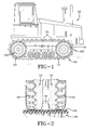
- Figure 1 illustrates one example of a type of vehicle which may utilize the drive tire of the present invention.
- Tire as used herein, means a pneumatic structure mounted upon a wheel which together function as a gear in driving the track of a vehicle.
- Vehicle 10 has an endless rubber track 20 and a drive wheel assembly 40, which further includes a forward set of drive wheel tires 50 and a rear set of drive wheel tires 50'. Two sets of drive wheel tires 50, 50' are axially aligned and mounted in pairs within the endless rubber track 20.
- the outer tread surface 52 of each of the drive wheel tires are in mating engagement with the interior surface 22 of the endless rubber track.
- the interior surface 22 is typically smooth, and includes a plurality of center guide lugs 24, spaced apart on equal intervals.
- Each set of drive tires straddles the center guide lug.
- the center guide lugs 24 are aligned circumferentially along the center of the track 20.
- the center guide lugs function to prevent the endless rubber track from slipping over the ends of the drive wheel tires 50, 50'.
- each center guide lug 24 travels in close proximity between each pair of drive tires 50, 50'.
- the endless rubber track may further include an outer tread surface, which may optionally comprise cross bars or lugs 24 for increased traction.
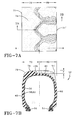
- FIG. 7B a cross-sectional view of the tire 50 of the present invention is shown.
- the tire 50 has a pair of bead cores 54, and a carcass reinforcing structure 56 extending from bead core 54 to bead core 54.
- the carcass reinforcing structure 56 has two or more plies, a first ply 58 and a second ply 60.
- Each ply 58, 60 is reinforced with cords.
- the cords of the first ply 58 are oriented equal but opposite relative to cords of the second ply 60. It is preferable that the cured cords are oriented in an angle of between 30 and 40°.
- Each ply structure 58, 60 as shown has a turn up which wraps about the bead core 54.
- Adjacent to the bead core 54 is a pair of sidewall structures 62.
- the sidewall structures 62 are generally elastomeric and extend from the beads 54 toward the tread 70.
- the shoulders 71 of the tread and sidewall are radiused. While the bias construction is preferred, a radial construction may also be utilized.
- the tread 70 is divided into two tread zones along the circumference of the tire.
- the first tread zone 72 bounded by centerline and shoulder edge 71 of the tread has an outer surface 74 having no lugs or grooves, which is preferably smooth.
- the height of the first tread zone 72 corresponds with, or is symmetrical with, the non-skid depth and undertread of the second tread zone 80.
- the first tread zone 72 comprises in the range of 25% to 55% of the tire section width.
- the first tread zone comprises 35% of the tire section width at line A-A in Figure 7A.
- the first tread zone of the tire abuts the shoulder 71 of the sidewall which also has no grooves and is preferably smooth.
- the first tread zone 72 of the tread is to be located adjacent the guide lug 24 and functions to prevent snagging of the guide lug within the grooves of the tire. Further, the first tread zone 72 provides increased contact area with the track belt, thereby allowing the tire to provide enhanced driving action.
- the second tread zone 80 of the tire is also bounded by the centerline and shoulder edge 71.
- the second tread zone 80 has an inner tread surface 82 and a plurality of tread lugs 84 extending radially outwardly from the inner tread surface 82.
- the tread lugs 84 may comprise any particular shape, however it is preferred that the lugs be shaped so that the tread is non-directional.
- the lugs 84 may comprise a lug head 86 and a shoulder portion 88 connected thereto, wherein the lug head 86 is preferably larger than the shoulder portion 88. More preferably, the width of the lug head 86 is in the range of 1.2 to 1.6 times the width of the shoulder portion 88.
- the lug head may have two or more angled surfaces 89, 91 joined together forming a pointed end 93 which may be optionally located on the equatorial plane of the tire.
- one or more of the grooves 100 extend completely across the second tread zone 80, from a first end to a second end. Even more preferably for soil conditions with heavy debris or mud, the one or more of the grooves 100 extend from the second tread zone 80 into the sidewall 62 of the tire, functioning as soil discharge channels. It is preferred that the grooves 100 are wide, and have a width in the range of 50% to 100% of the lug base width at the shoulder 71, and most preferably, 93% of the shoulder lug base width.
- An optional cleaning groove 110 joins the one or more grooves 100 together and functions to provide multiple pathways to extrude out mud or clear out debris.
- the cleaning groove 110 may be located on the dividing line between the first tread zone and the second tread zone.
- the cleaning groove 110 may be circumferentially straight or in the shape of an undulating groove as shown in Figure 4.
- the cleaning groove 110 preferably forms a pathway around the lug head 84 and joins with the debris clearing grooves 100.
- the net to gross ratio of the second tread zone 80 of the tire is in the range of 40 % to 70%, and most preferably 55%.
- the net to gross ratio of the first tread zone of the tire is in the range of 75% to 100%.
- the overall net to gross ratio of the tire is preferably in the range of 60% to 80%.
- an optional tread shelf or lug reinforcement 120 may be disposed in the one or more soil discharge grooves of the second portion of the tire tread.
- This tread shelf 120 provides additional bracing support for the adjacent lugs and maintains the center of the tire in a more rigid circumferential resistance to hoop deflection.
- the tread shelf may preferably extend above the inner surface of the tread a distance of less than one half inch or 2 cm.
- the tire as described above may be extremely small in section width depending upon the application, and in some cases, having a total section width in the range of 4 inches or 16 cm to 6 inches or 24 cm.
- the tread width may be slightly smaller than the section width of the tire, which means that the entire tractive force of the drive tire must be achieved by the tread over a very narrow width.
- the tire size is 175/95D16
- the lug centerline non-skid distance or lug height h is approximately 0.485 inches (1.2 cm).
- the lug extends radially outward increasing in depth to a maximum lug height of 0.668 inches (1.7 cm) at the shoulder, and the tread shelf itself has a depth of .015 inches (0.4 cm).
- the drive tire has a substantially smooth outer tread surface.
Landscapes
- Engineering & Computer Science (AREA)
- Mechanical Engineering (AREA)
- Tires In General (AREA)
Abstract
Description
- The present invention relates to tracked vehicles such as for agricultural vehicles and the like, and more particularly to a pneumatic drive tire for tracked vehicles.
- In many agricultural applications the use of vehicles having track systems instead of pneumatic tires is becoming increasingly more popular. These track vehicles use an endless track belt, preferably made of elastomeric material reinforced by cords of steel. The belt has a ground engaging tread surface similar to that found on a tire. The primary benefit to a track system is the increased flotation due to the fact that the tracks can bridge a longer surface area, helping to keep the vehicle afloat.
- It is known in the prior art of track vehicles to utilize a pneumatic tire in the drive wheel position. See for example, US-A- 6,386,652. Pneumatic drive tires are well suited for track applications, and have the advantage of increased flotation, reduced need for vehicle suspension, and the ability to frictionally engage the track under adverse soil conditions such as mud and debris. In a typical rubber track application, two pairs of drive tires are used for each track. Each pair of tires straddle a track center guide lug. As the inner part of the tire shoulder is in close proximity to the center guide lug, wear of the tire shoulder can occur. Under adverse conditions, contact between the tire shoulder area with the center lug guide may result in tearing of the tire lugs or "detracking", which occurs when the track disengages from the drive tires.
- The present invention provides a pneumatic drive tire for a tracked vehicle according to claim 1. Dependent claims cover preferred embodiments of the invention.
- The advantages of the present invention will be apparent from the following description when read in conjunction with the accompanying drawings in which:
- Figure 1 is a side elevational view of the work vehicle.
- Figure 2 is a partial cross-sectional view of a preferred drive wheel structure.
- Figure 3 is a perspective view of the drive tire according to the invention.
- Figure 4 is a plane view of the drive tire of Figure 3.
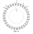
- Figure 5 is a side view of the tire of the present invention according to Figure 3.
- Figure 6 is an enlarged fragmentary view of the tire according to the present invention.
- Figure 7A is an enlarged plan view of the tread of the tire according to the present invention.
- Figure 7B is a cross sectional view of the tire in Figure 7A taken along the
line 7B-7B. - Figure 8 is an enlarged plan view of a second embodiment of a drive tire of the invention.
- Figure 9 is a cross-sectional view of the tire of Figure 8 taken along lines 9-9.
- Figure 1 illustrates one example of a type of vehicle which may utilize the drive tire of the present invention. The term "tire" as used herein, means a pneumatic structure mounted upon a wheel which together function as a gear in driving the track of a vehicle.
Vehicle 10 has anendless rubber track 20 and adrive wheel assembly 40, which further includes a forward set ofdrive wheel tires 50 and a rear set of drive wheel tires 50'. Two sets ofdrive wheel tires 50, 50' are axially aligned and mounted in pairs within theendless rubber track 20. Theouter tread surface 52 of each of the drive wheel tires are in mating engagement with theinterior surface 22 of the endless rubber track. Theinterior surface 22 is typically smooth, and includes a plurality ofcenter guide lugs 24, spaced apart on equal intervals. Each set of drive tires straddles the center guide lug. Thecenter guide lugs 24 are aligned circumferentially along the center of thetrack 20. The center guide lugs function to prevent the endless rubber track from slipping over the ends of thedrive wheel tires 50, 50'. As best shown in Figure 2, each center guide lug 24 travels in close proximity between each pair ofdrive tires 50, 50'. The endless rubber track may further include an outer tread surface, which may optionally comprise cross bars orlugs 24 for increased traction. - In Figure 7B, a cross-sectional view of the
tire 50 of the present invention is shown. Thetire 50 has a pair ofbead cores 54, and acarcass reinforcing structure 56 extending frombead core 54 to beadcore 54. Thecarcass reinforcing structure 56 has two or more plies, a first ply 58 and a second ply 60. Each ply 58, 60 is reinforced with cords. The cords of the first ply 58 are oriented equal but opposite relative to cords of the second ply 60. It is preferable that the cured cords are oriented in an angle of between 30 and 40°. Each ply structure 58, 60 as shown has a turn up which wraps about thebead core 54. Adjacent to thebead core 54 is a pair ofsidewall structures 62. Thesidewall structures 62 are generally elastomeric and extend from thebeads 54 toward thetread 70. Preferably, theshoulders 71 of the tread and sidewall are radiused. While the bias construction is preferred, a radial construction may also be utilized. - The
tread 70 is divided into two tread zones along the circumference of the tire. Thefirst tread zone 72 bounded by centerline andshoulder edge 71 of the tread has anouter surface 74 having no lugs or grooves, which is preferably smooth. The height of thefirst tread zone 72 corresponds with, or is symmetrical with, the non-skid depth and undertread of thesecond tread zone 80. Thefirst tread zone 72 comprises in the range of 25% to 55% of the tire section width. Preferably, the first tread zone comprises 35% of the tire section width at line A-A in Figure 7A. The first tread zone of the tire abuts theshoulder 71 of the sidewall which also has no grooves and is preferably smooth. Thefirst tread zone 72 of the tread is to be located adjacent theguide lug 24 and functions to prevent snagging of the guide lug within the grooves of the tire. Further, thefirst tread zone 72 provides increased contact area with the track belt, thereby allowing the tire to provide enhanced driving action. - The
second tread zone 80 of the tire is also bounded by the centerline andshoulder edge 71. Thesecond tread zone 80 has aninner tread surface 82 and a plurality oftread lugs 84 extending radially outwardly from theinner tread surface 82. Thetread lugs 84 may comprise any particular shape, however it is preferred that the lugs be shaped so that the tread is non-directional. Thelugs 84 may comprise alug head 86 and ashoulder portion 88 connected thereto, wherein thelug head 86 is preferably larger than theshoulder portion 88. More preferably, the width of thelug head 86 is in the range of 1.2 to 1.6 times the width of theshoulder portion 88. As shown in the drawing as merely one example of thelug shape 86, the lug head may have two or moreangled surfaces pointed end 93 which may be optionally located on the equatorial plane of the tire. - Disposed between the tread lugs 84 are debris clearing voids or
grooves 100. Preferably, one or more of thegrooves 100 extend completely across thesecond tread zone 80, from a first end to a second end. Even more preferably for soil conditions with heavy debris or mud, the one or more of thegrooves 100 extend from thesecond tread zone 80 into thesidewall 62 of the tire, functioning as soil discharge channels. It is preferred that thegrooves 100 are wide, and have a width in the range of 50% to 100% of the lug base width at theshoulder 71, and most preferably, 93% of the shoulder lug base width. - An
optional cleaning groove 110 joins the one ormore grooves 100 together and functions to provide multiple pathways to extrude out mud or clear out debris. The cleaninggroove 110 may be located on the dividing line between the first tread zone and the second tread zone. The cleaninggroove 110 may be circumferentially straight or in the shape of an undulating groove as shown in Figure 4. The cleaninggroove 110 preferably forms a pathway around thelug head 84 and joins with thedebris clearing grooves 100. - The net to gross ratio of the
second tread zone 80 of the tire is in the range of 40 % to 70%, and most preferably 55%. The net to gross ratio of the first tread zone of the tire is in the range of 75% to 100%. The overall net to gross ratio of the tire is preferably in the range of 60% to 80%. - As shown in Figure 8, an optional tread shelf or
lug reinforcement 120 may be disposed in the one or more soil discharge grooves of the second portion of the tire tread. Thistread shelf 120 provides additional bracing support for the adjacent lugs and maintains the center of the tire in a more rigid circumferential resistance to hoop deflection. The tread shelf may preferably extend above the inner surface of the tread a distance of less than one half inch or 2 cm. - The tire as described above, may be extremely small in section width depending upon the application, and in some cases, having a total section width in the range of 4 inches or 16 cm to 6 inches or 24 cm. The tread width may be slightly smaller than the section width of the tire, which means that the entire tractive force of the drive tire must be achieved by the tread over a very narrow width.
- In a first example of the tire, the tire size is 175/95D16, the lug centerline non-skid distance or lug height h is approximately 0.485 inches (1.2 cm). The lug extends radially outward increasing in depth to a maximum lug height of 0.668 inches (1.7 cm) at the shoulder, and the tread shelf itself has a depth of .015 inches (0.4 cm). In yet another embodiment of the invention, the drive tire has a substantially smooth outer tread surface.
Claims (10)
- A pneumatic drive tire for a tracked vehicle, said drive tire (50) comprising: a pair of annular beads (54), a carcass reinforcing structure (56), and an elastomeric sidewall (62) extending radially outwardly from each bead adjacent the carcass reinforcing structure to a radially outer tread (70), wherein the tread (70) has a first tread zone (72) and a second tread zone (80), wherein said first zone (72) comprises a smooth outer surface and/or has no lugs and no grooves, and wherein said second tread zone (80) comprises a plurality of lugs (84) and a plurality of grooves (100).
- The pneumatic drive tire of claim 1, wherein said first tread zone (72) is in the range of 25% to 55% of the tread width.
- The pneumatic drive tire of claim 1 or 2, wherein said first tread zone (72) has a net to gross ratio in the range of 75% to 100%, and wherein said second tread zone (80) has a net to gross ratio in the range of 40% to 70%.
- The pneumatic drive tire of at least one of the previous claims, wherein said tread (70) further comprises radiused outer edges joining the sidewalls (62) of the tire.
- The pneumatic drive tire of at least one of the previous claims, wherein said tread (70) is radiused from sidewall to sidewall.
- The pneumatic drive tire of at least one of the previous claims, wherein said second tread zone (80) further comprises a circumferential groove (110).
- The pneumatic drive tire of at least one of the previous claims, wherein said second tread zone (80) further comprises a circumferential groove (110) joining with at least one of said plurality of grooves (100).
- The pneumatic drive tire of at least one of the previous claims, wherein said second tread zone (80) further comprises a circumferential groove (110) located on the centerline of said tire (50), said circumferential groove joining with each of said plurality of grooves (100) to clear debris and mud from the tire.
- The pneumatic drive tire of at least one of the previous claims, wherein a tread shelf extends radially outwardly from an inner tread surface (82) of at least one groove (100).
- The pneumatic drive tire of at least one of the previous claims, wherein each of said first and second tread zones (72, 80) extends from a shoulder edge to the centerline of the tread.
Applications Claiming Priority (1)
| Application Number | Priority Date | Filing Date | Title |
|---|---|---|---|
| US10/888,205 US7637296B2 (en) | 2004-07-09 | 2004-07-09 | Pneumatic driver tire for tracked vehicle |
Publications (1)
| Publication Number | Publication Date |
|---|---|
| EP1623847A1 true EP1623847A1 (en) | 2006-02-08 |
Family
ID=34940255
Family Applications (1)
| Application Number | Title | Priority Date | Filing Date |
|---|---|---|---|
| EP05105888A Withdrawn EP1623847A1 (en) | 2004-07-09 | 2005-06-30 | Pneumatic driver tire for tracked vehicle |
Country Status (4)
| Country | Link |
|---|---|
| US (1) | US7637296B2 (en) |
| EP (1) | EP1623847A1 (en) |
| AU (1) | AU2005202798A1 (en) |
| CA (1) | CA2508902C (en) |
Families Citing this family (2)
| Publication number | Priority date | Publication date | Assignee | Title |
|---|---|---|---|---|
| EP2096021B1 (en) * | 2008-02-27 | 2010-06-02 | Solideal Holding Sa | Rubber crawler, method for making rubber crawler and vehicle provided with rubber crawler |
| US8177538B1 (en) | 2011-03-21 | 2012-05-15 | Bridgestone Americas Tire Operations, Llc | Tire mold having sidewall structure |
Citations (3)
| Publication number | Priority date | Publication date | Assignee | Title |
|---|---|---|---|---|
| DE230523C (en) * | 1908-01-10 | |||
| US3880218A (en) * | 1972-02-16 | 1975-04-29 | Gen Tire & Rubber Co | Asymmetrical construction tire |
| UST973007I4 (en) * | 1978-02-23 | 1978-08-01 | Caterpillar Tractor Co. | Replaceable tire tread belt |
Family Cites Families (19)
| Publication number | Priority date | Publication date | Assignee | Title |
|---|---|---|---|---|
| US2534869A (en) * | 1945-11-19 | 1950-12-19 | Bonnie G Jones | Motor vehicle tire |
| US3107128A (en) * | 1961-05-12 | 1963-10-15 | George W Ruane | Removable track and tire assembly for a vehicle |
| IT1087461B (en) * | 1977-09-23 | 1985-06-04 | Pirelli | IMPROVEMENT OF TIRES FOR CARS |
| US5363936A (en) * | 1983-12-20 | 1994-11-15 | Caterpillar Inc. | Frictionally driven belted work vehicle |
| US4769203A (en) * | 1984-06-18 | 1988-09-06 | Bridgestone Corporation | Method of manufacturing pneumatic tires by vulcanization building |
| JPS61249807A (en) * | 1985-04-27 | 1986-11-07 | Bridgestone Corp | Pneumatic tire for rough road running |
| JPS638003A (en) * | 1986-06-30 | 1988-01-13 | Yokohama Rubber Co Ltd:The | Pneumatic tyre |
| JP2901244B2 (en) * | 1988-01-22 | 1999-06-07 | 株式会社ブリヂストン | Combination of car and tire |
| DE9000204U1 (en) * | 1990-01-10 | 1991-02-21 | Uniroyal Englebert Reifen GmbH, 5100 Aachen | Pneumatic vehicle tires |
| US5327952A (en) * | 1991-03-08 | 1994-07-12 | The Goodyear Tire & Rubber Company | Pneumatic tire having improved wet traction |
| JPH05155204A (en) * | 1991-12-05 | 1993-06-22 | Chikusui Canycom:Kk | Pneumatic tire |
| US5261474A (en) * | 1992-12-31 | 1993-11-16 | The Goodyear Tire & Rubber Company | Earthmover tire |
| US5323824A (en) * | 1993-03-11 | 1994-06-28 | The Goodyear Tire & Rubber Company | Tire/vehicle system |
| DE4419295A1 (en) * | 1994-06-01 | 1995-12-07 | Sp Reifenwerke Gmbh | Pair of twin tires |
| US6073668A (en) * | 1997-04-16 | 2000-06-13 | Sumitomo Rubber Industries, Inc. | Vehicle tire including tread portion having profile |
| USD413557S (en) | 1998-09-02 | 1999-09-07 | The Goodyear Tire & Rubber Company | Traction tire |
| US6386652B1 (en) * | 1998-09-02 | 2002-05-14 | The Goodyear Tire & Rubber Company | Pneumatic driver tire for tracked vehicle |
| US6761196B2 (en) * | 2000-01-26 | 2004-07-13 | Bridgestone Corporation | Pneumatic tire having lug grooves |
| US7198337B2 (en) * | 2003-01-23 | 2007-04-03 | Kinze Manufacturing, Inc. | Wheel for belted track vehicles |
-
2004
- 2004-07-09 US US10/888,205 patent/US7637296B2/en not_active Expired - Fee Related
-
2005
- 2005-05-31 CA CA2508902A patent/CA2508902C/en not_active Expired - Fee Related
- 2005-06-27 AU AU2005202798A patent/AU2005202798A1/en not_active Abandoned
- 2005-06-30 EP EP05105888A patent/EP1623847A1/en not_active Withdrawn
Patent Citations (3)
| Publication number | Priority date | Publication date | Assignee | Title |
|---|---|---|---|---|
| DE230523C (en) * | 1908-01-10 | |||
| US3880218A (en) * | 1972-02-16 | 1975-04-29 | Gen Tire & Rubber Co | Asymmetrical construction tire |
| UST973007I4 (en) * | 1978-02-23 | 1978-08-01 | Caterpillar Tractor Co. | Replaceable tire tread belt |
Also Published As
| Publication number | Publication date |
|---|---|
| CA2508902A1 (en) | 2006-01-09 |
| AU2005202798A1 (en) | 2006-02-02 |
| US20060005907A1 (en) | 2006-01-12 |
| CA2508902C (en) | 2012-07-17 |
| US7637296B2 (en) | 2009-12-29 |
Similar Documents
| Publication | Publication Date | Title |
|---|---|---|
| US3457981A (en) | Pneumatic tires | |
| US6920906B2 (en) | Pneumatic tire with sidewall projections | |
| CA2129216C (en) | A non-directional pneumatic tire for use on agricultural tractors and other like vehicles | |
| US6386652B1 (en) | Pneumatic driver tire for tracked vehicle | |
| EP3116770B1 (en) | Vehicle track assembly having tapered wheels | |
| US4574857A (en) | Tractor tire tread | |
| JPH0789303A (en) | Pneumatic tire | |
| EP1544000B1 (en) | Low net to gross off-the-road tire | |
| EP2934919B1 (en) | Tyre for heavy load vehicle wheels | |
| CN102405170A (en) | Rubber track | |
| JP2013523520A (en) | Tires for heavy duty vehicle wheels | |
| US4570689A (en) | Bicycle tire tread | |
| CA2508902C (en) | Pneumatic driver tire for tracked vehicle | |
| CN103328231B (en) | agricultural tire | |
| US6957676B2 (en) | Tire for a vehicle wheel including at least two circumferential series of inclined incisions delimiting at least three rows of blocks | |
| CN102741065A (en) | Agricultural tyre | |
| JPH0717214A (en) | Pneumatic radial tires for heavy loads | |
| GB1587963A (en) | Pneumatic tyres | |
| EP1109680B1 (en) | Pneumatic driver tire for tracked vehicle | |
| CN102036838A (en) | Heavy-load vehicle tire | |
| JP2005067246A (en) | Heavy duty tire | |
| US20220118797A1 (en) | Tread for an Agricultural Vehicle | |
| GB2048800A (en) | An improved endless flexible track system for a vehicle | |
| US20240092437A1 (en) | Resilient wheel with low-friction and wear resistant sidewall and track system having same | |
| KR100821549B1 (en) | Heavy-duty pneumatic tires with belt layer for improved wear resistance |
Legal Events
| Date | Code | Title | Description |
|---|---|---|---|
| PUAI | Public reference made under article 153(3) epc to a published international application that has entered the european phase |
Free format text: ORIGINAL CODE: 0009012 |
|
| AK | Designated contracting states |
Kind code of ref document: A1 Designated state(s): AT BE BG CH CY CZ DE DK EE ES FI FR GB GR HU IE IS IT LI LT LU MC NL PL PT RO SE SI SK TR |
|
| AX | Request for extension of the european patent |
Extension state: AL BA HR LV MK YU |
|
| 17P | Request for examination filed |
Effective date: 20060808 |
|
| AKX | Designation fees paid |
Designated state(s): DE FR IT |
|
| 17Q | First examination report despatched |
Effective date: 20110719 |
|
| STAA | Information on the status of an ep patent application or granted ep patent |
Free format text: STATUS: THE APPLICATION IS DEEMED TO BE WITHDRAWN |
|
| 18D | Application deemed to be withdrawn |
Effective date: 20111130 |