EP1623632A2 - Peeling apparatus and associated methods - Google Patents
Peeling apparatus and associated methods Download PDFInfo
- Publication number
- EP1623632A2 EP1623632A2 EP05024612A EP05024612A EP1623632A2 EP 1623632 A2 EP1623632 A2 EP 1623632A2 EP 05024612 A EP05024612 A EP 05024612A EP 05024612 A EP05024612 A EP 05024612A EP 1623632 A2 EP1623632 A2 EP 1623632A2
- Authority
- EP
- European Patent Office
- Prior art keywords
- peeling
- peeling apparatus
- cleaning solution
- abrasive rollers
- rollers
- Prior art date
- Legal status (The legal status is an assumption and is not a legal conclusion. Google has not performed a legal analysis and makes no representation as to the accuracy of the status listed.)
- Withdrawn
Links
Images




Classifications
-
- A—HUMAN NECESSITIES
- A23—FOODS OR FOODSTUFFS; TREATMENT THEREOF, NOT COVERED BY OTHER CLASSES
- A23N—MACHINES OR APPARATUS FOR TREATING HARVESTED FRUIT, VEGETABLES OR FLOWER BULBS IN BULK, NOT OTHERWISE PROVIDED FOR; PEELING VEGETABLES OR FRUIT IN BULK; APPARATUS FOR PREPARING ANIMAL FEEDING- STUFFS
- A23N15/00—Machines or apparatus for other treatment of fruits or vegetables for human purposes; Machines or apparatus for topping or skinning flower bulbs
- A23N15/02—Machines or apparatus for other treatment of fruits or vegetables for human purposes; Machines or apparatus for topping or skinning flower bulbs for stemming, piercing, or stripping fruit; Removing sprouts of potatoes
-
- A—HUMAN NECESSITIES
- A23—FOODS OR FOODSTUFFS; TREATMENT THEREOF, NOT COVERED BY OTHER CLASSES
- A23N—MACHINES OR APPARATUS FOR TREATING HARVESTED FRUIT, VEGETABLES OR FLOWER BULBS IN BULK, NOT OTHERWISE PROVIDED FOR; PEELING VEGETABLES OR FRUIT IN BULK; APPARATUS FOR PREPARING ANIMAL FEEDING- STUFFS
- A23N7/00—Peeling vegetables or fruit
- A23N7/02—Peeling potatoes, apples or similarly shaped vegetables or fruit
-
- B—PERFORMING OPERATIONS; TRANSPORTING
- B24—GRINDING; POLISHING
- B24B—MACHINES, DEVICES, OR PROCESSES FOR GRINDING OR POLISHING; DRESSING OR CONDITIONING OF ABRADING SURFACES; FEEDING OF GRINDING, POLISHING, OR LAPPING AGENTS
- B24B25/00—Grinding machines of universal type
Definitions
- This invention relates to the field of food processing, and more particularly, to apparatus and methods for peeling vegetables and fruits.
- U. S. Patent No. 3,745,914 to Wallace discloses a single chamber fruit and vegetable peeler including a frame, a plurality of abrasive rollers carried by the frame and arranged in an arcuate pattern, and a drive motor and gears coupled to the rollers.
- the abrasive rollers are provided in lengthwise segments to facilitate replacement of a damaged section without requiring replacement of an entire roller.
- Action of the rollers advances the fruit or vegetables from an intake to a discharge.
- a rinsing system is provided to wash material from the rollers.
- the vegetables or fruit are subjected to a tumbling action within the peeling chamber.
- the amount of peeling is controlled by a height of a gate at the discharge.
- U. S. Patent No. 4,519,305 to Vanosdall discloses a similar apparatus wherein an auger extends only partway into the chamber from the discharge.
- U. S. Patent No. 5,858,429 also to Wallace discloses a similar apparatus which includes an auger at a feed hopper, and a rotatable tumbler including rotating paddles within the peeling chamber. This patent also discloses a vision analysis system to evaluate the degree of peeling and adjust the various parameters to provide a desired degree of peeling.
- U. S. Patent Nos. 4,237,782 to Bichel and 4,827,836 to Nacheh disclose peeling apparatus wherein the abrasive rollers are driven by individual hydraulic motors.
- U. S. Patent Nos. 5,780,088 and 5,989,614, both to Zittel disclose a peeler that includes individual electric motors to drive each roller. The rollers can be operated at different speeds or in different directions. An auger which extends through the peeling chamber, may also be controlled by an electric motor.
- a dual peeling or washing chamber apparatus was offered by Vanmark Corporation under the model designation Series 2800.
- the apparatus included two side-by-side chambers wherein the auger screws rotated in a same direction. Accordingly, the abrasive rollers extended around an arc further upward on a same side at the center of the apparatus.
- this arrangement places a number of abrasive rollers in the interior of the peeling apparatus which makes maintenance more difficult for these interior rollers and associated portions. Such an arrangement also increases the needed width of the machine, thereby complicating its placement with other processing equipment.
- a high capacity peeling apparatus that includes dual peeling chambers and wherein feeders in the form of augers rotate in opposite directions.
- the peeling apparatus may comprise a frame, and first and second peeling chambers carried by the frame in side-by-side relation.
- the first peeling chamber includes a first set of abrasive rollers and a first auger adjacent thereto
- the second peeling chamber includes a second set of abrasive rollers and a second auger adjacent thereto.
- the first and second augers comprise respective helical flights oriented in opposite helical directions.
- the peeling apparatus also includes a drive for driving the first and second augers in opposite rotational directions.
- the first set of abrasive rollers may be aligned along a first arc
- the second set of abrasive rollers may be aligned along a second arc being a mirror image of the first arc.
- the first and second arcs preferably each extend higher along outsides of the peeling apparatus. In other words, the number of rollers along the inner portion of the apparatus is reduced in favor of more rollers along the more accessible outer portion.
- the peeling apparatus may further comprise a set of mounts including flange bearings and being removably connected to a first end of the frame adjacent at least one first roller opening, the sets of abrasive rollers having first ends rotatably supported by the flange bearings.
- the mounts permit the abrasive rollers to be installable or removable through roller openings upon removal of the respective mounts from the frame.
- the peeling apparatus may also include a set of roller drive motors for respective abrasive rollers that are also carried by respective mounts. Accordingly, the motors and rollers can be readily removed and installed, such as for maintenance.
- Each mount may have a trapezoidal shape, and the mounts may be arranged in side-by-side relation to define an arc.
- the peeling chambers may extend generally horizontally.
- the flange bearings used in the mounts may be more desirable than pillow block bearings which are often used in similar peeling apparatus.
- a feeder may also be provided for feeding fruit or vegetables adjacent the set of abrasive rollers so that the first end defines an intake end. Accordingly, the mounts permit installation and removal of the abrasive rollers from the intake end.
- the number of abrasive rollers in each set thereof may be greater than eight.
- the total number of abrasive rollers in the first and second sets may be greater than sixteen.
- a second set of flange bearings may be carried by a second end of the frame for respective second ends of the abrasive rollers.
- each of the second set of flange bearings may comprise a two fastener flange bearing having a generally oval footprint. This permits each flange bearing of the second set of flange bearings to be canted at an angle and nested into an adjacent flange bearing. Since the second end is typically the discharge end, this relatively compact arrangement of flange bearings permits the fruit or vegetables to be readily discharged.
- the peeling apparatus may comprise a cleaning solution delivery system for contacting surfaces of the peeling chamber with a cleaning solution.
- This cleaning solution delivery system is connected to a common cleaning solution delivery system that extends within the processing plant, and which is shared with other processing apparatus.
- the peeling apparatus may include a cleaning solution collection system for collecting cleaning solution after contacting surfaces of the peeling chamber.
- This cleaning solution collection system may also be connected to a common cleaning solution collection system in the processing plant which is also shared with other processing apparatus.
- One method aspect of the invention relates to peeling fruit or vegetables.
- the method comprises providing first and second-peeling chambers carried by a frame in side-by-side relation, with the first peeling chamber comprising a first set of abrasive rollers and a first auger adjacent thereto, and with the second peeling chamber comprising a second set of abrasive rollers and a second auger adjacent thereto.
- the first and second augers comprise respective helical flights oriented in opposite helical directions.
- the method also includes driving the first and second augers in opposite rotational directions to thereby advance the objects along the first and second sets of abrasive rollers respectively.
- Still another method aspect of the invention relates to a method for processing fruit or vegetables using a plurality of processing apparatus and comprising at least one peeling apparatus.
- This method comprises providing a common cleaning solution delivery system connected to the processing apparatus, and providing the peeling apparatus with a cleaning solution delivery system connected to the common cleaning solution delivery system.
- the method may include providing a common cleaning solution collection system connected to the processing apparatus, and providing the peeling apparatus with a cleaning solution collection system connected to the common cleaning solution collection system.
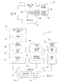
- the peeling apparatus 20 may be part of an overall fruit or vegetable processing system 25 that may include other processing apparatus 21, 22 as schematically illustrated.
- these other processing apparatus 21, 22 may also be connected to a common plant cleaning solution system 23 including a cleaning solution supply and associated interconnecting piping.
- these other processing apparatus 21, 22 may also be connected to a common plant cleaning solution collection system 24 including a drain, sump or collection vessel and interconnecting piping as will be appreciated by those skilled in the art.
- the peeling apparatus 20 may include the lower collection pan 29 and the outlet port 31 in communication therewith which define the cleaning solution collection system for the peeling apparatus, and which may be coupled to the common plant cleaning solution collection system 24.
- the cleaning solution from the peeling apparatus 20 may also be recycled and used again for cleaning the peeler and/or any of the other processing apparatus 21, 22.
- the cleaning solution from the common plant cleaning solution delivery system 23 may be distributed or sprayed on interior portions of the peeling apparatus 20 using the schematically illustrated nozzles 35 (FIG. 4).
- the peeling apparatus 25 illustratively includes two generally horizontally extending, side-by-side peeling chambers 26a, 26b, but many of the features and components thereof may also be used in a single peeling chamber apparatus, and/or in a peeling apparatus arranged at an angle other than horizontal as will be readily appreciated by those skilled in the art.
- the peeling apparatus 20 is also illustratively fed fruit or vegetables from one or more upstream devices, schematically illustrated in FIG. 1 by the fruit/vegetable supply 27.
- the peeling apparatus 20 also includes a controller 28 connected to the various motors and other equipment as will be described in greater detail below.
- the peeling apparatus 20 may be used for many peeling operations to be performed typically on fruit or vegetables.
- the peeling apparatus 20 may be used to extract oil from the peels of citrus fruit as disclosed in parent U. S. Patent No. 6,426,107.
- the peeling apparatus 20 may be used for peeling potatoes, and other fruit and vegetables as will be appreciated by those skilled in the art.
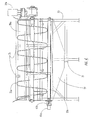
- the peeling apparatus 20 illustratively includes a frame 30 which carries the first and second peeling chambers 26a, 26b in side-by-side relation.
- the first peeling chamber 26a includes a first set of abrasive rollers 32a and a first auger 33a adjacent thereto.
- the second peeling chamber 26 comprises a second set of abrasive rollers 32b and a second auger 33b adjacent thereto.
- Each auger 33a, 33b has a respective electric drive motor 34a, 34b connected thereto.
- a discharge opening 37a, 37b is provided at the discharge end of each peeling chamber 26a, 26b as shown perhaps best in FIGS. 1 and 4.
- the discharge openings 37 are illustratively arcuate in shape and offset to the respective outer sides.
- a common intake opening 39 (FIG. 2) is provided at the intake end to receive the fruit or vegetables therein.
- the first and second augers 33a, 33b include respective helical flights oriented in opposite helical directions.
- the drive motors 34a, 34b drive the first and second augers 33a, 33b in opposite rotational directions.
- the drive motors 34a, 34b define a drive for the augers 33a, 33b.
- the fruit or vegetables in each peeling chamber 26a, 26b is advanced in parallel from the intake to the discharge end of the peeling apparatus 20.
- the first set of abrasive rollers 32a is aligned along a first arc
- the second set of abrasive rollers 32b is aligned along a second arc being a mirror image of the first arc.
- the first and second arcs each extend higher along outsides of the peeling apparatus 20. This may be accommodated since rotation of the augers 33a, 33b tends to cause the fruit to ride up toward the outside as will be appreciated by those skilled in the art.
- This arrangement of rollers provides a number of advantages, particularly in that more rollers are accessible from the exterior of the peeling apparatus 20, rather than being positioned on the less accessible interior as will be appreciated by those skilled in the art.
- the number of abrasive rollers 32a, 32b in each of the first and second sets may be greater than eight. In the illustrated embodiment, twelve rollers are provided in each set. A combined or total number of abrasive rollers 32a, 32b in both of the first and second sets is also preferably greater than sixteen. In the illustrated peeling apparatus 20 the total number of rollers is twenty-four. The larger number of rollers may provide a greater throughput in a smaller machine footprint. Accordingly, the peeling apparatus 20 may be installed or retrofitted into a relatively small space.
- each peeling chamber 26a, 26b illustratively includes a set of motors 40a, 40b and associated mounts 41a, 41b for the abrasive rollers.
- These motors 40a, 40b and mounts 41a, 41b are illustratively carried by the intake end, accordingly, the fruit or vegetables can more readily pass out of the discharge openings unencumbered by the motors and mounts as will be appreciated by those skilled in the art.
- the frame 30 includes a roller opening 45a adjacent the intake end.
- the roller opening 45a may be an arcuately shaped slotted opening for the set of rollers as in the illustrated embodiment, or individual openings could be provided for each roller as will be appreciated by those skilled in the art.
- the mount 41a is also connected to the intake end adjacent the roller opening 45a, and this mount carries the intake end of the abrasive roller 32a as well as the motor 40a.
- the mount 41 a permits the abrasive roller 32a to be installable or removable through the roller opening 45a upon removal of the mount 41a from the frame 30.
- the mount 41 a also permits the roller drive motor 40a to be separately removed, such as for service or replacement.
- the abrasive roller 32a illustratively comprises an elongate body portion 60a having an abrasive outer surface as will be described in greater detail below, and an intake mounting stub 61 a and a discharge mounting stub 62a (FIG. 7) permanently affixed to respective opposing ends of elongate body portion.
- Each mounting stub may include a body portion received within an open end of the elongate body portion 60a, and may also include an integrally formed shaft extending outwardly therefrom. Other similar constructions are also possible.
- the mounting stubs 61 a, 62a are preferably permanently affixed to the ends of the elongate body portion 60a to provide for higher rotational speeds with less vibration and resonance as will be appreciated by those skilled in the art.
- the mounting stubs 61a, 62a may be permanently affixed by welding, although similar techniques are also contemplated by the present invention.
- the mount 41 a illustratively includes a base plate 46a covering overlying the opening 45a and secured to the frame 30.
- a flange bearing 47a is carried by the base plate 46a and rotatably supports the intake mounting stub 61a at the end of the abrasive roller 32a.
- the mount 41a also illustratively includes the motor standoff 50a also carried by the base plate 46a and which is coaxial with the end of the mounting stub 61a and output shaft 53a of the motor 40a.
- the output shaft 53a of the motor 40a is connected to the end of the mounting stub 61a via a flexible coupling 51a which may also permit higher rotational speeds for the abrasive roller 32a by reducing vibration.
- the schematically illustrated motor 40a may include an electric or hydraulic actuator directly coupled to the output shaft 53a, or an intervening gearbox may be provided to produce a desired rotational speed of the abrasive roller 32a as will be appreciated by those skilled in the art.
- the motor 40a is illustratively connected to a motor mounting plate 52a which, in turn, is carried by the end of the motor standoff 50a.
- Other equivalent mounting arrangements are also contemplated by the invention.
- the individual motors may be replaced by a common motor and associated drive train for driving the sets of rollers.
- the mounts 41a, 41b, and, more particularly, the base plates thereof may have a trapezoidal shape. Accordingly, when the mounts 41 a, 41b are arranged in side-by-side relation, the mounts define an arc.
- respective sets of flange bearings 70a, 70b are provided at the discharge end of the peeling apparatus for each of the peeling chambers 26a, 26b.
- Each flange bearing 70a is illustratively provided by a flange bearing having a generally oval footprint with first and second fastener openings adjacent opposing ends of the footprint and which, in turn, receive respective first and second fasteners 72a to secure the flange bearing in place.
- the flange bearing 70a of the mount rotatably supports the discharge mounting stub 62a of the abrasive roller 32a.
- each flange bearing 70a with its generally oval footprint may be readily canted at an angle and nested into an adjacent flange bearing.
- pillow block bearings for example, may be difficult to accurately position and may take up additional space.
- the flange bearings 70a, 70b of the peeling apparatus 20 provide a very compact arrangement adjacent the discharge openings 37a, 37b so that the fruit or vegetables may be easily discharged therefrom.
- the abrasive roller 32a includes an elongate body portion 60a, preferably in the form of an elongate tube to thereby reduce overall weight.
- the tubular shape may be readily and accurately formed by precision centerless grinding techniques as will be appreciated by those skilled in the art.
- Mounting stubs 61 a, 62a are preferably welded to opposing ends of the tubular elongate body portion 60a as described above, and an abrasive surface is formed on the outer surface portion of the elongate body portion.
- the abrasive outer surface may be manufactured by pressing the outer roller surface against a shaping or die surface to form a pattern of knurls, similar to a 3.9T/cm (#10TPI) knurl.
- the knurls may be integrally formed into the surface of the elongate body portion 60a.
- the illustrated knurl 75a may define a peak height of about 1.27 mm (0.050 inches) with a tolerance of about +0.00 and -0.51 mm (+0.00 and -0.020 inches).
- the abrasive roller 32a may have a diameter of about 99 to 102 mm (3.9 to 4.0 inches), although other sizes are also possible.
- the knurl 75a may have a leading edge portion 76a that is steeper than the adjacent trailing edge portion 77a.
- the leading edge portion 76a may define an angle a of about a thirty degrees from a line normal to the surface.
- the trailing edge portion 77a may define an angle of about sixty degrees from a line normal to the surface. Other angles are also possible. The steeper angle of the leading edge portion 76a may provide an extended wear life, and reduce the need for maintenance. In some embodiments, all of the knurls may have a same shape, although other embodiments may benefit from different shaped knurls.
- a wear-resistant surface coating 80a may be applied to cover the base metal of the elongate body portion 60a.
- the elongate body portion 60a may comprise steel or aluminum, and the surface coating 80a may comprise cobalt, chromium, tungsten, nickel, or alloys thereof.
- Stellite® may be used as the coating 80a and it is an alloy family containing cobalt, chromium, tungsten and other elements as will be readily appreciated by those skilled in the art.
- the base metal of the abrasive roller 32a may not require a coating.
- stainless steel may not require a protective coating.
- a mild steel base metal may be combined with the protective coating 80a as will be appreciated by those skilled in the art.
- the peeling apparatus 20 includes a set of abrasive rollers 32a arranged to define a peeling chamber 26a, and roller drive motors 40a as explained in detail above.
- a feeder 85a is provided for controllably feeding fruit or vegetables adjacent the abrasive rollers.
- a sensor 86a is associated with at least one roller drive motor 40a for sensing a load thereon.
- the sensor 86a may be associated with one or more lower rollers to more accurately sense the load, although sensors may be provided for all of the motors as will be appreciated by those skilled in the art.
- the controller 28 is illustratively connected to the sensor 86a and feeder 85a for controlling the feeder based upon the sensor. Accordingly, the feeder 85a can be controlled based upon the sensed load on the abrasive roller 32a.
- the controller 28 may increase the feed rate of the feeder 85a based upon an increase in sensed load, and conversely decrease the feed rate based upon a decrease in sensed load.
- the controller 28 may also control one more of the roller drive motors 40a based upon the sensed load.
- the feeder 85a may comprise an input conveyor 90a upstream of the set of abrasive rollers.
- the feeder may include the auger 33a adjacent the set of abrasive rollers.
- the feeder 85a may include at least one of an intake gate 91a and a discharge gate 92a, and with or without the input conveyor and/or auger.
- the sensor 86a may comprise a torque sensor for sensing a torque delivered by the roller drive motor 40a.
- the roller drive motor 40a may be a hydraulic motor 95a, and the sensor 86a may be a hydraulic pressure sensor 96a.
- the roller drive motor 40a may comprise a roller drive electric motor 94a. Accordingly, for this class of embodiments, the torque sensor may thus comprise an electrical power sensor 97a.
- the controller 28 itself may include a processor 100a and various input/output devices 101a connected thereto.
- the input/output devices 101 a may include an operator CRT display or other indicators, as well as a keyboard or other input devices as will be appreciated by those skilled in the art.
- the controller 28 may provide a range of from full automatic to full manual control as will also be appreciated by those skilled in the art.
Landscapes
- Engineering & Computer Science (AREA)
- Life Sciences & Earth Sciences (AREA)
- Chemical & Material Sciences (AREA)
- Food Science & Technology (AREA)
- Polymers & Plastics (AREA)
- Mechanical Engineering (AREA)
- Apparatuses For Bulk Treatment Of Fruits And Vegetables And Apparatuses For Preparing Feeds (AREA)
- Finish Polishing, Edge Sharpening, And Grinding By Specific Grinding Devices (AREA)
- Processing Of Stones Or Stones Resemblance Materials (AREA)
Abstract
Description
- This invention relates to the field of food processing, and more particularly, to apparatus and methods for peeling vegetables and fruits.
- It is common in many food processing applications to require the peeling of the outer skin of fruits or vegetables. Potatoes, in particular, are very often so processed by passing the potatoes against a set of rotating abrasive rollers. Fruit may also be similarly processed. For example, U. S. Patent No. 2,605,798 to Boswell discloses a citrus fruit peeler including a pair of abrading rollers and an auger screw which advances the citrus along the rollers.
- Along these lines, U. S. Patent No. 3,745,914 to Wallace discloses a single chamber fruit and vegetable peeler including a frame, a plurality of abrasive rollers carried by the frame and arranged in an arcuate pattern, and a drive motor and gears coupled to the rollers. The abrasive rollers are provided in lengthwise segments to facilitate replacement of a damaged section without requiring replacement of an entire roller. Action of the rollers advances the fruit or vegetables from an intake to a discharge. A rinsing system is provided to wash material from the rollers. The vegetables or fruit are subjected to a tumbling action within the peeling chamber. The amount of peeling is controlled by a height of a gate at the discharge.
- U. S. Patent No. 4,519,305 to Vanosdall discloses a similar apparatus wherein an auger extends only partway into the chamber from the discharge. U. S. Patent No. 5,858,429 also to Wallace discloses a similar apparatus which includes an auger at a feed hopper, and a rotatable tumbler including rotating paddles within the peeling chamber. This patent also discloses a vision analysis system to evaluate the degree of peeling and adjust the various parameters to provide a desired degree of peeling.
- U. S. Patent Nos. 4,237,782 to Bichel and 4,827,836 to Neidigh disclose peeling apparatus wherein the abrasive rollers are driven by individual hydraulic motors. U. S. Patent Nos. 5,780,088 and 5,989,614, both to Zittel disclose a peeler that includes individual electric motors to drive each roller. The rollers can be operated at different speeds or in different directions. An auger which extends through the peeling chamber, may also be controlled by an electric motor.
- To increase capacity, a dual peeling or washing chamber apparatus was offered by Vanmark Corporation under the model designation Series 2800. The apparatus included two side-by-side chambers wherein the auger screws rotated in a same direction. Accordingly, the abrasive rollers extended around an arc further upward on a same side at the center of the apparatus. Unfortunately, this arrangement places a number of abrasive rollers in the interior of the peeling apparatus which makes maintenance more difficult for these interior rollers and associated portions. Such an arrangement also increases the needed width of the machine, thereby complicating its placement with other processing equipment.
- Conventional peeling machines have also generally suffered from poor maintainability because of the mounting of rollers and respective motors. Accessing and replacing such components may be especially difficult since other processing equipment may be placed relatively close to the peeling machine. In addition, the bearings used in conventional machines may not provide a sufficient service life and/or permit high operating speeds of the rollers.
- In view of the foregoing background, it is therefore an object of the present invention to provide a peeling apparatus and associated methods which permit more ready maintenance and/or which provide higher capacity.
- These and other objects, features and advantages in accordance with one embodiment of the invention are provided by
a high capacity peeling apparatus that includes dual peeling chambers and wherein feeders in the form of augers rotate in opposite directions. More particularly, the peeling apparatus may comprise a frame, and first and second peeling chambers carried by the frame in side-by-side relation. The first peeling chamber includes a first set of abrasive rollers and a first auger adjacent thereto, and the second peeling chamber includes a second set of abrasive rollers and a second auger adjacent thereto. The first and second augers comprise respective helical flights oriented in opposite helical directions. The peeling apparatus also includes a drive for driving the first and second augers in opposite rotational directions. - The first set of abrasive rollers may be aligned along a first arc, and the second set of abrasive rollers may be aligned along a second arc being a mirror image of the first arc. To facilitate maintenance of the dual chamber embodiment, the first and second arcs preferably each extend higher along outsides of the peeling apparatus. In other words, the number of rollers along the inner portion of the apparatus is reduced in favor of more rollers along the more accessible outer portion.
- The peeling apparatus may further comprise a set of mounts including flange bearings and being removably connected to a first end of the frame adjacent at least one first roller opening, the sets of abrasive rollers having first ends rotatably supported by the flange bearings. The mounts permit the abrasive rollers to be installable or removable through roller openings upon removal of the respective mounts from the frame. The peeling apparatus may also include a set of roller drive motors for respective abrasive rollers that are also carried by respective mounts. Accordingly, the motors and rollers can be readily removed and installed, such as for maintenance.
- Each mount may have a trapezoidal shape, and the mounts may be arranged in side-by-side relation to define an arc. The peeling chambers may extend generally horizontally. The flange bearings used in the mounts may be more desirable than pillow block bearings which are often used in similar peeling apparatus.
- A feeder may also be provided for feeding fruit or vegetables adjacent the set of abrasive rollers so that the first end defines an intake end. Accordingly, the mounts permit installation and removal of the abrasive rollers from the intake end.
- In accordance with one advantageous feature, the number of abrasive rollers in each set thereof may be greater than eight. The total number of abrasive rollers in the first and second sets may be greater than sixteen.
- A second set of flange bearings may be carried by a second end of the frame for respective second ends of the abrasive rollers. Moreover, each of the second set of flange bearings may comprise a two fastener flange bearing having a generally oval footprint. This permits each flange bearing of the second set of flange bearings to be canted at an angle and nested into an adjacent flange bearing. Since the second end is typically the discharge end, this relatively compact arrangement of flange bearings permits the fruit or vegetables to be readily discharged.
- Another aspect of the invention relates to cleaning. More particularly, the peeling apparatus may comprise a cleaning solution delivery system for contacting surfaces of the peeling chamber with a cleaning solution. This cleaning solution delivery system is connected to a common cleaning solution delivery system that extends within the processing plant, and which is shared with other processing apparatus.
- Additionally relating to cleaning, the peeling apparatus may include a cleaning solution collection system for collecting cleaning solution after contacting surfaces of the peeling chamber. This cleaning solution collection system may also be connected to a common cleaning solution collection system in the processing plant which is also shared with other processing apparatus.
- One method aspect of the invention relates to peeling fruit or vegetables. The method comprises providing first and second-peeling chambers carried by a frame in side-by-side relation, with the first peeling chamber comprising a first set of abrasive rollers and a first auger adjacent thereto, and with the second peeling chamber comprising a second set of abrasive rollers and a second auger adjacent thereto. The first and second augers comprise respective helical flights oriented in opposite helical directions. The method also includes driving the first and second augers in opposite rotational directions to thereby advance the objects along the first and second sets of abrasive rollers respectively.
- Still another method aspect of the invention relates to a method for processing fruit or vegetables using a plurality of processing apparatus and comprising at least one peeling apparatus. This method comprises providing a common cleaning solution delivery system connected to the processing apparatus, and providing the peeling apparatus with a cleaning solution delivery system connected to the common cleaning solution delivery system. In addition, the method may include providing a common cleaning solution collection system connected to the processing apparatus, and providing the peeling apparatus with a cleaning solution collection system connected to the common cleaning solution collection system.
-
- FIG. 1 is a perspective view of a peeling apparatus in accordance with the invention.
- FIG. 2 is an intake end view of the peeling apparatus of FIG. 1.
- FIG. 3 is a discharge end view of the peeling apparatus of FIG. 1.
- FIG. 4 is a cross-sectional view taken along lines 4-4 of FIG. 3.
- FIG. 5 is an enlarged cross-sectional view of the intake end of an abrasive roller, its flange bearing, removable mount and drive motor as used in the peeling apparatus of FIG. 1.
- FIG. 6 is an enlarged end view of a discharge portion of the peeling apparatus of FIG. 1 illustrating the flange bearings supporting the discharge ends of the abrasive rollers.
- FIG. 7 is an enlarged cross-sectional view of the discharge end of an abrasive roller and its associated flange bearing as used in the peeling apparatus of FIG. 1.
- FIG. 8 is a perspective view of an abrasive roller as may be used in the peeling apparatus of FIG. 1.
- FIG. 9 is a greatly enlarged cross-sectional view taken along lines 9-9 of FIG. 8 illustrating an individual knurl embodiment.
- FIGS. 10 and 11 show various control aspects of the peeling apparatus.
- The present invention will now be described more fully hereinafter with reference to the accompanying drawings in which preferred embodiments of the invention are shown. This invention may, however, be embodied in many different forms and should not be construed as limited to the illustrated embodiments set forth herein. Rather, these embodiments are provided so that this disclosure will be thorough and complete, and will fully convey the scope of the invention to those skilled in the art. Like numbers refer to like elements throughout.
- Referring initially to FIGS. 1-4 the
peeling apparatus 20 in accordance with the present invention is now described. The peelingapparatus 20 may be part of an overall fruit orvegetable processing system 25 that may includeother processing apparatus other processing apparatus cleaning solution system 23 including a cleaning solution supply and associated interconnecting piping. Similarly, theseother processing apparatus solution collection system 24 including a drain, sump or collection vessel and interconnecting piping as will be appreciated by those skilled in the art. - The peeling
apparatus 20 may include thelower collection pan 29 and theoutlet port 31 in communication therewith which define the cleaning solution collection system for the peeling apparatus, and which may be coupled to the common plant cleaningsolution collection system 24. Of course, the cleaning solution from the peelingapparatus 20 may also be recycled and used again for cleaning the peeler and/or any of theother processing apparatus solution delivery system 23 may be distributed or sprayed on interior portions of the peelingapparatus 20 using the schematically illustrated nozzles 35 (FIG. 4). - The peeling
apparatus 25 illustratively includes two generally horizontally extending, side-by-side peeling chambers apparatus 20 is also illustratively fed fruit or vegetables from one or more upstream devices, schematically illustrated in FIG. 1 by the fruit/vegetable supply 27. In addition, the peelingapparatus 20 also includes acontroller 28 connected to the various motors and other equipment as will be described in greater detail below. - The peeling
apparatus 20 may be used for many peeling operations to be performed typically on fruit or vegetables. For example, the peelingapparatus 20 may be used to extract oil from the peels of citrus fruit as disclosed in parent U. S. Patent No. 6,426,107. Of course, the peelingapparatus 20 may be used for peeling potatoes, and other fruit and vegetables as will be appreciated by those skilled in the art. - The peeling
apparatus 20 illustratively includes aframe 30 which carries the first andsecond peeling chambers first peeling chamber 26a includes a first set ofabrasive rollers 32a and afirst auger 33a adjacent thereto. Similarly, the second peeling chamber 26 comprises a second set ofabrasive rollers 32b and asecond auger 33b adjacent thereto. Eachauger electric drive motor discharge opening chamber - In accordance with one aspect of the peeling
apparatus 20, the first andsecond augers drive motors second augers drive motors augers chamber apparatus 20. - The first set of
abrasive rollers 32a is aligned along a first arc, and the second set ofabrasive rollers 32b is aligned along a second arc being a mirror image of the first arc. Moreover, the first and second arcs each extend higher along outsides of the peelingapparatus 20. This may be accommodated since rotation of theaugers apparatus 20, rather than being positioned on the less accessible interior as will be appreciated by those skilled in the art. - Another aspect of the peeling
apparatus 20 is that the number ofabrasive rollers abrasive rollers peeling apparatus 20 the total number of rollers is twenty-four. The larger number of rollers may provide a greater throughput in a smaller machine footprint. Accordingly, the peelingapparatus 20 may be installed or retrofitted into a relatively small space. - Referring now more particularly to FIG. 2 and additionally to FIG. 5, other advantageous features of the peeling
apparatus 20 are now described. In particular, each peelingchamber motors mounts 41a, 41b for the abrasive rollers. Thesemotors - For clarity of explanation, only a
single motor 40a,mount 41a, and intake end of aroller 32a will now be described, although those of skill in the art will appreciate that this configuration may be duplicated for all of the rollers in both peelingchambers frame 30 includes aroller opening 45a adjacent the intake end. Theroller opening 45a may be an arcuately shaped slotted opening for the set of rollers as in the illustrated embodiment, or individual openings could be provided for each roller as will be appreciated by those skilled in the art. Themount 41a is also connected to the intake end adjacent theroller opening 45a, and this mount carries the intake end of theabrasive roller 32a as well as themotor 40a. - The
mount 41 a permits theabrasive roller 32a to be installable or removable through theroller opening 45a upon removal of themount 41a from theframe 30. Themount 41 a also permits theroller drive motor 40a to be separately removed, such as for service or replacement. - The
abrasive roller 32a illustratively comprises anelongate body portion 60a having an abrasive outer surface as will be described in greater detail below, and anintake mounting stub 61 a and adischarge mounting stub 62a (FIG. 7) permanently affixed to respective opposing ends of elongate body portion. Each mounting stub may include a body portion received within an open end of theelongate body portion 60a, and may also include an integrally formed shaft extending outwardly therefrom. Other similar constructions are also possible. - The mounting
stubs elongate body portion 60a to provide for higher rotational speeds with less vibration and resonance as will be appreciated by those skilled in the art. For example, in those embodiments where theelongate body portion 60a of theabrasive roller 32a comprises metal, such as steel or aluminum, the mountingstubs - In the illustrated embodiment, the
mount 41 a illustratively includes abase plate 46a covering overlying theopening 45a and secured to theframe 30. A flange bearing 47a is carried by thebase plate 46a and rotatably supports theintake mounting stub 61a at the end of theabrasive roller 32a. Themount 41a also illustratively includes the motor standoff 50a also carried by thebase plate 46a and which is coaxial with the end of the mountingstub 61a andoutput shaft 53a of themotor 40a. Theoutput shaft 53a of themotor 40a is connected to the end of the mountingstub 61a via aflexible coupling 51a which may also permit higher rotational speeds for theabrasive roller 32a by reducing vibration. - The schematically illustrated
motor 40a may include an electric or hydraulic actuator directly coupled to theoutput shaft 53a, or an intervening gearbox may be provided to produce a desired rotational speed of theabrasive roller 32a as will be appreciated by those skilled in the art. Themotor 40a is illustratively connected to amotor mounting plate 52a which, in turn, is carried by the end of the motor standoff 50a. Other equivalent mounting arrangements are also contemplated by the invention. In some alternate embodiments, the individual motors may be replaced by a common motor and associated drive train for driving the sets of rollers. - As perhaps best seen with reference to FIG. 2, the
mounts 41a, 41b, and, more particularly, the base plates thereof, may have a trapezoidal shape. Accordingly, when themounts 41 a, 41b are arranged in side-by-side relation, the mounts define an arc. - Turning now additionally to FIGS. 6 and 7, another advantageous aspect of the peeling
apparatus 20 is described. More particularly, respective sets offlange bearings chambers second fasteners 72a to secure the flange bearing in place. The flange bearing 70a of the mount rotatably supports thedischarge mounting stub 62a of theabrasive roller 32a. - Moreover, as best seen in FIG. 7, each flange bearing 70a with its generally oval footprint may be readily canted at an angle and nested into an adjacent flange bearing. In contrast, pillow block bearings, for example, may be difficult to accurately position and may take up additional space. Accordingly, the
flange bearings apparatus 20 provide a very compact arrangement adjacent thedischarge openings - Referring now additionally to FIGS. 8 and 9 other aspects relating to the
abrasive roller 32a of the peelingapparatus 20 are further described. Theabrasive roller 32a includes anelongate body portion 60a, preferably in the form of an elongate tube to thereby reduce overall weight. The tubular shape may be readily and accurately formed by precision centerless grinding techniques as will be appreciated by those skilled in the art. - Mounting
stubs elongate body portion 60a as described above, and an abrasive surface is formed on the outer surface portion of the elongate body portion. The abrasive outer surface may be manufactured by pressing the outer roller surface against a shaping or die surface to form a pattern of knurls, similar to a 3.9T/cm (#10TPI) knurl. In other words, the knurls may be integrally formed into the surface of theelongate body portion 60a. - A cross-section of one such knurl 75a is shown in FIG. 9. The illustrated knurl 75a may define a peak height of about 1.27 mm (0.050 inches) with a tolerance of about +0.00 and -0.51 mm (+0.00 and -0.020 inches). The
abrasive roller 32a may have a diameter of about 99 to 102 mm (3.9 to 4.0 inches), although other sizes are also possible. Moreover, the knurl 75a may have aleading edge portion 76a that is steeper than the adjacent trailing edge portion 77a. For example, the leadingedge portion 76a may define an angle a of about a thirty degrees from a line normal to the surface. Also, the trailing edge portion 77a may define an angle of about sixty degrees from a line normal to the surface. Other angles are also possible. The steeper angle of theleading edge portion 76a may provide an extended wear life, and reduce the need for maintenance. In some embodiments, all of the knurls may have a same shape, although other embodiments may benefit from different shaped knurls. - To further provide increased wear resistance for the knurl 75a a wear-resistant surface coating 80a may be applied to cover the base metal of the
elongate body portion 60a. For example, theelongate body portion 60a may comprise steel or aluminum, and the surface coating 80a may comprise cobalt, chromium, tungsten, nickel, or alloys thereof. For example, Stellite® may be used as the coating 80a and it is an alloy family containing cobalt, chromium, tungsten and other elements as will be readily appreciated by those skilled in the art. - In other embodiments, the base metal of the
abrasive roller 32a may not require a coating. For example, stainless steel may not require a protective coating. To reduce overall costs, in one preferred embodiment, a mild steel base metal may be combined with the protective coating 80a as will be appreciated by those skilled in the art. - Turning now additionally to the schematic diagrams of FIGS. 10-11, various control aspects of the peeling
apparatus 20 are now described. In particular, the peelingapparatus 20 includes a set ofabrasive rollers 32a arranged to define apeeling chamber 26a, androller drive motors 40a as explained in detail above. Afeeder 85a is provided for controllably feeding fruit or vegetables adjacent the abrasive rollers. A sensor 86a is associated with at least oneroller drive motor 40a for sensing a load thereon. For example, the sensor 86a may be associated with one or more lower rollers to more accurately sense the load, although sensors may be provided for all of the motors as will be appreciated by those skilled in the art. Thecontroller 28 is illustratively connected to the sensor 86a andfeeder 85a for controlling the feeder based upon the sensor. Accordingly, thefeeder 85a can be controlled based upon the sensed load on theabrasive roller 32a. - For example, for typical operation, the
controller 28 may increase the feed rate of thefeeder 85a based upon an increase in sensed load, and conversely decrease the feed rate based upon a decrease in sensed load. In some embodiments, thecontroller 28 may also control one more of theroller drive motors 40a based upon the sensed load. This aspect of the peelingapparatus 20 provides a relatively straightforward, robust and cost effective approach to control important peeling parameters. - As understood with particular reference to FIG. 11, the
feeder 85a may comprise an input conveyor 90a upstream of the set of abrasive rollers. In addition to or in place of the input conveyor 90a, the feeder may include theauger 33a adjacent the set of abrasive rollers. Also, thefeeder 85a may include at least one of anintake gate 91a and adischarge gate 92a, and with or without the input conveyor and/or auger. Those of skill in the art will recognize other feeder configurations that are controllable in accordance with this aspect of the peelingapparatus 20. - The sensor 86a may comprise a torque sensor for sensing a torque delivered by the
roller drive motor 40a. In one class of embodiments, theroller drive motor 40a may be ahydraulic motor 95a, and the sensor 86a may be a hydraulic pressure sensor 96a. In one particularly advantageous class of embodiments, theroller drive motor 40a may comprise a roller driveelectric motor 94a. Accordingly, for this class of embodiments, the torque sensor may thus comprise anelectrical power sensor 97a. - The
controller 28 itself may include aprocessor 100a and various input/output devices 101a connected thereto. For example, the input/output devices 101 a may include an operator CRT display or other indicators, as well as a keyboard or other input devices as will be appreciated by those skilled in the art. Of course, thecontroller 28 may provide a range of from full automatic to full manual control as will also be appreciated by those skilled in the art. In addition, other features relating to the apparatus and method for peeling vegetables and fruit are disclosed in US 2001/0046541 A1 entitled PEELING APPARATUS WITH ENHANCED ABRASIVE ROLLERS AND ASSOCIATED METHODS, and US 2001/0048960 A1 PEELING APPARATUS HAVING FEEDER CONTROL BASED UPON LOAD AND ASSOCIATED METHODS. - Many modifications and other embodiments of the invention will come to the mind of one skilled in the art having the benefit of the teachings presented in the foregoing descriptions and the associated drawings. Accordingly, it is understood that the invention is not to be limited to the embodiments disclosed, and that other modifications and embodiments are intended to be included within the scope of the appended claims.
Claims (18)
- A peeling apparatus (20) comprising a frame (30) and being characterized by:first and second peeling chambers (26a, 26b) carried by said frame (30) in side-by-side relation, said first peeling chamber (26a) comprising a first set of abrasive rollers (32a) and a first auger (33a) adjacent thereto, said second peeling chamber (26b) comprising a second set of abrasive rollers (32b) and a second auger (33b) adjacent thereto;said first and second augers (33a, 33b) comprising respective helical flights oriented in opposite helical directions; anda drive for driving the first and second augers (33a, 33b) in opposite rotational directions.
- A peeling apparatus (20) according to Claim 1 wherein said first set of abrasive rollers (32a) are aligned along a first arc; and wherein said second set of abrasive rollers (32b) are aligned along a second arc being a mirror image of the first arc.
- A peeling apparatus (20) according to Claim 3 wherein the first and second arcs each extend higher along outsides of the peeling apparatus (20).
- A peeling apparatus (20) according to any preceding claim wherein said first and second peeling chambers (26a, 26b) each extend in a substantially horizontal direction.
- A peeling apparatus (20) according to any preceding claim wherein a number of abrasive rollers (32a) in said first set is greater than eight; and wherein a number of abrasive rollers (32b) in said second set is greater than eight.
- A peeling apparatus (20) according to any preceding claim wherein a total number of abrasive rollers (32a, 32b) in said first and second sets is greater than sixteen.
- A peeling apparatus (20) according to any preceding claim wherein said first peeling chamber (26a) further comprises a first set of roller drive motors (40a) and associated mounts (41 a) carried by said frame (30) for respective ones of said first set of abrasive rollers (32a); and wherein said second peeling chamber (26b) further comprises a second set of roller drive motors (40b) and associated mounts (41b) carried by said frame (30) for respective ones of said second set of abrasive rollers (32b).
- A peeling apparatus (20) according to Claim 7 wherein the rotation direction of said first and second augers (33a, 33b) defines an intake end and a discharge end of the peeling apparatus (20); and wherein said first and second sets of roller drive motors (40a, 40b) and associated mounts (41a, 41b) are at the intake end of the peeling apparatus (20).
- A method for peeling fruit or vegetables comprising providing a frame, the method being characterised by:providing first and second peeling chambers (26a, 26b) carried by the frame (30) in side-by-side relation, the first peeling chamber (26a) comprising a first set of abrasive rollers (32a) and a first auger (33a) adjacent thereto, the second peeling chamber (26b) comprising a second set of abrasive rollers (32b) and a second auger (33b) adjacent thereto, the first andsecond augers (33a, 33b) comprising respective helical flights oriented in opposite helical directions; and driving the first and second augers (33a, 33b) in opposite rotational directions to thereby advance the fruit or vegetables along the first and second sets of abrasive rollers (32a, 32b) respectively.
- A method according to Claim 9 further comprising: aligning said first set of abrasive rollers (32a) along a first arc; and aligning said second set of abrasive rollers (32b) along a second arc being a mirror image of the first arc.
- A method according to Claim 10 wherein the first and second arcs each extend higher along outsides of the peeling apparatus (20).
- A method according to any of claims 9-11 wherein said first and second peeling chambers (26a, 26b) each extend in a substantially horizontal direction.
- A vegetable processing plant for fruit or vegetables comprising: a plurality of processing apparatus (21, 22) for processing fruit or vegetables and comprising at least one peeling apparatus (20), said vegetable processing plant being characterised by:a common cleaning solution delivery system connected to said processing apparatus (21, 22);said peeling apparatus (20) comprising a cleaning solution delivery system (23) connected to said common cleaning solution delivery system.
- A processing plant according to Claim 13 further comprising a common cleaning solution collection system connected to said processing apparatus (21, 22); and wherein said peeling apparatus (20) further comprises a cleaning solution collection system (24) connected to said common cleaning solution collection system.
- A processing plant according to Claim 13 or 14 wherein said peeling apparatus (20) comprises first and second peeling chambers (26a, 26b) arranged in side-by-side relation and extending in a substantially horizontal direction.
- A method for processing fruit or vegetables using a plurality of processing apparatus (21, 22) and comprising at least one peeling apparatus (20), the method being characterised by:providing a common cleaning solution delivery system connected to the processing apparatus (21, 22); andproviding the peeling apparatus (20) with a cleaning solution delivery system (23) connected to the common cleaning solution delivery system.
- A method according to Claim 16 further comprising providing a common cleaning solution collection system connected to the processing apparatus (21, 22); and
providing the peeling apparatus (20) with a cleaning solution collection system (24) connected to the common cleaning solution collection system. - A method according to Claim 16 or 17 wherein the peeling apparatus (20) comprises first and second peeling chambers (26a, 26b) arranged in side-by-side relation and extending in a substantially horizontal direction.
Applications Claiming Priority (2)
| Application Number | Priority Date | Filing Date | Title |
|---|---|---|---|
| US09/842,356 US6530310B2 (en) | 2000-05-23 | 2001-04-25 | Peeling apparatus and associated methods |
| EP02766731A EP1381289B1 (en) | 2001-04-25 | 2002-03-21 | Peeling apparatus and associated methods |
Related Parent Applications (1)
| Application Number | Title | Priority Date | Filing Date |
|---|---|---|---|
| EP02766731A Division EP1381289B1 (en) | 2001-04-25 | 2002-03-21 | Peeling apparatus and associated methods |
Publications (2)
| Publication Number | Publication Date |
|---|---|
| EP1623632A2 true EP1623632A2 (en) | 2006-02-08 |
| EP1623632A3 EP1623632A3 (en) | 2006-05-03 |
Family
ID=25287129
Family Applications (2)
| Application Number | Title | Priority Date | Filing Date |
|---|---|---|---|
| EP02766731A Expired - Lifetime EP1381289B1 (en) | 2001-04-25 | 2002-03-21 | Peeling apparatus and associated methods |
| EP05024612A Withdrawn EP1623632A3 (en) | 2001-04-25 | 2002-03-21 | Peeling apparatus and associated methods |
Family Applications Before (1)
| Application Number | Title | Priority Date | Filing Date |
|---|---|---|---|
| EP02766731A Expired - Lifetime EP1381289B1 (en) | 2001-04-25 | 2002-03-21 | Peeling apparatus and associated methods |
Country Status (10)
| Country | Link |
|---|---|
| US (2) | US6530310B2 (en) |
| EP (2) | EP1381289B1 (en) |
| AR (1) | AR033258A1 (en) |
| AU (1) | AU2002306804A1 (en) |
| BR (1) | BR0209058A (en) |
| CA (1) | CA2441299A1 (en) |
| DE (1) | DE60208700T2 (en) |
| ES (1) | ES2254732T3 (en) |
| MX (1) | MXPA03008693A (en) |
| WO (1) | WO2002087363A2 (en) |
Families Citing this family (19)
| Publication number | Priority date | Publication date | Assignee | Title |
|---|---|---|---|---|
| CA2542588A1 (en) * | 2003-10-14 | 2005-04-28 | Lyco Manufacturing, Inc. | High speed food product peeling or cleaning machine and method |
| US7121929B2 (en) * | 2004-06-15 | 2006-10-17 | Vanmark Corporation | Roller shaft for a vegetable peeler |
| KR100546892B1 (en) * | 2004-06-18 | 2006-01-31 | 최병국 | Potato peeler |
| FI20055183A7 (en) * | 2005-04-21 | 2006-10-22 | Heikki Lindfors Ky | Vegetable processing device and processing equipment and method for their manufacture and use |
| US7615243B2 (en) * | 2005-06-30 | 2009-11-10 | Hougland Jerry M | Method for peeling agricultural products having skins |
| US8084075B1 (en) * | 2005-08-31 | 2011-12-27 | Milne Fruit Products, Inc. | Process for preparing a melon extract and concentrate and product produced by the process |
| US20100071569A1 (en) * | 2005-11-16 | 2010-03-25 | Moore Richard E | Avocado pulper |
| US7444930B2 (en) * | 2005-11-16 | 2008-11-04 | Moore Richard E | Avocado de-skinning apparatus |
| US20090199726A1 (en) * | 2005-11-16 | 2009-08-13 | Richard Moore | Avocado de-skinning apparatus |
| NL1034023C2 (en) * | 2007-06-22 | 2008-12-23 | Goudsche Machf B V | Device for treating the surface of spherical or tuberous fruits, as well as a brush roller, and a method. |
| US8967039B2 (en) | 2009-12-01 | 2015-03-03 | Richard Moore | Avocado skinning and pulping device |
| JP5902014B2 (en) * | 2012-03-27 | 2016-04-13 | 有限会社サンテクノ久我 | Cutting machine and cutting method |
| US20160235110A1 (en) * | 2015-02-17 | 2016-08-18 | Frito-Lay North America, Inc. | Method and apparatus for controlling the flow of product over a product attrition bed |
| CN104983038A (en) * | 2015-06-08 | 2015-10-21 | 毛艳玲 | Sweet potato batch peeling machine |
| CN107822158B (en) * | 2017-11-01 | 2023-06-09 | 云南奥福实业有限公司 | Automatic peeling and screening equipment for fresh nim fruits |
| CN108032199B (en) * | 2017-12-08 | 2019-09-13 | 台州宽源家居有限公司 | A kind of wood furniture part grinding device |
| CN111745477A (en) * | 2020-07-22 | 2020-10-09 | 金湖县常盛动力机械配件有限公司 | A kind of roller outer circle continuous grinding device and using method thereof |
| MX2023002071A (en) | 2020-08-20 | 2023-03-16 | Frito Lay North America Inc | Devices, systems, and methods for real-time peeling. |
| US11969768B2 (en) | 2020-09-17 | 2024-04-30 | Vanmark Equipment, Llc | Washer peeler cleaning system |
Family Cites Families (16)
| Publication number | Priority date | Publication date | Assignee | Title |
|---|---|---|---|---|
| DE102352C (en) | ||||
| DE161518C (en) | ||||
| US1652379A (en) * | 1926-04-22 | 1927-12-13 | Hastings M Shields | Orange machine |
| US2139180A (en) | 1936-09-12 | 1938-12-06 | William E Urschel | Vegetable peeler |
| US2605798A (en) | 1947-04-25 | 1952-08-05 | May Jolley Boswell | Feed device for fruit peelers |
| DE1023952B (en) | 1952-09-10 | 1958-02-06 | Miag Muehlenbau & Ind Gmbh | Drive for roller chairs |
| FR1292501A (en) | 1961-06-08 | 1962-05-04 | Abrasive cylinder for peeling vegetables and its manufacturing process | |
| ES383749A1 (en) | 1969-09-19 | 1973-05-01 | Dall Argine & Griretti S R C | Separating fruit leather machine. (Machine-translation by Google Translate, not legally binding) |
| BE790252A (en) | 1971-10-27 | 1973-02-15 | Wallace Joseph E | APPARATUS FOR ABRASIVE Peeling VARIOUS PRODUCTS SUCH AS FRUITS OR VEGETABLES |
| US4237782A (en) | 1978-11-27 | 1980-12-09 | Starr, Incorporated | Vegetable processing machine with product mobilizer apparatus |
| US4519305A (en) | 1984-02-03 | 1985-05-28 | Hawkeye Food Machinery, Inc. | Vegetable peeler |
| US4827836A (en) * | 1987-10-20 | 1989-05-09 | Filper Industries, Inc. | Fruit and vegetable peeler |
| US4827736A (en) | 1988-07-06 | 1989-05-09 | Daikin Industries, Ltd. | Cryogenic refrigeration system for cooling a specimen |
| US5106641A (en) * | 1991-04-23 | 1992-04-21 | Bichel Ronald A | Apparatus and method for waterless rotary cleaning and peeling food products and the like |
| US5780088A (en) | 1997-01-17 | 1998-07-14 | David R. Zittel | Electric motor driven abrasive roller peeler and cleaning machine |
| US5858429A (en) | 1997-03-14 | 1999-01-12 | Vanmark Corporation | Method and apparatus for peeling potatoes and the like |
-
2001
- 2001-04-25 US US09/842,356 patent/US6530310B2/en not_active Expired - Fee Related
-
2002
- 2002-03-21 CA CA002441299A patent/CA2441299A1/en not_active Abandoned
- 2002-03-21 MX MXPA03008693A patent/MXPA03008693A/en active IP Right Grant
- 2002-03-21 AU AU2002306804A patent/AU2002306804A1/en not_active Abandoned
- 2002-03-21 BR BR0209058-9A patent/BR0209058A/en active Search and Examination
- 2002-03-21 EP EP02766731A patent/EP1381289B1/en not_active Expired - Lifetime
- 2002-03-21 ES ES02766731T patent/ES2254732T3/en not_active Expired - Lifetime
- 2002-03-21 DE DE60208700T patent/DE60208700T2/en not_active Expired - Fee Related
- 2002-03-21 WO PCT/US2002/008786 patent/WO2002087363A2/en not_active Ceased
- 2002-03-21 EP EP05024612A patent/EP1623632A3/en not_active Withdrawn
- 2002-04-24 AR ARP020101473A patent/AR033258A1/en active IP Right Grant
- 2002-10-18 US US10/273,456 patent/US6612226B2/en not_active Expired - Fee Related
Also Published As
| Publication number | Publication date |
|---|---|
| WO2002087363A2 (en) | 2002-11-07 |
| DE60208700D1 (en) | 2006-04-06 |
| DE60208700T2 (en) | 2006-11-02 |
| AU2002306804A1 (en) | 2002-11-11 |
| EP1381289A2 (en) | 2004-01-21 |
| WO2002087363A3 (en) | 2003-05-22 |
| MXPA03008693A (en) | 2003-12-12 |
| CA2441299A1 (en) | 2002-11-07 |
| US6612226B2 (en) | 2003-09-02 |
| EP1623632A3 (en) | 2006-05-03 |
| AR033258A1 (en) | 2003-12-10 |
| EP1381289B1 (en) | 2006-01-11 |
| ES2254732T3 (en) | 2006-06-16 |
| US6530310B2 (en) | 2003-03-11 |
| BR0209058A (en) | 2004-07-27 |
| US20010045163A1 (en) | 2001-11-29 |
| US20030029328A1 (en) | 2003-02-13 |
Similar Documents
| Publication | Publication Date | Title |
|---|---|---|
| EP1381289B1 (en) | Peeling apparatus and associated methods | |
| US6431061B2 (en) | Peeling apparatus having feeder control based upon load and associated methods | |
| US20050082144A1 (en) | High speed food product peeling or cleaning machine and method | |
| US4469230A (en) | Sorting cylinder for seeds and other grains | |
| US5245919A (en) | Apparatus for peeling fruits or vegetables | |
| US3745914A (en) | Abrasive peeling apparatus | |
| EP1381490B1 (en) | Peeling apparatus with enhanced abrasive rollers and associated methods | |
| US6427584B1 (en) | System and method for processing citrus fruit with enhanced oil recovery and juice quality | |
| US4827836A (en) | Fruit and vegetable peeler | |
| US9795157B2 (en) | Method for pretreating grain before milling | |
| CN110921252A (en) | A transmission device for food processing | |
| WO2009002169A1 (en) | Apparatus for treating the surface of bulbous or tuberous crops, and a brush roller and a method | |
| CN107136528A (en) | Ripe banana peeling machine | |
| CA1286187C (en) | Fruit and vegetable peeler | |
| EP0758201B1 (en) | Peeling device for potatoes and similar products | |
| US6994018B2 (en) | Roller drive system for a fruit oil extractor | |
| CN222170533U (en) | An integrated threshing and separation device for crops | |
| CN115735978B (en) | Continuous meat calender | |
| CN2535123Y (en) | Mung bean seed milling processing apparatus | |
| CN2311145Y (en) | Corn ear stripping machine | |
| JPH053357B2 (en) | ||
| JPH0532102B2 (en) |
Legal Events
| Date | Code | Title | Description |
|---|---|---|---|
| PUAI | Public reference made under article 153(3) epc to a published international application that has entered the european phase |
Free format text: ORIGINAL CODE: 0009012 |
|
| AC | Divisional application: reference to earlier application |
Ref document number: 1381289 Country of ref document: EP Kind code of ref document: P |
|
| AK | Designated contracting states |
Kind code of ref document: A2 Designated state(s): DE ES FR GB IT SE |
|
| PUAL | Search report despatched |
Free format text: ORIGINAL CODE: 0009013 |
|
| RIN1 | Information on inventor provided before grant (corrected) |
Inventor name: LUCATO, ANDRE V. R. Inventor name: SCHRADER, GREGORY W. Inventor name: JACKSON, D. SCOTT Inventor name: SUTER, MICHAEL L. Inventor name: GREER, J. BRIAN |
|
| AK | Designated contracting states |
Kind code of ref document: A3 Designated state(s): DE ES FR GB IT SE |
|
| 17P | Request for examination filed |
Effective date: 20060613 |
|
| RIN1 | Information on inventor provided before grant (corrected) |
Inventor name: LUCATO, ANDRE V. R. Inventor name: GREER, J. BRIAN Inventor name: SUTER, MICHAEL L. Inventor name: JACKSON, D. SCOTT Inventor name: SCHRADER, GREGORY W. |
|
| 17Q | First examination report despatched |
Effective date: 20060728 |
|
| AKX | Designation fees paid |
Designated state(s): DE ES FR GB IT SE |
|
| RAP1 | Party data changed (applicant data changed or rights of an application transferred) |
Owner name: JOHN BEAN TECHNOLOGIES CORPORATION |
|
| STAA | Information on the status of an ep patent application or granted ep patent |
Free format text: STATUS: THE APPLICATION IS DEEMED TO BE WITHDRAWN |
|
| 18D | Application deemed to be withdrawn |
Effective date: 20111001 |