EP1623094B1 - Controlled expansion of rock bolt - Google Patents
Controlled expansion of rock bolt Download PDFInfo
- Publication number
- EP1623094B1 EP1623094B1 EP04732534A EP04732534A EP1623094B1 EP 1623094 B1 EP1623094 B1 EP 1623094B1 EP 04732534 A EP04732534 A EP 04732534A EP 04732534 A EP04732534 A EP 04732534A EP 1623094 B1 EP1623094 B1 EP 1623094B1
- Authority
- EP
- European Patent Office
- Prior art keywords
- pressure
- control system
- installation
- rock bolt
- sequence
- Prior art date
- Legal status (The legal status is an assumption and is not a legal conclusion. Google has not performed a legal analysis and makes no representation as to the accuracy of the status listed.)
- Expired - Lifetime
Links
Images
Classifications
-
- E—FIXED CONSTRUCTIONS
- E21—EARTH OR ROCK DRILLING; MINING
- E21D—SHAFTS; TUNNELS; GALLERIES; LARGE UNDERGROUND CHAMBERS
- E21D20/00—Setting anchoring-bolts
-
- E—FIXED CONSTRUCTIONS
- E21—EARTH OR ROCK DRILLING; MINING
- E21D—SHAFTS; TUNNELS; GALLERIES; LARGE UNDERGROUND CHAMBERS
- E21D21/00—Anchoring-bolts for roof, floor in galleries or longwall working, or shaft-lining protection
-
- E—FIXED CONSTRUCTIONS
- E21—EARTH OR ROCK DRILLING; MINING
- E21D—SHAFTS; TUNNELS; GALLERIES; LARGE UNDERGROUND CHAMBERS
- E21D21/00—Anchoring-bolts for roof, floor in galleries or longwall working, or shaft-lining protection
- E21D21/0026—Anchoring-bolts for roof, floor in galleries or longwall working, or shaft-lining protection characterised by constructional features of the bolts
- E21D21/0073—Anchoring-bolts having an inflatable sleeve, e.g. hollow sleeve expanded by a fluid
Definitions
- the present invention is related to an improved method and apparatus for manual installation of rock bolts expandable by means of pressure.
- the manual installation of rock bolts includes an operator manually connecting an installation apparatus to a rock bolt.
- the installation apparatus comprises an installation arm connected to a pump system by means of which pressurisation of the rock bolt take place.
- a pressure media for example water
- a pressure media for example water
- the pump system and more specifically a high-pressure pump whereby the rock bolt is made to expand.
- the expanding of the rock bolt requires a pressurisation up to a certain level, and that this pressure is maintained for a period of time that is enough for the rock bolt to be allowed to expand.
- the pump system used for pressurisation of rock bolts normally comprises a control system with a low intelligence, and which only strives to keep the pressure from the high-pressure pump constant at a prescribed installation level.
- the required pressure depends on type of rock bolt, but is often 240 or 300 bar.
- EP 0 272 233 A1 shows a rock stabilizer expandable by means of pressure media for insertion in a drilltide where the rock stabilizer comprises a boss with means for detachable interaction with a chuck for expansion of the rock stabilizer.
- a problem with the present manual installation of rock bolts is that the installation procedure is difficult to handle for an operator. Since the operator applies the pressure by pressing in or releasing, respectively, a handle in an installation apparatus, the pressure may sometimes cease and it is also difficult for the operator to decide during how long time a certain pressure has been maintained, and thereby for how long the expansion of the rock bolt has been proceeded. It has turned out that an operator often overestimates the elapsed time when manually installing rock bolts, and is thereby inclined to interrupt the installation process prematurely. In rock bolting it has thus turned out that some of the rock bolts are insufficiently expanded; giving quality problems and inadequate reliability of the supporting of rock.
- a method for manual installation by pressurisation of expandable rock bolts comprising manual connection of a pressure source to a rock bolt to be expanded, in which an operator starts a sequence, whereby the rock bolt is pressurized to a predetermined pressure. It is ensured that the predetermined pressure is kept under a predetermined period of time, during installation in progress. Thereby an operator is prevented from prematurely, by mistake, interrupt an installation of a rock bolt, and the quality of the rock support may be guaranteed. An operator may however interrupt an installation by deliberately pressing a reset button, for example if he discovers a leakage or the like.
- a signal is given when the installation sequence is successfully performed.
- a signal is given off, and preferably also an error message, when the installation sequence has not been successfully performed.
- the operator is made aware of the fact that an installation has failed and may remake the installation. A quality assured installation of rock bolts is thereby provided.
- a timer or some other means for time metering, is cleared if the predetermined pressure during the predetermined time period is below an indicated pressure level, and is further restarted when the indicated pressure level is again reached. Thereby it is ensured that the pressure required for expanding a rock bolt completely is really held during a prescribed period of time.
- a chuck or another means used for the installation, holds its grip on a rock bolt until the predetermined period of time has elapsed. Thereby a secure and reliable installation of rock bolts is provided.
- the starting of the installation requires an action by an operator during a certain period of time before the sequence is started. Thereby a certain amount of time is given the operator to see any possible faults in the system and during which time the operator may prevent the start of the sequence.
- the present invention also relates to a control system for manual installation of an expandable rock bolt, whereby advantages corresponding to the above described are achieved.
- An operator 1 has access to an installation apparatus for setting of rock bolts comprising an installation arm 2, with a handle 3 in one end and an installation chuck 4 in the other.
- the installation arm 2 is connected to a high-pressure pump 5, pumping out a pressure media, such as water, with a predetermined pressure into the rock bolt 6.
- a pressure media such as water
- the operator 1 starts an installation sequence, which he then may not interrupt other than by pressing a reset button, which is preferably placed on the high-pressure pump 5.
- the operator 1 only needs to start an installation sequence.
- phase marked 1 the rock bolt is filled with water (or other liquid), whereby the pressure need not be so high. Thereafter the pressure limit for permanent deformation is exceeded, marked by 2.
- phase 3 the pressure drops somewhat, and the indentation of the rock bolt unfolds and is pressed, in phase 4, to abutment to the rock.
- phase 4 elastic strain of the rock also occurs.
- the pressure reaches the prescribed limit. The pressure should be maintained at this level for a predetermined period of time, typically 6 seconds, in order to allow complete expansion of the rock bolt in the bore hole.
- Different bolts require different pressures, and even in rock bolts of the same kind the resistance may vary somewhat. A pressure slightly above 300 bars is however usually enough.
- the control system 7 in accordance with the present invention has as main function to ensure that the cycle, described in figure 2, cannot be interrupted manually by the operator 1.
- the operator 1 should thus not be able to interrupt the installation by lettibg go of the handle 3, and the installation sequence continues even if the operator 1 should release the handle 3.
- the control system 7 is shown in figure 1 only schematically as a separate unit connected to a high-pressure pump 5, but it is realised that it may constitute a part of the high-pressure pump 5, or for example form part elsewhere in the pump system.
- the control system 7 comprises means, for example a timer, that when a prescribed time has elapsed, makes a relay switch off the high-pressure pump 5.
- the rock bolt should be pressurised with a predetermined pressure during the period of time indicated in phase 5, say 6 seconds, and the chuck 4 does not loosen its grip of the rock bolt 6 before this time has elapsed. If the pressure during this phase should sink below the indicated pressure the timer is reset and restarted when the indicated pressure has again been reached.
- step 100 the operator manually connects a pressure source to a rock bolt to be expanded; in step 102 the operator starts a sequence whereby the rock bolt is pressurised to a predetermined pressure; and in step 104 the control system 7 ensures that the predetermined pressure is kept during a predetermined period of time, that cannot be affected by the operator.
- a sensor in the handle may give off a signal to the control system 7, whereby the installation sequence is started.
- the sensor is connected to a control system 7 controlling the high-pressure pump 5.
- the control system 7 then starts a time metering, for example by means of a timer, and controls that a set pressure is reached in the rock bolt during a certain, prescribed time (the time and the pressure corresponding to phase 5 in figure 2).
- a relay that receives a signal from the timer when the prescribed time has elapsed, may switch off the pressure source, for example the high-pressure pump 5.
- the time metering need not be governed by a mechanical unit, but may of course alternatively be accomplished by software.
- the three way valve described in the introduction may thus in the present invention be eliminated and be replaced with for example a sensor.
- rock bolt cannot be expanded, for example if there is no hole in the rock bolt. If that is the case, the pressure will reach the indicated value immediately and the sequence is interrupted after the predetermined period of time as usual. The rock bolt will then however not be expanded and there is no danger that a partly expanded rock bolt stays in the bore hole. Thereby the operator is aware of the fact that the rock bolt is defective and the quality of the rock support can thereby always be guaranteed.
- the control system 7 also handles the situation that come up when the prescribed pressure in the rock bolt cannot be reached, as is the case for example when a rock bolt is leaking.
- the operator may then stop the high-pressure pump by pressing the reset button on the handle of the installation arm or on the high-pressure pump itself, or the like.
- a function may be implemented where for example a timer controls that the sequence is performed within a prescribed maximum period of time, within which the prescribed pressure should have been reached and held during the prescribed time period.
- the timer is then set on a time period concerning the total installation time, and if this time period is exceeded the installation sequence is interrupted. It is important that the total installation time period set is not set to be too short, since the installation of the rock bolt then may be interrupted prematurely without the operator being aware of it.
- control system 7 comprises such a maximum installation time, after which the installation sequence is interrupted, a certain signal may be given off in order to alert the operator that the maximum time has been exceeded. Moreover, an error message may be presented to the operator, for example "Installation failed". The operator must then restart (reset) the system.
- the above function may be used when the pressure never reaches the prescribed and required level, but also if the pressure suddenly falls below this level before the required time has elapsed.
- the bolt is then not accurately installed, but has only expanded partly, and the control system 7 should then warn the operator.
- Partly expanded bolts may for example occur in case a rock bolt starts to leak, or if there arises a leakage in the pump system. Since the operator, in accordance with the present invention, may only interrupt an installation manually by pressing a reset button, and since he otherwise will be presented with an error message or a signal, he will thus always be aware of the case that a rock bolt has not been installed correctly.
- the control system 7 senses this, in an alternative embodiment.
- the control system 7 controls that the increase of pressure is normal, which is not the case for example if there is no rock bolt.
- the control system 7 then interrupts the sequence and an immediate restart of the same is possible.
- the starting of the installation requires action of the operator during a certain determined period of time, for example that the operator presses the handle during a certain period of time, say 2 seconds, before the sequence is started and is so to say locked and can no longer be interrupted by the operator.
- the operator has time to see for example if there is a leakage in the pump system, and may then prevent the start of the sequence.
- control system 7 may also include a counter registering the number of correctly installed bolts. This may for example be advantageous when it is critically important that a certain number of rock bolts have been installed or if statistics is desired.
- the expansion of a rock bolt cannot be interrupted prematurely by mistake, and thereby there is no risk for the anchorage of the rock bolt into the rock to be reduced and thereby to render the supporting of rock deficient.
- the control system 7 in accordance with the present invention ensures that the rock bolt 6 is-pressurised with a prescribed pressure and that the pressure is then held during a prescribed, required period of time. This provides a very reliable manual installation of rock bolts.
- the invention provides the possibility to store pressure and time for individual bolts for later quality follow-up.
Landscapes
- Engineering & Computer Science (AREA)
- Mining & Mineral Resources (AREA)
- Geology (AREA)
- Life Sciences & Earth Sciences (AREA)
- General Life Sciences & Earth Sciences (AREA)
- Geochemistry & Mineralogy (AREA)
- Structural Engineering (AREA)
- Earth Drilling (AREA)
- Dowels (AREA)
- Piles And Underground Anchors (AREA)
- Joining Of Building Structures In Genera (AREA)
- Drilling And Exploitation, And Mining Machines And Methods (AREA)
- Control Of Positive-Displacement Pumps (AREA)
- Pharmaceuticals Containing Other Organic And Inorganic Compounds (AREA)
- Control Of Electric Motors In General (AREA)
- Vehicle Body Suspensions (AREA)
- Transition And Organic Metals Composition Catalysts For Addition Polymerization (AREA)
- Hand Tools For Fitting Together And Separating, Or Other Hand Tools (AREA)
- Iron Core Of Rotating Electric Machines (AREA)
- Sowing (AREA)
Abstract
Description
- The present invention is related to an improved method and apparatus for manual installation of rock bolts expandable by means of pressure.
- Tunnelling often occurs in narrow spaces where it is required that an operator manually installs for example rock bolts and other types of supporting of rock. The manual installation of rock bolts includes an operator manually connecting an installation apparatus to a rock bolt. The installation apparatus comprises an installation arm connected to a pump system by means of which pressurisation of the rock bolt take place.
- In the pressurisation, a pressure media, for example water, is pressed into the rock bolt by means of the pump system and more specifically a high-pressure pump, whereby the rock bolt is made to expand. The expanding of the rock bolt requires a pressurisation up to a certain level, and that this pressure is maintained for a period of time that is enough for the rock bolt to be allowed to expand.
- The pump system used for pressurisation of rock bolts normally comprises a control system with a low intelligence, and which only strives to keep the pressure from the high-pressure pump constant at a prescribed installation level. The required pressure depends on type of rock bolt, but is often 240 or 300 bar.
- Between the rock bolt and high-pressure pump there is three way valve, the function of which is to open the flow of liquid into the rock bolt at pressurisation and to shut the flow of liquid from the pump when the installation is completed and then also to drain the rock bolt from the injected liquid. The three way valve is manipulated by the operator via a handle.
EP 0 272 233 A1 shows a rock stabilizer expandable by means of pressure media for insertion in a drilltide where the rock stabilizer comprises a boss with means for detachable interaction with a chuck for expansion of the rock stabilizer. - A problem with the present manual installation of rock bolts is that the installation procedure is difficult to handle for an operator. Since the operator applies the pressure by pressing in or releasing, respectively, a handle in an installation apparatus, the pressure may sometimes cease and it is also difficult for the operator to decide during how long time a certain pressure has been maintained, and thereby for how long the expansion of the rock bolt has been proceeded. It has turned out that an operator often overestimates the elapsed time when manually installing rock bolts, and is thereby inclined to interrupt the installation process prematurely. In rock bolting it has thus turned out that some of the rock bolts are insufficiently expanded; giving quality problems and inadequate reliability of the supporting of rock.
- It would thus be desirable to provide an apparatus and method that simplifies and improves a manual installation of rock bolts.
- It is an object of the present invention to provide an apparatus and method that solve the above problems. More specifically, it is an object of the present invention to provide an improved method and apparatus for manual rock bolting, where an installation process for installing rock bolts is always completed. Another object of the present invention is to provide an apparatus and method for manual rock bolting that eliminates all uncertainty about whether an expandable rock bolt has been installed correctly or not.
- These and other objects are achieved in accordance with the present invention by a method for manual installation of expandable rock bolts, as claimed in claim 1, and in accordance with a control system as claimed in claim 8.
- In accordance with the present invention the above mentioned objects are achieved by a method for manual installation by pressurisation of expandable rock bolts, comprising manual connection of a pressure source to a rock bolt to be expanded, in which an operator starts a sequence, whereby the rock bolt is pressurized to a predetermined pressure. It is ensured that the predetermined pressure is kept under a predetermined period of time, during installation in progress. Thereby an operator is prevented from prematurely, by mistake, interrupt an installation of a rock bolt, and the quality of the rock support may be guaranteed. An operator may however interrupt an installation by deliberately pressing a reset button, for example if he discovers a leakage or the like.
- In accordance with one embodiment of the present invention a signal is given when the installation sequence is successfully performed. Thereby an operator never has to himself evaluate how long an expansion of a rock bolt has been proceeding, and the risk of prematurely interrupting the expansion is thereby eliminated.
- In accordance with another embodiment of the present invention a signal is given off, and preferably also an error message, when the installation sequence has not been successfully performed. Thereby the operator is made aware of the fact that an installation has failed and may remake the installation. A quality assured installation of rock bolts is thereby provided.
- In accordance with another embodiment of the present invention a timer, or some other means for time metering, is cleared if the predetermined pressure during the predetermined time period is below an indicated pressure level, and is further restarted when the indicated pressure level is again reached. Thereby it is ensured that the pressure required for expanding a rock bolt completely is really held during a prescribed period of time.
- In accordance with another embodiment of the present invention a chuck, or another means used for the installation, holds its grip on a rock bolt until the predetermined period of time has elapsed. Thereby a secure and reliable installation of rock bolts is provided.
- In accordance with another embodiment of the present invention the starting of the installation requires an action by an operator during a certain period of time before the sequence is started. Thereby a certain amount of time is given the operator to see any possible faults in the system and during which time the operator may prevent the start of the sequence.
- The present invention also relates to a control system for manual installation of an expandable rock bolt, whereby advantages corresponding to the above described are achieved.
- Further advantages are achieved in different aspects of the invention and will become clear by the following description.
-
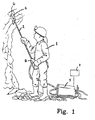
- Figure 1 shows a manual installation of rock bolts.
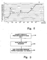
- Figure 2 shows schematically an expansion process for expanding a rock bolt.
- Figure 3 shows a flow chart illustrating the installation sequence in accordance with the present invention.
- With reference to figure 1 a manual installation of expandable rock bolts in accordance with the present invention will now be described. An operator 1 has access to an installation apparatus for setting of rock bolts comprising an installation arm 2, with a
handle 3 in one end and aninstallation chuck 4 in the other. The installation arm 2 is connected to a high-pressure pump 5, pumping out a pressure media, such as water, with a predetermined pressure into the rock bolt 6. By for example pressing thehandle 3, the operator 1 starts an installation sequence, which he then may not interrupt other than by pressing a reset button, which is preferably placed on the high-pressure pump 5. - Unlike the prior art, in which the operator himself has to decide if an installation of a rock bolt is completed and he himself has to evaluate how long a rock bolt has been allowed to expand, in accordance with the present invention the operator 1 only needs to start an installation sequence.
- With reference to figure 2, the expansion process of a rock bolt is now described briefly in order to clarify the installation sequence. During the phase marked 1 the rock bolt is filled with water (or other liquid), whereby the pressure need not be so high. Thereafter the pressure limit for permanent deformation is exceeded, marked by 2. When the permanent deformation occurs,
phase 3, the pressure drops somewhat, and the indentation of the rock bolt unfolds and is pressed, inphase 4, to abutment to the rock. Inphase 4 elastic strain of the rock also occurs. In the last phase, which is the critical phase for the installation, the pressure reaches the prescribed limit. The pressure should be maintained at this level for a predetermined period of time, typically 6 seconds, in order to allow complete expansion of the rock bolt in the bore hole. Different bolts require different pressures, and even in rock bolts of the same kind the resistance may vary somewhat. A pressure slightly above 300 bars is however usually enough. - The
control system 7 in accordance with the present invention has as main function to ensure that the cycle, described in figure 2, cannot be interrupted manually by the operator 1. The operator 1 should thus not be able to interrupt the installation by lettibg go of thehandle 3, and the installation sequence continues even if the operator 1 should release thehandle 3. - The
control system 7 is shown in figure 1 only schematically as a separate unit connected to a high-pressure pump 5, but it is realised that it may constitute a part of the high-pressure pump 5, or for example form part elsewhere in the pump system. Thecontrol system 7 comprises means, for example a timer, that when a prescribed time has elapsed, makes a relay switch off the high-pressure pump 5. The rock bolt should be pressurised with a predetermined pressure during the period of time indicated inphase 5, say 6 seconds, and thechuck 4 does not loosen its grip of the rock bolt 6 before this time has elapsed. If the pressure during this phase should sink below the indicated pressure the timer is reset and restarted when the indicated pressure has again been reached. - The installation comprises the following steps, illustrated by the flow chart of figure 3: in
step 100 the operator manually connects a pressure source to a rock bolt to be expanded; instep 102 the operator starts a sequence whereby the rock bolt is pressurised to a predetermined pressure; and instep 104 thecontrol system 7 ensures that the predetermined pressure is kept during a predetermined period of time, that cannot be affected by the operator. - For example, when the operator presses in the handle in an installation apparatus for rock bolts, a sensor in the handle may give off a signal to the
control system 7, whereby the installation sequence is started. The sensor is connected to acontrol system 7 controlling the high-pressure pump 5. Thecontrol system 7 then starts a time metering, for example by means of a timer, and controls that a set pressure is reached in the rock bolt during a certain, prescribed time (the time and the pressure corresponding tophase 5 in figure 2). When the prescribed time period has elapsed, a relay, that receives a signal from the timer when the prescribed time has elapsed, may switch off the pressure source, for example the high-pressure pump 5. The time metering need not be governed by a mechanical unit, but may of course alternatively be accomplished by software. When the prescribed time has elapsed, the operator knows that the installation is finished, and is then certain that the rock bolt has been installed correctly. - The three way valve described in the introduction may thus in the present invention be eliminated and be replaced with for example a sensor.
- Sometimes it happens that a rock bolt cannot be expanded, for example if there is no hole in the rock bolt. If that is the case, the pressure will reach the indicated value immediately and the sequence is interrupted after the predetermined period of time as usual. The rock bolt will then however not be expanded and there is no danger that a partly expanded rock bolt stays in the bore hole. Thereby the operator is aware of the fact that the rock bolt is defective and the quality of the rock support can thereby always be guaranteed.
- The
control system 7 also handles the situation that come up when the prescribed pressure in the rock bolt cannot be reached, as is the case for example when a rock bolt is leaking. The operator may then stop the high-pressure pump by pressing the reset button on the handle of the installation arm or on the high-pressure pump itself, or the like. Alternatively a function may be implemented where for example a timer controls that the sequence is performed within a prescribed maximum period of time, within which the prescribed pressure should have been reached and held during the prescribed time period. The timer is then set on a time period concerning the total installation time, and if this time period is exceeded the installation sequence is interrupted. It is important that the total installation time period set is not set to be too short, since the installation of the rock bolt then may be interrupted prematurely without the operator being aware of it. If thecontrol system 7 comprises such a maximum installation time, after which the installation sequence is interrupted, a certain signal may be given off in order to alert the operator that the maximum time has been exceeded. Moreover, an error message may be presented to the operator, for example "Installation failed". The operator must then restart (reset) the system. - The above function may be used when the pressure never reaches the prescribed and required level, but also if the pressure suddenly falls below this level before the required time has elapsed. The bolt is then not accurately installed, but has only expanded partly, and the
control system 7 should then warn the operator. Partly expanded bolts may for example occur in case a rock bolt starts to leak, or if there arises a leakage in the pump system. Since the operator, in accordance with the present invention, may only interrupt an installation manually by pressing a reset button, and since he otherwise will be presented with an error message or a signal, he will thus always be aware of the case that a rock bolt has not been installed correctly. - If an operator should start an installation sequence by mistake, for example if he starts the sequence without there being a rock bolt in the chuck, the
control system 7 senses this, in an alternative embodiment. Thecontrol system 7 controls that the increase of pressure is normal, which is not the case for example if there is no rock bolt. Thecontrol system 7 then interrupts the sequence and an immediate restart of the same is possible. In an alternative embodiment, the starting of the installation requires action of the operator during a certain determined period of time, for example that the operator presses the handle during a certain period of time, say 2 seconds, before the sequence is started and is so to say locked and can no longer be interrupted by the operator. During this starting phase, before the sequence itself starts, the operator has time to see for example if there is a leakage in the pump system, and may then prevent the start of the sequence. - In accordance with an embodiment of the invention, the
control system 7 may also include a counter registering the number of correctly installed bolts. This may for example be advantageous when it is critically important that a certain number of rock bolts have been installed or if statistics is desired. - In accordance with the invention, the expansion of a rock bolt cannot be interrupted prematurely by mistake, and thereby there is no risk for the anchorage of the rock bolt into the rock to be reduced and thereby to render the supporting of rock deficient.
- Moreover, by means of the present invention all uncertainty of the operator whether an expandable rock bolt has been installed correctly or not may be eliminated. In accordance with the invention an operator always knows if an installation has succeeded or not.
- The
control system 7 in accordance with the present invention ensures that the rock bolt 6 is-pressurised with a prescribed pressure and that the pressure is then held during a prescribed, required period of time. This provides a very reliable manual installation of rock bolts. - The invention provides the possibility to store pressure and time for individual bolts for later quality follow-up.
Claims (16)
- A method for manual installation by pressurisation of expandable rock bolts, including manual connection of a pressure source to a rock bolt to be expanded characterised in that the method comprises the steps ofan operator starting a sequence whereby the rock bolt is pressurised to a predetermined pressure, andensuring by means of said sequence , and by an apparatus comprising a control system comprising means for ensuring that said pressure is held during a predetermined period of time, that the predetermined pressure is kept for a predetermined period of time.
- Method as claimed in claim 1, wherein a signal is given off when the sequence is successfully performed.
- Method as claimed in claim 1 or 2, wherein a signal is given off when the sequence has not been successfully performed.
- Method as claimed in any of claims 1-3, wherein an error message is given off when the sequence has not been successfully performed.
- Method as claimed in any of claims 1-4, wherein a timer is cleared if the redetermined pressure during the predetermined period of time falls bellow a prescribed pressure level, and is further restarted when the prescribed pressure level is reached again.
- Method as claimed in any of the preceding claims, wherein a chuck used for installation does not release its grip of a rock bolt before the predetermined period of time has elapsed.
- Method as claimed in any of the preceding claims, wherein the starting of the installation requires action from an operator during a certain determined period of time before the sequence is started.
- A control systs or connection to a pressure source for manual installation by pressurisation of expandable rock bolts, characterised in that the control system (7) comprisesmeans for ensuring that a rock bolt is pressurised to a predetermined pressure, andmeans for ensuring that said pressure is held during a predetermined period of time.
- Control system as claimed in claim 8, wherein said means for ensuring a pressure comprises a timer arranged to determine the duration of the predetermined pressure.
- Control system as claimed in claim 9, wherein the timer is arranged to be cleared if the desired pressure during a predetermined period of time falls below a given pressure level, and further arranged to be restarted when the given pressure level is again reached.
- Control system as claimed in any of claims 8-10, wherein the control system (7) comprises a reset button for enabling interruption of the installation.
- Control system as claimed in any of claims 8-11, wherein the control system (7) comprises a counter counting the number of correctly installed rock bolts.
- Control system as claimed in any of claims 8-12, wherein the control system (7) comprises means arranged to give off a signal when the installation has succeeded.
- Control system as claimed in any of claims 8-13, wherein the control system (7) comprises means arranged to give off a signal when the installation has not succeeded.
- Control system as claimed in any of claims 8-14, wherein an error message is given when the sequence has not been performed successfully.
- An apparatus for installing a rock bolt expandable by pressurization, the apparatus comprising a pressure source and means for manual coupling to an expandable rock bolt characterized in that the apparatus comprises a.control system (7) as claimed in any of claims 8-15.
Priority Applications (2)
| Application Number | Priority Date | Filing Date | Title |
|---|---|---|---|
| PL04732534T PL1623094T3 (en) | 2003-05-12 | 2004-05-12 | Controlled expansion of rock bolt |
| SI200430646T SI1623094T1 (en) | 2003-05-12 | 2004-05-12 | Controlled expansion of rock bolt |
Applications Claiming Priority (2)
| Application Number | Priority Date | Filing Date | Title |
|---|---|---|---|
| SE0301377A SE525179C2 (en) | 2003-05-12 | 2003-05-12 | Method and control system for pressure expandable rock bolts |
| PCT/SE2004/000733 WO2004099570A1 (en) | 2003-05-12 | 2004-05-12 | Controlled expansion of rock bolt |
Publications (2)
| Publication Number | Publication Date |
|---|---|
| EP1623094A1 EP1623094A1 (en) | 2006-02-08 |
| EP1623094B1 true EP1623094B1 (en) | 2008-01-09 |
Family
ID=20291275
Family Applications (1)
| Application Number | Title | Priority Date | Filing Date |
|---|---|---|---|
| EP04732534A Expired - Lifetime EP1623094B1 (en) | 2003-05-12 | 2004-05-12 | Controlled expansion of rock bolt |
Country Status (22)
| Country | Link |
|---|---|
| US (1) | US7320560B2 (en) |
| EP (1) | EP1623094B1 (en) |
| JP (1) | JP2006526093A (en) |
| KR (1) | KR20060012603A (en) |
| CN (1) | CN1791734B (en) |
| AT (1) | ATE383497T1 (en) |
| AU (1) | AU2004236623B2 (en) |
| BR (1) | BRPI0410167B1 (en) |
| CA (1) | CA2525458C (en) |
| DE (1) | DE602004011207T2 (en) |
| DK (1) | DK1623094T3 (en) |
| ES (1) | ES2297419T3 (en) |
| HR (1) | HRP20080031T3 (en) |
| IL (1) | IL171669A (en) |
| NO (1) | NO336673B1 (en) |
| PL (1) | PL1623094T3 (en) |
| PT (1) | PT1623094E (en) |
| RU (1) | RU2338067C2 (en) |
| SE (1) | SE525179C2 (en) |
| SI (1) | SI1623094T1 (en) |
| WO (1) | WO2004099570A1 (en) |
| ZA (1) | ZA200508477B (en) |
Families Citing this family (5)
| Publication number | Priority date | Publication date | Assignee | Title |
|---|---|---|---|---|
| SE528911C2 (en) * | 2005-01-19 | 2007-03-13 | Atlas Copco Rock Drills Ab | Procedure and system for monitoring and documenting installation of rock reinforcement bolt |
| SE531009C2 (en) * | 2005-05-03 | 2008-11-18 | Atlas Copco Rock Drills Ab | Device and method for installing a rock bolt and a rock bolt installation rig |
| KR101358946B1 (en) * | 2012-12-05 | 2014-02-07 | 코오롱글로벌 주식회사 | Joining device for rock bolt and operating method thereof |
| CZ2016244A3 (en) | 2016-04-28 | 2017-06-28 | Dsi Underground Ip Holdings Luxembourg Sarl | An expandable rock bolt with a clamping indicator |
| KR101696374B1 (en) | 2016-04-28 | 2017-01-13 | 주식회사 에이치아이씨 | Method for installing checkable the installation status of expanding type rock bolt |
Family Cites Families (13)
| Publication number | Priority date | Publication date | Assignee | Title |
|---|---|---|---|---|
| SE427764B (en) * | 1979-03-09 | 1983-05-02 | Atlas Copco Ab | MOUNTAIN CULTURAL PROCEDURES REALLY RUCH MOUNTED MOUNTAIN |
| NO159201C (en) * | 1980-09-08 | 1988-12-07 | Atlas Copco Ab | PROCEDURE FOR BOLTING IN MOUNTAIN AND COMBINED EXPANSION BOLT AND INSTALLATION DEVICE FOR SAME. |
| US4954017A (en) * | 1980-11-10 | 1990-09-04 | The Curators Of The University Of Missouri | Expansion bolt and mine roof reinforcement |
| SE8106165L (en) * | 1981-10-19 | 1983-04-20 | Atlas Copco Ab | PROCEDURE FOR MOUNTAIN AND MOUNTAIN |
| SE457894B (en) * | 1985-06-17 | 1989-02-06 | Atlas Copco Ab | MAKE STABILIZING MOUNTAINS |
| SE8605408D0 (en) | 1986-12-16 | 1986-12-16 | Atlas Copco Ab | METHOD OF STABILIZING A ROCK STRUCTURE AND STABILIZING THEREFOR |
| SU1737130A1 (en) * | 1990-06-21 | 1992-05-30 | Институт Горного Дела Ан Казсср | Anchor |
| CN1073501A (en) * | 1991-12-19 | 1993-06-23 | 新汶矿务局 | Hydraulic expansion type anchor stock is prevented the roof fall of coal face wall caving |
| RU2072048C1 (en) * | 1992-12-29 | 1997-01-20 | Сергей Алексеевич Логашкин | Anchor |
| SE502795C2 (en) * | 1994-06-02 | 1996-01-15 | Atlas Copco Rock Drills Ab | Tubular rock bolt with orientation means |
| SE9600640L (en) * | 1996-02-21 | 1997-03-17 | Atlas Copco Rock Drills Ab | Splice of a tubular rock bolt |
| JPH10140998A (en) * | 1996-11-13 | 1998-05-26 | Fujita Corp | Ground stabilization method |
| JP3630516B2 (en) * | 1997-01-27 | 2005-03-16 | 日立建機株式会社 | Automatic driving excavator |
-
2003
- 2003-05-12 SE SE0301377A patent/SE525179C2/en not_active IP Right Cessation
-
2004
- 2004-05-12 ZA ZA200508477A patent/ZA200508477B/en unknown
- 2004-05-12 KR KR1020057021527A patent/KR20060012603A/en not_active Ceased
- 2004-05-12 ES ES04732534T patent/ES2297419T3/en not_active Expired - Lifetime
- 2004-05-12 AT AT04732534T patent/ATE383497T1/en active
- 2004-05-12 RU RU2005138521/03A patent/RU2338067C2/en active
- 2004-05-12 BR BRPI0410167A patent/BRPI0410167B1/en not_active IP Right Cessation
- 2004-05-12 PL PL04732534T patent/PL1623094T3/en unknown
- 2004-05-12 DE DE602004011207T patent/DE602004011207T2/en not_active Expired - Lifetime
- 2004-05-12 CA CA2525458A patent/CA2525458C/en not_active Expired - Fee Related
- 2004-05-12 EP EP04732534A patent/EP1623094B1/en not_active Expired - Lifetime
- 2004-05-12 WO PCT/SE2004/000733 patent/WO2004099570A1/en not_active Ceased
- 2004-05-12 US US10/555,026 patent/US7320560B2/en not_active Expired - Lifetime
- 2004-05-12 SI SI200430646T patent/SI1623094T1/en unknown
- 2004-05-12 JP JP2006508055A patent/JP2006526093A/en active Pending
- 2004-05-12 DK DK04732534T patent/DK1623094T3/en active
- 2004-05-12 CN CN2004800128692A patent/CN1791734B/en not_active Expired - Fee Related
- 2004-05-12 PT PT04732534T patent/PT1623094E/en unknown
- 2004-05-12 AU AU2004236623A patent/AU2004236623B2/en not_active Ceased
- 2004-05-12 HR HR20080031T patent/HRP20080031T3/en unknown
-
2005
- 2005-10-30 IL IL171669A patent/IL171669A/en not_active IP Right Cessation
- 2005-12-09 NO NO20055862A patent/NO336673B1/en not_active IP Right Cessation
Also Published As
| Publication number | Publication date |
|---|---|
| SI1623094T1 (en) | 2008-06-30 |
| PT1623094E (en) | 2008-01-29 |
| DE602004011207T2 (en) | 2008-12-24 |
| DE602004011207D1 (en) | 2008-02-21 |
| RU2338067C2 (en) | 2008-11-10 |
| CA2525458C (en) | 2012-11-27 |
| WO2004099570A1 (en) | 2004-11-18 |
| CN1791734A (en) | 2006-06-21 |
| CA2525458A1 (en) | 2004-11-18 |
| IL171669A (en) | 2010-02-17 |
| HRP20080031T3 (en) | 2008-02-29 |
| ATE383497T1 (en) | 2008-01-15 |
| NO336673B1 (en) | 2015-10-19 |
| RU2005138521A (en) | 2006-06-10 |
| WO2004099570A8 (en) | 2005-12-08 |
| EP1623094A1 (en) | 2006-02-08 |
| AU2004236623A1 (en) | 2004-11-18 |
| PL1623094T3 (en) | 2008-05-30 |
| ZA200508477B (en) | 2007-05-30 |
| AU2004236623B2 (en) | 2008-12-18 |
| ES2297419T3 (en) | 2008-05-01 |
| KR20060012603A (en) | 2006-02-08 |
| SE0301377D0 (en) | 2003-05-12 |
| SE0301377L (en) | 2004-11-13 |
| BRPI0410167A (en) | 2006-05-16 |
| DK1623094T3 (en) | 2008-04-28 |
| JP2006526093A (en) | 2006-11-16 |
| SE525179C2 (en) | 2004-12-21 |
| NO20055862L (en) | 2006-02-03 |
| CN1791734B (en) | 2012-10-10 |
| US7320560B2 (en) | 2008-01-22 |
| US20070036614A1 (en) | 2007-02-15 |
| BRPI0410167B1 (en) | 2016-08-16 |
Similar Documents
| Publication | Publication Date | Title |
|---|---|---|
| CA2525458C (en) | Controlled expansion of rock bolt | |
| JPH07225686A (en) | Program down-loading system | |
| EP4308016B1 (en) | Automatic tourniquet apparatus having patient hazard shield | |
| JPS6233155B2 (en) | ||
| JPH06136967A (en) | Device for differential settlement of structures | |
| JP3056205B1 (en) | Water-based automatic fire extinguishing equipment | |
| JP2020085368A (en) | Heat pump water heater | |
| KR101696374B1 (en) | Method for installing checkable the installation status of expanding type rock bolt | |
| KR100411560B1 (en) | The method for detecting communication disturbance of the room temperature controling system for boilers | |
| JP2001107875A (en) | Water supply system | |
| KR200416714Y1 (en) | Automatic pressure regulator of pressure bath using contact pressure gauge | |
| JP3261979B2 (en) | Bubble tub pump control method | |
| JPH0370985B2 (en) | ||
| JP3205034B2 (en) | Bathtub equipment | |
| JP2780839B2 (en) | Initial injection method of circulating water in hot water heating system | |
| JP3570906B2 (en) | Control device for submersible pump | |
| CN121539207A (en) | A full-bore floating lower casing device | |
| JP2615537B2 (en) | Torcon oil changer | |
| JPH06149557A (en) | Firmware automatic recovery method | |
| JP2009187051A (en) | Information processing apparatus manufacturing method and power connection disconnection apparatus | |
| JPH0882404A (en) | Detecting method for choking of water level control cylinder during starting of boiler | |
| JPH05317449A (en) | Automatic inspection equipment for fire extinguishing equipment | |
| JP2001221673A (en) | Fuel tank liquid level monitoring system | |
| JPH03132000A (en) | vending machine ice making device | |
| JPH0370984B2 (en) |
Legal Events
| Date | Code | Title | Description |
|---|---|---|---|
| PUAI | Public reference made under article 153(3) epc to a published international application that has entered the european phase |
Free format text: ORIGINAL CODE: 0009012 |
|
| 17P | Request for examination filed |
Effective date: 20051119 |
|
| AK | Designated contracting states |
Kind code of ref document: A1 Designated state(s): AT BE BG CH CY CZ DE DK EE ES FI FR GB GR HU IE IT LI LU MC NL PL PT RO SE SI SK TR |
|
| AX | Request for extension of the european patent |
Extension state: HR LV |
|
| RAX | Requested extension states of the european patent have changed |
Extension state: HR Payment date: 20051119 Extension state: LV Payment date: 20051119 |
|
| 17Q | First examination report despatched |
Effective date: 20061227 |
|
| RIN1 | Information on inventor provided before grant (corrected) |
Inventor name: PERSSON, TOMMY Inventor name: OERJAS, NICLAS Inventor name: KANFLOD, MORGAN Inventor name: SJOESTEDT, GOERAN Inventor name: TOIVONEN, TAPIO Inventor name: GUSTAVSSON, HANS Inventor name: OEBERG, FREDRIK |
|
| RIN1 | Information on inventor provided before grant (corrected) |
Inventor name: OERJAS, NICLAS Inventor name: PERSSON, TOMMY Inventor name: GUSTAVSSON, HANS Inventor name: SJOESTEDT, GOERAN Inventor name: TOIVONEN, TAPIO Inventor name: OEBERG, FREDRIK Inventor name: KANFLOD, MORGAN |
|
| GRAP | Despatch of communication of intention to grant a patent |
Free format text: ORIGINAL CODE: EPIDOSNIGR1 |
|
| GRAS | Grant fee paid |
Free format text: ORIGINAL CODE: EPIDOSNIGR3 |
|
| GRAA | (expected) grant |
Free format text: ORIGINAL CODE: 0009210 |
|
| AK | Designated contracting states |
Kind code of ref document: B1 Designated state(s): AT BE BG CH CY CZ DE DK EE ES FI FR GB GR HU IE IT LI LU MC NL PL PT RO SE SI SK TR |
|
| AX | Request for extension of the european patent |
Extension state: HR LV |
|
| REG | Reference to a national code |
Ref country code: GB Ref legal event code: FG4D |
|
| REG | Reference to a national code |
Ref country code: HR Ref legal event code: TUEP Ref document number: P20080031 Country of ref document: HR |
|
| REG | Reference to a national code |
Ref country code: PT Ref legal event code: SC4A Free format text: AVAILABILITY OF NATIONAL TRANSLATION Effective date: 20080116 |
|
| REG | Reference to a national code |
Ref country code: CH Ref legal event code: NV Representative=s name: BRAUNPAT BRAUN EDER AG Ref country code: CH Ref legal event code: EP |
|
| REG | Reference to a national code |
Ref country code: IE Ref legal event code: FG4D |
|
| REG | Reference to a national code |
Ref country code: RO Ref legal event code: EPE |
|
| REF | Corresponds to: |
Ref document number: 602004011207 Country of ref document: DE Date of ref document: 20080221 Kind code of ref document: P |
|
| REG | Reference to a national code |
Ref country code: HR Ref legal event code: T1PR Ref document number: P20080031 Country of ref document: HR |
|
| REG | Reference to a national code |
Ref country code: GR Ref legal event code: EP Ref document number: 20080400511 Country of ref document: GR |
|
| REG | Reference to a national code |
Ref country code: DK Ref legal event code: T3 |
|
| REG | Reference to a national code |
Ref country code: ES Ref legal event code: FG2A Ref document number: 2297419 Country of ref document: ES Kind code of ref document: T3 |
|
| REG | Reference to a national code |
Ref country code: PL Ref legal event code: T3 |
|
| PG25 | Lapsed in a contracting state [announced via postgrant information from national office to epo] |
Ref country code: SE Free format text: LAPSE BECAUSE OF FAILURE TO SUBMIT A TRANSLATION OF THE DESCRIPTION OR TO PAY THE FEE WITHIN THE PRESCRIBED TIME-LIMIT Effective date: 20080409 |
|
| PLBE | No opposition filed within time limit |
Free format text: ORIGINAL CODE: 0009261 |
|
| STAA | Information on the status of an ep patent application or granted ep patent |
Free format text: STATUS: NO OPPOSITION FILED WITHIN TIME LIMIT |
|
| REG | Reference to a national code |
Ref country code: EE Ref legal event code: HC1A Ref document number: E002032 Country of ref document: EE |
|
| 26N | No opposition filed |
Effective date: 20081010 |
|
| PG25 | Lapsed in a contracting state [announced via postgrant information from national office to epo] |
Ref country code: MC Free format text: LAPSE BECAUSE OF NON-PAYMENT OF DUE FEES Effective date: 20080531 |
|
| REG | Reference to a national code |
Ref country code: HU Ref legal event code: AG4A Ref document number: E005070 Country of ref document: HU |
|
| PG25 | Lapsed in a contracting state [announced via postgrant information from national office to epo] |
Ref country code: CY Free format text: LAPSE BECAUSE OF FAILURE TO SUBMIT A TRANSLATION OF THE DESCRIPTION OR TO PAY THE FEE WITHIN THE PRESCRIBED TIME-LIMIT Effective date: 20080109 |
|
| REG | Reference to a national code |
Ref country code: HR Ref legal event code: ODRP Ref document number: P20080031 Country of ref document: HR Payment date: 20120404 Year of fee payment: 9 |
|
| PGFP | Annual fee paid to national office [announced via postgrant information from national office to epo] |
Ref country code: CZ Payment date: 20120425 Year of fee payment: 9 Ref country code: SK Payment date: 20120424 Year of fee payment: 9 Ref country code: TR Payment date: 20120413 Year of fee payment: 9 Ref country code: EE Payment date: 20120416 Year of fee payment: 9 Ref country code: HU Payment date: 20120424 Year of fee payment: 9 Ref country code: BG Payment date: 20120405 Year of fee payment: 9 Ref country code: LU Payment date: 20120511 Year of fee payment: 9 Ref country code: IE Payment date: 20120510 Year of fee payment: 9 Ref country code: NL Payment date: 20120515 Year of fee payment: 9 Ref country code: DK Payment date: 20120510 Year of fee payment: 9 |
|
| PGFP | Annual fee paid to national office [announced via postgrant information from national office to epo] |
Ref country code: RO Payment date: 20120413 Year of fee payment: 9 Ref country code: GR Payment date: 20120417 Year of fee payment: 9 |
|
| PGFP | Annual fee paid to national office [announced via postgrant information from national office to epo] |
Ref country code: SI Payment date: 20120412 Year of fee payment: 9 |
|
| REG | Reference to a national code |
Ref country code: HR Ref legal event code: PBON Ref document number: P20080031 Country of ref document: HR Effective date: 20130513 |
|
| REG | Reference to a national code |
Ref country code: NL Ref legal event code: V1 Effective date: 20131201 |
|
| PG25 | Lapsed in a contracting state [announced via postgrant information from national office to epo] |
Ref country code: CZ Free format text: LAPSE BECAUSE OF NON-PAYMENT OF DUE FEES Effective date: 20130512 Ref country code: SK Free format text: LAPSE BECAUSE OF NON-PAYMENT OF DUE FEES Effective date: 20130512 Ref country code: EE Free format text: LAPSE BECAUSE OF NON-PAYMENT OF DUE FEES Effective date: 20130531 |
|
| REG | Reference to a national code |
Ref country code: SK Ref legal event code: MM4A Ref document number: E 3197 Country of ref document: SK Effective date: 20130512 |
|
| REG | Reference to a national code |
Ref country code: GR Ref legal event code: ML Ref document number: 20080400511 Country of ref document: GR Effective date: 20131204 |
|
| REG | Reference to a national code |
Ref country code: DK Ref legal event code: EBP Effective date: 20130531 |
|
| REG | Reference to a national code |
Ref country code: EE Ref legal event code: MM4A Ref document number: E002032 Country of ref document: EE Effective date: 20130531 |
|
| REG | Reference to a national code |
Ref country code: IE Ref legal event code: MM4A |
|
| PG25 | Lapsed in a contracting state [announced via postgrant information from national office to epo] |
Ref country code: RO Free format text: LAPSE BECAUSE OF NON-PAYMENT OF DUE FEES Effective date: 20130512 Ref country code: NL Free format text: LAPSE BECAUSE OF NON-PAYMENT OF DUE FEES Effective date: 20131201 Ref country code: HU Free format text: LAPSE BECAUSE OF NON-PAYMENT OF DUE FEES Effective date: 20130513 Ref country code: SI Free format text: LAPSE BECAUSE OF NON-PAYMENT OF DUE FEES Effective date: 20130513 Ref country code: GR Free format text: LAPSE BECAUSE OF NON-PAYMENT OF DUE FEES Effective date: 20131204 |
|
| REG | Reference to a national code |
Ref country code: SI Ref legal event code: KO00 Effective date: 20140110 |
|
| PG25 | Lapsed in a contracting state [announced via postgrant information from national office to epo] |
Ref country code: IE Free format text: LAPSE BECAUSE OF NON-PAYMENT OF DUE FEES Effective date: 20130512 Ref country code: DK Free format text: LAPSE BECAUSE OF NON-PAYMENT OF DUE FEES Effective date: 20130531 |
|
| PG25 | Lapsed in a contracting state [announced via postgrant information from national office to epo] |
Ref country code: BG Free format text: LAPSE BECAUSE OF NON-PAYMENT OF DUE FEES Effective date: 20140630 |
|
| PG25 | Lapsed in a contracting state [announced via postgrant information from national office to epo] |
Ref country code: BG Free format text: LAPSE BECAUSE OF NON-PAYMENT OF DUE FEES Effective date: 20130531 |
|
| PG25 | Lapsed in a contracting state [announced via postgrant information from national office to epo] |
Ref country code: LU Free format text: LAPSE BECAUSE OF NON-PAYMENT OF DUE FEES Effective date: 20130512 |
|
| PG25 | Lapsed in a contracting state [announced via postgrant information from national office to epo] |
Ref country code: TR Free format text: LAPSE BECAUSE OF NON-PAYMENT OF DUE FEES Effective date: 20130512 |
|
| REG | Reference to a national code |
Ref country code: DE Ref legal event code: R082 Ref document number: 602004011207 Country of ref document: DE Representative=s name: PATENTANWAELTE OLBRICHT, BUCHHOLD, KEULERTZ PA, DE |
|
| REG | Reference to a national code |
Ref country code: FR Ref legal event code: PLFP Year of fee payment: 13 |
|
| REG | Reference to a national code |
Ref country code: FR Ref legal event code: PLFP Year of fee payment: 14 |
|
| REG | Reference to a national code |
Ref country code: BE Ref legal event code: HC Owner name: EPIROC ROCK DRILLS AKTIEBOLAG; SE Free format text: DETAILS ASSIGNMENT: CHANGE OF OWNER(S), CHANGEMENT DE NOM DU PROPRIETAIRE; FORMER OWNER NAME: ATLAS COPCO ROCK DRILLS AB Effective date: 20180215 |
|
| REG | Reference to a national code |
Ref country code: ES Ref legal event code: PC2A Owner name: EPIROC ROCK DRILLS AKTIEBOLAG Effective date: 20180319 |
|
| REG | Reference to a national code |
Ref country code: CH Ref legal event code: PFA Owner name: EPIROC ROCK DRILLS AKTIEBOLAG, SE Free format text: FORMER OWNER: ATLAS COPCO ROCK DRILLS AB, SE |
|
| REG | Reference to a national code |
Ref country code: AT Ref legal event code: HC Ref document number: 383497 Country of ref document: AT Kind code of ref document: T Owner name: EPIROC ROCK DRILLS AKTIEBOLAG, SE Effective date: 20180326 |
|
| REG | Reference to a national code |
Ref country code: FR Ref legal event code: PLFP Year of fee payment: 15 |
|
| REG | Reference to a national code |
Ref country code: DE Ref legal event code: R082 Ref document number: 602004011207 Country of ref document: DE Representative=s name: PATENTANWAELTE OLBRICHT, BUCHHOLD, KEULERTZ PA, DE Ref country code: DE Ref legal event code: R081 Ref document number: 602004011207 Country of ref document: DE Owner name: EPIROC ROCK DRILLS AKTIEBOLAG, SE Free format text: FORMER OWNER: ATLAS COPCO ROCK DRILLS AB, OEREBRO, SE |
|
| REG | Reference to a national code |
Ref country code: FR Ref legal event code: CD Owner name: EPIROC ROCK DRILLS AKTIEBOLAG, SE Effective date: 20181107 |
|
| PGFP | Annual fee paid to national office [announced via postgrant information from national office to epo] |
Ref country code: DE Payment date: 20200528 Year of fee payment: 17 Ref country code: CH Payment date: 20200603 Year of fee payment: 17 |
|
| PGFP | Annual fee paid to national office [announced via postgrant information from national office to epo] |
Ref country code: GB Payment date: 20200527 Year of fee payment: 17 Ref country code: BE Payment date: 20200527 Year of fee payment: 17 Ref country code: PL Payment date: 20200421 Year of fee payment: 17 |
|
| PGFP | Annual fee paid to national office [announced via postgrant information from national office to epo] |
Ref country code: AT Payment date: 20200421 Year of fee payment: 17 |
|
| PGFP | Annual fee paid to national office [announced via postgrant information from national office to epo] |
Ref country code: FR Payment date: 20210525 Year of fee payment: 18 Ref country code: FI Payment date: 20210527 Year of fee payment: 18 Ref country code: IT Payment date: 20210524 Year of fee payment: 18 Ref country code: PT Payment date: 20210427 Year of fee payment: 18 |
|
| PGFP | Annual fee paid to national office [announced via postgrant information from national office to epo] |
Ref country code: ES Payment date: 20210601 Year of fee payment: 18 |
|
| REG | Reference to a national code |
Ref country code: DE Ref legal event code: R119 Ref document number: 602004011207 Country of ref document: DE |
|
| REG | Reference to a national code |
Ref country code: CH Ref legal event code: PL |
|
| REG | Reference to a national code |
Ref country code: AT Ref legal event code: MM01 Ref document number: 383497 Country of ref document: AT Kind code of ref document: T Effective date: 20210512 |
|
| GBPC | Gb: european patent ceased through non-payment of renewal fee |
Effective date: 20210512 |
|
| PG25 | Lapsed in a contracting state [announced via postgrant information from national office to epo] |
Ref country code: LI Free format text: LAPSE BECAUSE OF NON-PAYMENT OF DUE FEES Effective date: 20210531 Ref country code: AT Free format text: LAPSE BECAUSE OF NON-PAYMENT OF DUE FEES Effective date: 20210512 Ref country code: CH Free format text: LAPSE BECAUSE OF NON-PAYMENT OF DUE FEES Effective date: 20210531 |
|
| REG | Reference to a national code |
Ref country code: BE Ref legal event code: MM Effective date: 20210531 |
|
| PG25 | Lapsed in a contracting state [announced via postgrant information from national office to epo] |
Ref country code: GB Free format text: LAPSE BECAUSE OF NON-PAYMENT OF DUE FEES Effective date: 20210512 Ref country code: DE Free format text: LAPSE BECAUSE OF NON-PAYMENT OF DUE FEES Effective date: 20211201 |
|
| PG25 | Lapsed in a contracting state [announced via postgrant information from national office to epo] |
Ref country code: BE Free format text: LAPSE BECAUSE OF NON-PAYMENT OF DUE FEES Effective date: 20210531 |
|
| PG25 | Lapsed in a contracting state [announced via postgrant information from national office to epo] |
Ref country code: PT Free format text: LAPSE BECAUSE OF NON-PAYMENT OF DUE FEES Effective date: 20221114 Ref country code: FI Free format text: LAPSE BECAUSE OF NON-PAYMENT OF DUE FEES Effective date: 20220512 |
|
| PG25 | Lapsed in a contracting state [announced via postgrant information from national office to epo] |
Ref country code: FR Free format text: LAPSE BECAUSE OF NON-PAYMENT OF DUE FEES Effective date: 20220531 |
|
| REG | Reference to a national code |
Ref country code: ES Ref legal event code: FD2A Effective date: 20230629 |
|
| PG25 | Lapsed in a contracting state [announced via postgrant information from national office to epo] |
Ref country code: IT Free format text: LAPSE BECAUSE OF NON-PAYMENT OF DUE FEES Effective date: 20220512 Ref country code: ES Free format text: LAPSE BECAUSE OF NON-PAYMENT OF DUE FEES Effective date: 20220513 |
|
| PG25 | Lapsed in a contracting state [announced via postgrant information from national office to epo] |
Ref country code: PL Free format text: LAPSE BECAUSE OF NON-PAYMENT OF DUE FEES Effective date: 20210512 |