EP1622559B1 - Patient chair with a vertically movable seat - Google Patents
Patient chair with a vertically movable seat Download PDFInfo
- Publication number
- EP1622559B1 EP1622559B1 EP04731107A EP04731107A EP1622559B1 EP 1622559 B1 EP1622559 B1 EP 1622559B1 EP 04731107 A EP04731107 A EP 04731107A EP 04731107 A EP04731107 A EP 04731107A EP 1622559 B1 EP1622559 B1 EP 1622559B1
- Authority
- EP
- European Patent Office
- Prior art keywords
- patient
- chair
- patient chair
- seating device
- stand
- Prior art date
- Legal status (The legal status is an assumption and is not a legal conclusion. Google has not performed a legal analysis and makes no representation as to the accuracy of the status listed.)
- Expired - Lifetime
Links
Images

Classifications
-
- A—HUMAN NECESSITIES
- A61—MEDICAL OR VETERINARY SCIENCE; HYGIENE
- A61G—TRANSPORT, PERSONAL CONVEYANCES OR ACCOMMODATION SPECIALLY ADAPTED FOR PATIENTS OR DISABLED PERSONS; OPERATING TABLES OR CHAIRS; CHAIRS FOR DENTISTRY; FUNERAL DEVICES
- A61G5/00—Chairs or personal conveyances specially adapted for patients or disabled persons, e.g. wheelchairs
- A61G5/10—Parts, details or accessories
- A61G5/1056—Arrangements for adjusting the seat
- A61G5/1059—Arrangements for adjusting the seat adjusting the height of the seat
-
- A—HUMAN NECESSITIES
- A61—MEDICAL OR VETERINARY SCIENCE; HYGIENE
- A61G—TRANSPORT, PERSONAL CONVEYANCES OR ACCOMMODATION SPECIALLY ADAPTED FOR PATIENTS OR DISABLED PERSONS; OPERATING TABLES OR CHAIRS; CHAIRS FOR DENTISTRY; FUNERAL DEVICES
- A61G5/00—Chairs or personal conveyances specially adapted for patients or disabled persons, e.g. wheelchairs
- A61G5/10—Parts, details or accessories
- A61G5/1056—Arrangements for adjusting the seat
- A61G5/1075—Arrangements for adjusting the seat tilting the whole seat backwards
-
- A—HUMAN NECESSITIES
- A61—MEDICAL OR VETERINARY SCIENCE; HYGIENE
- A61G—TRANSPORT, PERSONAL CONVEYANCES OR ACCOMMODATION SPECIALLY ADAPTED FOR PATIENTS OR DISABLED PERSONS; OPERATING TABLES OR CHAIRS; CHAIRS FOR DENTISTRY; FUNERAL DEVICES
- A61G5/00—Chairs or personal conveyances specially adapted for patients or disabled persons, e.g. wheelchairs
- A61G5/10—Parts, details or accessories
- A61G5/12—Rests specially adapted therefor, e.g. for the head or the feet
- A61G5/125—Rests specially adapted therefor, e.g. for the head or the feet for arms
-
- A—HUMAN NECESSITIES
- A61—MEDICAL OR VETERINARY SCIENCE; HYGIENE
- A61G—TRANSPORT, PERSONAL CONVEYANCES OR ACCOMMODATION SPECIALLY ADAPTED FOR PATIENTS OR DISABLED PERSONS; OPERATING TABLES OR CHAIRS; CHAIRS FOR DENTISTRY; FUNERAL DEVICES
- A61G5/00—Chairs or personal conveyances specially adapted for patients or disabled persons, e.g. wheelchairs
- A61G5/10—Parts, details or accessories
- A61G5/12—Rests specially adapted therefor, e.g. for the head or the feet
- A61G5/127—Rests specially adapted therefor, e.g. for the head or the feet for lower legs
-
- A—HUMAN NECESSITIES
- A61—MEDICAL OR VETERINARY SCIENCE; HYGIENE
- A61G—TRANSPORT, PERSONAL CONVEYANCES OR ACCOMMODATION SPECIALLY ADAPTED FOR PATIENTS OR DISABLED PERSONS; OPERATING TABLES OR CHAIRS; CHAIRS FOR DENTISTRY; FUNERAL DEVICES
- A61G5/00—Chairs or personal conveyances specially adapted for patients or disabled persons, e.g. wheelchairs
- A61G5/10—Parts, details or accessories
- A61G5/12—Rests specially adapted therefor, e.g. for the head or the feet
- A61G5/128—Rests specially adapted therefor, e.g. for the head or the feet for feet
-
- A—HUMAN NECESSITIES
- A61—MEDICAL OR VETERINARY SCIENCE; HYGIENE
- A61G—TRANSPORT, PERSONAL CONVEYANCES OR ACCOMMODATION SPECIALLY ADAPTED FOR PATIENTS OR DISABLED PERSONS; OPERATING TABLES OR CHAIRS; CHAIRS FOR DENTISTRY; FUNERAL DEVICES
- A61G5/00—Chairs or personal conveyances specially adapted for patients or disabled persons, e.g. wheelchairs
- A61G5/10—Parts, details or accessories
- A61G5/14—Standing-up or sitting-down aids
-
- A—HUMAN NECESSITIES
- A61—MEDICAL OR VETERINARY SCIENCE; HYGIENE
- A61G—TRANSPORT, PERSONAL CONVEYANCES OR ACCOMMODATION SPECIALLY ADAPTED FOR PATIENTS OR DISABLED PERSONS; OPERATING TABLES OR CHAIRS; CHAIRS FOR DENTISTRY; FUNERAL DEVICES
- A61G5/00—Chairs or personal conveyances specially adapted for patients or disabled persons, e.g. wheelchairs
- A61G5/10—Parts, details or accessories
- A61G5/1002—Parts, details or accessories with toilet facilities
-
- Y—GENERAL TAGGING OF NEW TECHNOLOGICAL DEVELOPMENTS; GENERAL TAGGING OF CROSS-SECTIONAL TECHNOLOGIES SPANNING OVER SEVERAL SECTIONS OF THE IPC; TECHNICAL SUBJECTS COVERED BY FORMER USPC CROSS-REFERENCE ART COLLECTIONS [XRACs] AND DIGESTS
- Y10—TECHNICAL SUBJECTS COVERED BY FORMER USPC
- Y10S—TECHNICAL SUBJECTS COVERED BY FORMER USPC CROSS-REFERENCE ART COLLECTIONS [XRACs] AND DIGESTS
- Y10S297/00—Chairs and seats
- Y10S297/10—Occupant-arising assist
Definitions
- the invention relates to a patient chair with a vertically movable seat according to the preamble to claim 1.
- patient chairs In nursing and home care, patient chairs are used, whose seat and, in many cases, back are movable as a unit between upper and lower positions.
- the movability is desirable and frequently a requirement made by carers in order to be able in a fairly comfortable way, without straining their back, to move the patient between the patient chair and, for instance, a bed or a toilet.
- patient chairs which more or less satisfy this requirement are available on the market and described in the patent literature.
- patient chairs are known, which only allow said movement in a completely vertical direction.
- the drawback of these patient chairs is that it is difficult for the carer to take off/put on the patient's trousers, skirt, pants, napkin etc. or take sanitary measures as regards the patient's genitals if the patient is sitting on the patient chair.
- Other prior-art patient chairs allow backward inclination of the seat and back unit and, thus, of the patient, in the course of the movement from the lower to the upper position, which makes it easy to reach the patient's lower garments and genitals.
- An object of the invention is to provide a patient chair which is simple in terms of construction and thus can be manufactured at low cost, said patient chair allowing movement of its seat and possibly also its back between upper and lower positions, in which upper position the patient is inclined backwards.
- the patient chair has but a simple chassis which allows movement of the seat between upper and lower positions, during which movement the seat - and thus the patient sitting on it - automatically is continuously gradually inclined; backwards in the movement to the upper position and forwards in the movement to the lower position. There is no noticeable change between the horizontal and the vertical movement.
- the movement can be made by manual power or by machinery.
- the patient chair 1 has a chassis 2 with a frame 3 and a vertically arched stand 4.
- the stand 4 is connected to a unit 5 consisting of a seat of a chair and a back of a chair 6, 7 by means of a roller bearing arrangement 8 (see in more detail Figs 2a, b), which is attached to the unit 5 and adapted to roll on the stand 4.
- a drive unit in this case a hydraulic cylinder assembly 9, the ends of which are articulated at suitable points on the chassis 2 and the roller bearing arrangement 8. It is indicated by the dashed lines in Fig.
- the back 7 of the chair preferably has a curvature corresponding to the curvature of the stand 4.
- the chassis 2 is designed for stability, so that the patient chair does not overturn with the patient sitting in it and being moved up and down.
- the convexity of the stand 4 is here directed forward, and the stand 4 is fixed to the rear portion of the frame 3.
- said upper and lower positions HP, LP are not permanent but can be selected, for instance with regard to a comfortable working posture of the carer (tall or short carer) and/or with regard to the patient's comfort (the patient enduring a more or less pronounced backward/forward inclination) and with regard to the measure that is to be taken on the patient.
- roller bearing arrangement 8 is shown in more detail in Figs 2a and 2b.
- the hydraulic assembly 9 is here not drawn.
- Fig. 3 the stand 4 of the patient chair 1 is straight and the back 7 of the unit 5 is arched.
- a roller bearing arrangement 8 is mounted on the stand 4 and the back 7 of the chair to guide the unit 5 in the arcuate path given by the curvature of the back 7 and extended between upper and lower positions.
- a drive unit, for instance a hydraulic cylinder assembly 9, mounted on the chassis 2 under the seat 6 is arranged to move the unit 5 between upper and lower positions.
- the chassis 2 preferably has wheels 10 on the frame 3, thus allowing the patient chair to be wheeled. Armrests are designated 11 and pivotable footrests are designated 30.
- the unit 5 can be moved on the stand 4 by many different driving devices.
- a winch may connect the unit 5 to the stand 4/the roller bearing 8 and is manually operated by a crank.
- a roller bearing for instance a gear arrangement can be used.
- an electric motor it also possible to use an electric motor.
- a person skilled in the art is capable applying any suitable arrangement, of which there are many, for relative movement of the unit 5 and the stand 4, by motor power or manually. In case of movement by motor power, (remote) unitS can be used to stop, accelerate and retard the movement.
- the stand 4 may consist of a single upright if the chassis 2 is designed with corresponding stability, to support the patient. Alternatively, the stand 4 may constitute the back 7 of the patient chair and only the seat 6 can be moved relative to this back.
- the frame 3 is suitably designed so as to allow the patient chair 1 to be pushed under a bed, or round a toilet.
- the seat 6 may have an opening 12.
- the patient chair can also be provided with various usual leg rests, armrests and headrests, which can be adjustable.
- Figs 2a and 2b show another patient chair 1 according to the invention, provided with an advantageous calf rest structure 20.
- the advantage resides in the fact that the calf rest structure takes up a small space in the inactive moved-away position (Fig. 2a), which is used, for instance, while a patient is made to sit in the patient chair, when transporting or storing the patient chair without a patient or when transporting a patient in the patient chair in narrow spaces, such as lifts and narrow bathrooms/lavatories.
- the calf rest structure 20 comprises a mounting arm 21, on which a plate-shaped calf rest pad 22 is tiltably mounted by means of a transverse arm part 21a at one end of the arm 21.
- the other end of the mounting arm 21 is articulated to the underside of the seat 6 by means of a hinge.
- the hinge comprises a sleeve 21b at said other end of the arm, in which a pin 24 engages, which is fixed to the underside of the seat 6, close to the front edge thereof, close to the corner of the seat.
- the hinge 21b, 24 is inclined on the seat underside in such a manner that the arm 21 and the calf rest pad 22 when pivoting from the inactive position to the active position in Fig. 2b describe a part-circular sweeping motion in the course of which the calf rest pad 22 will be moved behind the leg of a patient sitting in the patient chair. The carer may possibly have to first lift the leg somewhat.
- This pattern of movements for the calf rest 20 facilitates the carer's work when the patient's leg is to be put on the pad 22, especially if the seat 6 is in the raised position.
- the calf rest pad 22 extends in the active position straight away from the patient chair.
- the active and inactive positions are end positions, defined by a slotlug connection in the sleeve 21b and the pin 24.
- Figs 2a and 2b illustrate an electric motor winch 9 for the unit 5, the motor M being fixed to the upper part of the stand 4 and by means of a band 13 pulling and releasing, respectively, the unit 5 for movement between the lower and upper positions.
Landscapes
- Health & Medical Sciences (AREA)
- Life Sciences & Earth Sciences (AREA)
- Animal Behavior & Ethology (AREA)
- General Health & Medical Sciences (AREA)
- Public Health (AREA)
- Veterinary Medicine (AREA)
- Accommodation For Nursing Or Treatment Tables (AREA)
- Chair Legs, Seat Parts, And Backrests (AREA)
- Chairs Characterized By Structure (AREA)
Abstract
Description
- The invention relates to a patient chair with a vertically movable seat according to the preamble to claim 1.
- In nursing and home care, patient chairs are used, whose seat and, in many cases, back are movable as a unit between upper and lower positions. The movability is desirable and frequently a requirement made by carers in order to be able in a fairly comfortable way, without straining their back, to move the patient between the patient chair and, for instance, a bed or a toilet.
- A large number of patient chairs which more or less satisfy this requirement are available on the market and described in the patent literature. Thus, patient chairs are known, which only allow said movement in a completely vertical direction. The drawback of these patient chairs is that it is difficult for the carer to take off/put on the patient's trousers, skirt, pants, napkin etc. or take sanitary measures as regards the patient's genitals if the patient is sitting on the patient chair. Other prior-art patient chairs allow backward inclination of the seat and back unit and, thus, of the patient, in the course of the movement from the lower to the upper position, which makes it easy to reach the patient's lower garments and genitals. The latter patient chair constructions, however, are complicated and thus expensive to manufacture, frequently comprising different hinge and link systems, different motors to perform a vertical movement of the seat and back unit as well as a tilting movement of this unit to provide a backward inclination of the patient in the upper position, relative to the position of the patient in the lower position, where the patient is sitting "normal" or "straight" on the patient chair.
- An object of the invention is to provide a patient chair which is simple in terms of construction and thus can be manufactured at low cost, said patient chair allowing movement of its seat and possibly also its back between upper and lower positions, in which upper position the patient is inclined backwards.
- The object of the invention is achieved by a patient chair having the features in
claim 1. Advantageous embodiments are defined in the dependent claims. - According to the inventive idea as defined in the claims, the patient chair has but a simple chassis which allows movement of the seat between upper and lower positions, during which movement the seat - and thus the patient sitting on it - automatically is continuously gradually inclined; backwards in the movement to the upper position and forwards in the movement to the lower position. There is no noticeable change between the horizontal and the vertical movement. The movement can be made by manual power or by machinery.
- Embodiments of the invention will now be described with reference to the accompanying drawings, in which
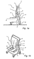
- Fig. 1a illustrates particularly the principle of the invention with a first embodiment of the invention in a side view;
- Fig. 1b illustrates the first embodiment in a perspective view;
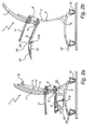
- Figs 2a and 2b illustrate, in a side view, an embodiment which is essentially identical to the one in Figs 1a and 1b, but with a different driving device, and
- Fig. 3 shows a second embodiment of the invention.
- In Figs 1a, b, the
patient chair 1 has achassis 2 with aframe 3 and a verticallyarched stand 4. Thestand 4 is connected to aunit 5 consisting of a seat of a chair and a back of achair unit 5 and adapted to roll on thestand 4. To move theunit 5 on thestand 4, there is a drive unit, in this case ahydraulic cylinder assembly 9, the ends of which are articulated at suitable points on thechassis 2 and the roller bearingarrangement 8. It is indicated by the dashed lines in Fig. la that - with the drive unit activated - theunit 5 and, thus, the patient sitting on it will automatically be continuously gradually inclined backwards when moving theunit 5 from a lower position LP to an upper position HP, and vice versa when moving it in the other direction. To this end, theback 7 of the chair preferably has a curvature corresponding to the curvature of thestand 4. - As is evident from the Figures - and obvious to a person skilled in the art - the
chassis 2 is designed for stability, so that the patient chair does not overturn with the patient sitting in it and being moved up and down. The convexity of thestand 4 is here directed forward, and thestand 4 is fixed to the rear portion of theframe 3. - It will also be obvious that said upper and lower positions HP, LP are not permanent but can be selected, for instance with regard to a comfortable working posture of the carer (tall or short carer) and/or with regard to the patient's comfort (the patient enduring a more or less pronounced backward/forward inclination) and with regard to the measure that is to be taken on the patient.
- The roller bearing
arrangement 8 is shown in more detail in Figs 2a and 2b. Thehydraulic assembly 9 is here not drawn. - In Fig. 3, the
stand 4 of thepatient chair 1 is straight and theback 7 of theunit 5 is arched. A roller bearingarrangement 8 is mounted on thestand 4 and theback 7 of the chair to guide theunit 5 in the arcuate path given by the curvature of theback 7 and extended between upper and lower positions. A drive unit, for instance ahydraulic cylinder assembly 9, mounted on thechassis 2 under theseat 6 is arranged to move theunit 5 between upper and lower positions. - The
chassis 2 preferably haswheels 10 on theframe 3, thus allowing the patient chair to be wheeled. Armrests are designated 11 and pivotable footrests are designated 30. - A person skilled in the art realises that the
unit 5 can be moved on thestand 4 by many different driving devices. For instance, a winch may connect theunit 5 to thestand 4/the roller bearing 8 and is manually operated by a crank. Instead of a roller bearing, for instance a gear arrangement can be used. Of course, it also possible to use an electric motor. A person skilled in the art is capable applying any suitable arrangement, of which there are many, for relative movement of theunit 5 and thestand 4, by motor power or manually. In case of movement by motor power, (remote) unitS can be used to stop, accelerate and retard the movement. - Nor is the shown upside-down U-shape of the
stand 4 necessary. Thestand 4 may consist of a single upright if thechassis 2 is designed with corresponding stability, to support the patient. Alternatively, thestand 4 may constitute theback 7 of the patient chair and only theseat 6 can be moved relative to this back. - The
frame 3 is suitably designed so as to allow thepatient chair 1 to be pushed under a bed, or round a toilet. For use with a toilet, theseat 6 may have anopening 12. - It goes without saying the patient chair can also be provided with various usual leg rests, armrests and headrests, which can be adjustable.
- Figs 2a and 2b show another
patient chair 1 according to the invention, provided with an advantageouscalf rest structure 20. The advantage resides in the fact that the calf rest structure takes up a small space in the inactive moved-away position (Fig. 2a), which is used, for instance, while a patient is made to sit in the patient chair, when transporting or storing the patient chair without a patient or when transporting a patient in the patient chair in narrow spaces, such as lifts and narrow bathrooms/lavatories. Thecalf rest structure 20 comprises amounting arm 21, on which a plate-shapedcalf rest pad 22 is tiltably mounted by means of atransverse arm part 21a at one end of thearm 21. The other end of themounting arm 21 is articulated to the underside of theseat 6 by means of a hinge. The hinge comprises asleeve 21b at said other end of the arm, in which apin 24 engages, which is fixed to the underside of theseat 6, close to the front edge thereof, close to the corner of the seat. Thehinge arm 21 and the calf restpad 22 when pivoting from the inactive position to the active position in Fig. 2b describe a part-circular sweeping motion in the course of which thecalf rest pad 22 will be moved behind the leg of a patient sitting in the patient chair. The carer may possibly have to first lift the leg somewhat. This pattern of movements for thecalf rest 20 facilitates the carer's work when the patient's leg is to be put on thepad 22, especially if theseat 6 is in the raised position. As is evident from Fig. 2b, thecalf rest pad 22 extends in the active position straight away from the patient chair. The active and inactive positions are end positions, defined by a slotlug connection in thesleeve 21b and thepin 24. - Moreover, Figs 2a and 2b illustrate an
electric motor winch 9 for theunit 5, the motor M being fixed to the upper part of thestand 4 and by means of aband 13 pulling and releasing, respectively, theunit 5 for movement between the lower and upper positions.
Claims (11)
- A patient chair having- a chassis (2) comprising a frame (3),- a seating device (6, 7) intended for the patient and connected to the chassis,- a driving device (9) for moving the seating device (6, 7) relative to the frame (3) in the vertical direction between a lower and an upper position, in which upper position the seating device (6, 7) and, thus, a patient sitting in it are inclined backwards relative to the lower position, characterised by- a stand (4) which belongs to the chassis (2) and extends upwards from the frame (3),- an element (4, 7) which is connected to the stand and which is continuously arched,- means (4, 7, 8) cooperating with each other and positioned on the stand and the seating device, which means are arranged to guide the seating device along the element (4) in the movement of the seating device between the lower and upper position, so that the seating device (6, 7) is continuously gradually tilted in the course of its curved movement in the vertical direction.
- A patient chair as claimed in claim 1, characterised in that the stand (4) itself constitutes the element.
- A patient chair as claimed in claim 1 or 2, characterised in that the seating device (6), 7) consists of a seat (6) of a chair and a back (7) of a chair, whick form a unit (5).
- A patient chair as claimed in any one of claims 1-3, characterised in that the element (7) is included in said means cooperating with each other and consists of a back (7) of a chair.
- A patient chair as claimed in claim 1 or 2, characterised in that the element constitutes the stand (4) and consists of a back (7) of a chair, the seating device consisting of a seat (6) of a chair.
- A patient chair as claimed in any one of claims 1-5, characterised in that the driving device is manual, for instance a hand-operated winch.
- A patient chair as claimed in any one of claims 1-6, characterised in that the driving device is a machine, for instance an electric motor or a hydraulic assembly.
- A patient chair as claimed in claim 6 or 7, characterised in that the driving device has a pulling effect on the seating device.
- A patient chair as claimed in claim 6 or 7, characterised in that the driving device has a pushing effect on the seating device.
- A patient chair as claimed in any one of claims 1-9, characterised in that the cooperating means comprise a roller bearing arrangement (8).
- A patient chair as claimed in any one of claims 1-10, characterised in that at least one plate-shaped calf rest (20) with a calf rest pad (22) is mounted on the patient chair, which calf rest is arranged by means of a joint arrangement (21b, 24) to be pivotable between an inactive end position where the extent of the calf rest pad (22) is essentially parallel to one side of the patient chair and the calf rest pad is located close to the patient chair, and an active end position where the calf rest pad is capable of supporting the patient's leg when extended, away from the patient chair.
Applications Claiming Priority (2)
| Application Number | Priority Date | Filing Date | Title |
|---|---|---|---|
| SE0301293A SE0301293L (en) | 2003-05-05 | 2003-05-05 | Patient chair with seat slidable in height |
| PCT/SE2004/000675 WO2004098479A1 (en) | 2003-05-05 | 2004-05-04 | Patient chair with a vertically movable seat |
Publications (2)
| Publication Number | Publication Date |
|---|---|
| EP1622559A1 EP1622559A1 (en) | 2006-02-08 |
| EP1622559B1 true EP1622559B1 (en) | 2007-03-21 |
Family
ID=20291196
Family Applications (1)
| Application Number | Title | Priority Date | Filing Date |
|---|---|---|---|
| EP04731107A Expired - Lifetime EP1622559B1 (en) | 2003-05-05 | 2004-05-04 | Patient chair with a vertically movable seat |
Country Status (9)
| Country | Link |
|---|---|
| US (1) | US7273255B2 (en) |
| EP (1) | EP1622559B1 (en) |
| AT (1) | ATE357201T1 (en) |
| AU (1) | AU2004235712B2 (en) |
| CA (1) | CA2524453C (en) |
| DE (1) | DE602004005443T2 (en) |
| DK (1) | DK1622559T3 (en) |
| SE (1) | SE0301293L (en) |
| WO (1) | WO2004098479A1 (en) |
Families Citing this family (32)
| Publication number | Priority date | Publication date | Assignee | Title |
|---|---|---|---|---|
| NL1028444C2 (en) * | 2005-03-02 | 2006-09-11 | Spark Design Engineering | Height adjustable reclining shower or toilet chair, has height altered by telescopic frame tubes containing linear actuators driven by electric motor |
| US8210295B2 (en) * | 2005-05-30 | 2012-07-03 | Yoshisuke Kuramoto | Electric wheelchair |
| US7716759B2 (en) * | 2005-09-28 | 2010-05-18 | Wilder William A | Patient transport apparatus |
| EP1772132A1 (en) | 2005-10-10 | 2007-04-11 | Ingenium Universal ApS | Device for assisting disabled persons |
| JP2007244817A (en) * | 2006-03-15 | 2007-09-27 | Tc Lab:Kk | Electric wheelchair with elevating function |
| ATE502614T1 (en) * | 2006-09-01 | 2011-04-15 | Spark Design & Innovation B V | ADJUSTABLE CHAIR FOR SHOWER AND TOILET |
| GB0818222D0 (en) * | 2008-10-04 | 2008-11-12 | Mountway Ltd | Improvements in and relating to chair lifts |
| NL1037497C2 (en) * | 2009-11-25 | 2011-05-26 | Gerardus Johannes Maria Pikker | CHAIR. |
| GB2489621B (en) | 2009-11-26 | 2014-03-19 | Wright Hi Lo Solutions Ltd | Chair with a height-adjustable seat |
| AU2009251224A1 (en) * | 2009-12-31 | 2011-07-14 | McKenzie, Robert Dr | Improved electric person ttransfer, load and unload device |
| EP2359793A1 (en) * | 2010-02-11 | 2011-08-24 | Invacare International Sàrl | Bath lift device |
| US20120104818A1 (en) * | 2010-04-30 | 2012-05-03 | Dennis Kimble Morris | Portable, Powered Chair Lift |
| US8534758B2 (en) | 2010-09-13 | 2013-09-17 | Tropitone Furniture Co., Inc. | Reclinable seating apparatus and method |
| US9717340B2 (en) | 2010-09-13 | 2017-08-01 | Tropitone Furniture Co., Inc. | Adjustable seating and furniture |
| US8973997B2 (en) * | 2011-07-19 | 2015-03-10 | Skip's Patents, Llc | Seat structure with sit-to-stand feature |
| JP5859265B2 (en) * | 2011-10-05 | 2016-02-10 | 日本発條株式会社 | Vehicle seat |
| DE102012102699B4 (en) * | 2012-03-29 | 2013-10-17 | medica - Medizintechnik GmbH | Aufstehtrainer |
| US8857844B1 (en) * | 2012-10-16 | 2014-10-14 | Kenneth Carl Weber | Transport device to transport user and lower and raise user to pool deck for pool access |
| CN103070751A (en) * | 2013-01-08 | 2013-05-01 | 太仓市康辉科技发展有限公司 | Multifunctional nursing chair |
| US20140306495A1 (en) * | 2013-04-11 | 2014-10-16 | University Health Network | Patient carrier |
| CA2954656A1 (en) * | 2014-07-14 | 2016-01-21 | Exokinetics, Inc. | Elevating walker chair |
| US10285883B2 (en) * | 2014-09-18 | 2019-05-14 | Motion Concepts L.P. | Adjustable chair |
| US9649236B1 (en) * | 2016-03-09 | 2017-05-16 | Active Body, Inc. | Dynamic seating and walking wheelchair with an active seat with powerlift to stand |
| US10842692B2 (en) * | 2016-04-20 | 2020-11-24 | Daniel Bryant | Elevatable and portable wheelchair |
| CN106236421B (en) * | 2016-08-23 | 2017-12-08 | 王冰凌 | Moveable electronic chair for closet |
| USD846126S1 (en) * | 2017-02-24 | 2019-04-16 | Sas Bodyfeed | Extension table |
| US11077002B1 (en) * | 2017-12-21 | 2021-08-03 | David M. Crump | Power operated lift chair |
| US11160704B2 (en) * | 2018-01-15 | 2021-11-02 | Vrmeco Llc | Joystick chair |
| US10918543B2 (en) * | 2018-09-04 | 2021-02-16 | Joseph Shea | Tracked chair |
| US11540960B2 (en) | 2018-12-07 | 2023-01-03 | Stryker Corporation | Sit to stand stair chair |
| CA3188331A1 (en) * | 2020-07-06 | 2022-01-13 | Arjo IP Holding Aktiebolag | Patient handling apparatus |
| US12653751B2 (en) * | 2021-02-26 | 2026-06-16 | Telo LLC | Multi-use mobility aid device |
Family Cites Families (40)
| Publication number | Priority date | Publication date | Assignee | Title |
|---|---|---|---|---|
| US2572149A (en) * | 1949-06-03 | 1951-10-23 | Sylvia Hind | Wheel chair attachment |
| GB1237808A (en) * | 1968-09-10 | 1971-06-30 | Johannes Nicolaas Van Rhyn | Apparatus for assisting invalids to stand |
| US3589769A (en) * | 1969-05-19 | 1971-06-29 | Peter W Bressler | Nding wheelchair |
| US3964786A (en) * | 1974-12-20 | 1976-06-22 | David Mashuda | Mechanized wheelchair |
| US4054319A (en) * | 1975-10-23 | 1977-10-18 | The United States Of America As Represented By The Secretary Of The Navy | Stand-aid invalid wheelchair |
| CH608186A5 (en) * | 1976-01-30 | 1978-12-29 | Valutec Ag | |
| US4155416A (en) * | 1977-01-26 | 1979-05-22 | Ausmus Donald L | Occupant-operated mobile work vehicle for paraplegics |
| US4249774A (en) * | 1979-02-22 | 1981-02-10 | Andreasson Sven A | Invalid chair |
| US4390076A (en) * | 1979-08-01 | 1983-06-28 | The United States Of America As Represented By The Secretary Of The Navy | Integrated wheelchair and ambulator |
| US4456086A (en) * | 1979-08-01 | 1984-06-26 | The United States Of America As Represented By The Secretary Of The Navy | Integrated wheelchair and ambulator |
| SE431056B (en) * | 1980-05-05 | 1984-01-16 | Hans Arne Valentin Johansson | PATIENT LIFT SITS |
| US4437537A (en) * | 1982-01-25 | 1984-03-20 | Ausmus Donald L | Vehicle for supporting handicapped occupants |
| JPS58165847A (en) * | 1982-03-26 | 1983-09-30 | 社会福祉法人神奈川県総合リハビリテ−シヨン事業団 | Wheelchair |
| US4569556A (en) * | 1983-12-29 | 1986-02-11 | Societe A Responsabilite Limitee International Diffusion Consommateur I.D.C | Elevator device for wheelchair and wheelchair incorporating same |
| DE3566951D1 (en) * | 1984-04-06 | 1989-02-02 | Valutec Ag | Lifting chair |
| US4802542A (en) * | 1986-08-25 | 1989-02-07 | Falcon Rehabilitation Products, Inc. | Powered walker |
| US4809804A (en) * | 1986-08-25 | 1989-03-07 | Falcon Rehabilitation Products, Inc. | Combination wheelchair and walker apparatus |
| US5137102A (en) * | 1986-08-25 | 1992-08-11 | Retec Pr, Inc. | Combination wheelchair and walker apparatus |
| EP0299476A1 (en) * | 1987-07-15 | 1989-01-18 | Kenneth Brian Smith | Wheelchair |
| US4948156A (en) * | 1989-03-13 | 1990-08-14 | Legg-On | Standing lift and support for wheelchair user |
| US5054852A (en) * | 1989-08-30 | 1991-10-08 | Tholkes Alan L | Utility station with controlled seating |
| US5096008A (en) * | 1990-09-24 | 1992-03-17 | Jericho Corporation | Stand-up wheelchair |
| US5265689A (en) * | 1991-01-14 | 1993-11-30 | Kauffmann Ricardo M | Prosthetic device for lifting and lowering a person thereon |
| US5346280A (en) * | 1992-03-31 | 1994-09-13 | Deumite Norman A | Chair with automatic standing aid |
| US5484151A (en) * | 1993-11-18 | 1996-01-16 | Tholkes; Alan L. | Mobile standing aid |
| NO301151B1 (en) * | 1995-01-31 | 1997-09-22 | Tryggve Sletteboe | Method for using ergonometrically interacting adjustment of seating equipment |
| DK0815822T3 (en) * | 1996-06-27 | 1999-09-13 | Levo Ag Dottikon | Upright wheelchair |
| US6053519A (en) * | 1996-11-13 | 2000-04-25 | The Advanced Technologies Corp. | Occupant operated motorized vehicle with lift assist |
| US5800016A (en) * | 1997-03-10 | 1998-09-01 | Allred; Lyle | Elevating chair |
| JPH10314231A (en) * | 1997-05-14 | 1998-12-02 | Exedy Corp | Traveling vehicle with seat attitude holding mechanism |
| US6244662B1 (en) * | 1997-10-22 | 2001-06-12 | I.D.C. Medical | Elevator chair of adjustable seat depth |
| US6125957A (en) * | 1998-02-10 | 2000-10-03 | Kauffmann; Ricardo M. | Prosthetic apparatus for supporting a user in sitting or standing positions |
| FR2779945B1 (en) * | 1998-06-23 | 2000-11-10 | Internat Diffusion Consommateu | ARTICULATING NUT FOR A HANDICAP ARMCHAIR AND ARMCHAIR USING THE SAME |
| US6126186A (en) * | 1998-11-09 | 2000-10-03 | Invacare Corporation | Constant center of gravity tilt seat of a wheelchair |
| US6192533B1 (en) * | 1999-04-02 | 2001-02-27 | I.D.C. Medical | Elevator chairs for the handicapped and invalids |
| US6619681B2 (en) * | 2001-05-16 | 2003-09-16 | Delano Association For The Developmentally Disabled | Dynamic seating and walking wheelchair |
| JP2003019055A (en) * | 2001-07-11 | 2003-01-21 | Komura Seisakusho:Kk | Lifting chair |
| DE20116111U1 (en) * | 2001-10-01 | 2002-02-28 | Hoyer GmbH, 35510 Butzbach | Mobile, reclining therapy bath chair |
| US6811220B2 (en) * | 2001-10-02 | 2004-11-02 | North American Manufacturing Company, Inc. | Apparatus for automatically raising and lowering a seat |
| BR0105828B1 (en) * | 2001-11-13 | 2009-01-13 | device for the mobility of the disabled. |
-
2003
- 2003-05-05 SE SE0301293A patent/SE0301293L/en not_active IP Right Cessation
-
2004
- 2004-05-04 DE DE602004005443T patent/DE602004005443T2/en not_active Expired - Lifetime
- 2004-05-04 US US10/555,585 patent/US7273255B2/en not_active Expired - Lifetime
- 2004-05-04 AT AT04731107T patent/ATE357201T1/en not_active IP Right Cessation
- 2004-05-04 CA CA2524453A patent/CA2524453C/en not_active Expired - Lifetime
- 2004-05-04 EP EP04731107A patent/EP1622559B1/en not_active Expired - Lifetime
- 2004-05-04 DK DK04731107T patent/DK1622559T3/en active
- 2004-05-04 AU AU2004235712A patent/AU2004235712B2/en not_active Expired
- 2004-05-04 WO PCT/SE2004/000675 patent/WO2004098479A1/en not_active Ceased
Also Published As
| Publication number | Publication date |
|---|---|
| US20060220429A1 (en) | 2006-10-05 |
| AU2004235712A1 (en) | 2004-11-18 |
| US7273255B2 (en) | 2007-09-25 |
| ATE357201T1 (en) | 2007-04-15 |
| EP1622559A1 (en) | 2006-02-08 |
| SE522825C2 (en) | 2004-03-09 |
| SE0301293D0 (en) | 2003-05-05 |
| CA2524453C (en) | 2012-07-03 |
| DE602004005443D1 (en) | 2007-05-03 |
| AU2004235712B2 (en) | 2010-11-11 |
| DE602004005443T2 (en) | 2007-11-29 |
| DK1622559T3 (en) | 2007-07-30 |
| SE0301293L (en) | 2004-03-09 |
| CA2524453A1 (en) | 2004-11-18 |
| WO2004098479A1 (en) | 2004-11-18 |
Similar Documents
| Publication | Publication Date | Title |
|---|---|---|
| AU2004235712B2 (en) | Patient chair with a vertically movable seat | |
| US5011175A (en) | Wheelchair | |
| US5203610A (en) | Reclining lift chair having wheels for transport | |
| CA2692434C (en) | Stand-up unit for stand-up wheelchairs and chairs, particularly therapy chairs | |
| US5984411A (en) | Elevator chair | |
| US11006753B2 (en) | Armchair | |
| US20110121626A1 (en) | Lift chair | |
| KR20080042033A (en) | Standing wheelchair | |
| US20050039263A1 (en) | Adjustable beds or recliners | |
| US7585019B2 (en) | Seat reclining mechanism for power wheelchair | |
| AU2004235713B2 (en) | Calf rest for patient chair | |
| EP0236304A1 (en) | An arrangement in a wheel chair | |
| KR20210037237A (en) | Standing-assisted chair | |
| US5046571A (en) | Vertically adjustable wheel chair | |
| US20040049841A1 (en) | Commode chair | |
| JP5313655B2 (en) | Office wheelchair | |
| KR20130037603A (en) | Chair linking up with cabinet for patient | |
| WO2008150301A1 (en) | Chair device | |
| KR20130003231A (en) | Toilet bowl seat assembly | |
| JP2002136377A (en) | Chair | |
| JPH0537796Y2 (en) | ||
| US20020079727A1 (en) | Armchair with seatlift | |
| JP3068470U (en) | Adjustable chair | |
| JPH09285499A (en) | Chair with lifting function | |
| JPS6441351U (en) |
Legal Events
| Date | Code | Title | Description |
|---|---|---|---|
| PUAI | Public reference made under article 153(3) epc to a published international application that has entered the european phase |
Free format text: ORIGINAL CODE: 0009012 |
|
| 17P | Request for examination filed |
Effective date: 20051129 |
|
| AK | Designated contracting states |
Kind code of ref document: A1 Designated state(s): AT BE BG CH CY CZ DE DK EE ES FI FR GB GR HU IE IT LI LU MC NL PL PT RO SE SI SK TR |
|
| RAP1 | Party data changed (applicant data changed or rights of an application transferred) |
Owner name: ARJO HOSPITAL EQUIPMENT AB |
|
| DAX | Request for extension of the european patent (deleted) | ||
| GRAP | Despatch of communication of intention to grant a patent |
Free format text: ORIGINAL CODE: EPIDOSNIGR1 |
|
| GRAS | Grant fee paid |
Free format text: ORIGINAL CODE: EPIDOSNIGR3 |
|
| GRAA | (expected) grant |
Free format text: ORIGINAL CODE: 0009210 |
|
| AK | Designated contracting states |
Kind code of ref document: B1 Designated state(s): AT BE BG CH CY CZ DE DK EE ES FI FR GB GR HU IE IT LI LU MC NL PL PT RO SE SI SK TR |
|
| PG25 | Lapsed in a contracting state [announced via postgrant information from national office to epo] |
Ref country code: SI Free format text: LAPSE BECAUSE OF FAILURE TO SUBMIT A TRANSLATION OF THE DESCRIPTION OR TO PAY THE FEE WITHIN THE PRESCRIBED TIME-LIMIT Effective date: 20070321 Ref country code: LI Free format text: LAPSE BECAUSE OF FAILURE TO SUBMIT A TRANSLATION OF THE DESCRIPTION OR TO PAY THE FEE WITHIN THE PRESCRIBED TIME-LIMIT Effective date: 20070321 Ref country code: CH Free format text: LAPSE BECAUSE OF FAILURE TO SUBMIT A TRANSLATION OF THE DESCRIPTION OR TO PAY THE FEE WITHIN THE PRESCRIBED TIME-LIMIT Effective date: 20070321 Ref country code: FI Free format text: LAPSE BECAUSE OF FAILURE TO SUBMIT A TRANSLATION OF THE DESCRIPTION OR TO PAY THE FEE WITHIN THE PRESCRIBED TIME-LIMIT Effective date: 20070321 Ref country code: PL Free format text: LAPSE BECAUSE OF FAILURE TO SUBMIT A TRANSLATION OF THE DESCRIPTION OR TO PAY THE FEE WITHIN THE PRESCRIBED TIME-LIMIT Effective date: 20070321 Ref country code: AT Free format text: LAPSE BECAUSE OF FAILURE TO SUBMIT A TRANSLATION OF THE DESCRIPTION OR TO PAY THE FEE WITHIN THE PRESCRIBED TIME-LIMIT Effective date: 20070321 |
|
| REG | Reference to a national code |
Ref country code: GB Ref legal event code: FG4D |
|
| REG | Reference to a national code |
Ref country code: CH Ref legal event code: EP |
|
| REF | Corresponds to: |
Ref document number: 602004005443 Country of ref document: DE Date of ref document: 20070503 Kind code of ref document: P |
|
| REG | Reference to a national code |
Ref country code: IE Ref legal event code: FG4D |
|
| PG25 | Lapsed in a contracting state [announced via postgrant information from national office to epo] |
Ref country code: SE Free format text: LAPSE BECAUSE OF FAILURE TO SUBMIT A TRANSLATION OF THE DESCRIPTION OR TO PAY THE FEE WITHIN THE PRESCRIBED TIME-LIMIT Effective date: 20070621 |
|
| PG25 | Lapsed in a contracting state [announced via postgrant information from national office to epo] |
Ref country code: ES Free format text: LAPSE BECAUSE OF FAILURE TO SUBMIT A TRANSLATION OF THE DESCRIPTION OR TO PAY THE FEE WITHIN THE PRESCRIBED TIME-LIMIT Effective date: 20070702 |
|
| REG | Reference to a national code |
Ref country code: DK Ref legal event code: T3 |
|
| PG25 | Lapsed in a contracting state [announced via postgrant information from national office to epo] |
Ref country code: PT Free format text: LAPSE BECAUSE OF FAILURE TO SUBMIT A TRANSLATION OF THE DESCRIPTION OR TO PAY THE FEE WITHIN THE PRESCRIBED TIME-LIMIT Effective date: 20070821 |
|
| REG | Reference to a national code |
Ref country code: CH Ref legal event code: PL |
|
| PG25 | Lapsed in a contracting state [announced via postgrant information from national office to epo] |
Ref country code: SK Free format text: LAPSE BECAUSE OF FAILURE TO SUBMIT A TRANSLATION OF THE DESCRIPTION OR TO PAY THE FEE WITHIN THE PRESCRIBED TIME-LIMIT Effective date: 20070321 |
|
| PG25 | Lapsed in a contracting state [announced via postgrant information from national office to epo] |
Ref country code: CZ Free format text: LAPSE BECAUSE OF FAILURE TO SUBMIT A TRANSLATION OF THE DESCRIPTION OR TO PAY THE FEE WITHIN THE PRESCRIBED TIME-LIMIT Effective date: 20070321 Ref country code: RO Free format text: LAPSE BECAUSE OF FAILURE TO SUBMIT A TRANSLATION OF THE DESCRIPTION OR TO PAY THE FEE WITHIN THE PRESCRIBED TIME-LIMIT Effective date: 20070321 |
|
| PLBE | No opposition filed within time limit |
Free format text: ORIGINAL CODE: 0009261 |
|
| STAA | Information on the status of an ep patent application or granted ep patent |
Free format text: STATUS: NO OPPOSITION FILED WITHIN TIME LIMIT |
|
| PG25 | Lapsed in a contracting state [announced via postgrant information from national office to epo] |
Ref country code: MC Free format text: LAPSE BECAUSE OF NON-PAYMENT OF DUE FEES Effective date: 20070531 |
|
| 26N | No opposition filed |
Effective date: 20071227 |
|
| PG25 | Lapsed in a contracting state [announced via postgrant information from national office to epo] |
Ref country code: IT Free format text: LAPSE BECAUSE OF FAILURE TO SUBMIT A TRANSLATION OF THE DESCRIPTION OR TO PAY THE FEE WITHIN THE PRESCRIBED TIME-LIMIT Effective date: 20070321 Ref country code: GR Free format text: LAPSE BECAUSE OF FAILURE TO SUBMIT A TRANSLATION OF THE DESCRIPTION OR TO PAY THE FEE WITHIN THE PRESCRIBED TIME-LIMIT Effective date: 20070622 |
|
| PG25 | Lapsed in a contracting state [announced via postgrant information from national office to epo] |
Ref country code: IE Free format text: LAPSE BECAUSE OF NON-PAYMENT OF DUE FEES Effective date: 20070504 |
|
| PG25 | Lapsed in a contracting state [announced via postgrant information from national office to epo] |
Ref country code: EE Free format text: LAPSE BECAUSE OF FAILURE TO SUBMIT A TRANSLATION OF THE DESCRIPTION OR TO PAY THE FEE WITHIN THE PRESCRIBED TIME-LIMIT Effective date: 20070321 |
|
| PG25 | Lapsed in a contracting state [announced via postgrant information from national office to epo] |
Ref country code: CY Free format text: LAPSE BECAUSE OF FAILURE TO SUBMIT A TRANSLATION OF THE DESCRIPTION OR TO PAY THE FEE WITHIN THE PRESCRIBED TIME-LIMIT Effective date: 20070321 |
|
| PG25 | Lapsed in a contracting state [announced via postgrant information from national office to epo] |
Ref country code: LU Free format text: LAPSE BECAUSE OF NON-PAYMENT OF DUE FEES Effective date: 20070504 Ref country code: BG Free format text: LAPSE BECAUSE OF FAILURE TO SUBMIT A TRANSLATION OF THE DESCRIPTION OR TO PAY THE FEE WITHIN THE PRESCRIBED TIME-LIMIT Effective date: 20070621 |
|
| PG25 | Lapsed in a contracting state [announced via postgrant information from national office to epo] |
Ref country code: TR Free format text: LAPSE BECAUSE OF FAILURE TO SUBMIT A TRANSLATION OF THE DESCRIPTION OR TO PAY THE FEE WITHIN THE PRESCRIBED TIME-LIMIT Effective date: 20070321 Ref country code: HU Free format text: LAPSE BECAUSE OF FAILURE TO SUBMIT A TRANSLATION OF THE DESCRIPTION OR TO PAY THE FEE WITHIN THE PRESCRIBED TIME-LIMIT Effective date: 20070922 |
|
| PGFP | Annual fee paid to national office [announced via postgrant information from national office to epo] |
Ref country code: BE Payment date: 20140527 Year of fee payment: 11 |
|
| REG | Reference to a national code |
Ref country code: FR Ref legal event code: PLFP Year of fee payment: 13 |
|
| REG | Reference to a national code |
Ref country code: FR Ref legal event code: PLFP Year of fee payment: 14 |
|
| PG25 | Lapsed in a contracting state [announced via postgrant information from national office to epo] |
Ref country code: BE Free format text: LAPSE BECAUSE OF NON-PAYMENT OF DUE FEES Effective date: 20150531 |
|
| REG | Reference to a national code |
Ref country code: DE Ref legal event code: R082 Ref document number: 602004005443 Country of ref document: DE Representative=s name: ZACCO LEGAL RECHTSANWALTSGESELLSCHAFT MBH, DE Ref country code: DE Ref legal event code: R082 Ref document number: 602004005443 Country of ref document: DE Representative=s name: ZACCO DR. PETERS UND PARTNER, DE Ref country code: DE Ref legal event code: R082 Ref document number: 602004005443 Country of ref document: DE Representative=s name: ZACCO PATENTANWALTS- UND RECHTSANWALTSGESELLSC, DE |
|
| REG | Reference to a national code |
Ref country code: FR Ref legal event code: PLFP Year of fee payment: 15 |
|
| REG | Reference to a national code |
Ref country code: DE Ref legal event code: R082 Ref document number: 602004005443 Country of ref document: DE Representative=s name: ZACCO LEGAL RECHTSANWALTSGESELLSCHAFT MBH, DE |
|
| PGFP | Annual fee paid to national office [announced via postgrant information from national office to epo] |
Ref country code: NL Payment date: 20230519 Year of fee payment: 20 Ref country code: FR Payment date: 20230525 Year of fee payment: 20 Ref country code: DK Payment date: 20230524 Year of fee payment: 20 Ref country code: DE Payment date: 20220620 Year of fee payment: 20 |
|
| PGFP | Annual fee paid to national office [announced via postgrant information from national office to epo] |
Ref country code: GB Payment date: 20230522 Year of fee payment: 20 |
|
| REG | Reference to a national code |
Ref country code: DE Ref legal event code: R071 Ref document number: 602004005443 Country of ref document: DE |
|
| REG | Reference to a national code |
Ref country code: DK Ref legal event code: EUP Expiry date: 20240504 |
|
| REG | Reference to a national code |
Ref country code: NL Ref legal event code: MK Effective date: 20240503 |
|
| REG | Reference to a national code |
Ref country code: GB Ref legal event code: PE20 Expiry date: 20240503 |
|
| PG25 | Lapsed in a contracting state [announced via postgrant information from national office to epo] |
Ref country code: GB Free format text: LAPSE BECAUSE OF EXPIRATION OF PROTECTION Effective date: 20240503 |
|
| PG25 | Lapsed in a contracting state [announced via postgrant information from national office to epo] |
Ref country code: GB Free format text: LAPSE BECAUSE OF EXPIRATION OF PROTECTION Effective date: 20240503 |