EP1622250A2 - Control device of electric motor - Google Patents
Control device of electric motor Download PDFInfo
- Publication number
- EP1622250A2 EP1622250A2 EP05015648A EP05015648A EP1622250A2 EP 1622250 A2 EP1622250 A2 EP 1622250A2 EP 05015648 A EP05015648 A EP 05015648A EP 05015648 A EP05015648 A EP 05015648A EP 1622250 A2 EP1622250 A2 EP 1622250A2
- Authority
- EP
- European Patent Office
- Prior art keywords
- motor
- velocity
- judging
- control device
- monitoring
- Prior art date
- Legal status (The legal status is an assumption and is not a legal conclusion. Google has not performed a legal analysis and makes no representation as to the accuracy of the status listed.)
- Granted
Links
- 238000012544 monitoring process Methods 0.000 claims abstract description 41
- 230000002159 abnormal effect Effects 0.000 claims abstract description 29
- 230000003247 decreasing effect Effects 0.000 claims description 3
- 238000000034 method Methods 0.000 description 15
- 230000007423 decrease Effects 0.000 description 2
- 238000012986 modification Methods 0.000 description 1
- 230000004048 modification Effects 0.000 description 1
Images


Classifications
-
- H—ELECTRICITY
- H02—GENERATION; CONVERSION OR DISTRIBUTION OF ELECTRIC POWER
- H02P—CONTROL OR REGULATION OF ELECTRIC MOTORS, ELECTRIC GENERATORS OR DYNAMO-ELECTRIC CONVERTERS; CONTROLLING TRANSFORMERS, REACTORS OR CHOKE COILS
- H02P6/00—Arrangements for controlling synchronous motors or other dynamo-electric motors using electronic commutation dependent on the rotor position; Electronic commutators therefor
- H02P6/24—Arrangements for stopping
-
- H—ELECTRICITY
- H02—GENERATION; CONVERSION OR DISTRIBUTION OF ELECTRIC POWER
- H02P—CONTROL OR REGULATION OF ELECTRIC MOTORS, ELECTRIC GENERATORS OR DYNAMO-ELECTRIC CONVERTERS; CONTROLLING TRANSFORMERS, REACTORS OR CHOKE COILS
- H02P29/00—Arrangements for regulating or controlling electric motors, appropriate for both AC and DC motors
- H02P29/02—Providing protection against overload without automatic interruption of supply
- H02P29/032—Preventing damage to the motor, e.g. setting individual current limits for different drive conditions
-
- H—ELECTRICITY
- H02—GENERATION; CONVERSION OR DISTRIBUTION OF ELECTRIC POWER
- H02P—CONTROL OR REGULATION OF ELECTRIC MOTORS, ELECTRIC GENERATORS OR DYNAMO-ELECTRIC CONVERTERS; CONTROLLING TRANSFORMERS, REACTORS OR CHOKE COILS
- H02P3/00—Arrangements for stopping or slowing electric motors, generators, or dynamo-electric converters
- H02P3/02—Details of stopping control
Definitions
- the present invention relates to a control device of an electrical motor.
- the runaway of an electric power system may be avoided.
- the stopping time of the motor becomes longer because the motor is driven by inertia after the cutting-off of the power. Accordingly, the stopping distance of a movable part driven by the motor, in a device or a system, also becomes longer.
- An object of the present invention is to provide a control device for controlling an electric motor, when the motor is intended to decelerated and stopped, in order to resolve the above problem.
- the present invention provides a control device of an electrical motor, comprising: a control part for controlling decelerating and stopping operations; a monitoring part for monitoring the operations of the electric motor; and a judging part for judging whether the velocity of the electric motor monitored by the monitoring part is abnormal while the control part controls the motor so as to decelerate and stop the motor; wherein the judging part forcibly cuts off power to the electric motor via a circuit breaker when the judging part judges that the velocity of the motor is abnormal.
- the monitoring part may monitor the velocity of the electric motor at a predetermined interval while the motor is decelerated, the judging part may judge that the velocity is abnormal when the velocity monitored by the monitoring part is not continuously decreasing.
- the monitoring part may monitor the velocity of the electric motor after a predetermined time has passed from the beginning of deceleration of the motor, the judging part may judge that the velocity is abnormal when the velocity monitored by the monitoring part is equal to or larger than a predetermined threshold.
- the monitoring part may monitor the velocity of the electric motor at a predetermined interval while the motor is decelerated and the judging part may judge whether the velocity is abnormal or not, based on a result of comparison between the velocity monitored by the monitoring part and a commanded velocity calculated at a predetermined interval for the motor.
- the control device may include a plurality of the monitoring parts and a plurality of the judging parts each associated with each monitoring part. In this case, at least one of the judging parts forcibly cuts off power to the electric motor via the circuit breaker when the judging part judges that the velocity of the motor is abnormal.
- the monitoring part or the judging part is activated by an emergency stop signal.
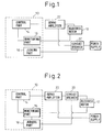
- Fig. 1 shows a preferable configuration of a control device 10 according to the invention.
- the control device 10 is a CNC device, for example, and includes a control part 14 for controlling decelerating and stopping operations of an electric motor 12, a monitoring part 16 for monitoring the operations of the motor 12, and a judging part 18 for judging whether the velocity of the motor 12 monitored by the monitoring part 16 is abnormal while the control part 14 controls the motor 12 so as to decelerate and stop the motor.
- the monitoring part 16 may monitor other parameters, such as torque and current, representing an operating state of the motor 12.
- the judging part 18 may send a power cut command to a circuit breaker 20 capable of forcibly cutting off power to the motor 12, when the judging part 18 judges that the velocity of the motor 12 is abnormal.
- the control part 14 may control the motor 12 via a servo amplifier 22.
- the breaker 20 may cut off the power to the motor 12 via the servo amplifier 22.
- Fig. 2 shows another preferable configuration of a control device according to the invention. This configuration is different from that of Fig. 1 in that the breaker 20 cuts off the power to the motor 12 without a servo amplifier being between them.
- Fig. 3 is a flowchart showing control of the electric motor 12 by using the control device 10.
- step 102 it is judged whether the motor 12 is decelerating. If not, the motor 12 is normally operated (step 104) and the process terminates. While the motor 12 is being decelerated, the process progresses to step 106 and the judging part 18 judges whether the decelerating operation or the velocity of the motor is abnormal or not, based on the velocity monitored by the monitoring part 16. When the decelerating is judged to be normal, the process progresses to step 108 and the control part 14 continues controlling the operation, then, the process terminates.
- step 106 determines whether the velocity of the motor is judged to be abnormal in step 106. If the velocity of the motor is judged to be abnormal in step 106, it should be considered that the decelerating operation includes some kind of problem. Therefore, the process progresses to step 110 for stopping the decelerating operation. Further, the process progresses to step 112 in which the circuit breaker 20 cuts off the power to the motor 12 and, then, the process terminates. The series of steps described above is repeated at a predetermined interval.
- Figs. 4 and 5 show the changes of the velocity of the motor during the decelerating operation by the control device or a control way of the invention, in comparison with that of the prior art.
- Fig. 4 corresponds to a case in which the velocity of the motor is judged to be normal (i.e., steps 106 ⁇ 108 in Fig. 3) and
- Fig. 5 corresponds to a case in which the velocity of the motor is judged to be abnormal (i.e., steps 106 ⁇ 110 ⁇ 112 in Fig. 3).
- the velocity of the motor is rapidly decreased just after the power is cut off, however, the deceleration rate of the velocity is gradually lowered as time passes.
- the area S1 may be smaller than the area S2. Therefore, by using the control device of the invention, a stopping time of the electric motor and a stopping distance of a movable part of a device or a system driven by the electric motor may be shortened.
- the velocity of the motor may instantly increase, as shown by the solid line of the graph, as the power is supplied to the motor at time t3.
- the judging part 18 activates the circuit breaker 20 upon recognizing the problem with the motor. Therefore, the velocity of the motor decreases after time t4 when the breaker 20 is activated.
- the change profile of the velocity of the motor after the breaker 20 is activated is generally the same as that of prior art (the dashed line) after time t1. Also in this case, therefore, the area S1 may be smaller than the area S2, whereby the stopping time of the motor and the stopping distance of the movable part driven by the motor may be shortened.
- step 106 for judging whether the velocity of the motor during the decelerating operation is abnormal or not, some concrete methods may be possible.
- the judging part 18 judges the velocity of the motor to be abnormal when the current velocity monitored by the monitoring part 16 is larger than the last velocity, whereby the process progresses to step 110.
- the judging part 18 judges the velocity of the motor to be normal when the current velocity is equal to or smaller than the last velocity, whereby the process progresses to step 108.
- the condition in which the velocity of the motor monitored at a predetermined interval always decreases or does not change, is judged to be normal.
- Other steps of Fig. 6 may be the same as the corresponding steps of Fig. 3.
- step 1062 shown in Fig. 7 the judging part 18 judges whether a predetermined time has passed or not. If the predetermined time has not passed yet, the process progresses to step 1063 for time-integration and then terminates. When the predetermined time has passed, the process progresses to step 1064 in which the judging part judges whether the velocity of the motor is equal to or smaller than a predetermined threshold. If yes, the velocity of the motor is judged to be normal and the process progresses to step 108. Contrarily, the judging part 18 judges the velocity of the motor to be abnormal when the velocity is larger than the threshold, whereby the process progresses to step 110.
- the judging part 18 judges whether a predetermined time has passed or not. If the predetermined time has not passed yet, the process progresses to step 1063 for time-integration and then terminates. When the predetermined time has passed, the process progresses to step 1064 in which the judging part judges whether the velocity of the motor is equal to or smaller than a predetermined threshold. If yes, the
- step 103 is inserted between steps 102 and 104 for clearing the integrated time in step 1063.
- Other steps of Fig. 7 may be the same as corresponding steps of Fig. 3.
- the monitoring part 16 monitors the velocity of the motor during the decelerating operation at a predetermined interval. Further, the judging part 18 judges whether the velocity of the motor is abnormal, or not, based on a result of comparison between the velocity monitored by the monitoring part and a commanded velocity calculated at a predetermined interval for the motor. Concretely, in step 1065 shown in Fig. 8, the judging part 18 compares the real velocity monitored by the monitoring part 16 with a commanded decelerating velocity given to the motor. If the difference between the monitored velocity and the commanded velocity is not within a predetermined range, the velocity of the motor is judged to be abnormal and the process progresses to step 110 or, otherwise, to step 108. By repeating this series of steps at a predetermined interval, the monitored velocity is compared with the commanded velocity at the predetermined interval. Other steps of Fig. 8 may be the same as corresponding steps of Fig. 3.
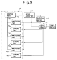
- Fig. 9 is a view showing an example of application of a configuration of a control device according to the invention.
- the control device of Fig. 9 is different from the control device of Fig. 3, in that the control device includes a plurality of (three in this example) monitoring parts 16a - 16c and a plurality of judging parts each associated with each monitoring part 18a - 18c.
- the circuit breaker 20 is activated. Due to this constitution, if one of the monitoring parts or the judging parts is out of order, other judging parts may judge the velocity of the motor. Therefore, an abnormal velocity of the motor or a problem with the decelerating operation may be quickly and surely recognized.
- the major object of the invention is to provide a control device capable of reducing stopping time of an electric motor, and the stopping distance of a movable part driven by the motor, when a decelerating operation for the motor includes some kind of problem, in comparison with the case in which the power to the motor is forcibly cut off. Therefore, it is preferable that the monitoring part and the judging part of the control device may be activated only in an emergency stop of the motor.
- the monitoring part and the judging part are configured to be activated by an emergency stop signal outputted when an operator pushes an emergency stop button or another sensor detects a problem.
- the velocity of the motor may be controlled when the decelerating operation is normal, otherwise, the power to the motor may be forcibly cut off when the decelerating operation is out of order. Therefore, the stopping time and the stopping distance of the motor may be reduced, while the risk of runaway of the motor is eliminated.
Landscapes
- Engineering & Computer Science (AREA)
- Power Engineering (AREA)
- Control Of Electric Motors In General (AREA)
- Stopping Of Electric Motors (AREA)
- Control Of Ac Motors In General (AREA)
Abstract
Description
- The present invention relates to a control device of an electrical motor.
- In the prior art, it has been considered to be safe for a control device of an electric motor to forcibly cut off power to the motor in order to stop the motor. This is because the risk of runaway of the motor is not completely eliminated when the motor is stopped without cutting off the power by, for example, a slowdown control, in which the power is continuously supplied to the motor.
- In the above forcible cutting-off of the power, the runaway of an electric power system may be avoided. However, the stopping time of the motor becomes longer because the motor is driven by inertia after the cutting-off of the power. Accordingly, the stopping distance of a movable part driven by the motor, in a device or a system, also becomes longer.
- An object of the present invention is to provide a control device for controlling an electric motor, when the motor is intended to decelerated and stopped, in order to resolve the above problem.
- In order to achieve the object, the present invention provides a control device of an electrical motor, comprising: a control part for controlling decelerating and stopping operations; a monitoring part for monitoring the operations of the electric motor; and a judging part for judging whether the velocity of the electric motor monitored by the monitoring part is abnormal while the control part controls the motor so as to decelerate and stop the motor; wherein the judging part forcibly cuts off power to the electric motor via a circuit breaker when the judging part judges that the velocity of the motor is abnormal.
- The monitoring part may monitor the velocity of the electric motor at a predetermined interval while the motor is decelerated, the judging part may judge that the velocity is abnormal when the velocity monitored by the monitoring part is not continuously decreasing.
- Alternatively, the monitoring part may monitor the velocity of the electric motor after a predetermined time has passed from the beginning of deceleration of the motor, the judging part may judge that the velocity is abnormal when the velocity monitored by the monitoring part is equal to or larger than a predetermined threshold.
- Alternatively, the monitoring part may monitor the velocity of the electric motor at a predetermined interval while the motor is decelerated and the judging part may judge whether the velocity is abnormal or not, based on a result of comparison between the velocity monitored by the monitoring part and a commanded velocity calculated at a predetermined interval for the motor.
- The control device may include a plurality of the monitoring parts and a plurality of the judging parts each associated with each monitoring part. In this case, at least one of the judging parts forcibly cuts off power to the electric motor via the circuit breaker when the judging part judges that the velocity of the motor is abnormal.
- It is preferable that the monitoring part or the judging part is activated by an emergency stop signal.
- The above and other objects, features and advantages of the present invention will be made more apparent by the following description of the preferred embodiments thereof, with reference to the accompanying drawings, wherein:
- Fig. 1 shows a preferable configuration of a control device according to the invention;
- Fig. 2 shows another preferable configuration of a control device according to the invention;
- Fig. 3 is a flowchart showing a control way of an electric motor by using the control device of the invention;
- Fig. 4 is a graph indicating changes of the velocity of the motor without disorder during control of deceleration of the motor, using a solid line and a dashed line representing the invention and the prior art, respectively;
- Fig. 5 is a graph, in relation to Fig. 4, indicating changes of the velocity of the motor with disorder during control of deceleration of the motor, using a solid line and a dashed line representing the invention and the prior art, respectively;
- Fig. 6 is a flowchart, in relation to Fig. 3, showing steps of a first embodiment for judging whether the velocity of the motor is abnormal or not;
- Fig. 7 is a flowchart, in relation to Fig. 3, showing steps of a second embodiment for judging whether the velocity of the motor is abnormal or not;
- Fig. 8 is a flowchart, in relation to Fig. 3, showing steps of a third embodiment for judging whether the velocity of the motor is abnormal or not; and
- Fig. 9 is a view showing an example of application of a configuration of a control device according to the invention.
- The detail of the invention will be described below with reference to the drawings.
- Fig. 1 shows a preferable configuration of a
control device 10 according to the invention. Thecontrol device 10 is a CNC device, for example, and includes acontrol part 14 for controlling decelerating and stopping operations of anelectric motor 12, amonitoring part 16 for monitoring the operations of themotor 12, and ajudging part 18 for judging whether the velocity of themotor 12 monitored by themonitoring part 16 is abnormal while thecontrol part 14 controls themotor 12 so as to decelerate and stop the motor. Themonitoring part 16 may monitor other parameters, such as torque and current, representing an operating state of themotor 12. The judgingpart 18 may send a power cut command to acircuit breaker 20 capable of forcibly cutting off power to themotor 12, when the judgingpart 18 judges that the velocity of themotor 12 is abnormal. In addition, as shown in Fig. 1, thecontrol part 14 may control themotor 12 via aservo amplifier 22. Similarly, thebreaker 20 may cut off the power to themotor 12 via theservo amplifier 22. - Fig. 2 shows another preferable configuration of a control device according to the invention. This configuration is different from that of Fig. 1 in that the
breaker 20 cuts off the power to themotor 12 without a servo amplifier being between them. - Fig. 3 is a flowchart showing control of the
electric motor 12 by using thecontrol device 10. First, isstep 102, it is judged whether themotor 12 is decelerating. If not, themotor 12 is normally operated (step 104) and the process terminates. While themotor 12 is being decelerated, the process progresses tostep 106 and the judgingpart 18 judges whether the decelerating operation or the velocity of the motor is abnormal or not, based on the velocity monitored by themonitoring part 16. When the decelerating is judged to be normal, the process progresses tostep 108 and thecontrol part 14 continues controlling the operation, then, the process terminates. On the other hand, if the velocity of the motor is judged to be abnormal instep 106, it should be considered that the decelerating operation includes some kind of problem. Therefore, the process progresses tostep 110 for stopping the decelerating operation. Further, the process progresses tostep 112 in which thecircuit breaker 20 cuts off the power to themotor 12 and, then, the process terminates. The series of steps described above is repeated at a predetermined interval. - Next, the reason for reducing the stopping time and distance of the motor is explained. Figs. 4 and 5 show the changes of the velocity of the motor during the decelerating operation by the control device or a control way of the invention, in comparison with that of the prior art. In particular, Fig. 4 corresponds to a case in which the velocity of the motor is judged to be normal (i.e.,
steps 106 → 108 in Fig. 3) and, Fig. 5 corresponds to a case in which the velocity of the motor is judged to be abnormal (i.e.,steps 106 → 110 → 112 in Fig. 3). - First, when the velocity of the motor is normal, as shown in Fig. 4, the motor rotating at a constant velocity v1 is decelerated by the
control part 14, from time t1, at a controlled deceleration rate (in this case a constant rate) and, then, is stopped at time t2. Therefore, the moving distance or the stopping distance of the motor from the beginning of the deceleration to the stoppage corresponds to an area S1 of a triangle defined by an x-axis, a straight line indicating x = t1 and a solid line of the graph. On the other hand, when the power to the motor is forcibly cut off, as shown by a dashed line, the velocity of the motor is rapidly decreased just after the power is cut off, however, the deceleration rate of the velocity is gradually lowered as time passes. The moving distance of the motor in the latter case corresponds to an area S2 of a figure defined by the x-axis, the straight line indicating x = t1 and a curved line (or the dashed line) of the graph. As shown, by setting the deceleration rate of the motor controlled by thecontrol part 14 to a suitable value, the area S1 may be smaller than the area S2. Therefore, by using the control device of the invention, a stopping time of the electric motor and a stopping distance of a movable part of a device or a system driven by the electric motor may be shortened. - Next, as shown in Fig. 5, if a problem occurs at time t3 during the decelerating operation, the velocity of the motor may instantly increase, as shown by the solid line of the graph, as the power is supplied to the motor at time t3. However, as described concerning
step 112 of Fig. 3, thejudging part 18 activates thecircuit breaker 20 upon recognizing the problem with the motor. Therefore, the velocity of the motor decreases after time t4 when thebreaker 20 is activated. The change profile of the velocity of the motor after thebreaker 20 is activated is generally the same as that of prior art (the dashed line) after time t1. Also in this case, therefore, the area S1 may be smaller than the area S2, whereby the stopping time of the motor and the stopping distance of the movable part driven by the motor may be shortened. - Regarding
step 106, for judging whether the velocity of the motor during the decelerating operation is abnormal or not, some concrete methods may be possible. As a first example, instep 1061 shown in Fig. 6, thejudging part 18 judges the velocity of the motor to be abnormal when the current velocity monitored by themonitoring part 16 is larger than the last velocity, whereby the process progresses tostep 110. Contrarily, the judgingpart 18 judges the velocity of the motor to be normal when the current velocity is equal to or smaller than the last velocity, whereby the process progresses to step 108. In other words, in the example of Fig. 6, the condition, in which the velocity of the motor monitored at a predetermined interval always decreases or does not change, is judged to be normal. Other steps of Fig. 6 may be the same as the corresponding steps of Fig. 3. - As a second example, in
step 1062 shown in Fig. 7, the judgingpart 18 judges whether a predetermined time has passed or not. If the predetermined time has not passed yet, the process progresses to step 1063 for time-integration and then terminates. When the predetermined time has passed, the process progresses to step 1064 in which the judging part judges whether the velocity of the motor is equal to or smaller than a predetermined threshold. If yes, the velocity of the motor is judged to be normal and the process progresses to step 108. Contrarily, the judgingpart 18 judges the velocity of the motor to be abnormal when the velocity is larger than the threshold, whereby the process progresses to step 110. In other words, in the example of Fig. 7, the condition, in which the velocity of the motor after the predetermined time is equal to or smaller than the predetermined threshold, is judged to be normal. In the example,step 103 is inserted betweensteps step 1063. Other steps of Fig. 7 may be the same as corresponding steps of Fig. 3. - In a third example, the
monitoring part 16 monitors the velocity of the motor during the decelerating operation at a predetermined interval. Further, the judgingpart 18 judges whether the velocity of the motor is abnormal, or not, based on a result of comparison between the velocity monitored by the monitoring part and a commanded velocity calculated at a predetermined interval for the motor. Concretely, instep 1065 shown in Fig. 8, the judgingpart 18 compares the real velocity monitored by themonitoring part 16 with a commanded decelerating velocity given to the motor. If the difference between the monitored velocity and the commanded velocity is not within a predetermined range, the velocity of the motor is judged to be abnormal and the process progresses to step 110 or, otherwise, to step 108. By repeating this series of steps at a predetermined interval, the monitored velocity is compared with the commanded velocity at the predetermined interval. Other steps of Fig. 8 may be the same as corresponding steps of Fig. 3. - Fig. 9 is a view showing an example of application of a configuration of a control device according to the invention. The control device of Fig. 9 is different from the control device of Fig. 3, in that the control device includes a plurality of (three in this example)
monitoring parts 16a - 16c and a plurality of judging parts each associated with each monitoring part 18a - 18c. In this case, even when at least one of the judging parts 18a - 18c judges that the velocity of the motor is abnormal, thecircuit breaker 20 is activated. Due to this constitution, if one of the monitoring parts or the judging parts is out of order, other judging parts may judge the velocity of the motor. Therefore, an abnormal velocity of the motor or a problem with the decelerating operation may be quickly and surely recognized. - The major object of the invention is to provide a control device capable of reducing stopping time of an electric motor, and the stopping distance of a movable part driven by the motor, when a decelerating operation for the motor includes some kind of problem, in comparison with the case in which the power to the motor is forcibly cut off. Therefore, it is preferable that the monitoring part and the judging part of the control device may be activated only in an emergency stop of the motor. For example, the monitoring part and the judging part are configured to be activated by an emergency stop signal outputted when an operator pushes an emergency stop button or another sensor detects a problem.
- According to the control device of the present invention, during the decelerating operation of the electric motor, the velocity of the motor may be controlled when the decelerating operation is normal, otherwise, the power to the motor may be forcibly cut off when the decelerating operation is out of order. Therefore, the stopping time and the stopping distance of the motor may be reduced, while the risk of runaway of the motor is eliminated.
- While the invention has been described with reference to specific embodiments chosen for the purpose of illustration, it should be apparent that numerous modifications could be made thereto, by one skilled in the art, without departing from the basic concept and scope of the invention.
Claims (6)
- A control device (10) of an electrical motor (12), comprising:a control part (14) for controlling decelerating and stopping operations;a monitoring part (16) for monitoring the operations of the electric motor (12); anda judging part (18) for judging whether the velocity of the electric motor (12) monitored by the monitoring part (16) is abnormal while the control part (14) controls the motor (12) so as to decelerate and stop the motor (12);
wherein the judging part (18) forcibly cuts off power to the electric motor (12) via a circuit breaker (20) when the judging part (18) judges that the velocity of the motor (12) is abnormal. - The control device as set forth in claim 1, wherein the monitoring part (16) monitors the velocity of the electric motor (12) at a predetermined interval while the motor (12) is decelerated and the judging part (18) judges that the velocity is abnormal when the velocity monitored by the monitoring part (16) is not continuously decreased.
- The control device as set forth in claim 1, wherein the monitoring part (16) monitors the velocity of the electric motor (12) after a predetermined time is passed from the beginning of deceleration of the motor (12) and the judging part (18) judges that the velocity is abnormal when the velocity monitored by the monitoring part (16) is equal to or larger than a predetermined threshold.
- The control device as set forth in claim 1, wherein the monitoring part (16) monitors the velocity of the electric motor (12) at a predetermined interval during the motor (12) is decelerated and the judging part (18) judges whether the velocity is abnormal, or not, based on a result of comparison between the velocity monitored by the monitoring part (16) and a commanded velocity calculated at a predetermined interval for the motor (12).
- The control device as set forth in claim 1, wherein the control device (10) includes a plurality of the monitoring parts (16a, 16b, 16c) and a plurality of the judging parts (18a, 18b, 18c) each associated with each monitoring part and at least one of the judging parts forcibly cuts off power to the electric motor (12) via the circuit breaker (20) when the judging part (18) judges that the velocity of the motor (12) is abnormal.
- The control device as set forth in claim 1, wherein the monitoring part (16) or the judging part (18) is activated by an emergency stop signal.
Applications Claiming Priority (1)
| Application Number | Priority Date | Filing Date | Title |
|---|---|---|---|
| JP2004223623A JP4137854B2 (en) | 2004-07-30 | 2004-07-30 | Electric motor control device |
Publications (3)
| Publication Number | Publication Date |
|---|---|
| EP1622250A2 true EP1622250A2 (en) | 2006-02-01 |
| EP1622250A3 EP1622250A3 (en) | 2008-09-10 |
| EP1622250B1 EP1622250B1 (en) | 2011-11-23 |
Family
ID=35428025
Family Applications (1)
| Application Number | Title | Priority Date | Filing Date |
|---|---|---|---|
| EP05015648A Ceased EP1622250B1 (en) | 2004-07-30 | 2005-07-19 | Control device of electric motor |
Country Status (4)
| Country | Link |
|---|---|
| US (1) | US8598818B2 (en) |
| EP (1) | EP1622250B1 (en) |
| JP (1) | JP4137854B2 (en) |
| CN (1) | CN100344056C (en) |
Families Citing this family (7)
| Publication number | Priority date | Publication date | Assignee | Title |
|---|---|---|---|---|
| JP2015180114A (en) * | 2012-07-25 | 2015-10-08 | パナソニック株式会社 | Abnormality determining method for industrial machine |
| JP6034835B2 (en) | 2014-08-26 | 2016-11-30 | ファナック株式会社 | Numerical control device for presenting information for shortening cycle time |
| JP6226914B2 (en) * | 2015-06-12 | 2017-11-08 | ファナック株式会社 | Servo motor stop control device that controls and stops the servo motor during an emergency stop |
| JP6675259B2 (en) * | 2016-04-20 | 2020-04-01 | 株式会社マキタ | Electric work machine |
| JP6698732B2 (en) * | 2018-03-23 | 2020-05-27 | ファナック株式会社 | MOTOR CONTROL DEVICE AND MOTOR CONTROL DEVICE CONTROL METHOD |
| JP7112240B2 (en) * | 2018-04-25 | 2022-08-03 | 株式会社日立産機システム | Power conversion system and power conversion method |
| CN111431454B (en) * | 2020-04-28 | 2021-09-21 | 中山大洋电机股份有限公司 | Method for judging reliability of estimated rotating speed of position-sensorless vector control permanent magnet motor |
Citations (1)
| Publication number | Priority date | Publication date | Assignee | Title |
|---|---|---|---|---|
| US5349276A (en) | 1992-02-28 | 1994-09-20 | The Walt Disney Company | Control system for regulating motor speed |
Family Cites Families (17)
| Publication number | Priority date | Publication date | Assignee | Title |
|---|---|---|---|---|
| JP2619390B2 (en) * | 1987-05-27 | 1997-06-11 | 株式会社日立製作所 | Induction motor speed control device |
| JPH0449881A (en) | 1990-06-14 | 1992-02-19 | Shibaura Eng Works Co Ltd | Servo-motor emergency stop device |
| WO1992005974A1 (en) * | 1990-10-03 | 1992-04-16 | Hitachi, Ltd. | Control system for electric motor vehicle |
| US5249118A (en) * | 1991-09-03 | 1993-09-28 | Golden Gate Microsystems Incorporated | Fully adaptive velocity tracking drive control positioning system |
| US5335979A (en) * | 1992-10-09 | 1994-08-09 | Mitsubishi Denki Kabushiki Kaisha | Control device for vehicle including anti-skid braking system and power steering control system |
| US5604412A (en) * | 1993-03-19 | 1997-02-18 | Nidec Corporation | Brushless motor and a control circuit thereof |
| JP3331753B2 (en) * | 1994-07-12 | 2002-10-07 | アイシン・エィ・ダブリュ株式会社 | Abnormality detecting device and abnormality detecting method of rotor position detecting means and motor control device |
| KR0186050B1 (en) * | 1994-10-11 | 1999-10-01 | 이희종 | Speed control device and method of elevator car |
| JP2776271B2 (en) * | 1994-10-27 | 1998-07-16 | 株式会社デンソー | Motor lock detection device during constant speed traveling control |
| JPH11235066A (en) | 1998-02-20 | 1999-08-27 | Hitachi Ltd | Motor drive |
| JP4187308B2 (en) * | 1998-06-16 | 2008-11-26 | 日本オーチス・エレベータ株式会社 | Variable speed drive |
| JP2000023480A (en) * | 1998-06-30 | 2000-01-21 | Yaskawa Electric Corp | Servo controller and regenerative power consumption circuit protection method for servo controller |
| US7122979B2 (en) * | 2000-12-27 | 2006-10-17 | Transportation Techniques, Llc | Method and apparatus for selective operation of a hybrid electric vehicle in various driving modes |
| JP2002223586A (en) * | 2001-01-26 | 2002-08-09 | Keyence Corp | Method and apparatus for analyzing operating state of electric motor driver |
| US20030184152A1 (en) * | 2002-03-25 | 2003-10-02 | Ford Motor Company | Regenerative braking system for a hybrid electric vehicle |
| KR100462612B1 (en) * | 2002-07-06 | 2004-12-20 | 삼성전자주식회사 | Method and apparatus for controlling DC-motor |
| KR20040018716A (en) * | 2002-08-26 | 2004-03-04 | 삼성전자주식회사 | Apparatus and method for controlling velocity of BLDC motor |
-
2004
- 2004-07-30 JP JP2004223623A patent/JP4137854B2/en not_active Expired - Fee Related
-
2005
- 2005-07-19 EP EP05015648A patent/EP1622250B1/en not_active Ceased
- 2005-07-28 CN CNB2005100873668A patent/CN100344056C/en not_active Expired - Fee Related
- 2005-07-29 US US11/191,933 patent/US8598818B2/en not_active Expired - Fee Related
Patent Citations (1)
| Publication number | Priority date | Publication date | Assignee | Title |
|---|---|---|---|---|
| US5349276A (en) | 1992-02-28 | 1994-09-20 | The Walt Disney Company | Control system for regulating motor speed |
Also Published As
| Publication number | Publication date |
|---|---|
| EP1622250A3 (en) | 2008-09-10 |
| US8598818B2 (en) | 2013-12-03 |
| CN1728529A (en) | 2006-02-01 |
| CN100344056C (en) | 2007-10-17 |
| US20060022624A1 (en) | 2006-02-02 |
| JP4137854B2 (en) | 2008-08-20 |
| EP1622250B1 (en) | 2011-11-23 |
| JP2006050682A (en) | 2006-02-16 |
Similar Documents
| Publication | Publication Date | Title |
|---|---|---|
| US20160363924A1 (en) | Servo motor stop controller to control and stop servo motor during emergency stop | |
| JP4817084B2 (en) | Motor drive system and motor control device | |
| CN101261510A (en) | Numerical controller with abnormal motor deceleration stop control means | |
| EP0030416B1 (en) | Drive control system for motors in numerically controlled machine tools | |
| EP2030741A2 (en) | Robot controller having stoppage monitoring function | |
| EP2163502B1 (en) | Elevator with a semiconductor switch for brake control | |
| EP3388906A1 (en) | Motor control system, motor controller, and method for setting safety function | |
| EP1935579A2 (en) | Robot system able to secure worker safety | |
| JP2007104869A (en) | Servo motor stop controlling method and servo motor controller | |
| US8598818B2 (en) | Control device of electric motor | |
| WO2009128156A1 (en) | Collision detector and method for detecting collision in processing machine | |
| CN113424113A (en) | Security system interface and material testing system including the same | |
| US11442415B2 (en) | Power conversion system and power conversion method | |
| US11984751B2 (en) | Discharge circuit and discharging method of motor drive power supply circuit, and robot controller | |
| CN111722585A (en) | Control system for industrial machine | |
| JP2008007245A (en) | Passenger conveyor | |
| EP3945055B1 (en) | Elevator motion control after electrical protective device activation | |
| JPH05329750A (en) | Method and device for detecting breakage of tool for nc drilling device | |
| KR102436744B1 (en) | Method for controlling motor of power tool in stall state | |
| EP4434688A1 (en) | Control method, robot system, and non-transitory computer-readable storage medium storing program | |
| JP2006352945A (en) | Abnormal load detection method for movable units | |
| JP2000007285A (en) | Inverter driven hoist | |
| CN116560300A (en) | Method for preventing collision of system | |
| JPS62166446A (en) | Runaway supervisory equipment for computer for controlling | |
| HK1113123A (en) | Passenger conveyor device |
Legal Events
| Date | Code | Title | Description |
|---|---|---|---|
| PUAI | Public reference made under article 153(3) epc to a published international application that has entered the european phase |
Free format text: ORIGINAL CODE: 0009012 |
|
| AK | Designated contracting states |
Kind code of ref document: A2 Designated state(s): AT BE BG CH CY CZ DE DK EE ES FI FR GB GR HU IE IS IT LI LT LU LV MC NL PL PT RO SE SI SK TR |
|
| AX | Request for extension of the european patent |
Extension state: AL BA HR MK YU |
|
| PUAL | Search report despatched |
Free format text: ORIGINAL CODE: 0009013 |
|
| AK | Designated contracting states |
Kind code of ref document: A3 Designated state(s): AT BE BG CH CY CZ DE DK EE ES FI FR GB GR HU IE IS IT LI LT LU LV MC NL PL PT RO SE SI SK TR |
|
| AX | Request for extension of the european patent |
Extension state: AL BA HR MK YU |
|
| RIC1 | Information provided on ipc code assigned before grant |
Ipc: H02P 6/24 20060101ALI20080804BHEP Ipc: H02P 3/02 20060101AFI20051208BHEP Ipc: H02H 7/093 20060101ALI20080804BHEP Ipc: H02P 29/02 20060101ALI20080804BHEP |
|
| 17P | Request for examination filed |
Effective date: 20081030 |
|
| AKX | Designation fees paid |
Designated state(s): DE |
|
| RAP1 | Party data changed (applicant data changed or rights of an application transferred) |
Owner name: FANUC CORPORATION |
|
| GRAP | Despatch of communication of intention to grant a patent |
Free format text: ORIGINAL CODE: EPIDOSNIGR1 |
|
| GRAJ | Information related to disapproval of communication of intention to grant by the applicant or resumption of examination proceedings by the epo deleted |
Free format text: ORIGINAL CODE: EPIDOSDIGR1 |
|
| GRAP | Despatch of communication of intention to grant a patent |
Free format text: ORIGINAL CODE: EPIDOSNIGR1 |
|
| GRAS | Grant fee paid |
Free format text: ORIGINAL CODE: EPIDOSNIGR3 |
|
| GRAA | (expected) grant |
Free format text: ORIGINAL CODE: 0009210 |
|
| AK | Designated contracting states |
Kind code of ref document: B1 Designated state(s): DE |
|
| REG | Reference to a national code |
Ref country code: DE Ref legal event code: R096 Ref document number: 602005031305 Country of ref document: DE Effective date: 20120119 |
|
| PLBE | No opposition filed within time limit |
Free format text: ORIGINAL CODE: 0009261 |
|
| STAA | Information on the status of an ep patent application or granted ep patent |
Free format text: STATUS: NO OPPOSITION FILED WITHIN TIME LIMIT |
|
| 26N | No opposition filed |
Effective date: 20120824 |
|
| REG | Reference to a national code |
Ref country code: DE Ref legal event code: R097 Ref document number: 602005031305 Country of ref document: DE Effective date: 20120824 |
|
| PGFP | Annual fee paid to national office [announced via postgrant information from national office to epo] |
Ref country code: DE Payment date: 20230531 Year of fee payment: 19 |
|
| REG | Reference to a national code |
Ref country code: DE Ref legal event code: R119 Ref document number: 602005031305 Country of ref document: DE |
|
| PG25 | Lapsed in a contracting state [announced via postgrant information from national office to epo] |
Ref country code: DE Free format text: LAPSE BECAUSE OF NON-PAYMENT OF DUE FEES Effective date: 20250201 |