EP1622063A2 - Device for reading contents of an electronic tag attached to a disk - Google Patents
Device for reading contents of an electronic tag attached to a disk Download PDFInfo
- Publication number
- EP1622063A2 EP1622063A2 EP04030486A EP04030486A EP1622063A2 EP 1622063 A2 EP1622063 A2 EP 1622063A2 EP 04030486 A EP04030486 A EP 04030486A EP 04030486 A EP04030486 A EP 04030486A EP 1622063 A2 EP1622063 A2 EP 1622063A2
- Authority
- EP
- European Patent Office
- Prior art keywords
- antenna
- disk
- hollow pipe
- holder
- slot
- Prior art date
- Legal status (The legal status is an assumption and is not a legal conclusion. Google has not performed a legal analysis and makes no representation as to the accuracy of the status listed.)
- Withdrawn
Links
Images






Classifications
-
- G—PHYSICS
- G06—COMPUTING OR CALCULATING; COUNTING
- G06K—GRAPHICAL DATA READING; PRESENTATION OF DATA; RECORD CARRIERS; HANDLING RECORD CARRIERS
- G06K19/00—Record carriers for use with machines and with at least a part designed to carry digital markings
- G06K19/06—Record carriers for use with machines and with at least a part designed to carry digital markings characterised by the kind of the digital marking, e.g. shape, nature, code
- G06K19/067—Record carriers with conductive marks, printed circuits or semiconductor circuit elements, e.g. credit or identity cards also with resonating or responding marks without active components
- G06K19/07—Record carriers with conductive marks, printed circuits or semiconductor circuit elements, e.g. credit or identity cards also with resonating or responding marks without active components with integrated circuit chips
- G06K19/077—Constructional details, e.g. mounting of circuits in the carrier
- G06K19/07749—Constructional details, e.g. mounting of circuits in the carrier the record carrier being capable of non-contact communication, e.g. constructional details of the antenna of a non-contact smart card
- G06K19/07796—Constructional details, e.g. mounting of circuits in the carrier the record carrier being capable of non-contact communication, e.g. constructional details of the antenna of a non-contact smart card arrangements on the record carrier to allow stacking of a plurality of similar record carriers, e.g. to avoid interference between the non-contact communication of the plurality of record carriers
-
- G—PHYSICS
- G06—COMPUTING OR CALCULATING; COUNTING
- G06K—GRAPHICAL DATA READING; PRESENTATION OF DATA; RECORD CARRIERS; HANDLING RECORD CARRIERS
- G06K19/00—Record carriers for use with machines and with at least a part designed to carry digital markings
- G06K19/04—Record carriers for use with machines and with at least a part designed to carry digital markings characterised by the shape
- G06K19/041—Constructional details
- G06K19/042—Constructional details the record carrier having a form factor of a credit card and including a small sized disc, e.g. a CD or DVD
- G06K19/045—Constructional details the record carrier having a form factor of a credit card and including a small sized disc, e.g. a CD or DVD the record carrier being of the non-contact type, e.g. RFID, and being specially adapted for attachment to a disc, e.g. a CD or DVD
-
- G—PHYSICS
- G06—COMPUTING OR CALCULATING; COUNTING
- G06K—GRAPHICAL DATA READING; PRESENTATION OF DATA; RECORD CARRIERS; HANDLING RECORD CARRIERS
- G06K7/00—Methods or arrangements for sensing record carriers, e.g. for reading patterns
- G06K7/10—Methods or arrangements for sensing record carriers, e.g. for reading patterns by electromagnetic radiation, e.g. optical sensing; by corpuscular radiation
- G06K7/10009—Methods or arrangements for sensing record carriers, e.g. for reading patterns by electromagnetic radiation, e.g. optical sensing; by corpuscular radiation sensing by radiation using wavelengths larger than 0.1 mm, e.g. radio-waves or microwaves
- G06K7/10316—Methods or arrangements for sensing record carriers, e.g. for reading patterns by electromagnetic radiation, e.g. optical sensing; by corpuscular radiation sensing by radiation using wavelengths larger than 0.1 mm, e.g. radio-waves or microwaves using at least one antenna particularly designed for interrogating the wireless record carriers
- G06K7/10336—Methods or arrangements for sensing record carriers, e.g. for reading patterns by electromagnetic radiation, e.g. optical sensing; by corpuscular radiation sensing by radiation using wavelengths larger than 0.1 mm, e.g. radio-waves or microwaves using at least one antenna particularly designed for interrogating the wireless record carriers the antenna being of the near field type, inductive coil
-
- H—ELECTRICITY
- H01—ELECTRIC ELEMENTS
- H01Q—ANTENNAS, i.e. RADIO AERIALS
- H01Q1/00—Details of, or arrangements associated with, antennas
- H01Q1/12—Supports; Mounting means
- H01Q1/22—Supports; Mounting means by structural association with other equipment or articles
- H01Q1/2208—Supports; Mounting means by structural association with other equipment or articles associated with components used in interrogation type services, i.e. in systems for information exchange between an interrogator/reader and a tag/transponder, e.g. in Radio Frequency Identification [RFID] systems
- H01Q1/2216—Supports; Mounting means by structural association with other equipment or articles associated with components used in interrogation type services, i.e. in systems for information exchange between an interrogator/reader and a tag/transponder, e.g. in Radio Frequency Identification [RFID] systems used in interrogator/reader equipment
-
- H—ELECTRICITY
- H01—ELECTRIC ELEMENTS
- H01Q—ANTENNAS, i.e. RADIO AERIALS
- H01Q13/00—Waveguide horns or mouths; Slot antennas; Leaky-waveguide antennas; Equivalent structures causing radiation along the transmission path of a guided wave
- H01Q13/10—Resonant slot antennas
- H01Q13/12—Longitudinally slotted cylinder antennas; Equivalent structures
Definitions
- the present invention relates to a system method for reading an electronic tag such as an RFID, etc., and more particularly, to a disk tag reading device for reading contents of a tag attached to a disk such as a CD, a DVD, etc.
- RFID Radio Frequency Identification
- a system for managing parts or an inventory For example, if the production or distribution of CDs, DVDs, etc., tags of as many stacked CDs or DVDs as possible must be collectively read. However, if many CDs or DVDs are stacked, there is a problem that the number of readable CDs or DVDs is reduced due to an influence of a recording medium (metal portion) of a CD or a DVD.
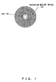
- Fig. 1 explains a CD to which a tag is attached.
- the tag 100 is attached to the proximity of the center of the CD, and a recording medium (metal portion) 101 exists outside the tag.
- Fig. 2 explains a conventional example of a reading system, for example, in a case where many CDs are stacked.
- a method for reading contents of a tag by connecting a high-gain antenna 107 to an RFID reader/writer system 106, and by making the antenna 107 close to the CD is used if contents of tags are read from many CDs to which RFID tags are attached.
- This method has a problem that the number of CDs from which data of tags can be accurately read becomes small among the stacked many CDs as described above.
- Patent Document 1 discloses a technique, for example, using a pillar-shaped of coiled insulator based material antenna having a height direction that is an insertion direction into a cylinder in order to communicate with a non-contact data carrier installed on the inner surface of the cylinder.
- Patent Document 2 discloses an information protection management system for recording a decryption key to an RFID chip of a recording medium on which encrypted information is recorded, and for decrypting the encrypted information by using the decryption key read from the RFID chip when the encrypted information is read from the medium.
- An object of the present invention is to enable contents of electronic tags attached to many disks such as CDs, DVDs, etc. to be accurately read by reducing an influence of a recording medium (metal portion) of a CD or a DVD.
- a disk tag reading device is a device for reading contents of an electronic tag attached to a disk.
- a holder which is inserted into the central hole of the disk configures an antenna for communicating with the electronic tag attached to the disk.
- FIG. 3 explains the principle of a disk tag reading device according to the present invention.
- This figure shows a device for reading contents of an electronic tag, for example, an RFID attached to a disk such as a CD, a DVD, etc.
- a holder 2 which is inserted into the central hole of the disk such as a CD 1, configures an antenna for communicating with the electronic tag attached to the disk.
- This device may also comprise a reader/writer for reading, by way of example, within a base 3 of the holder 2.
- a connector that can be connected by being plugged in a connector arranged on the side of the base 3 of the holder 2 may be comprised as a connector connected to a coaxial cable connected to the antenna, or an antenna for communicating with the antenna provided on the side of the base 3 of the holder 2 may be comprised as the antenna connected to the coaxial cable.
- the holder 2 is a hollow pipe having a diameter smaller than the hole of the disk, comprises a slot having a length of a half wavelength of an electric wave for communicating with the tag in a direction parallel or oblique to the longitudinal direction of the hollow pipe, or in a spiral state, and can configure a slot antenna as the antenna.
- the holder 2 may further comprise a slit in the longitudinal direction of the hollow pipe in this case.
- a material of whole, an inner surface, or an outer surface of the holder 2 may be a conductor.
- the holder 2 may be the above described hollow pipe, may have a plurality of open windows arranged in the longitudinal direction of the hollow pipe, can comprise a thin conductor in a position of the central axis of the hollow pipe, and can configure an electromagnetic wave leak antenna as the antenna.
- the holder 2 may have a slit in the longitudinal direction of the above described hollow pipe, dielectric discs having the same diameter as the inner diameter of the hollow pipe are installed at predetermined intervals within the hollow pipe, and the holder 2 can configure a billiotic grading cylinder slot antenna as the antenna.
- the holder 2 may comprise a slit in the longitudinal direction of the above described hollow pipe, may comprise a slot having a length of a half wavelength of an electric wave for communicating with the tag in the longitudinal direction of the hollow pipe, a dielectric film, to which conductive foil having a narrow width for communicating with the tag is pasted, is pasted to the inner or outer side of the hollow pipe so that part of the conductive foil aligns with part of the slot via the dielectric film, whereby a slot antenna can be configured as the antenna.
- a holder which is inserted into the central hole of a disk is used as an antenna for communicating with a tag attached to the disk such as a CD, a DVD, etc., whereby contents of the electronic tag attached to the disk can be accurately read even if many disks are stacked.
- Figs. 4 to 6 explain a disk tag reading device using a holder which is inserted into a hole of a disk such as a CD, a DVD, etc., as a slot antenna. Similar to Fig. 3, the holder 2 into which a CD, etc. is inserted is used as an antenna, which is connected by cable or radio to a reader/writer comprised within a base 3.
- a linear slot 10 is notched in parallel to the longitudinal direction of the holder, so that a slot antenna is formed as an antenna.
- This slot is assumed to be, for example, a linear slot having a length of an approximately half wavelength of an electric wave for communicating with a tag of a CD.
- the slot antenna shown in Fig. 4 is formed by pasting copper foil, on which a slot is notched in the longitudinal direction, to a round bar of, for example, Teflon (registered trademark).
- Teflon registered trademark
- the length of the antenna is 260 mm, its diameter is 12 mm, and the central frequency of an electric wave used is 915 MHz.
- a wavelength ⁇ in a vacuum is approximately 328 mm
- the relative dielectric constant of Teflon (registered trademark) is 2.2.
- ⁇ g /2 111 mm (a calculation value of the length of the slot).
- the length of the slot can be, for example, approximately 120 mm in correspondence, for example, with impedance matching.
- the slot 10 is notched at a relatively small angle obliquely to the longitudinal direction of the holder 2, so that a slot antenna is similarly configured.
- This slot antenna is effective for reading a tag, for example, even in a state where a CD, etc. is obliquely inserted into the holder 2.
- a slot 10 is configured by being cut in a spiral state in the longitudinal direction of the holder 2.
- the slot that forms a considerably large angle in the longitudinal direction of the holder 2 is cut, for example, on a flat board before a hollow cylinder is formed, and the disc is rolled within the hollow cylinder, whereby the slot in the spiral state is formed.
- Fig. 7 explains a method supplying power, for example, to the slot antenna shown in Fig. 4.
- the holder 2 is entirely a metal pipe, or a pipe having an outer or inner surface around which an electric conductor such as metal foil, etc. is wound.
- the core wire and the shield of a coaxial cable 15 are connected to the bottom of the slot 10, and the coaxial cable 15 is connected by a coaxial connector 16 to a reader/writer system within a base 3 of the holder 2.
- Fig. 8 explains a plug-in connection between a connector on the side of the holder, which is connected to the reader/writer antenna, and the connector on the side of the reader/writer within the base 3.
- the coaxial connector 16 which is explained with reference to Fig. 7 and connected to the coaxial cable 15 on the side of the holder, is plugged in the connector 18 arranged on the side of the base 3, and connected to a personal computer 22 via a coaxial cable 19 on the side of the base 3, a transmission/reception circuit 20, a control circuit 21, etc., so that tags of, for example, many CDs, DVDs, etc. are collectively read.
- Fig. 9 shows a configuration example of a collective tag reading system that comprises patch antennas on the sides of the holder 2 and the base 3 in addition to the connectors for the connection on the side of the base 3, and can switch between a connection via the connectors and a wireless connection using the patch antennas.
- the connectors 16 and 18 are provided, for example, further outer than in Fig. 8.
- the patch antennas 26 and 27 are respectively provided on the side of the holder 2 and the side of the base 3. Additionally, an RF switch 25 for switching a connection between the coaxial cable 15 and the connector 16 or the patch antenna 26 is comprised.
- an RF switch 30 for switching a connection between the coaxial cable 28 connected to the patch antenna 27 or the coaxial cable 19 connected to the connector 18 and an input/output circuit 31 is similarly comprised.
- Read data is given to the personal computer 22 via the RF switch 30, the input/output circuit 31, and the control circuit 32.
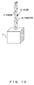
- Figs. 10 and 11 explain an example where an antenna in a form other than the above described normal slot antenna is arranged as a holder.
- the holder 35 is a hollow pipe that is thinner than the central hole of a CD, a DVD, etc., and its whole is a conductor such as a metal, etc., or the holder 35 is a pipe having an outer or inner surface to which metal foil is pasted.
- a thin conductor 36 is comprised in a position of the central axis of the hollow pipe. Additionally, many open windows 37 are provided generally to form a small angle with the longitudinal direction of the hollow conductor, so that an electromagnetic wave leak antenna is formed as a whole.
- the thin conductor 36 on the central axis is set so that characteristic impedance between the hollow pipe and the conductor 36 matches the characteristic impedance of the coaxial cable connected. This electromagnetic leak antenna is disclosed by the following document.
- Non-Patent Document 1 K. Fujimoto, J. R. James “Mobile Antenna Systems Handbook, pp. 345-351, Artech House Publishers, Boston/London (1994)
- Fig. 11 shows a configuration of a billiotic grading cylinder slot antenna as another antenna form.
- a holder 40 is a hollow metal pipe thinner than a hole of a disk, or a pipe having an outer or inner surface to which metal foil is pasted.
- the metal pipe does not form a full circle, namely, the metal pipe has a slit in its entirety, and dielectric discs, namely, dielectric discs having a diameter almost equal to the inner diameter of the hollow pipe are installed at predetermined intervals within the pipe, whereby a billiotic grading cylinder slot antenna is formed.
- dielectric discs namely, dielectric discs having a diameter almost equal to the inner diameter of the hollow pipe are installed at predetermined intervals within the pipe, whereby a billiotic grading cylinder slot antenna is formed.
- Non-Patent Document 2 A. I. Nosich and V. P. Shestopalov, "Waveguide Properties of Open Metalized Dielectric Transmission Lines of the Cylindrical Type", Radio Engn. Electronic Physics (Eng1. trans1.), vol. 24, pp. 1-9, Scripta Publ. (1980)
- a configuration example of a slot antenna for facilitating its manufacturing is explained last with reference to Fig. 12.
- This antenna is a slot antenna as a whole.
- a holder 50 is, for example, a hollow cylinder having a slit that does not form a full circle, and a slot 51 having a length of approximately a half wavelength is notched in the longitudinal direction of the hollow pipe.
- the input impedance of the antenna can be reduced, and becomes easy to match the coaxial cable of a characteristic impedance of 50 ⁇ .
- the core wire and the shield of the coaxial connector are connected to the bottom of the slot. Generally, their connection method is soldering.
- a 50- ⁇ micro-strip line is used instead of the coaxial cable in Fig. 12.
- the micro-strip line is composed of a line formed by a conductive film, a film-state dielectric material, and a conductor of the antenna. The width of the line is determined so that the characteristic impedance becomes 50 ⁇ .
- the micro-strip line is connected to the core wire of the coaxial connector.
- the ground of the coaxial connector is connected to the conductor of the antenna.
- conductor foil 53 having a narrow width is pasted to a dielectric board 52 that is relatively soft in a film state as shown in Fig. 12, and the dielectric board 52 is pasted to the outside or inside of the hollow pipe so that the conductive foil 53 does not directly contact the metal pipe, namely, the conductive foil 53 is positioned in a lower position of the slot 51 via the film-state dielectric board 52.
- a position in which the film-state dielectric board 52 is pasted is adjusted to make the impedance matching with the impedance 50 ⁇ of the coaxial cable on the side of the reader/writer system (base 3) connected to the coaxial connector 54, whereby the adjustment of the impedance matching becomes easier than the connection of the coaxial cable 15 to a suitable position of the slot 10 as explained with reference to Fig. 7.
- the coaxial connector 54 is plugged, for example, in the connector shown in Fig. 8, whereby a connection to the side of the reader/writer is made.
- a holder of a disk is used as an antenna, whereby accurate reading can be made even if disks (20 disks or more) are stacked by the length of a slot, for example, in contrast with a case where contents of tags of only a few disks can be read with the system according to the conventional technique shown in Fig. 2.
Landscapes
- Engineering & Computer Science (AREA)
- Physics & Mathematics (AREA)
- General Physics & Mathematics (AREA)
- Theoretical Computer Science (AREA)
- Toxicology (AREA)
- Health & Medical Sciences (AREA)
- Microelectronics & Electronic Packaging (AREA)
- Computer Networks & Wireless Communication (AREA)
- Computer Hardware Design (AREA)
- Electromagnetism (AREA)
- General Health & Medical Sciences (AREA)
- Artificial Intelligence (AREA)
- Computer Vision & Pattern Recognition (AREA)
- Waveguide Aerials (AREA)
- Optical Record Carriers And Manufacture Thereof (AREA)
- Details Of Aerials (AREA)
- Automatic Analysis And Handling Materials Therefor (AREA)
Abstract
Description
- The present invention relates to a system method for reading an electronic tag such as an RFID, etc., and more particularly, to a disk tag reading device for reading contents of a tag attached to a disk such as a CD, a DVD, etc.
- In recent years, attention has been paid to an RFID (Radio Frequency Identification) system as a system for managing parts or an inventory. For example, if the production or distribution of CDs, DVDs, etc., tags of as many stacked CDs or DVDs as possible must be collectively read. However, if many CDs or DVDs are stacked, there is a problem that the number of readable CDs or DVDs is reduced due to an influence of a recording medium (metal portion) of a CD or a DVD.
- Fig. 1 explains a CD to which a tag is attached. The
tag 100 is attached to the proximity of the center of the CD, and a recording medium (metal portion) 101 exists outside the tag. - Fig. 2 explains a conventional example of a reading system, for example, in a case where many CDs are stacked. In this figure, a method for reading contents of a tag by connecting a high-
gain antenna 107 to an RFID reader/writer system 106, and by making theantenna 107 close to the CD is used if contents of tags are read from many CDs to which RFID tags are attached. This method, however, has a problem that the number of CDs from which data of tags can be accurately read becomes small among the stacked many CDs as described above. - The following documents exist as conventional techniques for such a system for reading a tag, etc.
- [Patent Document 1] Japanese Patent Publication No. 2001-357366 "Antenna Device and Reader/Writer Device"
- [Patent Document 2] Japanese Patent Publication No. 2003-69549 "Information Protection Management System Using a Recording Medium Equipped with an RFID"
-
Patent Document 1 discloses a technique, for example, using a pillar-shaped of coiled insulator based material antenna having a height direction that is an insertion direction into a cylinder in order to communicate with a non-contact data carrier installed on the inner surface of the cylinder. -
Patent Document 2 discloses an information protection management system for recording a decryption key to an RFID chip of a recording medium on which encrypted information is recorded, and for decrypting the encrypted information by using the decryption key read from the RFID chip when the encrypted information is read from the medium. - These techniques, however, cannot solve the problem that contents of tags attached to disks cannot be accurately read when many disks such as CDs, DVDs, etc. are stacked.
- An object of the present invention is to enable contents of electronic tags attached to many disks such as CDs, DVDs, etc. to be accurately read by reducing an influence of a recording medium (metal portion) of a CD or a DVD.
- A disk tag reading device according to the present invention is a device for reading contents of an electronic tag attached to a disk. A holder which is inserted into the central hole of the disk configures an antenna for communicating with the electronic tag attached to the disk.
-
- Fig. 1 explains a CD to which a tag is attached;
- Fig. 2 explains a conventional example of a tag reading system;
- Fig. 3 explains an example of a principle configuration of a disk tag reading device according to the present invention;
- Fig. 4 explains a configuration example (No. 1) of a slot antenna for reading a disk tag;
- Fig. 5 explains a configuration example (No. 2) of a slot antenna for reading a disk tag;
- Fig. 6 explains a configuration example (No. 3) of a slot antenna for reading a disk tag;
- Fig. 7 explains a method for supplying power to a slot antenna;
- Fig. 8 shows a configuration example of a tag reading device using a plug-in connection of a connector;
- Fig. 9 shows a configuration example of a tag reading device for switching between a plug-in connection of a connector and a wireless connection;
- Fig. 10 explains an electromagnetic wave leak antenna for reading a disk tag;
- Fig. 11 shows a configuration example of a billiotic grading cylinder slot antenna for reading a disk tag; and
- Fig. 12 explains a configuration example of a slot antenna for facilitating manufacturing.
- Fig. 3 explains the principle of a disk tag reading device according to the present invention. This figure shows a device for reading contents of an electronic tag, for example, an RFID attached to a disk such as a CD, a DVD, etc. A
holder 2 which is inserted into the central hole of the disk such as aCD 1, configures an antenna for communicating with the electronic tag attached to the disk. This device may also comprise a reader/writer for reading, by way of example, within abase 3 of theholder 2. - In a preferred embodiment according to the present invention, a connector that can be connected by being plugged in a connector arranged on the side of the
base 3 of theholder 2 may be comprised as a connector connected to a coaxial cable connected to the antenna, or an antenna for communicating with the antenna provided on the side of thebase 3 of theholder 2 may be comprised as the antenna connected to the coaxial cable. - Additionally, in the preferred embodiment, the
holder 2 is a hollow pipe having a diameter smaller than the hole of the disk, comprises a slot having a length of a half wavelength of an electric wave for communicating with the tag in a direction parallel or oblique to the longitudinal direction of the hollow pipe, or in a spiral state, and can configure a slot antenna as the antenna. Or, theholder 2 may further comprise a slit in the longitudinal direction of the hollow pipe in this case. Besides, a material of whole, an inner surface, or an outer surface of theholder 2 may be a conductor. - Furthermore, in the preferred embodiment, the
holder 2 may be the above described hollow pipe, may have a plurality of open windows arranged in the longitudinal direction of the hollow pipe, can comprise a thin conductor in a position of the central axis of the hollow pipe, and can configure an electromagnetic wave leak antenna as the antenna. - Still further, in the preferred embodiment, the
holder 2 may have a slit in the longitudinal direction of the above described hollow pipe, dielectric discs having the same diameter as the inner diameter of the hollow pipe are installed at predetermined intervals within the hollow pipe, and theholder 2 can configure a billiotic grading cylinder slot antenna as the antenna. - Still further, in the preferred embodiment, the
holder 2 may comprise a slit in the longitudinal direction of the above described hollow pipe, may comprise a slot having a length of a half wavelength of an electric wave for communicating with the tag in the longitudinal direction of the hollow pipe, a dielectric film, to which conductive foil having a narrow width for communicating with the tag is pasted, is pasted to the inner or outer side of the hollow pipe so that part of the conductive foil aligns with part of the slot via the dielectric film, whereby a slot antenna can be configured as the antenna. - According to the present invention, a holder which is inserted into the central hole of a disk is used as an antenna for communicating with a tag attached to the disk such as a CD, a DVD, etc., whereby contents of the electronic tag attached to the disk can be accurately read even if many disks are stacked.
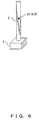
- Figs. 4 to 6 explain a disk tag reading device using a holder which is inserted into a hole of a disk such as a CD, a DVD, etc., as a slot antenna. Similar to Fig. 3, the
holder 2 into which a CD, etc. is inserted is used as an antenna, which is connected by cable or radio to a reader/writer comprised within abase 3. In Fig. 4, alinear slot 10 is notched in parallel to the longitudinal direction of the holder, so that a slot antenna is formed as an antenna. This slot is assumed to be, for example, a linear slot having a length of an approximately half wavelength of an electric wave for communicating with a tag of a CD. - The slot antenna shown in Fig. 4 is formed by pasting copper foil, on which a slot is notched in the longitudinal direction, to a round bar of, for example, Teflon (registered trademark). Assume that the length of the antenna is 260 mm, its diameter is 12 mm, and the central frequency of an electric wave used is 915 MHz. Also assume that a wavelength λ in a vacuum is approximately 328 mm, the relative dielectric constant of Teflon (registered trademark) is 2.2. In this case, λg =λ/√εr = 222 mm, and λg/2=111 mm (a calculation value of the length of the slot). However, the length of the slot can be, for example, approximately 120 mm in correspondence, for example, with impedance matching.
- In Fig. 5, the
slot 10 is notched at a relatively small angle obliquely to the longitudinal direction of theholder 2, so that a slot antenna is similarly configured. This slot antenna is effective for reading a tag, for example, even in a state where a CD, etc. is obliquely inserted into theholder 2. - In Fig. 6, a
slot 10 is configured by being cut in a spiral state in the longitudinal direction of theholder 2. For example, the slot that forms a considerably large angle in the longitudinal direction of theholder 2 is cut, for example, on a flat board before a hollow cylinder is formed, and the disc is rolled within the hollow cylinder, whereby the slot in the spiral state is formed. - Fig. 7 explains a method supplying power, for example, to the slot antenna shown in Fig. 4. In this figure, the
holder 2 is entirely a metal pipe, or a pipe having an outer or inner surface around which an electric conductor such as metal foil, etc. is wound. Additionally, the core wire and the shield of acoaxial cable 15 are connected to the bottom of theslot 10, and thecoaxial cable 15 is connected by acoaxial connector 16 to a reader/writer system within abase 3 of theholder 2. - Fig. 8 explains a plug-in connection between a connector on the side of the holder, which is connected to the reader/writer antenna, and the connector on the side of the reader/writer within the
base 3. In this figure, thecoaxial connector 16, which is explained with reference to Fig. 7 and connected to thecoaxial cable 15 on the side of the holder, is plugged in theconnector 18 arranged on the side of thebase 3, and connected to apersonal computer 22 via acoaxial cable 19 on the side of thebase 3, a transmission/reception circuit 20, acontrol circuit 21, etc., so that tags of, for example, many CDs, DVDs, etc. are collectively read. - Fig. 9 shows a configuration example of a collective tag reading system that comprises patch antennas on the sides of the
holder 2 and thebase 3 in addition to the connectors for the connection on the side of thebase 3, and can switch between a connection via the connectors and a wireless connection using the patch antennas. In this figure, theconnectors patch antennas holder 2 and the side of thebase 3. Additionally, anRF switch 25 for switching a connection between thecoaxial cable 15 and theconnector 16 or thepatch antenna 26 is comprised. In the meantime, anRF switch 30 for switching a connection between thecoaxial cable 28 connected to thepatch antenna 27 or thecoaxial cable 19 connected to theconnector 18 and an input/output circuit 31 is similarly comprised. Read data is given to thepersonal computer 22 via theRF switch 30, the input/output circuit 31, and thecontrol circuit 32. - Figs. 10 and 11 explain an example where an antenna in a form other than the above described normal slot antenna is arranged as a holder. In Fig. 10, the
holder 35 is a hollow pipe that is thinner than the central hole of a CD, a DVD, etc., and its whole is a conductor such as a metal, etc., or theholder 35 is a pipe having an outer or inner surface to which metal foil is pasted. In Fig. 10, athin conductor 36 is comprised in a position of the central axis of the hollow pipe. Additionally, manyopen windows 37 are provided generally to form a small angle with the longitudinal direction of the hollow conductor, so that an electromagnetic wave leak antenna is formed as a whole. Generally, thethin conductor 36 on the central axis is set so that characteristic impedance between the hollow pipe and theconductor 36 matches the characteristic impedance of the coaxial cable connected. This electromagnetic leak antenna is disclosed by the following document. - [Non-Patent Document 1] K. Fujimoto, J. R. James "Mobile Antenna Systems Handbook, pp. 345-351, Artech House Publishers, Boston/London (1994)
- Fig. 11 shows a configuration of a billiotic grading cylinder slot antenna as another antenna form. Also in this figure, a
holder 40 is a hollow metal pipe thinner than a hole of a disk, or a pipe having an outer or inner surface to which metal foil is pasted. For example, the metal pipe does not form a full circle, namely, the metal pipe has a slit in its entirety, and dielectric discs, namely, dielectric discs having a diameter almost equal to the inner diameter of the hollow pipe are installed at predetermined intervals within the pipe, whereby a billiotic grading cylinder slot antenna is formed. The following document discloses this billiotic grading cylinder slot antenna. - [Non-Patent Document 2] A. I. Nosich and V. P. Shestopalov, "Waveguide Properties of Open Metalized Dielectric Transmission Lines of the Cylindrical Type", Radio Engn. Electronic Physics (Eng1. trans1.), vol. 24, pp. 1-9, Scripta Publ. (1980)
- A configuration example of a slot antenna for facilitating its manufacturing is explained last with reference to Fig. 12. This antenna is a slot antenna as a whole. A
holder 50 is, for example, a hollow cylinder having a slit that does not form a full circle, and aslot 51 having a length of approximately a half wavelength is notched in the longitudinal direction of the hollow pipe. By providing the slit, the input impedance of the antenna can be reduced, and becomes easy to match the coaxial cable of a characteristic impedance of 50 Ω. In Fig. 7, the core wire and the shield of the coaxial connector are connected to the bottom of the slot. Generally, their connection method is soldering. Since it is very difficult to connect the core wire and the shield of the coaxial cable in a position where the characteristic impedance becomes 50 Q to make the impedance matching. Therefore, a 50-Ω micro-strip line is used instead of the coaxial cable in Fig. 12. The micro-strip line is composed of a line formed by a conductive film, a film-state dielectric material, and a conductor of the antenna. The width of the line is determined so that the characteristic impedance becomes 50 Ω. The micro-strip line is connected to the core wire of the coaxial connector. The ground of the coaxial connector is connected to the conductor of the antenna. - Namely,
conductor foil 53 having a narrow width is pasted to adielectric board 52 that is relatively soft in a film state as shown in Fig. 12, and thedielectric board 52 is pasted to the outside or inside of the hollow pipe so that theconductive foil 53 does not directly contact the metal pipe, namely, theconductive foil 53 is positioned in a lower position of theslot 51 via the film-state dielectric board 52. A position in which the film-state dielectric board 52 is pasted is adjusted to make the impedance matching with theimpedance 50 Ω of the coaxial cable on the side of the reader/writer system (base 3) connected to thecoaxial connector 54, whereby the adjustment of the impedance matching becomes easier than the connection of thecoaxial cable 15 to a suitable position of theslot 10 as explained with reference to Fig. 7. Thecoaxial connector 54 is plugged, for example, in the connector shown in Fig. 8, whereby a connection to the side of the reader/writer is made. - As described above, according to the present invention, a holder of a disk is used as an antenna, whereby accurate reading can be made even if disks (20 disks or more) are stacked by the length of a slot, for example, in contrast with a case where contents of tags of only a few disks can be read with the system according to the conventional technique shown in Fig. 2.
- Additionally, the above provided explanation refers to the usage of a holder as an antenna by mainly focusing on a data read of tags. However, this antenna is also available as a data write of tags as a matter of course.
Claims (10)
- A disk tag reading device for reading contents of an electronic tag attached to a disk (1), wherein
a holder (2) which is inserted into a central hole of the disk (1) configures an antenna for communicating with the electronic tag attached to the disk (1). - The disk tag reading device according to claim 1, further comprising
a connector (16), which is connected to an opposite side of a coaxial cable (15) connected to the antenna (2), and can be connected by being plugged in a connector (18) arranged on a side of a base (3) of the holder. - The disk tag reading device according to claim 1, further comprising
an antenna (2), which is connected to an opposite side of a coaxial cable (15) connected to the antenna, for communicating with an antenna comprised on a side of a base (3) of the holder. - The disk tag reading device according to claim 1, wherein:the holder (2) is a hollow pipe having an outside diameter smaller than the hole of the disk, and a whole, an inner or outer surface that is a conductor; andthe holder comprises a slot (10) having a length of a half wavelength of an electric wave for communicating with the tag in parallel to a longitudinal direction of the hollow pipe, and configures a slot antenna as the antenna.
- The disk tag reading device according to claim 1, wherein:the holder (2) is a hollow pipe having an outside diameter smaller than the hole of the disk, and a whole, an inner or outer surface that is a conductor; andthe holder comprises a slot (10) having a length of a half wavelength of an electric wave for communicating with the tag in a direction obliquely to a longitudinal direction of the hollow pipe, and configures a slot antenna as the antenna.
- The disk tag reading device according to claim 1, wherein:the holder (2) is a hollow pipe having an outside diameter smaller than the hole of the disk, and a whole, an inner or outer surface that is a conductor; andthe holder comprises a slot (10) having a length of a half wavelength of an electric wave for communicating with the tag in a spiral state in a longitudinal direction of the hollow pipe, and configures a slot antenna as the antenna.
- The disk tag reading device according to claim 1, wherein:the holder is a hollow pipe having an outside diameter smaller than the hole of the disk, and a whole, an inner or outer surface that is a conductor; andthe holder comprises a slit at least in a longitudinal direction of a conductor portion of the hollow pipe, comprises a slot having a length of a half wavelength of an electric wave for communicating with the tag in the longitudinal direction of the hollow pipe, and configures a slot antenna as the antenna.
- The disk tag reading device according to claim 1, wherein:the holder (35) is a hollow pipe having an outside diameter smaller than the hole of the disk, and a whole, an inner or outer surface that is a conductor;the holder comprises a plurality of open windows (37) provided in a longitudinal direction of the hollow pipe; andthe holder further comprises a thin conductor in a position of a central axis of the hollow pipe, so that an electromagnetic wave leak antenna is configured as the antenna.
- The disk tag reading device according to claim 1, wherein:the holder (40) is a hollow pipe having an outside diameter smaller than the hole of the disk, and a whole, an inner or outer surface that is a conductor;the holder comprises a slit (41) at least in a longitudinal direction of a conductor portion of the hollow pipe; anddielectric discs having a same diameter as an inner diameter of the hollow pipe are installed at predetermined intervals within the hollow pipe, so that a billiotic grating cylinder slot antenna is configured as the antenna.
- The disk tag reading device according to claim 1, wherein:the holder is a hollow pipe having an outside diameter smaller than the hole of the disk:the holder comprises a slit in a longitudinal direction of the hollow pipe, and a slot having a length of a half wavelength of an electric wave for communicating with the tag in parallel to the longitudinal direction of the hollow pipe; anda dielectric film, to which conductive foil having a narrow width for connecting the antenna to a reader/writer of the tag is pasted, is pasted to an inside or outside of the hollow pipe so that part of the conductive foil aligns with part of the slot via the dielectric film, and a slot antenna is configured as the antenna.
Applications Claiming Priority (1)
| Application Number | Priority Date | Filing Date | Title |
|---|---|---|---|
| JP2004219222A JP2006039967A (en) | 2004-07-27 | 2004-07-27 | Disc tag reader |
Publications (2)
| Publication Number | Publication Date |
|---|---|
| EP1622063A2 true EP1622063A2 (en) | 2006-02-01 |
| EP1622063A3 EP1622063A3 (en) | 2008-10-01 |
Family
ID=35170060
Family Applications (1)
| Application Number | Title | Priority Date | Filing Date |
|---|---|---|---|
| EP04030486A Withdrawn EP1622063A3 (en) | 2004-07-27 | 2004-12-22 | Device for reading contents of an electronic tag attached to a disk |
Country Status (3)
| Country | Link |
|---|---|
| US (1) | US7378970B2 (en) |
| EP (1) | EP1622063A3 (en) |
| JP (1) | JP2006039967A (en) |
Families Citing this family (10)
| Publication number | Priority date | Publication date | Assignee | Title |
|---|---|---|---|---|
| US7398926B1 (en) * | 2003-10-06 | 2008-07-15 | Applied Wireless Identifications Group, Inc. | Apparatus and method for programming an RFID transponder using a constrained field |
| US7256698B2 (en) * | 2005-02-23 | 2007-08-14 | Prorit Corporation | Spindle with an RFID function |
| JP4208254B2 (en) * | 2006-05-31 | 2009-01-14 | サンコール株式会社 | Antenna unit, wireless communication structure, and antenna structure |
| JP4560017B2 (en) * | 2006-08-03 | 2010-10-13 | 株式会社日立製作所 | Disc media and method for producing disc media |
| JP4234167B2 (en) | 2006-10-23 | 2009-03-04 | インターナショナル・ビジネス・マシーンズ・コーポレーション | Article storage case with RFID tag and RFID system |
| EP2226746B1 (en) | 2007-11-28 | 2012-01-11 | Fujitsu Limited | Metallic pipe managed by wireless ic tag, and the wireless ic tag |
| JP4896922B2 (en) * | 2008-05-01 | 2012-03-14 | 富士通株式会社 | Radio tag and conductive pipe having radio tag |
| JP2012169777A (en) * | 2011-02-10 | 2012-09-06 | Sony Corp | Information processor, information processing method, and program |
| ES2832755T3 (en) | 2017-03-01 | 2021-06-11 | Signify Holding Bv | Illumination device with slot antenna |
| CN110890623B (en) * | 2019-11-14 | 2025-08-05 | 广东通宇通讯股份有限公司 | Antenna vibrator with filtering function, filtering radiation unit and antenna |
Citations (3)
| Publication number | Priority date | Publication date | Assignee | Title |
|---|---|---|---|---|
| US5955997A (en) | 1996-05-03 | 1999-09-21 | Garmin Corporation | Microstrip-fed cylindrical slot antenna |
| FR2790346A1 (en) | 1999-02-26 | 2000-09-01 | Schlumberger Systems & Service | DEVICE AND METHOD FOR SECURING A DATA STORAGE MEDIA |
| EP1617506A2 (en) | 2004-07-13 | 2006-01-18 | Fujitsu Limited | Radio tag antenna structure for an optical recording medium and a case for an optical recording medium with a radio tag antenna |
Family Cites Families (11)
| Publication number | Priority date | Publication date | Assignee | Title |
|---|---|---|---|---|
| JPH02230584A (en) * | 1989-03-02 | 1990-09-12 | Seiko Epson Corp | compact disc |
| US5604485A (en) * | 1993-04-21 | 1997-02-18 | Motorola Inc. | RF identification tag configurations and assemblies |
| US5669494A (en) * | 1994-08-11 | 1997-09-23 | Full Circle Company | Storage carousel for compact disks and the like |
| DE69720938T2 (en) * | 1996-12-20 | 2004-03-04 | Texas Instruments Inc., Dallas | Security system improvements |
| US6344833B1 (en) * | 1999-04-02 | 2002-02-05 | Qualcomm Inc. | Adjusted directivity dielectric resonator antenna |
| SE516359C2 (en) * | 1999-04-26 | 2002-01-08 | Smarteq Wireless | Antenna for mobile radio communication device, has conductive structure extending between feed portion and opposite edges forming an opening radiating slit |
| US8050964B2 (en) * | 1999-05-06 | 2011-11-01 | Etagz, Inc. | Computer-readable medium product label apparatus and method |
| JP4592876B2 (en) | 2000-06-14 | 2010-12-08 | 大日本印刷株式会社 | Antenna device and reader / writer device |
| CN1520628A (en) * | 2001-06-27 | 2004-08-11 | 株式会社Emw天线 | Antenna for portable radio communication equipment |
| JP2003069549A (en) | 2001-08-23 | 2003-03-07 | Hirano Design Sekkei:Kk | Information protection management system using rfid mounted storage medium |
| US7256698B2 (en) * | 2005-02-23 | 2007-08-14 | Prorit Corporation | Spindle with an RFID function |
-
2004
- 2004-07-27 JP JP2004219222A patent/JP2006039967A/en active Pending
- 2004-12-01 US US11/001,507 patent/US7378970B2/en not_active Expired - Fee Related
- 2004-12-22 EP EP04030486A patent/EP1622063A3/en not_active Withdrawn
Patent Citations (3)
| Publication number | Priority date | Publication date | Assignee | Title |
|---|---|---|---|---|
| US5955997A (en) | 1996-05-03 | 1999-09-21 | Garmin Corporation | Microstrip-fed cylindrical slot antenna |
| FR2790346A1 (en) | 1999-02-26 | 2000-09-01 | Schlumberger Systems & Service | DEVICE AND METHOD FOR SECURING A DATA STORAGE MEDIA |
| EP1617506A2 (en) | 2004-07-13 | 2006-01-18 | Fujitsu Limited | Radio tag antenna structure for an optical recording medium and a case for an optical recording medium with a radio tag antenna |
Also Published As
| Publication number | Publication date |
|---|---|
| US20060023575A1 (en) | 2006-02-02 |
| JP2006039967A (en) | 2006-02-09 |
| US7378970B2 (en) | 2008-05-27 |
| EP1622063A3 (en) | 2008-10-01 |
Similar Documents
| Publication | Publication Date | Title |
|---|---|---|
| US8077115B2 (en) | Antenna device, radio tag reader and article management system | |
| EP1617506B1 (en) | Radio tag antenna structure for an optical recording medium | |
| JP5337834B2 (en) | RFID tag and RFID communication system | |
| US8081541B2 (en) | Optical disc | |
| US7696884B2 (en) | Systems and methods for enhancing the magnetic coupling in a wireless communication system | |
| US20060232419A1 (en) | RFID tag and antenna arranging method | |
| US20080246616A1 (en) | Media case and circuit pattern sheet | |
| US7378970B2 (en) | Disk tag reading device | |
| US20080036606A1 (en) | Commodity managing antenna and control method of the same | |
| CN110945716B (en) | Patch antenna for coupling transmit/receive terminals to RFID devices | |
| CN103703473A (en) | Electronic equipment | |
| JP2009130446A (en) | Wireless transmission / reception device, non-contact information recording medium, information reading / writing device, and management system | |
| CN104067444A (en) | Small broadband loop antenna for near-field applications | |
| Zuffanelli et al. | On‐metal UHF‐RFID passive tags based on complementary split‐ring resonators | |
| CN102509872A (en) | UHF (ultra high frequency) RFID (radio frequency identification device) electronic label antenna | |
| US9088066B2 (en) | Antenna for an NFC device | |
| US7378972B2 (en) | RFID tag | |
| CN110659715A (en) | A UHF helical antenna dielectric label | |
| B. Abdallah et al. | Analysis, design, and measurements of an ultrasmall on‐metal UHF RFID tag antenna | |
| JP5720271B2 (en) | Case for optical recording medium, boost antenna, and management system | |
| JP2004086683A (en) | Rf tag | |
| CN201117815Y (en) | Low cost broad band small volume high gain linear polarization antenna | |
| KR101111891B1 (en) | Non-Contact Label with Y-Shaped Omnidirectional Antenna | |
| JP5594178B2 (en) | Communications system | |
| CN103164733B (en) | A kind of Electronic Tag Structure with selective recognition function |
Legal Events
| Date | Code | Title | Description |
|---|---|---|---|
| PUAI | Public reference made under article 153(3) epc to a published international application that has entered the european phase |
Free format text: ORIGINAL CODE: 0009012 |
|
| AK | Designated contracting states |
Kind code of ref document: A2 Designated state(s): AT BE BG CH CY CZ DE DK EE ES FI FR GB GR HU IE IS IT LI LT LU MC NL PL PT RO SE SI SK TR |
|
| AX | Request for extension of the european patent |
Extension state: AL BA HR LV MK YU |
|
| PUAL | Search report despatched |
Free format text: ORIGINAL CODE: 0009013 |
|
| AK | Designated contracting states |
Kind code of ref document: A3 Designated state(s): AT BE BG CH CY CZ DE DK EE ES FI FR GB GR HU IE IS IT LI LT LU MC NL PL PT RO SE SI SK TR |
|
| AX | Request for extension of the european patent |
Extension state: AL BA HR LV MK YU |
|
| 17P | Request for examination filed |
Effective date: 20080925 |
|
| 17Q | First examination report despatched |
Effective date: 20081103 |
|
| AKX | Designation fees paid |
Designated state(s): DE FR GB |
|
| STAA | Information on the status of an ep patent application or granted ep patent |
Free format text: STATUS: THE APPLICATION IS DEEMED TO BE WITHDRAWN |
|
| 18D | Application deemed to be withdrawn |
Effective date: 20100615 |