EP1621817B1 - Afterburner with assured ignition - Google Patents
Afterburner with assured ignition Download PDFInfo
- Publication number
- EP1621817B1 EP1621817B1 EP05291480A EP05291480A EP1621817B1 EP 1621817 B1 EP1621817 B1 EP 1621817B1 EP 05291480 A EP05291480 A EP 05291480A EP 05291480 A EP05291480 A EP 05291480A EP 1621817 B1 EP1621817 B1 EP 1621817B1
- Authority
- EP
- European Patent Office
- Prior art keywords
- burner
- injector
- fuel
- spark plug
- chamber
- Prior art date
- Legal status (The legal status is an assumption and is not a legal conclusion. Google has not performed a legal analysis and makes no representation as to the accuracy of the status listed.)
- Active
Links
- 239000000446 fuel Substances 0.000 claims description 27
- 230000001681 protective effect Effects 0.000 claims description 10
- 238000005507 spraying Methods 0.000 claims description 5
- 238000002347 injection Methods 0.000 claims description 4
- 239000007924 injection Substances 0.000 claims description 4
- 238000009423 ventilation Methods 0.000 claims description 4
- 238000002485 combustion reaction Methods 0.000 description 25
- 239000007921 spray Substances 0.000 description 6
- 239000007789 gas Substances 0.000 description 3
- 238000001816 cooling Methods 0.000 description 2
- 230000004907 flux Effects 0.000 description 2
- 238000011144 upstream manufacturing Methods 0.000 description 2
- 229930091051 Arenine Natural products 0.000 description 1
- 230000003471 anti-radiation Effects 0.000 description 1
- 239000010419 fine particle Substances 0.000 description 1
- 238000010438 heat treatment Methods 0.000 description 1
- 239000000203 mixture Substances 0.000 description 1
- 239000002245 particle Substances 0.000 description 1
- 230000001960 triggered effect Effects 0.000 description 1
- 238000009834 vaporization Methods 0.000 description 1
- 230000008016 vaporization Effects 0.000 description 1
Images


Classifications
-
- F—MECHANICAL ENGINEERING; LIGHTING; HEATING; WEAPONS; BLASTING
- F23—COMBUSTION APPARATUS; COMBUSTION PROCESSES
- F23R—GENERATING COMBUSTION PRODUCTS OF HIGH PRESSURE OR HIGH VELOCITY, e.g. GAS-TURBINE COMBUSTION CHAMBERS
- F23R3/00—Continuous combustion chambers using liquid or gaseous fuel
- F23R3/02—Continuous combustion chambers using liquid or gaseous fuel characterised by the air-flow or gas-flow configuration
- F23R3/16—Continuous combustion chambers using liquid or gaseous fuel characterised by the air-flow or gas-flow configuration with devices inside the flame tube or the combustion chamber to influence the air or gas flow
- F23R3/18—Flame stabilising means, e.g. flame holders for after-burners of jet-propulsion plants
- F23R3/20—Flame stabilising means, e.g. flame holders for after-burners of jet-propulsion plants incorporating fuel injection means
Definitions
- the invention relates to a turbojet afterburner chamber and relates more particularly to an improvement of the ignition system of said afterburner.
- Post-combustion is used in military aircraft to rapidly increase the engine thrust and consequently the speed of the aircraft when flight conditions require it.
- the US Patent 5,396,761 discloses a post combustion chamber comprising a plurality of radially extending burners, one of which is equipped with an ignition system comprising a candle associated with an injector.
- the latter has orifices oriented away from the spark plug so that ignition is not ensured for all operating conditions of the reactor.
- the U.S. Patent 3,931,707 discloses a post-combustion chamber equipped with a burner ring which has a plurality of nozzles delivering fuel upstream of a ring of fixed vanes where the fuel mixes with air entering the ring by a slot downstream. A candle can ignite this fuel. However, there is nothing to control the vaporization of the fuel so that the mixture ignites under all flight conditions.
- the invention applies to an adjacent type of combustion chamber equipped with an annular burner and a spark plug capable of generating sparks for the ignition of the post combustion.
- the end of the candle is placed opposite a point of an annular fuel distribution ramp.
- the pressure and the fuel injection temperature in the ramp may be too high. weak or too variable. We can not directly intervene on the injection pressure in the annular ramp. Therefore, the ignition is uncertain and sometimes the post combustion does not trigger, without necessarily incriminating the operation of the candle.
- the invention solves this problem.
- the invention relates to a post-combustion chamber comprising an annular ramp for injecting the afterburner fuel and a spark plug mounted in the vicinity of said annular ramp, characterized in that an ignition injector is installed next to said spark plug and is connected to specific fuel supply means capable of delivering said fuel under a controlled pressure independent of the supply conditions of said annular ramp.
- the specific ignition injector fed by a fuel source different from that which feeds the burner and spraying fuel for a few seconds opposite the spark plug ensures the ignition of the afterburner.
- the specific power source of the ignition injector can be stopped until the next post-combustion trigger.
- the spark plug emits several sparks per second until ignition.
- the ignition period lasts a few seconds, for example between three and ten seconds.
- the injector is provided with a special nozzle which vaporizes the jet in very fine particles smaller than fifty microns.
- annular ramp is mounted in a burner ring
- said injector protrudes inside this ring at the back of the candle.
- a post-combustion chamber there is a classically distinguished internal hot primary stream where the gases delivered by the turbine flow and a secondary colder external stream separated from the primary stream by a ferrule.
- the injector and the spark plug are housed in a protective sleeve attached to an outer casing, commonly called a heat sink and opening into said burner ring.
- This protective sheath isolates the ignition system from said hot primary stream.
- the protective sheath advantageously comprises ventilation orifices communicating with the cold secondary flow. In this way, cold air circulates continuously inside the protective sleeve to keep the ignition system at an acceptable temperature.
- FIG. 1 to 4 there is shown a portion of the post-combustion chamber 11 of a turbojet engine 12 located downstream of the turbine (not shown) in the X'X axis thereof.
- the casing 14 of the post combustion chamber is connected by bolting to the end of a diffuser housing 16, also called a heating cover.
- An inner exhaust casing 18 is connected to an ejection cone 19 extending axially in the central part of said diffuser housing 16.
- a ferrule 20 which separates and channels the primary gas flow F 1 , indoor and secondary F 2 , outdoor.
- the primary flow F 1 of the gases from the turbine is at high temperature while the secondary flow F 2 from the compressor is relatively low temperature and allows to cool the structural elements of the post-combustion chamber.
- An inner liner 22 carried by the casing 14 defines the afterburner chamber downstream of a combustion system 25 essentially comprising a burner ring 26 and radial arms 27 extending from the burner ring towards the inside of the combustion chamber. the post-combustion chamber to the vicinity of the axis X'X thereof.
- the jacket 22 and the casing 14 define between them an annular cooling channel 28 extending all around the post-combustion chamber 11.
- the radial arms 27 are nine in number, regularly distributed circumferentially.
- Each arm has a V-shaped section whose wings diverge rearwardly and form two rectilinear sprayed fuel ejection ramps, constituting a so-called "flame-holder" structure.
- Each arm has in its outermost radial part an aerodynamically profiled element 30, through which it is connected to the casing 16. This element makes it possible to channel the secondary flow, in particular towards the annular cooling channel 28.
- These arms, intended to maintain the combustion in the center of the post-combustion chamber are of conventional design and are not concerned by the invention; they will not be described in more detail.
- the burner ring 26 of the afterburner system 25 is substantially of revolution about the axis X'X; it is carried by the elements 30.
- the burner ring opens rearwardly between the arms 27 and the inner liner 22.
- the rearward opening portion has a V-shaped section in a radial plane passing through the X'X axis.
- the burner ring 26 houses an annular fuel injection ramp 34 comprising an internal spraying tube 36, pierced with a plurality of very small diameter holes 35 and extending inside a protective tube 38 (FIG. pierced with holes of relatively large diameter regularly spaced circumferentially) forming anti-radiation shield for the thermal protection of the spray tube.
- the holes 35 of the spraying tube 36 coincide with the holes of the protective tube 38.
- the annular ramp 34 extends over substantially the entire circumference of the burner ring 26. In known manner, said burner ring is supplied with fuel by a conduit 40 connected to a main fuel supply source, not shown.
- a spark plug 42 is conventionally installed in the vicinity of the annular spray bar 34. It is slidably engaged in a sleeve 43 which has a flange 44 which is itself sliding in the nozzle. defined space between the outer wall of the burner ring 26 and a frame 45 welded thereto, around the hole through which the end of the candle enters said burner ring.
- an ignition injector 48 is installed opposite said spark plug 42 and is connected to specific fuel supply means capable of delivering said fuel under a controlled pressure independent of the supply conditions of said annular ramp.
- Injector 48 is itself specific because it is fed by a special fuel source (not shown) by a particular conduit 49.
- the spray nozzle of the injector 48 which protrudes into the burner ring, is slidably engaged in a sleeve 47 which has a flange 50 which itself slides in the space defined between the wall of the burner ring ( at the front thereof) and a frame 51 welded thereto around the hole through which said tip enters the burner ring.
- the specific injector 48 is here of the aeromechanical type. It is equipped with a fine fuel spraying nozzle, capable of delivering particles smaller than fifty microns. The injector is placed so that the end of the spark plug 42 (where the spark occurs) is in the spray cone 54 of the injector.
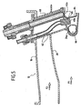
- the figure 5 illustrates a variant in which the burner ring 26a is disposed in the hot primary flow F 1 (which depends on the general design of the reactor).
- the structural elements similar to those previously described bear the same reference numerals. They will not be described again. Due to the location of the burner ring, it is intended to protect the ignition system (specific injector 48a and candle 42a) in a protective sleeve 60 fixed to the housing 16 and communicating with the burner ring. The sheath 60 thus crosses the secondary flow F2.
- the protective sheath has ventilation orifices 62 communicating with the cold secondary flow.
- the inside of the sheath is constantly traversed by a stream of cold air.
- a heat shield 64 is also placed between the injector and the end of the spark plug. It has a passage 65 facing the spray orifice of the specific injector.
- An annular ventilation box 66 is installed inside the burner ring 26a.
- the fuel is injected into the burner ring 26 and the arms 27 and, simultaneously but with different pressure conditions, a small amount of additional fuel is injected through the injector 48.
- the spark produced by the spark plug 42 is created in the spray cone of the injector, which causes the ignition of the fuel injected by the specific injector, then that of the fuel delivered along the burner ring and arms.
Description
L'invention se rapporte à une chambre de post-combustion de turboréacteur et concerne plus particulièrement un perfectionnement du système d'allumage de ladite post-combustion.The invention relates to a turbojet afterburner chamber and relates more particularly to an improvement of the ignition system of said afterburner.
La post-combustion est utilisée dans les avions militaires pour augmenter rapidement la poussée du moteur et par conséquent la vitesse de l'avion lorsque les conditions de vol l'exigent.Post-combustion is used in military aircraft to rapidly increase the engine thrust and consequently the speed of the aircraft when flight conditions require it.
Le
Le
L'invention s'applique à un type voisin de chambre de combustion équipée d'un brûleur annulaire et d'une bougie capable d'engendrer des étincelles pour l'allumage de la post combustion. Dans un tel système, l'extrémité de la bougie est placée en regard d'un point d'une rampe annulaire de distribution de carburant. Dans ce type de post-combustion, en effet, en fonction de l'altitude et de la vitesse de l'avion au moment du déclenchement de ladite post combustion, la pression et la température d'injection du carburant dans la rampe peuvent être trop faibles ou trop variables. On ne peut en effet intervenir directement sur la pression d'injection dans la rampe annulaire. Par conséquent, l'allumage est incertain et, parfois, la post combustion ne se déclenche pas, sans qu'on puisse nécessairement incriminer le fonctionnement de la bougie. L'invention permet de résoudre ce problème.The invention applies to an adjacent type of combustion chamber equipped with an annular burner and a spark plug capable of generating sparks for the ignition of the post combustion. In such a system, the end of the candle is placed opposite a point of an annular fuel distribution ramp. In this type of post-combustion, in fact, depending on the altitude and the speed of the aircraft at the moment of the triggering of said post combustion, the pressure and the fuel injection temperature in the ramp may be too high. weak or too variable. We can not directly intervene on the injection pressure in the annular ramp. Therefore, the ignition is uncertain and sometimes the post combustion does not trigger, without necessarily incriminating the operation of the candle. The invention solves this problem.
Plus particulièrement, l'invention concerne une chambre de post-combustion comportant une rampe annulaire d'injection du carburant de post-combustion et une bougie d'allumage montée au voisinage de ladite rampe annulaire, caractérisé en ce qu'un injecteur d'allumage est installé en regard de ladite bougie et est connecté à des moyens d'alimentation de carburant spécifiques aptes à délivrer ledit carburant sous une pression contrôlée indépendante des conditions d'alimentation de ladite rampe annulaire.More particularly, the invention relates to a post-combustion chamber comprising an annular ramp for injecting the afterburner fuel and a spark plug mounted in the vicinity of said annular ramp, characterized in that an ignition injector is installed next to said spark plug and is connected to specific fuel supply means capable of delivering said fuel under a controlled pressure independent of the supply conditions of said annular ramp.
Ainsi, l'injecteur d'allumage spécifique alimenté par une source de carburant différente de celle qui alimente le brûleur et venant pulvériser du carburant pendant quelques secondes en regard de la bougie d'allumage, garantit la mise à feu de la post-combustion.Thus, the specific ignition injector fed by a fuel source different from that which feeds the burner and spraying fuel for a few seconds opposite the spark plug, ensures the ignition of the afterburner.
Une fois la post-combustion déclenchée, la source d'alimentation spécifique de l'injecteur d'allumage peut être arrêtée jusqu'au prochain déclenchement de post-combustion. La bougie émet plusieurs étincelles par seconde jusqu'à l'allumage. La période d'allumage dure quelques secondes, par exemple entre trois et dix secondes.Once the post-combustion is triggered, the specific power source of the ignition injector can be stopped until the next post-combustion trigger. The spark plug emits several sparks per second until ignition. The ignition period lasts a few seconds, for example between three and ten seconds.
L'injecteur est pourvu d'une buse spéciale qui vaporise le jet en particules très fines inférieures à cinquante microns.The injector is provided with a special nozzle which vaporizes the jet in very fine particles smaller than fifty microns.
Dans un mode de réalisation où la rampe annulaire est montée dans un anneau brûleur, ledit injecteur fait saillie à l'intérieur de cet anneau, à l'arrière de la bougie.In one embodiment where the annular ramp is mounted in a burner ring, said injector protrudes inside this ring at the back of the candle.
Dans une chambre de post-combustion, on distingue classiquement un flux primaire chaud interne où les gaz délivrés par la turbine s'écoulent et un flux secondaire plus froid, externe, séparé du flux primaire par une virole. Dans le cas où l'anneau brûleur est placé dans le flux primaire chaud, l'injecteur et la bougie sont logés dans un fourreau protecteur fixé à un carter extérieur, communément appelé carter de réchauffe et débouchant dans ledit anneau brûleur. Ce fourreau protecteur isole le système d'allumage dudit flux primaire chaud. En outre, le fourreau protecteur comporte avantageusement des orifices de ventilation communiquant avec le flux secondaire froid. De cette façon, de l'air froid circule en permanence à l'intérieur du fourreau protecteur pour maintenir le système d'allumage à une température acceptable.In a post-combustion chamber, there is a classically distinguished internal hot primary stream where the gases delivered by the turbine flow and a secondary colder external stream separated from the primary stream by a ferrule. In the case where the burner ring is placed in the hot primary flow, the injector and the spark plug are housed in a protective sleeve attached to an outer casing, commonly called a heat sink and opening into said burner ring. This protective sheath isolates the ignition system from said hot primary stream. In addition, the protective sheath advantageously comprises ventilation orifices communicating with the cold secondary flow. In this way, cold air circulates continuously inside the protective sleeve to keep the ignition system at an acceptable temperature.
L'invention sera mieux comprise et d'autres avantages de celle-ci apparaîtront mieux à la lumière de la description qui va suivre d'un turboréacteur à chambre de post-combustion conforme à son principe, donnée uniquement à titre d'exemple et faite en référence aux dessins annexés dans lesquels :
- la
figure 1 est une demi-coupe partielle de la partie amont d'une chambre de post-combustion dans laquelle l'anneau brûleur est disposé dans le flux secondaire ; - la
figure 2 montre schématiquement à plus grande échelle la disposition de l'injecteur aéromécanique et de la bougie d'allumage par rapport à l'anneau brûleur ; - la
figure 3 est une vue en perspective de l'anneau brûleur, selon la flèche 3 de lafigure 2 et montrant la connexion de l'injecteur spécifique ; - la
figure 4 est une vue en perspective selon la flèche 4 de lafigure 2 montrant l'anneau brûleur et l'injecteur spécifique ; et - la
figure 5 est une coupe selon un plan radial de la chambre de post combustion montrant le système d'allumage de l'anneau brûleur lorsque ce dernier est situé dans le flux primaire relativement chaud.
- the
figure 1 is a partial half section of the upstream portion of an afterburner chamber in which the burner ring is disposed in the secondary flow; - the
figure 2 schematically shows on a larger scale the arrangement of the aeromechanical injector and the spark plug with respect to the burner ring; - the
figure 3 is a perspective view of the burner ring, according to the arrow 3 of thefigure 2 and showing the connection of the specific injector; - the
figure 4 is a perspective view according to arrow 4 of thefigure 2 showing the burner ring and the specific injector; and - the
figure 5 is a section along a radial plane of the post combustion chamber showing the ignition system of the burner ring when the latter is located in the relatively hot primary stream.
En se reportant aux
Dans l'espace défini entre le carter 18 et le cône 19, d'une part et ledit carter diffuseur 16, d'autre part, se trouve agencée une virole 20 dite "confluence" qui sépare et canalise les flux gazeux primaire F1, intérieur et secondaire F2, extérieur. Le flux primaire F1 des gaz issus de la turbine est à haute température tandis que le flux secondaire F2 provenant du compresseur est à relativement basse température et permet de refroidir les éléments de structure de la chambre de post-combustion. Une chemise interne 22 portée par le carter 14 délimite la chambre de post combustion en aval d'un système de combustion 25 comprenant essentiellement un anneau brûleur 26 et des bras radiaux 27 s'étendant à partir de l'anneau brûleur vers l'intérieur de la chambre de post-combustion jusqu'au voisinage de l'axe X'X de celle-ci.In the space defined between the
La chemise 22 et le carter 14 définissent entre eux un canal de refroidissement 28, annulaire, s'étendant tout autour de la chambre de post combustion 11.The
Les bras radiaux 27 sont au nombre de neuf, régulièrement répartis circonférentiellement. Chaque bras a une section en V dont les ailes divergent vers l'arrière et forment deux rampes rectilignes d'éjection de carburant pulvérisé, constituant une structure dite "accroche-flamme". Chaque bras présente dans sa partie radiale la plus extérieure un élément 30 profilé aérodynamiquement, par lequel il est raccordé au carter 16. Cet élément permet de canaliser le flux secondaire, notamment vers le canal de refroidissement annulaire 28. Ces bras, destinés à entretenir la combustion au centre de la chambre de post-combustion sont de conception classique et ne sont pas concernés par l'invention ; ils ne seront donc pas décrits plus en détail.The
L'anneau brûleur 26 du système de post-combustion 25 est sensiblement de révolution autour de l'axe X'X ; il est porté par les éléments 30. L'anneau brûleur s'ouvre vers l'arrière entre les bras 27 et la chemise interne 22. La partie s'ouvrant vers l'arrière présente une section en V selon un plan radial passant par l'axe X'X. L'anneau brûleur 26 abrite une rampe annulaire d'injection de carburant 34 comprenant un tube de pulvérisation 36 interne, percé d'une pluralité de trous 35 de très faible diamètre et s'étendant à l'intérieur d'un tube protecteur 38 (percé de trous de relativement grand diamètre espacés régulièrement circonférentiellement) formant écran anti-rayonnement pour la protection thermique du tube de pulvérisation. Avantageusement, les trous 35 du tube de pulvérisation 36 coïncident avec les trous du tube protecteur 38. La rampe annulaire 34 s'étend sur pratiquement toute la circonférence de l'anneau brûleur 26. De façon connue, ledit anneau brûleur est alimenté en carburant par un conduit 40 relié à une source d'alimentation principale de carburant, non représenté.The
En un point de l'anneau brûleur 26, une bougie d'allumage 42 est classiquement installée au voisinage de la rampe annulaire de pulvérisation 34. Elle est engagée à coulissement dans un manchon 43 qui comporte une bride 44 coulissant elle-même dans l'espace défini entre la paroi externe de l'anneau brûleur 26 et un cadre 45 soudé à celui-ci, autour du trou par lequel l'extrémité de la bougie pénètre dans ledit anneau brûleur.At a point in the
Selon une caractéristique importante de l'invention, un injecteur d'allumage 48, est installé en regard de ladite bougie 42 et est connecté à des moyens d'alimentation de carburant spécifiques, aptes à délivrer ledit carburant sous une pression contrôlée indépendante des conditions d'alimentation de ladite rampe annulaire. L'injecteur 48 est lui-même dit spécifique puisqu'il est alimenté par une source de carburant spéciale (non représentée) par un conduit particulier 49.According to an important characteristic of the invention, an
L'embout de pulvérisation de l'injecteur 48, qui fait saillie dans l'anneau brûleur est engagé à coulissement dans un manchon 47 qui comporte une bride 50 coulissant elle-même dans l'espace défini entre la paroi de l'anneau brûleur (à l'avant de celui-ci) et un cadre 51 soudé à celui-ci autour du trou par lequel ledit embout pénètre dans l'anneau brûleur.The spray nozzle of the
L'injecteur spécifique 48 est ici du type aéromécanique. Il est muni d'une buse de pulvérisation fine du carburant, capable de délivrer des particules de taille inférieure à cinquante microns. L'injecteur est placé de façon que l'extrémité de la bougie 42 (où se produit l'étincelle) se trouve dans le cône de vaporisation 54 de l'injecteur.The
La
En outre, le fourreau protecteur comporte des orifices de ventilation 62 communiquant avec le flux secondaire froid. Ainsi, l'intérieur du fourreau est en permanence traversé par un courant d'air froid. Un écran de protection thermique 64 est également placé entre l'injecteur et l'extrémité de la bougie. Il présente un passage 65 en regard de l'orifice de pulvérisation de l'injecteur spécifique. Un caisson de ventilation annulaire 66 est installé à l'intérieur de l'anneau brûleur 26a.In addition, the protective sheath has
Au moment de la mise à feu de la post combustion, le carburant est injecté dans l'anneau brûleur 26 et les bras 27 et, simultanément mais avec des conditions de pression différentes, une petite quantité de carburant supplémentaire est injectée grâce à l'injecteur spécifique 48. Les étincelles produites par la bougie 42 se créent dans le cône de pulvérisation de l'injecteur, ce qui provoque l'inflammation du carburant injecté par l'injecteur spécifique, puis celle du carburant délivré le long de l'anneau brûleur et des bras.At the time of ignition of the post combustion, the fuel is injected into the
Claims (6)
- An after-burner chamber (11) comprising an annular duct (34) for after-burner fuel injection and an ignition spark plug (42) mounted in the vicinity of said annular duct, the chamber being characterized in that an ignition injector (48) is installed facing said spark plug and is connected to specific fuel feed means (49) suitable for delivering said fuel under a controlled pressure independent of the feed conditions to said annular duct.
- An after-burner chamber according to claim 1, characterized in that said injector (48) is fitted with a nozzle for spraying said fuel finely.
- An after-burner chamber according to any preceding claim, in which said annular duct is mounted in a burner ring (26), the chamber being characterized in that said injector (48) is mounted in said burner ring (26) and opens out to the inside thereof, in the vicinity of said spark plug.
- An after-burner chamber according to claim 2 or claim 3, of the type in which said burner ring is placed in the hot primary stream (F1) of said after-burner chamber, which chamber is characterized in that the injector (48a) and the spark plug (42a) are housed in a protective sheath (60) fastened to an outer casing and opening out into said burner ring (26a).
- An after-burner chamber according to claim 4, characterized in that said protective sheath has ventilation orifices (62) communicating with the cold secondary stream of said after-burner chamber.
- A turbojet, characterized in that it includes an after-burner chamber according to any preceding claim.
Applications Claiming Priority (1)
| Application Number | Priority Date | Filing Date | Title |
|---|---|---|---|
| FR0407909A FR2873168B1 (en) | 2004-07-16 | 2004-07-16 | TURBOREACTOR COMPRISING A SECURED IGNITION POST-COMBUSTION CHAMBER |
Publications (2)
| Publication Number | Publication Date |
|---|---|
| EP1621817A1 EP1621817A1 (en) | 2006-02-01 |
| EP1621817B1 true EP1621817B1 (en) | 2009-01-28 |
Family
ID=34947700
Family Applications (1)
| Application Number | Title | Priority Date | Filing Date |
|---|---|---|---|
| EP05291480A Active EP1621817B1 (en) | 2004-07-16 | 2005-07-08 | Afterburner with assured ignition |
Country Status (6)
| Country | Link |
|---|---|
| US (1) | US20060292504A1 (en) |
| EP (1) | EP1621817B1 (en) |
| CA (1) | CA2511875A1 (en) |
| DE (1) | DE602005012560D1 (en) |
| FR (1) | FR2873168B1 (en) |
| RU (1) | RU2005122513A (en) |
Families Citing this family (7)
| Publication number | Priority date | Publication date | Assignee | Title |
|---|---|---|---|---|
| FR2900460B1 (en) * | 2006-04-28 | 2012-10-05 | Snecma | ANNULAR POST-COMBUSTION SYSTEM OF A TURBOMACHINE |
| FR2942640B1 (en) | 2009-03-02 | 2011-05-06 | Snecma | POST-COMBUSTION CHAMBER FOR TURBOMACHINE |
| US8893502B2 (en) * | 2011-10-14 | 2014-11-25 | United Technologies Corporation | Augmentor spray bar with tip support bushing |
| CN105716106B (en) * | 2014-12-04 | 2019-07-05 | 中国航空工业集团公司沈阳发动机设计研究所 | A kind of device for realizing hot-shot ignition on exerciser |
| FR3039220B1 (en) * | 2015-07-24 | 2017-08-11 | Snecma | POSTCOMBUSTION DIPOSITIVE FOR TURBOREACTOR |
| FR3097298B1 (en) | 2019-06-12 | 2021-06-04 | Safran Aircraft Engines | CANDLE INTEGRATED INTO THE FLAME HOLDER |
| FR3107570B1 (en) * | 2020-02-26 | 2022-02-04 | Safran Aircraft Engines | POST-COMBUSTION BURNER WITH OPTIMIZED INTEGRATION |
Family Cites Families (12)
| Publication number | Priority date | Publication date | Assignee | Title |
|---|---|---|---|---|
| GB842197A (en) * | 1958-07-23 | 1960-07-20 | Gen Electric | Improvements in afterburner combustion equipment of a gas turbine jet propulsion engine |
| DE1133185B (en) * | 1959-04-21 | 1962-07-12 | Snecma | Combustion device on recoil engines, especially for post-combustion |
| US3016706A (en) * | 1960-09-09 | 1962-01-16 | United Aircraft Corp | Jet ignition system |
| GB938553A (en) * | 1961-05-09 | 1963-10-02 | Rolls Royce | Reheat combustion apparatus for a gas turbine engine |
| DE1240746B (en) * | 1964-08-08 | 1967-05-18 | Heinkel Ag Ernst | Jet nozzle, especially for the afterburner of an aircraft engine, with mechanically controlled jet deflection |
| US3765178A (en) * | 1972-09-08 | 1973-10-16 | Gen Electric | Afterburner flameholder |
| US3931707A (en) * | 1975-01-08 | 1976-01-13 | General Electric Company | Augmentor flameholding apparatus |
| US4170109A (en) * | 1977-11-09 | 1979-10-09 | United Technologies Corporation | Thrust augmentor having swirled flows for combustion stabilization |
| US4315401A (en) * | 1979-11-30 | 1982-02-16 | United Technologies Corporation | Afterburner flameholder construction |
| US5396761A (en) | 1994-04-25 | 1995-03-14 | General Electric Company | Gas turbine engine ignition flameholder with internal impingement cooling |
| FR2770284B1 (en) * | 1997-10-23 | 1999-11-19 | Snecma | CARBIDE AND OPTIMIZED COOLING FLAME HANGER |
| US7437876B2 (en) * | 2005-03-25 | 2008-10-21 | General Electric Company | Augmenter swirler pilot |
-
2004
- 2004-07-16 FR FR0407909A patent/FR2873168B1/en not_active Expired - Fee Related
-
2005
- 2005-07-08 DE DE602005012560T patent/DE602005012560D1/en active Active
- 2005-07-08 EP EP05291480A patent/EP1621817B1/en active Active
- 2005-07-13 CA CA002511875A patent/CA2511875A1/en not_active Abandoned
- 2005-07-15 US US11/181,924 patent/US20060292504A1/en not_active Abandoned
- 2005-07-15 RU RU2005122513/06A patent/RU2005122513A/en not_active Application Discontinuation
Also Published As
| Publication number | Publication date |
|---|---|
| US20060292504A1 (en) | 2006-12-28 |
| RU2005122513A (en) | 2007-01-20 |
| EP1621817A1 (en) | 2006-02-01 |
| FR2873168A1 (en) | 2006-01-20 |
| CA2511875A1 (en) | 2006-01-16 |
| FR2873168B1 (en) | 2008-10-31 |
| DE602005012560D1 (en) | 2009-03-19 |
Similar Documents
| Publication | Publication Date | Title |
|---|---|---|
| EP1621817B1 (en) | Afterburner with assured ignition | |
| EP2501996B1 (en) | Combustion chamber having a ventilated spark plug | |
| EP1278012B1 (en) | Aeromechanical injection system with non-return primary swirler | |
| CA2646959C (en) | Injection system of a fuel and air mixture in a turbine engine combustion system | |
| EP1770333B1 (en) | Anti-coking injector arm | |
| FR2626043A1 (en) | TURBULENCE-FUEL INJECTOR FORMATION DEVICE FOR A COMBUSTION ASSEMBLY IN A GAS TURBINE | |
| FR2931203A1 (en) | FUEL INJECTOR FOR GAS TURBINE AND METHOD FOR MANUFACTURING THE SAME | |
| FR2921463A1 (en) | COMBUSTION CHAMBER OF A TURBOMACHINE | |
| EP3578884B1 (en) | Combustion chamber for a turbomachine | |
| FR3084446A1 (en) | MONOBLOCK COMBUSTION CHAMBER | |
| FR2996286A1 (en) | INJECTION DEVICE FOR A TURBOMACHINE COMBUSTION CHAMBER | |
| FR2942640A1 (en) | POST-COMBUSTION CHAMBER FOR TURBOMACHINE | |
| FR2943119A1 (en) | FUEL INJECTION SYSTEMS IN A TURBOMACHINE COMBUSTION CHAMBER | |
| EP4004443B1 (en) | Combustion chamber comprising secondary injection systems, and fuel supply method | |
| FR3039220A1 (en) | POSTCOMBUSTION DIPOSITIVE FOR TURBOREACTOR | |
| FR3071550A1 (en) | ANNULAR CHAMBER OF COMBUSTION | |
| WO2022223915A1 (en) | Flame-holder device for a turbojet afterburner, comprising three-branched arms | |
| FR3136016A1 (en) | FLAME HOLDER RING FOR TURBORE ENGINE AFTERCOMBUSTION COMPRISING A DUCT FOR HEATING AN ANGULAR SEGMENT OF THE RING | |
| EP4179256B1 (en) | Annular combustion chamber for an aircraft turbomachine | |
| FR2982010A1 (en) | ANNULAR COMBUSTION CHAMBER IN A TURBOMACHINE | |
| WO2022223916A1 (en) | Fuel injection device for a turbojet engine afterburner | |
| WO2022223914A1 (en) | Diffusion cone for the rear part of a jet engine, incorporating a flame-holder ring at the trailing edge | |
| FR3113302A1 (en) | Combustion chamber for a turbomachine | |
| FR3038363A1 (en) | ANNULAR COMBUSTION CHAMBER WITH FIXED DIAPHRAGM, FOR A GAS TURBINE | |
| FR3136017A1 (en) | FLAME HOLDER RING FOR TURBORE ENGINE AFTERCOMBUSTION INCLUDING PRIMARY FLOW SAMPLING SCOPES |
Legal Events
| Date | Code | Title | Description |
|---|---|---|---|
| PUAI | Public reference made under article 153(3) epc to a published international application that has entered the european phase |
Free format text: ORIGINAL CODE: 0009012 |
|
| 17P | Request for examination filed |
Effective date: 20050715 |
|
| AK | Designated contracting states |
Kind code of ref document: A1 Designated state(s): AT BE BG CH CY CZ DE DK EE ES FI FR GB GR HU IE IS IT LI LT LU LV MC NL PL PT RO SE SI SK TR |
|
| AX | Request for extension of the european patent |
Extension state: AL BA HR MK YU |
|
| RAP1 | Party data changed (applicant data changed or rights of an application transferred) |
Owner name: SNECMA |
|
| RIN1 | Information on inventor provided before grant (corrected) |
Inventor name: CHARPENEL, SABINE CONSTANCE MAUD Inventor name: ROCHE, JACQUES-A. Inventor name: BABOEUF, SEBASTIEN PIERRE LOUIS Inventor name: DURAND, DIDIER NOEL |
|
| 17Q | First examination report despatched |
Effective date: 20060831 |
|
| AKX | Designation fees paid |
Designated state(s): DE FR GB SE |
|
| GRAP | Despatch of communication of intention to grant a patent |
Free format text: ORIGINAL CODE: EPIDOSNIGR1 |
|
| GRAS | Grant fee paid |
Free format text: ORIGINAL CODE: EPIDOSNIGR3 |
|
| GRAA | (expected) grant |
Free format text: ORIGINAL CODE: 0009210 |
|
| AK | Designated contracting states |
Kind code of ref document: B1 Designated state(s): DE FR GB SE |
|
| REG | Reference to a national code |
Ref country code: GB Ref legal event code: FG4D Free format text: NOT ENGLISH |
|
| REF | Corresponds to: |
Ref document number: 602005012560 Country of ref document: DE Date of ref document: 20090319 Kind code of ref document: P |
|
| REG | Reference to a national code |
Ref country code: SE Ref legal event code: TRGR |
|
| PLBE | No opposition filed within time limit |
Free format text: ORIGINAL CODE: 0009261 |
|
| STAA | Information on the status of an ep patent application or granted ep patent |
Free format text: STATUS: NO OPPOSITION FILED WITHIN TIME LIMIT |
|
| 26N | No opposition filed |
Effective date: 20091029 |
|
| REG | Reference to a national code |
Ref country code: FR Ref legal event code: PLFP Year of fee payment: 12 |
|
| REG | Reference to a national code |
Ref country code: FR Ref legal event code: PLFP Year of fee payment: 13 |
|
| REG | Reference to a national code |
Ref country code: FR Ref legal event code: CD Owner name: SAFRAN AIRCRAFT ENGINES Effective date: 20170719 |
|
| REG | Reference to a national code |
Ref country code: FR Ref legal event code: PLFP Year of fee payment: 14 |
|
| PGFP | Annual fee paid to national office [announced via postgrant information from national office to epo] |
Ref country code: SE Payment date: 20230622 Year of fee payment: 19 |
|
| PGFP | Annual fee paid to national office [announced via postgrant information from national office to epo] |
Ref country code: GB Payment date: 20230620 Year of fee payment: 19 |
|
| PGFP | Annual fee paid to national office [announced via postgrant information from national office to epo] |
Ref country code: FR Payment date: 20230724 Year of fee payment: 19 Ref country code: DE Payment date: 20230620 Year of fee payment: 19 |