EP1621443A2 - Telescope feature used for energy absorption - Google Patents
Telescope feature used for energy absorption Download PDFInfo
- Publication number
- EP1621443A2 EP1621443A2 EP05076554A EP05076554A EP1621443A2 EP 1621443 A2 EP1621443 A2 EP 1621443A2 EP 05076554 A EP05076554 A EP 05076554A EP 05076554 A EP05076554 A EP 05076554A EP 1621443 A2 EP1621443 A2 EP 1621443A2
- Authority
- EP
- European Patent Office
- Prior art keywords
- steering column
- connecting device
- locking member
- column assembly
- response
- Prior art date
- Legal status (The legal status is an assumption and is not a legal conclusion. Google has not performed a legal analysis and makes no representation as to the accuracy of the status listed.)
- Granted
Links
- 238000010521 absorption reaction Methods 0.000 title 1
- 239000006096 absorbing agent Substances 0.000 claims abstract description 45
- 239000002775 capsule Substances 0.000 claims description 9
- 238000000926 separation method Methods 0.000 description 2
- 208000027418 Wounds and injury Diseases 0.000 description 1
- 230000006378 damage Effects 0.000 description 1
- 230000003116 impacting effect Effects 0.000 description 1
- 208000014674 injury Diseases 0.000 description 1
- 239000000463 material Substances 0.000 description 1
- 239000002184 metal Substances 0.000 description 1
- 230000004048 modification Effects 0.000 description 1
- 238000012986 modification Methods 0.000 description 1
Images

Classifications
-
- B—PERFORMING OPERATIONS; TRANSPORTING
- B62—LAND VEHICLES FOR TRAVELLING OTHERWISE THAN ON RAILS
- B62D—MOTOR VEHICLES; TRAILERS
- B62D1/00—Steering controls, i.e. means for initiating a change of direction of the vehicle
- B62D1/02—Steering controls, i.e. means for initiating a change of direction of the vehicle vehicle-mounted
- B62D1/16—Steering columns
- B62D1/18—Steering columns yieldable or adjustable, e.g. tiltable
- B62D1/19—Steering columns yieldable or adjustable, e.g. tiltable incorporating energy-absorbing arrangements, e.g. by being yieldable or collapsible
- B62D1/195—Yieldable supports for the steering column
-
- B—PERFORMING OPERATIONS; TRANSPORTING
- B62—LAND VEHICLES FOR TRAVELLING OTHERWISE THAN ON RAILS
- B62D—MOTOR VEHICLES; TRAILERS
- B62D1/00—Steering controls, i.e. means for initiating a change of direction of the vehicle
- B62D1/02—Steering controls, i.e. means for initiating a change of direction of the vehicle vehicle-mounted
- B62D1/16—Steering columns
- B62D1/18—Steering columns yieldable or adjustable, e.g. tiltable
- B62D1/184—Mechanisms for locking columns at selected positions
Definitions
- the invention includes a steering column assembly positionable in a vehicle.
- the invention also includes a connecting device releasably attachable to the vehicle.
- the connecting device is moveable between a locked configuration and an unlocked configuration to selectively lock the steering column assembly with respect to the vehicle.
- the invention also includes a first energy absorber disposed between the connecting device and the steering column assembly.
- the first energy absorber is selectively engageable to dissipate energy.
- the first energy absorber is engaged to dissipate energy in response to relative movement between the connecting device and the steering column assembly when the connecting device is in the locked configuration.
- the first energy absorber is disengaged with respect to dissipating energy in response to relative movement between the connecting device and the steering column assembly when the connecting device is in the unlocked configuration.
- the invention allows the steering column to be fixed to the vehicle during normal vehicle handling while also allowing energy to be dissipated in an impact situation.
- the invention can be used in combination with one or more other energy absorbing devices to enhance the dissipation of energy.
- a second energy absorber can be disposed between the steering column and the vehicle to dissipate energy in response to relative movement between the steering column and the vehicle.
- a third energy absorber can be disposed between the connecting device and the vehicle to dissipate energy in response to relative movement between the connecting device and the vehicle.
- an apparatus in a first exemplary embodiment of the invention, includes a steering column assembly 12 that is positionable in a vehicle.
- the apparatus also includes a connecting device 18 that is releasably attachable to the vehicle.
- the connecting device 18 is movable between a locked configuration and an unlocked configuration to selectively lock the steering column assembly 12 with respect to the vehicle.
- the apparatus also includes a first energy absorber 20 disposed between the connecting device 18 and the steering column assembly 12.
- the first energy absorber 20 is engaged to dissipate energy in response to relative movement between the connecting device 18 and the steering column assembly 12 when the connecting device 18 is in the locked configuration.
- the first energy absorber 20 is disengaged with respect to dissipating energy in response to relative movement between the connecting device 18 and the steering column 12 when the connecting device 18 is in the unlocked configuration.
- the connecting device 18 includes a first locking member 30 that is slidably associated with the steering column assembly 12.
- the first locking member 30 is disposed between first and second surfaces 34, 36 defined by the bracket 46 of the first steering column member 14.
- the connecting device 18 also includes a second locking member 32 that is movable between a locked position and an unlocked position.
- the exemplary embodiment of the invention includes a pair of second locking members 32, 32a disposed on opposite sides the first locking member 30. When in the locked position, the second locking member 32 contacts the first locking member 30 and the members 30, 32 are immovably associated with one another. When in the unlocked position, the second locking member 32 is spaced from the first locking member 30.
- a lever 70 engages the second locking member 32.
- a driver of the vehicle can rotate the lever 70 along an arcuate path of movement 72 to move the second locking member 32 from the locked position to the unlocked position.
- the driver can adjust the position of the steering wheel in the vehicle telescopically and tiltably.
- the lever 70 can be rotated back along the path of movement 72 to move the second locking member 32 to the locked position.
- the apparatus 10 includes a biasing device 60 that urges the second locking member 32 to the locked position.
- a separating force is generated when the driver of the vehicle impacts the steering column assembly 12 during a crash. If the generating force is not greater than the second predetermined level of force, the steering column assembly 12 will remain fixed with respect to the vehicle. If the separating force is greater than the second predetermined level of force, the third locking member 42 and the capsule 62 will separate and the connecting device 18 and steering column assembly 12 will concurrently move along a first translating collapse path.
- the connecting device 18 can engage another structure in the vehicle such as a crossbeam and cease to move. After the connecting device 18 ceases to move, the connecting device 18 and the steering column assembly 12 can separate from one another in response to a separating force greater than the first predetermined level of force.
- the steering assembly column 12 will move along a second translating collapse path after separation from the connecting device 18.
- the first locking member 30, the second locking member 32 and the third locking member 44 are fixed relative to one another and the first locking member 30 slides with respect to the bracket 46.
- the strap 24 is drawn over the anvil 22 to dissipate energy.
- the first and second translating collapse paths are disposed in series. As a result, the length over which a deformable member such as the straps 24, 68 can be drawn, is increased.
- the movement of the steering column assembly 12 along either of the first or second translating collapse paths can correspond to telescoping movement of the first and second steering column members 14, 16 relative to one another.
- the first steering column member 14 could be telescopically collapsing relative to the second steering column member 16 during movement of the steering column assembly 12 along one of or both of the first and second translating collapse paths.
- movement of the steering column assembly 12 along both of the first and second collapse paths can be translating movement in which the first and second steering column members 14, 16 are fixed relative to one another.
- the capsule 62 and the third locking member 42 separate in response to a separating force greater than the second predetermined level of force.
- the connecting device 18 and the first steering column member 14 separate in response to a separating force greater than the first predetermined level of force.
- the first predetermined level of force is greater than the second predetermined level of force.
- the capsule 62 and third locking member 42 separate before the connecting device 18 separates from the steering column assembly 12.
- the first predetermined level of force could be less than the second predetermined level of force.
- the capsule 62 and third locking member 42 separate after the connecting device 18 separates from the steering column assembly 12.
- an apparatus 110 in a second exemplary embodiment of the invention, includes a steering column assembly 112 having first and second steering column members 114, 116.
- a connecting device 118 releasably connects the steering column assembly 112 to the vehicle.
- a first energy absorber 120 is disposed between the connecting device 118 and the steering column assembly 112.
- the first energy absorber 120 includes the first anvil 122 and the first strap 124.
- the steering column assembly 112 includes a steering wheel supporting end 126 and a pivoting end 128.
- the connecting device 118 includes a first locking member 130, a second locking member 132, and a third locking member 142.
- the first locking member 130 is disposed between first and second surfaces 134, 136 of a bracket 146.
- the first locking member 130 defines a first locking portion 138.
- the third locking member 142 includes a third locking portion 144 defining a plurality of teeth 154.
- a bracket 146 associated with the first steering column member 114 defines a first slot 148 and the third locking member 142 defines a second slot 150.
- a biasing device 160 biases the second locking member 132 to the locked position.
- a third energy absorber 174 includes a capsule 162 disposed between the third locking member 142 and the vehicle.
- a second energy absorber 164 is disposed in parallel to the third energy absorber 174 and includes a second anvil 166 and a second strap 168.
Landscapes
- Engineering & Computer Science (AREA)
- Chemical & Material Sciences (AREA)
- Combustion & Propulsion (AREA)
- Transportation (AREA)
- Mechanical Engineering (AREA)
- Steering Controls (AREA)
- Lock And Its Accessories (AREA)
- Solid-Sorbent Or Filter-Aiding Compositions (AREA)
- Diaphragms For Electromechanical Transducers (AREA)
Abstract
Description
- The invention relates to an energy absorber associated with a steering system of a vehicle to reduce the likelihood of injury to a driver.
- Steering systems for vehicles often include a device to absorb energy associated with a driver impacting a steering column, as may occur during a vehicle crash. The energy absorbing device often includes a metal strap and an anvil. One end of the strap is fixed to a first structure in the steering column and the anvil is fixed to a second structure in the steering column. The first and second structures move relative to one another during an impact situation and the strap is drawn over the anvil to dissipate energy.
- The invention includes a steering column assembly positionable in a vehicle. The invention also includes a connecting device releasably attachable to the vehicle. The connecting device is moveable between a locked configuration and an unlocked configuration to selectively lock the steering column assembly with respect to the vehicle. The invention also includes a first energy absorber disposed between the connecting device and the steering column assembly. The first energy absorber is selectively engageable to dissipate energy. For example, the first energy absorber is engaged to dissipate energy in response to relative movement between the connecting device and the steering column assembly when the connecting device is in the locked configuration. The first energy absorber is disengaged with respect to dissipating energy in response to relative movement between the connecting device and the steering column assembly when the connecting device is in the unlocked configuration.
- The invention allows the steering column to be fixed to the vehicle during normal vehicle handling while also allowing energy to be dissipated in an impact situation. The invention can be used in combination with one or more other energy absorbing devices to enhance the dissipation of energy. For example, a second energy absorber can be disposed between the steering column and the vehicle to dissipate energy in response to relative movement between the steering column and the vehicle. Also, a third energy absorber can be disposed between the connecting device and the vehicle to dissipate energy in response to relative movement between the connecting device and the vehicle.
- Other advantages of the present invention will be readily appreciated as the same becomes better understood by reference to the following detailed description when considered in connection with the accompanying drawings wherein:
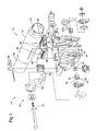
- Figure 1 is an exploded view of a first embodiment of the present invention;
- Figure 2 is a perspective view of the assembled embodiment of Figure 1; and
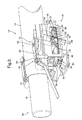
- Figure 3 is a perspective view of a second embodiment of the present invention.
- A plurality of different embodiments of the invention are shown in the Figures of the application. Similar features are shown in the various embodiments of the invention. Similar features have been numbered with a common two-digit reference numeral and have been differentiated by a third digit placed before the two common digits. Similar features are structured similarly, operate similarly, and/or have the same function unless otherwise indicated.
- Referring now to Figures 1 and 2, in a first exemplary embodiment of the invention, an apparatus includes a
steering column assembly 12 that is positionable in a vehicle. The apparatus also includes a connectingdevice 18 that is releasably attachable to the vehicle. The connectingdevice 18 is movable between a locked configuration and an unlocked configuration to selectively lock thesteering column assembly 12 with respect to the vehicle. The apparatus also includes a first energy absorber 20 disposed between the connectingdevice 18 and thesteering column assembly 12. The first energy absorber 20 is engaged to dissipate energy in response to relative movement between the connectingdevice 18 and thesteering column assembly 12 when the connectingdevice 18 is in the locked configuration. The first energy absorber 20 is disengaged with respect to dissipating energy in response to relative movement between the connectingdevice 18 and thesteering column 12 when the connectingdevice 18 is in the unlocked configuration. - The
steering column assembly 12 includes first and secondsteering column members wheel supporting end 26 and the secondsteering column member 16 includes a pivotingend 28 spaced from the steeringwheel supporting end 26. The steeringwheel supporting end 26 is pivotable about the pivotingend 28. Abracket 46 extends from thefirst member 14 to cooperate with the connectingdevice 18. - The first
steering column member 14 is pivotable relative to the connectingdevice 18 about the pivotingend 28. The connectingdevice 18 can prevent both telescoping movement and pivoting movement of the firststeering column member 14. When in the locked configuration, the connectingdevice 18 is immovably associated with the firststeering column member 14 in response to a separating force up to a first predetermined level of force. If the force exceeds the first predetermined level, the connectingdevice 18 and the firststeering column member 14 slide relative to one another. In other words, during an impact situation, the connectingdevice 18 and the firststeering column member 14 will be fixed with respect to one another unless a force acting on thesteering column assembly 12 is greater than the first predetermined level of force. In response to a separating force greater than the first predetermined level, thefirst locking member 30 slides relative to thebracket 46. - The connecting
device 18 includes afirst locking member 30 that is slidably associated with thesteering column assembly 12. Thefirst locking member 30 is disposed between first andsecond surfaces bracket 46 of the firststeering column member 14. The connectingdevice 18 also includes asecond locking member 32 that is movable between a locked position and an unlocked position. The exemplary embodiment of the invention includes a pair ofsecond locking members first locking member 30. When in the locked position, thesecond locking member 32 contacts thefirst locking member 30 and themembers second locking member 32 is spaced from thefirst locking member 30. - The
first locking member 30 includes afirst locking portion 38 and thesecond locking member 32 includes asecond locking portion 40. Thefirst locking portion 38 of the first exemplary embodiment of the invention defines a plurality ofteeth 58. Thesecond locking portion 40 defines a plurality ofteeth 56. The first andsecond locking portions second members first locking portion 38 and thesecond locking portion 40 are interlocked and immovable associated with one another. Theteeth second locking member 32 is in a locked position. When thesecond locking member 32 is in the unlocked position, thelocking portion 38 and thelocking portion 40 are spaced from one another. In other words, Theteeth second locking member 32 is in the unlocked position. The cooperation between thefirst locking portion 38 and thesecond locking portion 40 prevents telescoping movement between the first and secondsteering column members second locking member 32 between the locked and unlocked positions, theteeth 56 move at least partially perpendicular with respect to theteeth 58. - The connecting
device 18 also includes athird locking member 42 releasably attachable to the vehicle and spaced from thefirst locking member 30. In one embodiment of the invention, thethird locking member 42 can be a rake bracket and thesecond locking member 32 can be attached to a rake bolt. The first andthird locking members second locking member 32 being moved to the unlocked position. For example, when thesecond locking member 32 is in the unlocked position, the first andthird locking members second locking member 32 is in the locked position, the first andthird locking members bracket 46 is disposed between the first andthird locking members - The
third locking member 42 includes athird locking portion 44 for cooperating with thesecond locking member 32 to immovably associate the second andthird locking members third locking portion 44 defines a plurality ofteeth 54. Thesecond locking member 30 defines a plurality ofteeth 52 that engage theteeth 54 when thesecond locking member 32 is in the locked position. The engagement between theteeth teeth teeth steering column assembly 12 and the engagement of theteeth steering column assembly 12. - The
bracket 46 defines afirst slot 48 and thethird locking member 42 defines asecond slot 50. Thesecond locking member 32 extends through both the first andsecond slots second locking member 32 is disposed in both the first andsecond slots - In an
apparatus 10 according to the first embodiment of the invention, alever 70 engages thesecond locking member 32. In operation, a driver of the vehicle can rotate thelever 70 along an arcuate path ofmovement 72 to move thesecond locking member 32 from the locked position to the unlocked position. When thesecond locking member 32 is moved to the unlocked position, the driver can adjust the position of the steering wheel in the vehicle telescopically and tiltably. After the steering wheel has been moved to a desired position, thelever 70 can be rotated back along the path ofmovement 72 to move thesecond locking member 32 to the locked position. Theapparatus 10 includes abiasing device 60 that urges thesecond locking member 32 to the locked position. - The
first energy absorber 20 includes afirst anvil 22 that is fixedly associated with either the connectingdevice 18 or the firststeering column member 14. Thefirst energy absorber 20 also includes afirst strap 24 that is fixedly associated with the other of the connectingdevice 18 and the firststeering column member 14. In the first exemplary embodiment of the invention shown in Figures 1 and 2, thestrap 24 is fixedly associated with thebracket 46 of the firststeering column member 14 and theanvil 22 is fixedly associated with the first lockingmember 30. In the second alternative embodiment of the invention, shown in Figure 3, thestrap 124 is fixedly associated with thefirst locking member 130 and theanvil 122 is fixedly associated with thebracket 146. Thestrap 24 is drawable over thefirst anvil 22 to dissipate energy associated with movement of thesteering column assembly 12 relative to the connectingdevice 18. During movement of thesteering column assembly 12 relative to the connectingdevice 18, the first lockingmember 30 slides relative to thebracket 46. - The apparatus also includes a
second energy absorber 64. Thesecond energy absorber 64 dissipates energy in response to relative movement between the connectingdevice 18 and the vehicle. As set forth more fully below, the connectingdevice 18 can move relative to the vehicle. Thesecond energy absorber 64 includes ananvil 66 and astrap 68. One of theanvil 66 andstrap 68 is fixedly associated with the connectingdevice 18. The other of theanvil 66 andstrap 68 is fixedly associated with the vehicle. In the first exemplary embodiment of the invention, theanvil 66 is supported by thethird locking member 42 of the connectingdevice 18 and thestrap 68 is fixedly associated with the vehicle. - The apparatus also includes a
third energy absorber 74 disposed in parallel to thesecond energy absorber 64. Thethird energy absorber 74 dissipates energy in response to relative movement between the connectingdevice 18 and the vehicle. Thethird energy absorber 74 includes at least onecapsule 62 releaseably associated with the connectingdevice 18. For example, thecapsule 62 is releasably associated with thethird locking member 42 of the connectingdevice 18. Thethird energy absorber 74 is movably associated with the connectingdevice 18 in response to a separating force up to a second predetermined level. Thethird energy absorber 74 separates from the connectingdevice 18 in response to a separating force greater than the second predetermined level of force. - In operation, a separating force is generated when the driver of the vehicle impacts the
steering column assembly 12 during a crash. If the generating force is not greater than the second predetermined level of force, thesteering column assembly 12 will remain fixed with respect to the vehicle. If the separating force is greater than the second predetermined level of force, thethird locking member 42 and thecapsule 62 will separate and the connectingdevice 18 andsteering column assembly 12 will concurrently move along a first translating collapse path. - During movement of the connecting
device 18 and thesteering column assembly 12 along the first translating collapse path, separation between thecapsule 62 and thethird locking member 42 dissipates energy. Also, thestrap 68 of thesecond energy absorber 64 is drawn over theanvil 66 and additional energy is dissipated. - During movement along the first translating collapse path, the connecting
device 18 can engage another structure in the vehicle such as a crossbeam and cease to move. After the connectingdevice 18 ceases to move, the connectingdevice 18 and thesteering column assembly 12 can separate from one another in response to a separating force greater than the first predetermined level of force. Thesteering assembly column 12 will move along a second translating collapse path after separation from the connectingdevice 18. During movement of thesteering column assembly 12 along the second translating collapse path, the first lockingmember 30, thesecond locking member 32 and thethird locking member 44 are fixed relative to one another and the first lockingmember 30 slides with respect to thebracket 46. In response, thestrap 24 is drawn over theanvil 22 to dissipate energy. - In the first exemplary embodiment of the invention, the first and second translating collapse paths are disposed in series. As a result, the length over which a deformable member such as the
straps steering column assembly 12 along either of the first or second translating collapse paths can correspond to telescoping movement of the first and secondsteering column members steering column member 14 could be telescopically collapsing relative to the secondsteering column member 16 during movement of thesteering column assembly 12 along one of or both of the first and second translating collapse paths. Alternatively, movement of thesteering column assembly 12 along both of the first and second collapse paths can be translating movement in which the first and secondsteering column members - As set forth above, the
capsule 62 and thethird locking member 42 separate in response to a separating force greater than the second predetermined level of force. Also, the connectingdevice 18 and the firststeering column member 14 separate in response to a separating force greater than the first predetermined level of force. In an exemplary embodiment of the invention, the first predetermined level of force is greater than the second predetermined level of force. In other words, in response to an impact between the driver of the vehicle and thesteering column assembly 12, thecapsule 62 and third lockingmember 42 separate before the connectingdevice 18 separates from thesteering column assembly 12. However, in alternative embodiments of the invention, the first predetermined level of force could be less than the second predetermined level of force. In other words, in response to an impact between the driver of the vehicle and thesteering column assembly 12, thecapsule 62 and third lockingmember 42 separate after the connectingdevice 18 separates from thesteering column assembly 12. - Referring now to Figure 3, in a second exemplary embodiment of the invention, an
apparatus 110 includes asteering column assembly 112 having first and secondsteering column members device 118 releasably connects thesteering column assembly 112 to the vehicle. Afirst energy absorber 120 is disposed between the connectingdevice 118 and thesteering column assembly 112. Thefirst energy absorber 120 includes thefirst anvil 122 and thefirst strap 124. Thesteering column assembly 112 includes a steeringwheel supporting end 126 and a pivotingend 128. - The connecting
device 118 includes afirst locking member 130, asecond locking member 132, and athird locking member 142. Thefirst locking member 130 is disposed between first andsecond surfaces bracket 146. Thefirst locking member 130 defines afirst locking portion 138. Thethird locking member 142 includes athird locking portion 144 defining a plurality ofteeth 154. Abracket 146 associated with the firststeering column member 114 defines afirst slot 148 and thethird locking member 142 defines asecond slot 150. Abiasing device 160 biases thesecond locking member 132 to the locked position. - A
third energy absorber 174 includes acapsule 162 disposed between thethird locking member 142 and the vehicle. Asecond energy absorber 164 is disposed in parallel to thethird energy absorber 174 and includes asecond anvil 166 and asecond strap 168. - While the invention has been described with reference to an exemplary embodiment, it will be understood by those skilled in the art that various changes may be made and equivalents may be substituted for elements thereof without departing from the scope of the invention. In addition, many modifications may be made to adapt a particular situation or material to the teachings of the invention without departing from the essential scope thereof. Therefore, it is intended that the invention not be limited to the particular embodiment disclosed as the best mode contemplated for carrying out this invention, but that the invention will include all embodiments falling within the scope of the appended claims.
Claims (33)
- An apparatus comprising:a steering column assembly (12, 112) positionable in a vehicle; a connecting device (18, 118) releaseably attachable to the vehicle and moveable between locked and unlocked configurations to selectively lock said steering column assembly (12, 112) with respect to the vehicle; anda first energy absorber (20, 120) disposed between said connecting device (18, 118) and said steering column assembly (12, 112) and engaged to dissipate energy in response to relative movement between said connecting device (18, 118) and said steering column assembly (12, 112) when said connecting device (18, 118) is in said locked configuration.
- The apparatus of claim 1 wherein the first energy absorber (20, 120) is further defined as being disengaged to dissipate energy in response to relative movement between said connecting device (18, 118) and said steering column (12, 112) when said connecting device (18, 118) is in said unlocked configuration.
- The apparatus of claim 1 wherein said steering column assembly (12, 112) includes first and second steering column members (14, 114, 16, 116) engaged with one another for telescoping movement.
- The apparatus of claim 3 wherein said first energy absorber (20, 120) includes a first anvil (22, 122) fixedly associated with one of said connecting device (18, 118) and said first steering column member (14, 114) and a first strap (24, 124) drawable over said first anvil (22, 122) and fixedly associated with the other of said connecting device (18, 118) and said first steering column member (14, 114).
- The apparatus of claim 3 wherein said first steering column member (14, 114) is further defined as having a steering wheel supporting end (26, 126) and said second steering column member (16, 116) is further defined as having a pivoting end (28, 128) spaced from said steering wheel supporting end (26, 126).
- The apparatus of claim 3 wherein said first steering column member (14, 114) is pivotable relative to said connecting device (18, 118).
- The apparatus of claim 6 wherein said connecting device (18, 118) prevents both said telescoping movement and pivoting movement of said first steering column member (14, 114).
- The apparatus of claim 3 wherein said connecting device (18, 118) is immovably associated with said first steering column member (14, 114) in response to a separating force up to a first predetermined level of force when in said locked configuration and is slidable relative to said first steering column member (14, 114) in response to separating force greater than the first predetermined level of force when said in said locked configuration.
- The apparatus of claim 1 wherein said connecting device (18, 118) further comprises:a first locking member (30, 130) slidably associated with said steering column assembly (12, 112); anda second locking member (32, 132) moveable between a locked position contacting said first locking member (30, 130) and an unlocked position spaced from said first locking member (30, 130).
- The apparatus of claim 9 wherein said first locking member (30, 130) is pressed between first and second surfaces (34, 134, 36, 136) defined by said first steering column member (14, 114).
- The apparatus of claim 9 wherein said first locking member (30, 130) is immovably associated with said steering column assembly (12, 112) in response to a separating force up to a first predetermined level of force when said second locking member (32, 132) is said locked position and is slidable with respect to said steering column assembly (12, 112) in response to a separating force greater than the first predetermined level of force when second locking member (32, 132) is said locked position.
- The apparatus of claim 9 wherein said first locking member (30, 130) includes a first locking portion (38, 138) and said second locking member (32, 132) includes a second locking portion (40) selectively engageable with said first locking portion (38, 138) to prevent and said telescoping movement.
- The apparatus of claim 9 wherein said connecting device (18, 118) further comprises:a third locking member (42, 142) releaseably attachable to a vehicle and slidably engaged with said first locking member (30, 130).
- The apparatus of claim 13 wherein said first and third locking members (30, 130, 42, 142) are immovably associated with one another in response to said second locking member (32, 132) being moved to said locked position.
- The apparatus of claim 13 wherein said steering column assembly (12, 112) includes a bracket (46, 146) disposed between said first and third locking members (30, 130, 42, 142).
- The apparatus of claim 15 wherein said bracket (46, 146) includes first and second surfaces (34, 134, 36, 136) and said first locking member (30, 130) is further defined as being pressed between first and second surfaces (34, 134, 36, 136).
- The apparatus of claim 13 wherein said first locking member (30, 130) includes a first locking portion (38, 138) and said second locking member (32, 132) includes a second locking portion (40) and said third locking member (42, 142) includes a third locking portion (44, 144), wherein said second locking portion (38, 138) being moveable between an unlocked position spaced from said first and third locking portions (38, 138, 44, 144) and a locked position contacting said second and third locking portions (38, 138, 44, 144).
- The apparatus of claim 17 wherein cooperation between said first locking portion (38, 138) and said second locking portion (40) prevents said telescoping movement and cooperation between said third locking portion (44, 144) and said second locking portion (40) prevents tilting movement.
- The apparatus of claim 18 wherein said bracket (46, 146) defines a first slot (48, 148) and said third locking member (42, 142) defines a second slot (50, 150) and said second locking member (32, 132) extends through said first and second slots (48, 148, 50, 150).
- The apparatus of claim 19 wherein said second locking portion (40) defines a first plurality of teeth (52) and said third locking member (42, 142) defines a second plurality of teeth (54, 154) extending along said second slot (50, 150), wherein said first and second pluralities of teeth (52, 54, 154) engage one another when said second locking member (32, 132) is in said locked position and wherein said first and second pluralities of teeth (52, 54, 154) are spaced from one another when said second locking member (32, 132) is in said unlocked position.
- The apparatus of claim 20 wherein said second locking member (32, 132) moves at least partially perpendicular with respect to said second slot (50, 150) during movement between said locked and unlocked positions.
- The apparatus of claim 21 wherein said second locking member (32, 132) defines a third plurality of teeth (56) and said first locking member (30, 130) defines a fourth plurality of teeth (58, 158) disposed adjacent to said first slot (48, 148), wherein said third and fourth pluralities of teeth (56, 58, 158) engage one another when said second locking member (32, 132) is in said locked position and are spaced from one another when said second locking member (32, 132) is in said unlocked position.
- The apparatus of claim 22 wherein said second locking member (32, 132) moves at least partially perpendicular with respect to said fourth plurality of teeth (58, 158) during movement between said locked and unlocked positions.
- The apparatus of claim 9 including a biasing device (60, 160) urging said second locking member (32, 132) to said locked position.
- The apparatus of claim 1 further comprising:at least one capsule (62, 162) releaseably associated with said connecting device (18, 118) to releaseably attach said first connecting device (18, 118) to a vehicle.
- An apparatus comprising:a steering column assembly (12, 112) positionable in a vehicle; a connecting device (18, 118) releaseably attachable to the vehicle and moveable between locked and unlocked configurations to selectively lock said steering column assembly (12, 112) with respect to the vehicle;a first energy absorber (20, 120) disposed between said connecting device (18, 118) and said steering column assembly (12, 112) and engaged to dissipate energy in response to relative movement between said connecting device (18, 118) and said steering column assembly (12, 112) when said connecting device (18, 118) is in said locked configuration and disengaged to dissipate energy in response to relative movement between said connecting device (18, 118) and said steering column (12, 112) when said connecting device (18, 118) is in said unlocked configuration; anda second energy absorber (64, 164) associated with said connecting device (18, 118) to dissipate energy in response to movement of said connecting device (18, 118) with respect to the vehicle.
- The apparatus of claim 26 further comprising:a third energy absorber (74, 174) disposed in parallel to said second energy absorber (64, 164) to dissipate energy in response to movement of said connecting device (18, 118) with respect to the vehicle.
- The apparatus of claim 27 wherein said first energy absorber (20, 120) includes first anvil (22, 122) fixedly associated with one of said steering column assembly (12, 112) and said connecting device (18, 118) and a first strap (24, 124) drawable over said first anvil (22, 122) and fixedly associated with the other of said steering column assembly (12, 112) and said connecting device (18, 118) and wherein said second energy absorber (64, 164) includes a second anvil (66, 166) fixedly associated with one of said connecting device (18, 118) and said third energy absorber and a second strap (68, 168) drawable over said second anvil (66, 166) and fixedly associated with the other of said connecting device (18, 118) and said third energy absorber.
- The apparatus of claim 28 wherein said third energy absorber is further defined as being immovably associated with said connecting device (18, 118) in response to a separating force up to a second predetermined level of force and as being separable from said connecting device (18, 118) in response to a separating force greater than the second predetermined level of force.
- The apparatus of claim 29 wherein said connecting device (18, 118) is immovably associated with said steering column assembly (12, 112) in response to a separating force up to a first predetermined level of force and as being slidably associated with said steering column assembly (12, 112) in response to a separating force greater than the first predetermined level of force, wherein said first predetermined level of force is greater than said second predetermined level of force.
- A method comprising the steps of:connecting a steering column assembly (12, 112) to a vehicle with a connecting device (18, 118) such that the steering column assembly (12, 112) is adjustable for telescoping and tilting movement and fixed with respect to translating movement during normal vehicle handling;releasing the connecting device (18, 118) from the vehicle in response to an application of a second predetermined collapse force applied to the steering column assembly (12, 112) to move the steering column assembly (12, 112) along a first collapse path;absorbing energy associated with the movement of the steering column assembly (12, 112) along the first collapse path with a first energy absorber (20, 120) supported by the connecting device (18, 118);releasing the steering column assembly (12, 112) from the connecting device (18, 118) in response to the application of a first predetermined collapse force applied to the steering column assembly (12, 112) to move the steering column assembly (12, 112) along a second collapse path; andabsorbing energy associated with the movement of the steering column assembly (12, 112) along the second collapse path with a second energy absorber (64, 164) supported by the connecting device (18, 118).
- The method of claim 31 including the step of:disposing the first and second collapse paths in series.
- The method of claim 31 including the step of:telescopically collapsing the steering column assembly (12, 112) during at least a portion of movement along the second collapse path.
Applications Claiming Priority (1)
| Application Number | Priority Date | Filing Date | Title |
|---|---|---|---|
| US10/899,811 US7484430B2 (en) | 2004-07-27 | 2004-07-27 | Telescope feature used for energy absorption |
Publications (3)
| Publication Number | Publication Date |
|---|---|
| EP1621443A2 true EP1621443A2 (en) | 2006-02-01 |
| EP1621443A3 EP1621443A3 (en) | 2006-05-24 |
| EP1621443B1 EP1621443B1 (en) | 2008-02-06 |
Family
ID=35159673
Family Applications (1)
| Application Number | Title | Priority Date | Filing Date |
|---|---|---|---|
| EP05076554A Expired - Lifetime EP1621443B1 (en) | 2004-07-27 | 2005-07-07 | Telescope feature used for energy absorption |
Country Status (4)
| Country | Link |
|---|---|
| US (1) | US7484430B2 (en) |
| EP (1) | EP1621443B1 (en) |
| AT (1) | ATE385487T1 (en) |
| DE (1) | DE602005004632T2 (en) |
Cited By (1)
| Publication number | Priority date | Publication date | Assignee | Title |
|---|---|---|---|---|
| EP2296956B1 (en) * | 2008-06-04 | 2016-10-26 | Robert Bosch Automotive Steering Vendôme | Improved adjustable steering column for motor vehicles |
Families Citing this family (35)
| Publication number | Priority date | Publication date | Assignee | Title |
|---|---|---|---|---|
| US7942446B2 (en) * | 2004-04-30 | 2011-05-17 | Nexteer (Beijing) Technology Co., Ltd. | Horizontal hybrid collapsing steering column |
| US7421925B2 (en) * | 2004-12-16 | 2008-09-09 | William Korzan | Steering column tilt adjusting system |
| US7861615B2 (en) * | 2005-04-19 | 2011-01-04 | Gm Global Technology Operations, Inc. | Adjustable steering column assembly |
| US20060230863A1 (en) * | 2005-04-19 | 2006-10-19 | Delphi Technologies, Inc. | Steering column with rake and telescope adjustment |
| US8056437B2 (en) * | 2005-04-19 | 2011-11-15 | Nexteer (Beijing) Technology Co., Ltd. | Electric steering column lock with single direction actuator travel |
| DE102005052123B3 (en) * | 2005-10-28 | 2007-01-11 | Thyssenkrupp Presta Ag | Steering column for a vehicle comprises a support unit having side parts lying on both sides of an adjusting unit |
| US20070242160A1 (en) * | 2006-04-18 | 2007-10-18 | Marvell International Ltd. | Shared memory multi video channel display apparatus and methods |
| US20070295145A1 (en) * | 2006-05-30 | 2007-12-27 | Nsk Ltd. | Steering device |
| US7611165B2 (en) * | 2006-06-23 | 2009-11-03 | Delphi Technologies, Inc. | Adjustable steering column assembly having an attached instrument cluster |
| US7533594B2 (en) * | 2006-12-13 | 2009-05-19 | Delphi Technologies, Inc. | Position control apparatus for steering column |
| US7635149B2 (en) * | 2007-03-21 | 2009-12-22 | Gm Global Technology Operations, Inc. | Rocker-arm lock device of an adjustable steering column assembly |
| US8047096B2 (en) * | 2007-03-30 | 2011-11-01 | Nexteer (Beijing) Technology Co., Ltd. | Lock mechanism for an adjustable steering column assembly |
| US7685903B2 (en) * | 2008-05-19 | 2010-03-30 | Gm Global Technology Operations, Inc. | Dual on-center column lock mechanism |
| DE102008034807B3 (en) * | 2008-07-24 | 2009-10-01 | Thyssenkrupp Presta Ag | Steering column for a motor vehicle |
| JP5412799B2 (en) * | 2008-11-13 | 2014-02-12 | 株式会社ジェイテクト | Steering device |
| DE102010044495B4 (en) * | 2009-09-07 | 2014-07-03 | Mando Corporation | Steering column for a vehicle |
| DE102009059159B3 (en) | 2009-12-16 | 2011-01-27 | Thyssenkrupp Presta Ag | Steering column for motor vehicle, has casing unit that is pretensioned by bending wire with respect to support part when unit is moved parallel to longitudinal axis of steering shaft toward vehicle front |
| US8657338B2 (en) * | 2012-06-29 | 2014-02-25 | Steering Solutions Ip Holding Corporation | Position lock for steering column |
| US8888131B2 (en) * | 2012-06-29 | 2014-11-18 | Steering Solutions Ip Holding Corporation | Position lock for steering column |
| US20140109714A1 (en) * | 2012-10-19 | 2014-04-24 | Steering Solutions Ip Holding Corporation | Cross axis rake and telescope lock |
| US8764064B2 (en) * | 2012-11-30 | 2014-07-01 | Steering Solutions Ip Holding Corporation | Steering column assembly with improved energy absorption system |
| US9545943B2 (en) * | 2014-09-17 | 2017-01-17 | Jtekt Corporation | Steering device |
| DE102014016510B4 (en) * | 2014-11-10 | 2016-02-18 | Thyssenkrupp Ag | Steering column with longitudinal stop with adjustable release function for crash |
| KR101603020B1 (en) * | 2014-12-18 | 2016-03-21 | 주식회사 만도 | Steering Column Of Vehicle |
| DE102015204476B3 (en) * | 2015-03-12 | 2016-05-25 | Thyssenkrupp Ag | Steering column for a motor vehicle |
| JP6508518B2 (en) * | 2015-03-31 | 2019-05-08 | 株式会社ジェイテクト | Steering device |
| WO2016172276A1 (en) * | 2015-04-24 | 2016-10-27 | Robert Bosch Automotive Steering Llc | Adjustable steering column lock |
| US10046789B2 (en) * | 2015-05-19 | 2018-08-14 | Nsk Ltd. | Telescopic steering device |
| GB201514096D0 (en) * | 2015-08-10 | 2015-09-23 | Trw Ltd | A Steering Column Assembly |
| JP6659428B2 (en) * | 2016-03-31 | 2020-03-04 | 富士機工株式会社 | Steering column device |
| JP6621359B2 (en) * | 2016-03-31 | 2019-12-18 | 富士機工株式会社 | Steering column device |
| WO2017175825A1 (en) * | 2016-04-08 | 2017-10-12 | 日本精工株式会社 | Position adjustment device for steering wheel |
| DE102018201029B4 (en) * | 2017-01-26 | 2024-10-31 | Hl Mando Corporation | TILT DEVICE FOR AUTOMOTIVE STEERING COLUMN |
| US10717457B2 (en) * | 2018-06-18 | 2020-07-21 | Steering Solutions Ip Holding Corporation | Steering column positive lock mechanism |
| JP7004417B2 (en) * | 2018-08-31 | 2022-01-21 | 株式会社クボタ | Traveling vehicle |
Family Cites Families (9)
| Publication number | Priority date | Publication date | Assignee | Title |
|---|---|---|---|---|
| GB2291840A (en) | 1994-07-29 | 1996-02-07 | Torrington Co | Vehicle steering column reach adjustment and energy absorbing mechanism |
| US5820163A (en) * | 1996-07-08 | 1998-10-13 | Ford Global Technologies, Inc. | Tilting, telescoping and energy absorbing steering column |
| SE507771C2 (en) | 1996-11-21 | 1998-07-13 | Volvo Ab | Device and method of protection of occupants in vehicles |
| EP1192072B1 (en) | 1999-06-11 | 2003-11-26 | Delphi Technologies, Inc. | Energy absorber for motor vehicle steering column |
| US6419269B1 (en) | 1999-09-20 | 2002-07-16 | Delphi Technologies | Locking system for adjustable position steering column |
| US6189929B1 (en) | 1999-11-02 | 2001-02-20 | Trw Inc. | Adaptive collapsible steering column |
| DE10039792A1 (en) * | 2000-08-16 | 2002-02-28 | Daimler Chrysler Ag | Steering column for a motor vehicle |
| US6659504B2 (en) | 2001-05-18 | 2003-12-09 | Delphi Technologies, Inc. | Steering column for a vehicle |
| US6652002B2 (en) | 2001-10-19 | 2003-11-25 | Delphi Technologies, Inc. | Crash responsive energy absorbing device for a steering column |
-
2004
- 2004-07-27 US US10/899,811 patent/US7484430B2/en active Active
-
2005
- 2005-07-07 EP EP05076554A patent/EP1621443B1/en not_active Expired - Lifetime
- 2005-07-07 DE DE602005004632T patent/DE602005004632T2/en not_active Expired - Lifetime
- 2005-07-07 AT AT05076554T patent/ATE385487T1/en not_active IP Right Cessation
Non-Patent Citations (1)
| Title |
|---|
| None |
Cited By (1)
| Publication number | Priority date | Publication date | Assignee | Title |
|---|---|---|---|---|
| EP2296956B1 (en) * | 2008-06-04 | 2016-10-26 | Robert Bosch Automotive Steering Vendôme | Improved adjustable steering column for motor vehicles |
Also Published As
| Publication number | Publication date |
|---|---|
| EP1621443A3 (en) | 2006-05-24 |
| ATE385487T1 (en) | 2008-02-15 |
| US7484430B2 (en) | 2009-02-03 |
| DE602005004632T2 (en) | 2009-01-29 |
| EP1621443B1 (en) | 2008-02-06 |
| DE602005004632D1 (en) | 2008-03-20 |
| US20060021460A1 (en) | 2006-02-02 |
Similar Documents
| Publication | Publication Date | Title |
|---|---|---|
| EP1621443B1 (en) | Telescope feature used for energy absorption | |
| EP0772541B1 (en) | Vehicle steering column adjustment and energy absorbing mechanism | |
| US7325834B2 (en) | Adaptive strap energy absorber with pin puller | |
| EP1705098B1 (en) | Quick release bolt | |
| EP0598857B1 (en) | Device to absorb energy transmitted through steering column for a vehicle | |
| US7735868B2 (en) | Adjustable steering column assembly for a vehicle | |
| EP2022699B1 (en) | An adjustable steering column assembly for a motor vehicle | |
| US8979128B2 (en) | Collapsible steering column assembly | |
| US9481390B2 (en) | Collapsible steering column assembly | |
| US6419269B1 (en) | Locking system for adjustable position steering column | |
| CN109789890B (en) | Collapsing steering column assembly | |
| US20100275721A1 (en) | Clamp assembly for a steering column assembly | |
| EP1728702A1 (en) | Adaptive energy absorber for steering column | |
| US20120125139A1 (en) | Steering column telescope lock | |
| EP1975036A2 (en) | Lock mechanism for an adjustable steering column assembly | |
| CN111712424B (en) | Steering column with adjusting limit stop piece | |
| CN109923023B (en) | Steering column assembly | |
| EP1728703B1 (en) | Adaptive energy absorber for steering column | |
| JPH0899640A (en) | Vehicle steering column | |
| US10807632B2 (en) | Low initial resistance steering column crash apparatus | |
| US20050248141A1 (en) | Adaptive energy absorbing system using pin pullers | |
| EP1593580A1 (en) | Adaptive energy absorber | |
| US20130305870A1 (en) | System and method for constraining a portion of a steering column assembly to translate along a preferred path | |
| WO2018025159A1 (en) | Low initial resistance steering column crash apparatus |
Legal Events
| Date | Code | Title | Description |
|---|---|---|---|
| PUAI | Public reference made under article 153(3) epc to a published international application that has entered the european phase |
Free format text: ORIGINAL CODE: 0009012 |
|
| AK | Designated contracting states |
Kind code of ref document: A2 Designated state(s): AT BE BG CH CY CZ DE DK EE ES FI FR GB GR HU IE IS IT LI LT LU LV MC NL PL PT RO SE SI SK TR |
|
| AX | Request for extension of the european patent |
Extension state: AL BA HR MK YU |
|
| PUAL | Search report despatched |
Free format text: ORIGINAL CODE: 0009013 |
|
| AK | Designated contracting states |
Kind code of ref document: A3 Designated state(s): AT BE BG CH CY CZ DE DK EE ES FI FR GB GR HU IE IS IT LI LT LU LV MC NL PL PT RO SE SI SK TR |
|
| AX | Request for extension of the european patent |
Extension state: AL BA HR MK YU |
|
| 17P | Request for examination filed |
Effective date: 20061124 |
|
| AKX | Designation fees paid |
Designated state(s): AT BE BG CH CY CZ DE DK EE ES FI FR GB GR HU IE IS IT LI LT LU LV MC NL PL PT RO SE SI SK TR |
|
| 17Q | First examination report despatched |
Effective date: 20070104 |
|
| GRAP | Despatch of communication of intention to grant a patent |
Free format text: ORIGINAL CODE: EPIDOSNIGR1 |
|
| GRAS | Grant fee paid |
Free format text: ORIGINAL CODE: EPIDOSNIGR3 |
|
| GRAA | (expected) grant |
Free format text: ORIGINAL CODE: 0009210 |
|
| AK | Designated contracting states |
Kind code of ref document: B1 Designated state(s): AT BE BG CH CY CZ DE DK EE ES FI FR GB GR HU IE IS IT LI LT LU LV MC NL PL PT RO SE SI SK TR |
|
| REG | Reference to a national code |
Ref country code: GB Ref legal event code: FG4D |
|
| REG | Reference to a national code |
Ref country code: CH Ref legal event code: EP |
|
| REG | Reference to a national code |
Ref country code: IE Ref legal event code: FG4D |
|
| REF | Corresponds to: |
Ref document number: 602005004632 Country of ref document: DE Date of ref document: 20080320 Kind code of ref document: P |
|
| PG25 | Lapsed in a contracting state [announced via postgrant information from national office to epo] |
Ref country code: IS Free format text: LAPSE BECAUSE OF FAILURE TO SUBMIT A TRANSLATION OF THE DESCRIPTION OR TO PAY THE FEE WITHIN THE PRESCRIBED TIME-LIMIT Effective date: 20080606 Ref country code: ES Free format text: LAPSE BECAUSE OF FAILURE TO SUBMIT A TRANSLATION OF THE DESCRIPTION OR TO PAY THE FEE WITHIN THE PRESCRIBED TIME-LIMIT Effective date: 20080517 Ref country code: FI Free format text: LAPSE BECAUSE OF FAILURE TO SUBMIT A TRANSLATION OF THE DESCRIPTION OR TO PAY THE FEE WITHIN THE PRESCRIBED TIME-LIMIT Effective date: 20080206 |
|
| NLV1 | Nl: lapsed or annulled due to failure to fulfill the requirements of art. 29p and 29m of the patents act | ||
| PG25 | Lapsed in a contracting state [announced via postgrant information from national office to epo] |
Ref country code: AT Free format text: LAPSE BECAUSE OF FAILURE TO SUBMIT A TRANSLATION OF THE DESCRIPTION OR TO PAY THE FEE WITHIN THE PRESCRIBED TIME-LIMIT Effective date: 20080206 |
|
| ET | Fr: translation filed | ||
| PG25 | Lapsed in a contracting state [announced via postgrant information from national office to epo] |
Ref country code: PL Free format text: LAPSE BECAUSE OF FAILURE TO SUBMIT A TRANSLATION OF THE DESCRIPTION OR TO PAY THE FEE WITHIN THE PRESCRIBED TIME-LIMIT Effective date: 20080206 Ref country code: SI Free format text: LAPSE BECAUSE OF FAILURE TO SUBMIT A TRANSLATION OF THE DESCRIPTION OR TO PAY THE FEE WITHIN THE PRESCRIBED TIME-LIMIT Effective date: 20080206 Ref country code: LV Free format text: LAPSE BECAUSE OF FAILURE TO SUBMIT A TRANSLATION OF THE DESCRIPTION OR TO PAY THE FEE WITHIN THE PRESCRIBED TIME-LIMIT Effective date: 20080206 Ref country code: BE Free format text: LAPSE BECAUSE OF FAILURE TO SUBMIT A TRANSLATION OF THE DESCRIPTION OR TO PAY THE FEE WITHIN THE PRESCRIBED TIME-LIMIT Effective date: 20080206 |
|
| PG25 | Lapsed in a contracting state [announced via postgrant information from national office to epo] |
Ref country code: PT Free format text: LAPSE BECAUSE OF FAILURE TO SUBMIT A TRANSLATION OF THE DESCRIPTION OR TO PAY THE FEE WITHIN THE PRESCRIBED TIME-LIMIT Effective date: 20080707 Ref country code: CZ Free format text: LAPSE BECAUSE OF FAILURE TO SUBMIT A TRANSLATION OF THE DESCRIPTION OR TO PAY THE FEE WITHIN THE PRESCRIBED TIME-LIMIT Effective date: 20080206 Ref country code: SK Free format text: LAPSE BECAUSE OF FAILURE TO SUBMIT A TRANSLATION OF THE DESCRIPTION OR TO PAY THE FEE WITHIN THE PRESCRIBED TIME-LIMIT Effective date: 20080206 Ref country code: DK Free format text: LAPSE BECAUSE OF FAILURE TO SUBMIT A TRANSLATION OF THE DESCRIPTION OR TO PAY THE FEE WITHIN THE PRESCRIBED TIME-LIMIT Effective date: 20080206 Ref country code: NL Free format text: LAPSE BECAUSE OF FAILURE TO SUBMIT A TRANSLATION OF THE DESCRIPTION OR TO PAY THE FEE WITHIN THE PRESCRIBED TIME-LIMIT Effective date: 20080206 Ref country code: SE Free format text: LAPSE BECAUSE OF FAILURE TO SUBMIT A TRANSLATION OF THE DESCRIPTION OR TO PAY THE FEE WITHIN THE PRESCRIBED TIME-LIMIT Effective date: 20080506 |
|
| PG25 | Lapsed in a contracting state [announced via postgrant information from national office to epo] |
Ref country code: RO Free format text: LAPSE BECAUSE OF FAILURE TO SUBMIT A TRANSLATION OF THE DESCRIPTION OR TO PAY THE FEE WITHIN THE PRESCRIBED TIME-LIMIT Effective date: 20080206 |
|
| PLBE | No opposition filed within time limit |
Free format text: ORIGINAL CODE: 0009261 |
|
| STAA | Information on the status of an ep patent application or granted ep patent |
Free format text: STATUS: NO OPPOSITION FILED WITHIN TIME LIMIT |
|
| 26N | No opposition filed |
Effective date: 20081107 |
|
| PG25 | Lapsed in a contracting state [announced via postgrant information from national office to epo] |
Ref country code: LT Free format text: LAPSE BECAUSE OF FAILURE TO SUBMIT A TRANSLATION OF THE DESCRIPTION OR TO PAY THE FEE WITHIN THE PRESCRIBED TIME-LIMIT Effective date: 20080206 |
|
| PG25 | Lapsed in a contracting state [announced via postgrant information from national office to epo] |
Ref country code: MC Free format text: LAPSE BECAUSE OF NON-PAYMENT OF DUE FEES Effective date: 20080731 |
|
| PG25 | Lapsed in a contracting state [announced via postgrant information from national office to epo] |
Ref country code: EE Free format text: LAPSE BECAUSE OF FAILURE TO SUBMIT A TRANSLATION OF THE DESCRIPTION OR TO PAY THE FEE WITHIN THE PRESCRIBED TIME-LIMIT Effective date: 20080206 Ref country code: BG Free format text: LAPSE BECAUSE OF FAILURE TO SUBMIT A TRANSLATION OF THE DESCRIPTION OR TO PAY THE FEE WITHIN THE PRESCRIBED TIME-LIMIT Effective date: 20080506 |
|
| PG25 | Lapsed in a contracting state [announced via postgrant information from national office to epo] |
Ref country code: IE Free format text: LAPSE BECAUSE OF NON-PAYMENT OF DUE FEES Effective date: 20080707 Ref country code: CY Free format text: LAPSE BECAUSE OF FAILURE TO SUBMIT A TRANSLATION OF THE DESCRIPTION OR TO PAY THE FEE WITHIN THE PRESCRIBED TIME-LIMIT Effective date: 20080206 |
|
| PG25 | Lapsed in a contracting state [announced via postgrant information from national office to epo] |
Ref country code: IT Free format text: LAPSE BECAUSE OF FAILURE TO SUBMIT A TRANSLATION OF THE DESCRIPTION OR TO PAY THE FEE WITHIN THE PRESCRIBED TIME-LIMIT Effective date: 20080206 |
|
| REG | Reference to a national code |
Ref country code: CH Ref legal event code: PL |
|
| PG25 | Lapsed in a contracting state [announced via postgrant information from national office to epo] |
Ref country code: CH Free format text: LAPSE BECAUSE OF NON-PAYMENT OF DUE FEES Effective date: 20090731 Ref country code: LI Free format text: LAPSE BECAUSE OF NON-PAYMENT OF DUE FEES Effective date: 20090731 |
|
| PG25 | Lapsed in a contracting state [announced via postgrant information from national office to epo] |
Ref country code: LU Free format text: LAPSE BECAUSE OF NON-PAYMENT OF DUE FEES Effective date: 20080707 Ref country code: HU Free format text: LAPSE BECAUSE OF FAILURE TO SUBMIT A TRANSLATION OF THE DESCRIPTION OR TO PAY THE FEE WITHIN THE PRESCRIBED TIME-LIMIT Effective date: 20080807 |
|
| REG | Reference to a national code |
Ref country code: FR Ref legal event code: TP |
|
| PG25 | Lapsed in a contracting state [announced via postgrant information from national office to epo] |
Ref country code: TR Free format text: LAPSE BECAUSE OF FAILURE TO SUBMIT A TRANSLATION OF THE DESCRIPTION OR TO PAY THE FEE WITHIN THE PRESCRIBED TIME-LIMIT Effective date: 20080206 |
|
| PG25 | Lapsed in a contracting state [announced via postgrant information from national office to epo] |
Ref country code: GR Free format text: LAPSE BECAUSE OF FAILURE TO SUBMIT A TRANSLATION OF THE DESCRIPTION OR TO PAY THE FEE WITHIN THE PRESCRIBED TIME-LIMIT Effective date: 20080507 |
|
| REG | Reference to a national code |
Ref country code: GB Ref legal event code: 732E Free format text: REGISTERED BETWEEN 20101028 AND 20101103 |
|
| REG | Reference to a national code |
Ref country code: DE Ref legal event code: R081 Ref document number: 602005004632 Country of ref document: DE Owner name: GM GLOBAL TECHNOLOGY OPERATIONS LLC (N. D. GES, US Free format text: FORMER OWNER: DELPHI TECHNOLOGIES, INC., TROY, US Effective date: 20110412 Ref country code: DE Ref legal event code: R081 Ref document number: 602005004632 Country of ref document: DE Owner name: STEERING SOLUTIONS IP HOLDING CORP., US Free format text: FORMER OWNER: DELPHI TECHNOLOGIES, INC., TROY, US Effective date: 20110412 Ref country code: DE Ref legal event code: R081 Ref document number: 602005004632 Country of ref document: DE Owner name: STEERING SOLUTIONS IP HOLDING CORP., SAGINAW, US Free format text: FORMER OWNER: DELPHI TECHNOLOGIES, INC., TROY, MICH., US Effective date: 20110412 Ref country code: DE Ref legal event code: R081 Ref document number: 602005004632 Country of ref document: DE Owner name: GM GLOBAL TECHNOLOGY OPERATIONS LLC (N. D. GES, US Free format text: FORMER OWNER: DELPHI TECHNOLOGIES, INC., TROY, MICH., US Effective date: 20110412 |
|
| REG | Reference to a national code |
Ref country code: DE Ref legal event code: R082 Ref document number: 602005004632 Country of ref document: DE Representative=s name: MANITZ, FINSTERWALD & PARTNER GBR, DE |
|
| PGFP | Annual fee paid to national office [announced via postgrant information from national office to epo] |
Ref country code: GB Payment date: 20120725 Year of fee payment: 8 |
|
| REG | Reference to a national code |
Ref country code: DE Ref legal event code: R081 Ref document number: 602005004632 Country of ref document: DE Owner name: STEERING SOLUTIONS IP HOLDING CORP., US Free format text: FORMER OWNER: GM GLOBAL TECHNOLOGY OPERATIONS, INC., DETROIT, US Effective date: 20121019 Ref country code: DE Ref legal event code: R081 Ref document number: 602005004632 Country of ref document: DE Owner name: GM GLOBAL TECHNOLOGY OPERATIONS LLC (N. D. GES, US Free format text: FORMER OWNER: GM GLOBAL TECHNOLOGY OPERATIONS, INC., DETROIT, US Effective date: 20121019 Ref country code: DE Ref legal event code: R082 Ref document number: 602005004632 Country of ref document: DE Representative=s name: MANITZ, FINSTERWALD & PARTNER GBR, DE Effective date: 20121019 Ref country code: DE Ref legal event code: R081 Ref document number: 602005004632 Country of ref document: DE Owner name: GM GLOBAL TECHNOLOGY OPERATIONS LLC (N. D. GES, US Free format text: FORMER OWNER: GM GLOBAL TECHNOLOGY OPERATIONS, INC., DETROIT, MICH., US Effective date: 20121019 Ref country code: DE Ref legal event code: R081 Ref document number: 602005004632 Country of ref document: DE Owner name: STEERING SOLUTIONS IP HOLDING CORP., SAGINAW, US Free format text: FORMER OWNER: GM GLOBAL TECHNOLOGY OPERATIONS, INC., DETROIT, MICH., US Effective date: 20121019 |
|
| PGFP | Annual fee paid to national office [announced via postgrant information from national office to epo] |
Ref country code: FR Payment date: 20120731 Year of fee payment: 8 Ref country code: DE Payment date: 20120727 Year of fee payment: 8 |
|
| REG | Reference to a national code |
Ref country code: DE Ref legal event code: R082 Ref document number: 602005004632 Country of ref document: DE Representative=s name: MANITZ, FINSTERWALD & PARTNER GBR, DE |
|
| REG | Reference to a national code |
Ref country code: DE Ref legal event code: R081 Ref document number: 602005004632 Country of ref document: DE Owner name: GM GLOBAL TECHNOLOGY OPERATIONS LLC (N. D. GES, US Free format text: FORMER OWNER: GM GLOBAL TECHNOLOGY OPERATIONS LLC (N. D. GES. D. STAATES DELAWARE), DETROIT, US Effective date: 20130313 Ref country code: DE Ref legal event code: R082 Ref document number: 602005004632 Country of ref document: DE Representative=s name: MANITZ, FINSTERWALD & PARTNER GBR, DE Effective date: 20130313 Ref country code: DE Ref legal event code: R081 Ref document number: 602005004632 Country of ref document: DE Owner name: STEERING SOLUTIONS IP HOLDING CORP., US Free format text: FORMER OWNER: GM GLOBAL TECHNOLOGY OPERATIONS LLC (N. D. GES. D. STAATES DELAWARE), DETROIT, US Effective date: 20130313 Ref country code: DE Ref legal event code: R081 Ref document number: 602005004632 Country of ref document: DE Owner name: GM GLOBAL TECHNOLOGY OPERATIONS LLC (N. D. GES, US Free format text: FORMER OWNER: GM GLOBAL TECHNOLOGY OPERATIONS LLC (N. D. GES. D. STAATES DELAWARE), DETROIT, MICH., US Effective date: 20130313 Ref country code: DE Ref legal event code: R081 Ref document number: 602005004632 Country of ref document: DE Owner name: STEERING SOLUTIONS IP HOLDING CORP., SAGINAW, US Free format text: FORMER OWNER: GM GLOBAL TECHNOLOGY OPERATIONS LLC (N. D. GES. D. STAATES DELAWARE), DETROIT, MICH., US Effective date: 20130313 |
|
| REG | Reference to a national code |
Ref country code: GB Ref legal event code: 732E Free format text: REGISTERED BETWEEN 20131010 AND 20131016 |
|
| GBPC | Gb: european patent ceased through non-payment of renewal fee |
Effective date: 20130707 |
|
| REG | Reference to a national code |
Ref country code: FR Ref legal event code: ST Effective date: 20140331 |
|
| PG25 | Lapsed in a contracting state [announced via postgrant information from national office to epo] |
Ref country code: DE Free format text: LAPSE BECAUSE OF NON-PAYMENT OF DUE FEES Effective date: 20140201 Ref country code: GB Free format text: LAPSE BECAUSE OF NON-PAYMENT OF DUE FEES Effective date: 20130707 |
|
| REG | Reference to a national code |
Ref country code: DE Ref legal event code: R119 Ref document number: 602005004632 Country of ref document: DE Effective date: 20140201 |
|
| PG25 | Lapsed in a contracting state [announced via postgrant information from national office to epo] |
Ref country code: FR Free format text: LAPSE BECAUSE OF NON-PAYMENT OF DUE FEES Effective date: 20130731 |
|
| REG | Reference to a national code |
Ref country code: FR Ref legal event code: CD Owner name: STEERING SOLUTIONS IP HOLDING CORPORATION, US Effective date: 20150723 Ref country code: FR Ref legal event code: TQ Owner name: GM GLOBAL TECHNOLOGY OPERATIONS LLC, US Effective date: 20150723 Ref country code: FR Ref legal event code: CD Owner name: GM GLOBAL TECHNOLOGY OPERATIONS LLC, US Effective date: 20150723 Ref country code: FR Ref legal event code: TQ Owner name: STEERING SOLUTIONS IP HOLDING CORPORATION, US Effective date: 20150723 |