EP1621393A1 - Height adjusting device for car seat - Google Patents
Height adjusting device for car seat Download PDFInfo
- Publication number
- EP1621393A1 EP1621393A1 EP04728697A EP04728697A EP1621393A1 EP 1621393 A1 EP1621393 A1 EP 1621393A1 EP 04728697 A EP04728697 A EP 04728697A EP 04728697 A EP04728697 A EP 04728697A EP 1621393 A1 EP1621393 A1 EP 1621393A1
- Authority
- EP
- European Patent Office
- Prior art keywords
- side frame
- sector gear
- linkage members
- pair
- supporting pin
- Prior art date
- Legal status (The legal status is an assumption and is not a legal conclusion. Google has not performed a legal analysis and makes no representation as to the accuracy of the status listed.)
- Granted
Links
Images


Classifications
-
- B—PERFORMING OPERATIONS; TRANSPORTING
- B60—VEHICLES IN GENERAL
- B60N—SEATS SPECIALLY ADAPTED FOR VEHICLES; VEHICLE PASSENGER ACCOMMODATION NOT OTHERWISE PROVIDED FOR
- B60N2/00—Seats specially adapted for vehicles; Arrangement or mounting of seats in vehicles
- B60N2/02—Seats specially adapted for vehicles; Arrangement or mounting of seats in vehicles the seat or part thereof being movable, e.g. adjustable
- B60N2/04—Seats specially adapted for vehicles; Arrangement or mounting of seats in vehicles the seat or part thereof being movable, e.g. adjustable the whole seat being movable
- B60N2/16—Seats specially adapted for vehicles; Arrangement or mounting of seats in vehicles the seat or part thereof being movable, e.g. adjustable the whole seat being movable height-adjustable
- B60N2/1605—Seats specially adapted for vehicles; Arrangement or mounting of seats in vehicles the seat or part thereof being movable, e.g. adjustable the whole seat being movable height-adjustable characterised by the cinematic
- B60N2/161—Rods
- B60N2/1615—Parallelogram-like structure
-
- B—PERFORMING OPERATIONS; TRANSPORTING
- B60—VEHICLES IN GENERAL
- B60N—SEATS SPECIALLY ADAPTED FOR VEHICLES; VEHICLE PASSENGER ACCOMMODATION NOT OTHERWISE PROVIDED FOR
- B60N2/00—Seats specially adapted for vehicles; Arrangement or mounting of seats in vehicles
- B60N2/02—Seats specially adapted for vehicles; Arrangement or mounting of seats in vehicles the seat or part thereof being movable, e.g. adjustable
- B60N2/04—Seats specially adapted for vehicles; Arrangement or mounting of seats in vehicles the seat or part thereof being movable, e.g. adjustable the whole seat being movable
- B60N2/16—Seats specially adapted for vehicles; Arrangement or mounting of seats in vehicles the seat or part thereof being movable, e.g. adjustable the whole seat being movable height-adjustable
- B60N2/1635—Seats specially adapted for vehicles; Arrangement or mounting of seats in vehicles the seat or part thereof being movable, e.g. adjustable the whole seat being movable height-adjustable characterised by the drive mechanism
- B60N2/165—Gear wheel driven mechanism
Definitions
- the present invention relates to a height adjusting device for a vehicle seat, which can adjust a height of the entire vehicle seat.
- a height adjusting device for a vehicle seat which includes two pairs of spaced apart forward and rearward linkage members bridged between side frame sections of a seat cushion frame of the vehicle seat and two pairs of spaced apart brackets of upper rail members of a track mechanism for allowing the vehicle seat to be slid forward and rearward in an interior of a vehicle, connecting shafts interconnecting the linkage members, and an operating knob attached to one of the side frame sections of the seat cushion frame, and which is adapted to cause a height of the vehicle seat to be moved vertically by handling the operating knob (Japanese Patent Application Laid-Open No. 2001-138780).
- the height adjusting device further includes a pinion gear arranged within the seat cushion frame, a sector gear pivotally supported through a supporting pin to the side frame section of the seat cushion frame and meshed with the pinion gear, and a linkage rod coupled at one end thereof to a portion of the sector gear which is offset from the supporting pin of the sector gear, and coupled at the other end thereof to one of the rearward linkage members.
- the pinion gear is mounted on a rotating shaft of the operating knob that is projected inward of the seat cushion frame through the one of the side frame sections of the seat cushion frame.
- the sector gear is pivotally supported to the side frame section of the seat cushion frame by the supporting pin that is attached to the side frame section of the seat cushion frame.
- the pinion gear and the sector gear are exposed in the seat cushion frame, so that there is a possibility that any foreign materials will be caught between the pinion gear and the sector gear.
- the rotating shaft of the operating knob and the supporting pin of the sector gear are simply cantilevered by the side frame section of the seat cushion frame, so that there is a possibility that when the sector gear is rotated synchronously with rotation of the pinion gear, the sector gear will be deflected, namely, the sector gear will produce runout. As a result, stable rotation of the sector gear by the pinion gear may be prevented.
- a height adjusting device for adjusting a height of a vehicle seat.
- the vehicle seat includes a seat cushion frame supported through first and second pairs of spaced apart brackets.
- the seat cushion frame has a pair of first and second spaced apart side frame sections.
- the height adjusting device comprises first and second pairs of linkage members, the first pair of linkage members being bridged between first portions of the side frame sections and the first pair of the spaced apart brackets, the second pair of linkage members being bridged between second portions of the side frame sections and the second pair of the spaced apart brackets, a first connecting shaft coupling the second pair of linkage members, a second connecting shaft coupling the first pair of linkage members, an operating knob attached to the first side frame section, the operating knob having a rotating shaft that is projected inward of the seat cushion frame through the first side frame section, a pinion gear arranged inside the seat cushion frame and mounted on the rotating shaft of the operating knob, a sector gear pivotally supported to the first side frame section by a supporting pin, and a linkage rod coupled at one end thereof to a portion of the sector gear that is offset from the supporting pin of the sector gear, and coupled at the other end thereof to one of the second linkage members.
- the height adjusting device further includes a cover covering the pinion gear and the sector gear, the cover being fixed onto an inner surface of the first side frame section, the rotating shaft and supporting pin being supported to the cover, whereby ends of the rotating shaft and supporting pins are supported by both the first side frame section and the cover at their opposite ends.
- a height adjusting device for a vehicle seat is constructed such that the vehicle seat can be slid forward and rearward through a track mechanism S in an interior of a vehicle.
- the track mechanism S comprises a pair of lower rail members R spaced apart from each other and mounted on a vehicle floor in parallel with each other (only one lower rail member R is shown in Fig. 1), and a pair of upper rail members A, each of which is slidably supported to a corresponding lower rail member R (only one upper rail member A is shown in Fig. 1).
- the vehicle seat includes a seat cushion frame F.
- a seat back (not shown) is pivotally supported to the seat cushion frame F through recliner means (not shown).
- the seat cushion frame F comprises a pair of spaced apart side frame sections 2 (only one side frame section 2 is shown in Fig. 1), a pan frame section 20 arranged between forward portions of the spaced apart side frame sections 2 and attached to the forward portions of the side frame sections 2, and a first pipe-shaped connecting shaft 6 arranged between rearward portions of the spaced apart side frame sections 2 and connected to the rearward portions of the spaced apart side frame sections 2.
- the side frame sections 2 are formed so as to extend upwardly at the rearward portions thereof in which holes 2b (only one hole 2b is shown in Fig. 1) are formed.
- the seat back includes a pair of spaced apart side frame sections.
- the spaced apart side frame sections of the seat back are supported to the supporting shaft for the recliner means.
- the seat back is pivotally supported to the seat cushion frame F so as to be pivotable forward and rearward relative to the seat cushion.
- Each of the upper rail members A of the track mechanism S includes a pair of forward and rearward brackets 1a, 1b rising up from the upper rail member A.
- the height adjusting device includes two pairs of first and second linkage members 3, 4.
- Each of the first linkage members 3 is arranged between corresponding one of the side frame sections 2 of the seat cushion frame F and the forward bracket 1a of corresponding one of the upper rail members A.
- each of the second linkage members 4 is arranged between the corresponding one of the side frame sections 2 of the seat cushion F and the rearward bracket 1b of the corresponding one of the upper rail members A.
- the first linkage members 3 are coupled through a second connecting shaft 5 to each other.
- the second linkage members 4 are coupled through the first connecting shaft 6 to each other.
- the first linkage members 3 are formed into substantially linear shapes and supported at one ends thereof to the side frame sections 2 by supporting pins 30 and at the other ends thereof to the forward bracket 1a of the upper rail members A by supporting pins 31.
- the first linkage members 3 are connected at substantially middle regions thereof to each other through the second connecting shaft 5.
- the side frame sections 2 of the seat cushion frame F are formed at lower surfaces thereof with notches 2a which allow the second connecting shaft 5 to be moved synchronously with pivotal movement of the first linkage members 3.
- Each of the notches 2a is formed into a substantially circular arc-shape.
- Each of the second linkage members 4 is formed into a substantially L-shape.
- the second linkage members 4 are coupled at substantially middle portions thereof to the side frame sections 2 by supporting pins 40 that project from both ends of the first connecting shaft 6.
- One ends of the second linkage members 4 are connected to the rearward brackets 1b of the upper rail members A by supporting pins 41.
- the height adjusting device for the vehicle seat further includes an operating knob 7 having a rotating shaft 7a and mounted on an outer surface of the one of the side frame sections 2 with the rotating shaft 7a penetrating through the side frame section 2 and projecting into the seat cushion frame F, a pinion gear 8 arranged within an inside of the seat cushion frame F and mounted on the rotating shaft 7a of the operating knob 7 that is penetrated inward of the seat cushion frame F through the side frame section 2, a sector gear 9 rotatably supported to the side frame section 2 by a supporting pin 9a and meshed with the pinion gear 8, and a linkage rod 10 arranged between the sector gear 9 and one of the second linkage members 4 that is arranged on the side of the side frame 2 to which the operating knob 7 is mounted.
- the operating knob 7 an operating knob that is of a dial-type is employed.
- the operating knob 7 includes a body supporting the rotating shaft 7a and a mounting section 7b of a plate shape, and is arranged on the outer surface of the side frame section 2 with the mounting section 7b being attached onto the outer surface of the side frame section 2 and with the rotating shaft 7a being penetrated through the side frame section 2.
- the operating knob body is constructed so as to be rotatable relative to the mounting section 7b.
- the sector gear 9 is rotatably supported at a base portion thereof to the side frame section 2 by the supporting pin 9a and coupled at a portion thereof that is offset from the supporting pin 9a, to one end of the linkage rod 10 by a supporting pin 9b. As shown in Fig. 1, the other end of the linkage rod 10 is coupled to an upper end of the one of the second linkage members 4 by a supporting pin 11.
- a gear cover 12 for covering the pinion gear 8 and the sector gear 9 is provided.
- the gear cover 12 comprises a base portion 12a, a substantially cylindrical-shaped portion 12b projecting laterally from the base portion 12a, and a top portion 12c lying on the substantially cylindrical-shaped portion 12b and extending laterally from the substantially cylindrical-shaped portion 12b.
- the top portion 12c is formed with a first hole 12d and a second hole 12e in which the rotating shaft 7a of the operating knob 7 and the supporting pin 9a of the sector gear 9 are respectively inserted.
- the gear cover 12 is secured on an inner surface of the side frame section 2 with the cylindrical-shaped portion 12b and top portion 12c covering the pinion gear 8 and the sector gear 9, with the base portion 12a being mounted on the inner surface of the side frame section 2, and with the first and second holes 12d, 12e of the gear cover 12 receiving the rotating shaft 7a of the operating knob 7 and the supporting pin 9a of the sector gear 9, respectively.
- the pinion gear 8 and the sector gear 9 are arranged between the side frame section 2 and the gear cover 12 so as not to be exposed.
- the rotating shaft 7a of the operating knob 7 and the supporting shaft 9a of the sector gear 9 are supported by both the side frame section 2 and the gear cover 12 at their opposite ends.
- FIG. 3 inner end portions of the supporting pins 40 (only one supporting pin 40 is shown in Fig. 3) for the first connecting shaft 6 are inserted through the second linkage members 4 in the ends of the first connecting shaft 6 and welded to the second linkage members 4. Outer end portions of the supporting pins 40 are penetrated through the side frame sections 2.
- each of the supporting pins 40 (only one supporting pin 40 is shown in Fig. 4) includes a circumferential flange portion 40a provided between the inner end portion 40b extending inwardly from the circumferential flange portion 40a and inserted in corresponding one of the ends of the first connecting shaft 6 through corresponding one of the second linkage members 4, and the outer end portion extending outwardly from the circumferential flange portion 40a and penetrating through corresponding one of the side frame sections 2.
- the outer end portion of the supporting pin 40 comprises a large diameter region 40c and a relatively small diameter region 40d.
- the small diameter region 40d of the supporting pin 40 is to be riveted over after the outer end portion of the supporting pin 40 is penetrated through the side frame section 2.
- a first washer 42, a bearing collar 43, a bush 44, and a second washer 45 are employed.
- the bearing collar 43 comprises a boss portion 43a and a pair of protruding portions 43b laterally protruding in directions opposite to each other from the boss portion 43a.
- the bearing collar 43 is mounted on the inner surface of the side frame section 2 with the boss portion 43a being fitted in a hole of the side frame section 2 and with the protruding portions 43b being welded to the side frame section 2.
- the inner end portion 40b of the supporting pin 40 is penetrated through the second linkage member 4 in such a manner that the circumferential flange portion 40a of the supporting pin 40 is applied onto an outer surface of the second linkage member 4. Then, the circumferential flange portion 40a of the supporting pin 40 is welded onto the outer surface of the second linkage member 4 by projection welding (see Fig. 3).
- the inner end portion 40b of the supporting pin 40 is then fitted into the end of the first connecting shaft 6.
- the outer end portion of the supporting pin 40 is inserted through the first washer 42 and the boss portion 43a of the bearing collar 43 and then inserted through the hole of the side frame section 2.
- the bush 44 is then mounted on the outer end portion of the supporting pin 40 that has been projected outward of the side frame 2, and fitted into the boss portion 43a of the bearing collar 43 through the hole of the side frame section 2.
- the second washer 45 is then mounted on the outer end portion of the supporting pin 40. Thereafter, the small diameter portion 40d of the supporting pin 40 is riveted over the second washer 45 as a riveted portion 40e (see Fig. 3).
- the first connecting shaft 6 is welded to the second linkage member 4. The other end of the first connecting shaft 6 is connected to the other of the side frame sections 2 in the same manner as the one end of the first connecting shaft 6 is connected to the one of the side frame sections 2.
- the first connecting shaft 6 is rotatable relative to the side frame sections 2.
- the inner end portions 40b of the supporting pins 40 are fitted in the ends of the first connecting shaft 6 through the second linkage members 4 and welded to the second linkage members 4, and the outer end portions of the supporting pins are connected to the side frame sections 2.
- the supporting pins 40 cab be easily coupled to the side frame sections 2 and the ends of the first connecting shaft 6 in such a manner that the supporting pins 40 act as supports for the pivotal movement of the second linkage members 4.
- the second linkage members 4 are supported to the side frame sections 2 through the supporting pins 40 coupled to the ends of the first connecting shaft 6, so that the first and second linkage members 3, 4 can be stably moved during adjusting of the height of the vehicle seat.
- the pinion gear 8 and the sector gear 9 are arranged between the side frame section 2 and the gear cover 12 so as to be covered by the gear cover 12, so that any foreign materials can be prevented from being caught between the pinion gear 8 and the sector gear 9.
- the rotating shaft 7a of the operating knob 7 that supports the pinion gear 8, and the supporting pin 9a supporting the sector gear 9 are supported by both the side frame section 2 and the gear cover 12 at their opposite ends, so that the sector gear 9 can be securely prevented from being deflected, namely, producing runout. Therefore, the sector gear 9 can be stably and positively rotated by the pinion gear.
Landscapes
- Engineering & Computer Science (AREA)
- Aviation & Aerospace Engineering (AREA)
- Transportation (AREA)
- Mechanical Engineering (AREA)
- Seats For Vehicles (AREA)
Abstract
Description
- The present invention relates to a height adjusting device for a vehicle seat, which can adjust a height of the entire vehicle seat.
- As a height adjusting device for a vehicle seat, there is known a height adjusting device for a vehicle seat, which includes two pairs of spaced apart forward and rearward linkage members bridged between side frame sections of a seat cushion frame of the vehicle seat and two pairs of spaced apart brackets of upper rail members of a track mechanism for allowing the vehicle seat to be slid forward and rearward in an interior of a vehicle, connecting shafts interconnecting the linkage members, and an operating knob attached to one of the side frame sections of the seat cushion frame, and which is adapted to cause a height of the vehicle seat to be moved vertically by handling the operating knob (Japanese Patent Application Laid-Open No. 2001-138780).
- The height adjusting device further includes a pinion gear arranged within the seat cushion frame, a sector gear pivotally supported through a supporting pin to the side frame section of the seat cushion frame and meshed with the pinion gear, and a linkage rod coupled at one end thereof to a portion of the sector gear which is offset from the supporting pin of the sector gear, and coupled at the other end thereof to one of the rearward linkage members.
- In the height adjusting device, the pinion gear is mounted on a rotating shaft of the operating knob that is projected inward of the seat cushion frame through the one of the side frame sections of the seat cushion frame. The sector gear is pivotally supported to the side frame section of the seat cushion frame by the supporting pin that is attached to the side frame section of the seat cushion frame.
- In the conventional height adjusting device, the pinion gear and the sector gear are exposed in the seat cushion frame, so that there is a possibility that any foreign materials will be caught between the pinion gear and the sector gear. Moreover, the rotating shaft of the operating knob and the supporting pin of the sector gear are simply cantilevered by the side frame section of the seat cushion frame, so that there is a possibility that when the sector gear is rotated synchronously with rotation of the pinion gear, the sector gear will be deflected, namely, the sector gear will produce runout. As a result, stable rotation of the sector gear by the pinion gear may be prevented.
- It is therefore an object of the present invention to provide a height adjusting device for adjusting a height of a vehicle seat, in which any foreign materials can be prevented from being caught between a sector gear and a pinion gear, and the sector gear can be prevented from being deflected or producing runout, whereby the sector gear can be stably and positively rotated by the pinion gear.
- In accordance with the present invention, there is provided a height adjusting device for adjusting a height of a vehicle seat. The vehicle seat includes a seat cushion frame supported through first and second pairs of spaced apart brackets. The seat cushion frame has a pair of first and second spaced apart side frame sections. The height adjusting device comprises first and second pairs of linkage members, the first pair of linkage members being bridged between first portions of the side frame sections and the first pair of the spaced apart brackets, the second pair of linkage members being bridged between second portions of the side frame sections and the second pair of the spaced apart brackets, a first connecting shaft coupling the second pair of linkage members, a second connecting shaft coupling the first pair of linkage members, an operating knob attached to the first side frame section, the operating knob having a rotating shaft that is projected inward of the seat cushion frame through the first side frame section, a pinion gear arranged inside the seat cushion frame and mounted on the rotating shaft of the operating knob, a sector gear pivotally supported to the first side frame section by a supporting pin, and a linkage rod coupled at one end thereof to a portion of the sector gear that is offset from the supporting pin of the sector gear, and coupled at the other end thereof to one of the second linkage members. The height adjusting device further includes a cover covering the pinion gear and the sector gear, the cover being fixed onto an inner surface of the first side frame section, the rotating shaft and supporting pin being supported to the cover, whereby ends of the rotating shaft and supporting pins are supported by both the first side frame section and the cover at their opposite ends.
-
- Fig. 1 is a schematic side view of a height adjusting device for adjusting a height of a vehicle seat, according to the present invention, in which the vehicle seat is in a lowered condition;
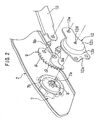
- Fig. 2 is a schematic exploded perspective view illustrating a pinion gear and a sector gear which are components for the height adjusting device shown in Fig. 1;
- Fig. 3 is a schematic sectional view illustrating a combination of a connecting shaft and a supporting pin which are components for the height adjusting device shown in Fig. 1;
- Fig. 4 is a schematic exploded perspective view illustrating the connecting shaft and the supporting pin which are shown in Fig. 3; and
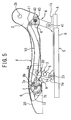
- Fig. 5 is a schematic side view of the height adjusting device of Fig. 1, in which the vehicle seat is in a lifted-up condition.
- Now, a height adjusting device for a vehicle seat, according to the present invention, will be discussed hereinafter with reference to the accompanying drawings. Referring to Fig. 1, a vehicle seat to which the height adjusting device according to the present invention is applied is constructed such that the vehicle seat can be slid forward and rearward through a track mechanism S in an interior of a vehicle. The track mechanism S comprises a pair of lower rail members R spaced apart from each other and mounted on a vehicle floor in parallel with each other (only one lower rail member R is shown in Fig. 1), and a pair of upper rail members A, each of which is slidably supported to a corresponding lower rail member R (only one upper rail member A is shown in Fig. 1).
- The vehicle seat includes a seat cushion frame F. A seat back (not shown) is pivotally supported to the seat cushion frame F through recliner means (not shown). The seat cushion frame F comprises a pair of spaced apart side frame sections 2 (only one
side frame section 2 is shown in Fig. 1), apan frame section 20 arranged between forward portions of the spaced apartside frame sections 2 and attached to the forward portions of theside frame sections 2, and a first pipe-shaped connectingshaft 6 arranged between rearward portions of the spaced apartside frame sections 2 and connected to the rearward portions of the spaced apartside frame sections 2. Theside frame sections 2 are formed so as to extend upwardly at the rearward portions thereof in whichholes 2b (only onehole 2b is shown in Fig. 1) are formed. Ends of a supporting shaft (not shown) for the recliner means are to be inserted in theholes 2b. The seat back includes a pair of spaced apart side frame sections. The spaced apart side frame sections of the seat back are supported to the supporting shaft for the recliner means. Thus, the seat back is pivotally supported to the seat cushion frame F so as to be pivotable forward and rearward relative to the seat cushion. - Each of the upper rail members A of the track mechanism S includes a pair of forward and
rearward brackets second linkage members first linkage members 3 is arranged between corresponding one of theside frame sections 2 of the seat cushion frame F and theforward bracket 1a of corresponding one of the upper rail members A. Similarly, each of thesecond linkage members 4 is arranged between the corresponding one of theside frame sections 2 of the seat cushion F and therearward bracket 1b of the corresponding one of the upper rail members A. Thefirst linkage members 3 are coupled through a second connectingshaft 5 to each other. Similarly, thesecond linkage members 4 are coupled through the first connectingshaft 6 to each other. - The
first linkage members 3 are formed into substantially linear shapes and supported at one ends thereof to theside frame sections 2 by supportingpins 30 and at the other ends thereof to theforward bracket 1a of the upper rail members A by supportingpins 31. Thefirst linkage members 3 are connected at substantially middle regions thereof to each other through the second connectingshaft 5. Theside frame sections 2 of the seat cushion frame F are formed at lower surfaces thereof withnotches 2a which allow the second connectingshaft 5 to be moved synchronously with pivotal movement of thefirst linkage members 3. Each of thenotches 2a is formed into a substantially circular arc-shape. - Each of the
second linkage members 4 is formed into a substantially L-shape. Thesecond linkage members 4 are coupled at substantially middle portions thereof to theside frame sections 2 by supportingpins 40 that project from both ends of the first connectingshaft 6. One ends of thesecond linkage members 4 are connected to therearward brackets 1b of the upper rail members A by supportingpins 41. - The height adjusting device for the vehicle seat further includes an
operating knob 7 having a rotatingshaft 7a and mounted on an outer surface of the one of theside frame sections 2 with the rotatingshaft 7a penetrating through theside frame section 2 and projecting into the seat cushion frame F, apinion gear 8 arranged within an inside of the seat cushion frame F and mounted on the rotatingshaft 7a of theoperating knob 7 that is penetrated inward of the seat cushion frame F through theside frame section 2, asector gear 9 rotatably supported to theside frame section 2 by a supportingpin 9a and meshed with thepinion gear 8, and alinkage rod 10 arranged between thesector gear 9 and one of thesecond linkage members 4 that is arranged on the side of theside frame 2 to which theoperating knob 7 is mounted. - In the illustrated embodiment, as the
operating knob 7, an operating knob that is of a dial-type is employed. Referring to Fig. 2, theoperating knob 7 includes a body supporting the rotatingshaft 7a and amounting section 7b of a plate shape, and is arranged on the outer surface of theside frame section 2 with themounting section 7b being attached onto the outer surface of theside frame section 2 and with the rotatingshaft 7a being penetrated through theside frame section 2. The operating knob body is constructed so as to be rotatable relative to themounting section 7b. - The
sector gear 9 is rotatably supported at a base portion thereof to theside frame section 2 by the supportingpin 9a and coupled at a portion thereof that is offset from the supportingpin 9a, to one end of thelinkage rod 10 by a supportingpin 9b. As shown in Fig. 1, the other end of thelinkage rod 10 is coupled to an upper end of the one of thesecond linkage members 4 by a supportingpin 11. - As shown in Fig. 2, a
gear cover 12 for covering thepinion gear 8 and thesector gear 9 is provided. Thegear cover 12 comprises abase portion 12a, a substantially cylindrical-shaped portion 12b projecting laterally from thebase portion 12a, and atop portion 12c lying on the substantially cylindrical-shaped portion 12b and extending laterally from the substantially cylindrical-shaped portion 12b. Thetop portion 12c is formed with afirst hole 12d and asecond hole 12e in which the rotatingshaft 7a of theoperating knob 7 and the supportingpin 9a of thesector gear 9 are respectively inserted. - The
gear cover 12 is secured on an inner surface of theside frame section 2 with the cylindrical-shaped portion 12b andtop portion 12c covering thepinion gear 8 and thesector gear 9, with thebase portion 12a being mounted on the inner surface of theside frame section 2, and with the first andsecond holes gear cover 12 receiving the rotatingshaft 7a of theoperating knob 7 and the supportingpin 9a of thesector gear 9, respectively. Thus, thepinion gear 8 and thesector gear 9 are arranged between theside frame section 2 and thegear cover 12 so as not to be exposed. In addition, the rotatingshaft 7a of theoperating knob 7 and the supportingshaft 9a of thesector gear 9 are supported by both theside frame section 2 and thegear cover 12 at their opposite ends. - Referring now to Fig. 3, inner end portions of the supporting pins 40 (only one supporting
pin 40 is shown in Fig. 3) for the first connectingshaft 6 are inserted through thesecond linkage members 4 in the ends of the first connectingshaft 6 and welded to thesecond linkage members 4. Outer end portions of the supportingpins 40 are penetrated through theside frame sections 2. - Referring to Fig. 4, each of the supporting pins 40 (only one supporting
pin 40 is shown in Fig. 4) includes acircumferential flange portion 40a provided between theinner end portion 40b extending inwardly from thecircumferential flange portion 40a and inserted in corresponding one of the ends of the first connectingshaft 6 through corresponding one of thesecond linkage members 4, and the outer end portion extending outwardly from thecircumferential flange portion 40a and penetrating through corresponding one of theside frame sections 2. The outer end portion of the supportingpin 40 comprises alarge diameter region 40c and a relativelysmall diameter region 40d. Thesmall diameter region 40d of the supportingpin 40 is to be riveted over after the outer end portion of the supportingpin 40 is penetrated through theside frame section 2. - In order to cause the outer end portion of the supporting
pin 40 to be securely born to the correspondingside frame section 2, afirst washer 42, abearing collar 43, abush 44, and asecond washer 45 are employed. Thebearing collar 43 comprises aboss portion 43a and a pair of protrudingportions 43b laterally protruding in directions opposite to each other from theboss portion 43a. The bearingcollar 43 is mounted on the inner surface of theside frame section 2 with theboss portion 43a being fitted in a hole of theside frame section 2 and with the protrudingportions 43b being welded to theside frame section 2. - Now, a procedure for connecting an end of the first connecting
shaft 6 to the correspondingside frame section 2 by the supportingpin 40 will be discussed in greater detail hereinafter. First of all, theinner end portion 40b of the supportingpin 40 is penetrated through thesecond linkage member 4 in such a manner that thecircumferential flange portion 40a of the supportingpin 40 is applied onto an outer surface of thesecond linkage member 4. Then, thecircumferential flange portion 40a of the supportingpin 40 is welded onto the outer surface of thesecond linkage member 4 by projection welding (see Fig. 3). - The
inner end portion 40b of the supportingpin 40 is then fitted into the end of the first connectingshaft 6. The outer end portion of the supportingpin 40 is inserted through thefirst washer 42 and theboss portion 43a of the bearingcollar 43 and then inserted through the hole of theside frame section 2. - The
bush 44 is then mounted on the outer end portion of the supportingpin 40 that has been projected outward of theside frame 2, and fitted into theboss portion 43a of the bearingcollar 43 through the hole of theside frame section 2. Thesecond washer 45 is then mounted on the outer end portion of the supportingpin 40. Thereafter, thesmall diameter portion 40d of the supportingpin 40 is riveted over thesecond washer 45 as a rivetedportion 40e (see Fig. 3). Moreover, the first connectingshaft 6 is welded to thesecond linkage member 4. The other end of the first connectingshaft 6 is connected to the other of theside frame sections 2 in the same manner as the one end of the first connectingshaft 6 is connected to the one of theside frame sections 2. Thus, the first connectingshaft 6 is rotatable relative to theside frame sections 2. - As described above, the
inner end portions 40b of the supportingpins 40 are fitted in the ends of the first connectingshaft 6 through thesecond linkage members 4 and welded to thesecond linkage members 4, and the outer end portions of the supporting pins are connected to theside frame sections 2. Thus, the supportingpins 40 cab be easily coupled to theside frame sections 2 and the ends of the first connectingshaft 6 in such a manner that the supportingpins 40 act as supports for the pivotal movement of thesecond linkage members 4. - In the height adjusting device constructed as discussed above, in a condition where the vehicle seat is lowered as shown in Fig. 1, the
linkage rod 10 is thrust rearward by thesector gear 9 and the first andsecond linkage members - In this condition, when the body of the operating
knob 7 is rotated in a predetermined direction, thepinion gear 8 is simultaneously rotated. Synchronously with the rotation of thepinion gear 8, thesector gear 9 is rotated about the supportingpin 9a in a counterclockwise direction in Fig. 1, whereby thelinkage rod 10 is drawn forward. Simultaneously with the forward movement of thelinkage rod 10, thesecond linkage members 4 are rotated around the supportingpins 41 so as to operatively stand up and thefirst linkage members 3 are also rotated around the supportingpins 31 so as to operatively stand up. Thus, the vehicle seat is lifted up as shown in Fig. 5. - The
second linkage members 4 are supported to theside frame sections 2 through the supportingpins 40 coupled to the ends of the first connectingshaft 6, so that the first andsecond linkage members pinion gear 8 and thesector gear 9 are arranged between theside frame section 2 and thegear cover 12 so as to be covered by thegear cover 12, so that any foreign materials can be prevented from being caught between thepinion gear 8 and thesector gear 9. In addition, therotating shaft 7a of the operatingknob 7 that supports thepinion gear 8, and the supportingpin 9a supporting thesector gear 9 are supported by both theside frame section 2 and thegear cover 12 at their opposite ends, so that thesector gear 9 can be securely prevented from being deflected, namely, producing runout. Therefore, thesector gear 9 can be stably and positively rotated by the pinion gear.
Claims (1)
- A height adjusting device for adjusting a height of a vehicle seat, said vehicle seat including a seat cushion frame supported through first and second pairs of spaced apart brackets, said seat cushion frame having a pair of first and second spaced apart side frame sections, said height adjusting device comprising first and second pairs of linkage members, said first pair of linkage members being bridged between first portions of said side frame sections and said first pair of said spaced apart brackets, said second pair of linkage members being bridged between second portions of said side frame sections and said second pair of said spaced apart brackets, a first connecting shaft interconnecting said second pair of linkage members, a second connecting shaft interconnecting said first pair of linkage members, an operating knob attached to said first side frame section, said operating knob having a rotating shaft that is projected inward of said seat cushion frame through said first side frame section, a pinion gear arranged inside said seat cushion frame and mounted on said rotating shaft of said operating knob, a sector gear pivotally supported to said first side frame section by a supporting pin, and a linkage rod coupled at one end thereof to a portion of said sector gear that is offset from said supporting pin of said sector gear, and coupled at the other end thereof to one of said second linkage members, characterised in that said height adjusting device further includes a cover covering said pinion gear and said sector gear, said cover being fixed onto an inner surface of said first side frame section, ends of said rotating shaft and supporting pin being supported to said cover, whereby said rotating shaft and said supporting pin are supported by both said first side frame section and said cover.
Applications Claiming Priority (2)
| Application Number | Priority Date | Filing Date | Title |
|---|---|---|---|
| JP2003115956A JP2006182039A (en) | 2003-04-21 | 2003-04-21 | Height adjusting device for car seat |
| PCT/JP2004/005718 WO2004094180A1 (en) | 2003-04-21 | 2004-04-21 | Height adjusting device for car seat |
Publications (3)
| Publication Number | Publication Date |
|---|---|
| EP1621393A1 true EP1621393A1 (en) | 2006-02-01 |
| EP1621393A4 EP1621393A4 (en) | 2009-09-30 |
| EP1621393B1 EP1621393B1 (en) | 2011-12-14 |
Family
ID=33307968
Family Applications (1)
| Application Number | Title | Priority Date | Filing Date |
|---|---|---|---|
| EP04728697A Expired - Lifetime EP1621393B1 (en) | 2003-04-21 | 2004-04-21 | Height adjusting device for car seat |
Country Status (4)
| Country | Link |
|---|---|
| US (1) | US7278686B2 (en) |
| EP (1) | EP1621393B1 (en) |
| JP (1) | JP2006182039A (en) |
| WO (1) | WO2004094180A1 (en) |
Cited By (1)
| Publication number | Priority date | Publication date | Assignee | Title |
|---|---|---|---|---|
| CZ303075B6 (en) * | 2010-12-29 | 2012-03-21 | Technická univerzita v Liberci | Seat, especially automobile or working machine driver seat |
Families Citing this family (30)
| Publication number | Priority date | Publication date | Assignee | Title |
|---|---|---|---|---|
| CN100506595C (en) * | 2004-09-17 | 2009-07-01 | 爱信精机株式会社 | mobile device |
| EP1894769B1 (en) | 2005-03-31 | 2012-08-29 | TS Tech Co., Ltd. | Seat height adjustment device for automobile |
| US7654615B2 (en) * | 2005-09-15 | 2010-02-02 | Intier Automotive Seating Systems Gmbh | Seat assembly having a seat cushion rocker mechanism |
| JP4883441B2 (en) * | 2006-05-19 | 2012-02-22 | テイ・エス テック株式会社 | Automotive seat height adjustment device |
| JP4900916B2 (en) * | 2006-07-07 | 2012-03-21 | 株式会社タチエス | Vehicle seat height mechanism |
| US7594635B2 (en) * | 2007-03-28 | 2009-09-29 | Aisin Seiki Kabushiki Kaisha | Seat sliding apparatus for vehicle |
| DE102007029167B3 (en) * | 2007-06-25 | 2008-10-09 | Lear Corp., Southfield | Vehicle seat, has clamp connected to sector gear wheel and engaged to pivot, where pivot is connected with wheel and is brought into outside engagement with clamp during movement of backrest |
| KR100885096B1 (en) | 2007-08-14 | 2009-02-20 | 계양전기 주식회사 | Car seat height adjustment device |
| WO2012049726A1 (en) | 2010-10-12 | 2012-04-19 | テイ・エス テック株式会社 | Vehicle seat |
| JP5548058B2 (en) * | 2010-07-12 | 2014-07-16 | 本田技研工業株式会社 | Control device for vehicle seat |
| US8616636B2 (en) * | 2011-02-17 | 2013-12-31 | Tachi-S Co., Ltd. | Vehicle seat |
| DE102011001638A1 (en) * | 2011-03-29 | 2012-10-04 | C. Rob. Hammerstein Gmbh & Co. Kg | Undercarriage for a motor vehicle seat |
| JP2012254777A (en) * | 2011-05-19 | 2012-12-27 | Shiroki Corp | Seat lifter |
| US9352666B2 (en) * | 2011-08-10 | 2016-05-31 | Ts Tech Co., Ltd. | Vehicle seat |
| US20140224553A1 (en) * | 2011-08-10 | 2014-08-14 | Ts Tech Co., Ltd. | Load measurement sensor support structure |
| CN104284799B (en) | 2012-05-07 | 2017-03-22 | 约翰逊控制技术公司 | Seat adjustment device for vertical adjustment of vehicle seat |
| DE102012013208B4 (en) | 2012-05-07 | 2019-07-25 | Adient Luxembourg Holding S.À R.L. | Seat part of a vehicle seat |
| US9878640B2 (en) * | 2012-09-12 | 2018-01-30 | Ts Tech Co., Ltd. | Vehicle seat and method for manufacturing same |
| BR112015010748A2 (en) | 2012-11-16 | 2017-07-11 | Ts Tech Co Ltd | vehicle seat |
| JP6054713B2 (en) * | 2012-11-16 | 2016-12-27 | テイ・エス テック株式会社 | Vehicle seat |
| US20150291072A1 (en) | 2012-11-16 | 2015-10-15 | Ts Tech Co., Ltd. | Vehicle seat |
| JP6559496B2 (en) * | 2015-07-31 | 2019-08-14 | トヨタ紡織株式会社 | Vehicle seat frame |
| KR101683397B1 (en) * | 2015-09-25 | 2016-12-06 | 주식회사다스 | apparatus for driving height link of seat for car |
| KR101827130B1 (en) * | 2016-07-06 | 2018-02-07 | 현대자동차주식회사 | Height adjusting apparatus of vehicle seat |
| US10766383B2 (en) * | 2016-07-28 | 2020-09-08 | Tachi-S Co., Ltd. | Vehicle seat |
| DE102017109145B3 (en) * | 2017-04-28 | 2018-05-09 | Schaeffler Technologies AG & Co. KG | Gear arrangement for an actuator device for height adjustment of a vehicle body |
| JP6977476B2 (en) * | 2017-10-24 | 2021-12-08 | トヨタ紡織株式会社 | Cushion frame |
| JP7125903B2 (en) * | 2019-02-20 | 2022-08-25 | シロキ工業株式会社 | Vehicle seat lifting device |
| KR20240016050A (en) * | 2022-07-28 | 2024-02-06 | 현대자동차주식회사 | Seat adjust apparatus for mobility |
| CN119768307A (en) | 2023-08-02 | 2025-04-04 | 提爱思科技股份有限公司 | Vehicle seat |
Family Cites Families (10)
| Publication number | Priority date | Publication date | Assignee | Title |
|---|---|---|---|---|
| JPS61249844A (en) * | 1985-04-27 | 1986-11-07 | Ikeda Bussan Co Ltd | Seat for vehicles |
| FR2591875B1 (en) * | 1985-12-23 | 1988-04-08 | Cousin Cie Ets A & M Freres | STANDARD MODULE DEVICE FOR ADJUSTING THE HEIGHT OF A SEAT |
| KR960004301B1 (en) * | 1986-03-03 | 1996-03-30 | 후지 기꼬오 가부시끼가이샤 | Car seat |
| US5203532A (en) * | 1990-09-18 | 1993-04-20 | Fuji Kiko Co., Ltd. | Seat adjuster |
| DE4224458A1 (en) * | 1992-07-24 | 1994-01-27 | Brose Fahrzeugteile | Seat cushion adjustment for vehicle seat - has mechanical drive providing movement between two extreme positions |
| GB2303059B (en) * | 1995-07-06 | 1997-08-27 | Fuji Kiko Kk | Seat lifter for motor vehicles |
| JP4499856B2 (en) * | 1999-11-11 | 2010-07-07 | 富士機工株式会社 | Seat height adjustment device |
| JP2001295897A (en) * | 2000-04-13 | 2001-10-26 | Koyo Seiko Co Ltd | Planetary gear set |
| JP2001304350A (en) * | 2000-04-19 | 2001-10-31 | Koyo Seiko Co Ltd | Planetary gear set |
| JP2002010860A (en) * | 2000-06-30 | 2002-01-15 | Delta Kogyo Co Ltd | Seat lifter structure |
-
2003
- 2003-04-21 JP JP2003115956A patent/JP2006182039A/en active Pending
-
2004
- 2004-04-21 US US10/554,128 patent/US7278686B2/en not_active Expired - Fee Related
- 2004-04-21 EP EP04728697A patent/EP1621393B1/en not_active Expired - Lifetime
- 2004-04-21 WO PCT/JP2004/005718 patent/WO2004094180A1/en not_active Ceased
Cited By (1)
| Publication number | Priority date | Publication date | Assignee | Title |
|---|---|---|---|---|
| CZ303075B6 (en) * | 2010-12-29 | 2012-03-21 | Technická univerzita v Liberci | Seat, especially automobile or working machine driver seat |
Also Published As
| Publication number | Publication date |
|---|---|
| EP1621393B1 (en) | 2011-12-14 |
| US20070063570A1 (en) | 2007-03-22 |
| JP2006182039A (en) | 2006-07-13 |
| EP1621393A4 (en) | 2009-09-30 |
| US7278686B2 (en) | 2007-10-09 |
| WO2004094180A1 (en) | 2004-11-04 |
Similar Documents
| Publication | Publication Date | Title |
|---|---|---|
| EP1621393B1 (en) | Height adjusting device for car seat | |
| EP1621392B1 (en) | Height-adjusting device for automobile seat | |
| EP2062772B1 (en) | Automobile seat with height adjusting device | |
| US8141952B2 (en) | Adjustable bolster assembly | |
| KR102235731B1 (en) | Seat tilting device with adjustable height | |
| US20120261963A1 (en) | Vehicle Seat with a Pivotably Connected Linking Member | |
| JP5420192B2 (en) | Vehicle seat | |
| EP1955889A2 (en) | Swivel seat and suspension apparatus | |
| US6340208B1 (en) | Motor vehicle seat, in particular back seat | |
| JP2008302921A6 (en) | Vehicle seat | |
| US20060061197A1 (en) | Fitting system for a vehicle seat | |
| JPH08244505A (en) | Seat support device | |
| US4181353A (en) | Vehicle seat | |
| JP6488727B2 (en) | Vehicle seat | |
| EP1491390A1 (en) | Seat for vehicle | |
| JP2015003573A (en) | Vehicular seat | |
| US4799733A (en) | Seat structure having a pivotable backrest and in particular a front seat structure of a motor vehicle | |
| JP2000189266A (en) | Sheet adjustment device | |
| JP3750522B2 (en) | Vehicle seat | |
| KR102960478B1 (en) | Leg rest for vehicle | |
| JPH07315084A (en) | Seat cushion length variable mechanism | |
| EP0778805B1 (en) | Seat height adjustment mechanism for a vehicle seat | |
| EP1780071B1 (en) | Motor vehicle seat having a tilt and height adjustment device | |
| JP4899204B2 (en) | Automotive seat height adjustment device | |
| JP2024036619A (en) | vehicle seat |
Legal Events
| Date | Code | Title | Description |
|---|---|---|---|
| PUAI | Public reference made under article 153(3) epc to a published international application that has entered the european phase |
Free format text: ORIGINAL CODE: 0009012 |
|
| 17P | Request for examination filed |
Effective date: 20051118 |
|
| AK | Designated contracting states |
Kind code of ref document: A1 Designated state(s): DE FR GB |
|
| DAX | Request for extension of the european patent (deleted) | ||
| RBV | Designated contracting states (corrected) |
Designated state(s): DE FR GB |
|
| A4 | Supplementary search report drawn up and despatched |
Effective date: 20090831 |
|
| 17Q | First examination report despatched |
Effective date: 20100625 |
|
| GRAP | Despatch of communication of intention to grant a patent |
Free format text: ORIGINAL CODE: EPIDOSNIGR1 |
|
| GRAS | Grant fee paid |
Free format text: ORIGINAL CODE: EPIDOSNIGR3 |
|
| GRAA | (expected) grant |
Free format text: ORIGINAL CODE: 0009210 |
|
| AK | Designated contracting states |
Kind code of ref document: B1 Designated state(s): DE FR GB |
|
| REG | Reference to a national code |
Ref country code: GB Ref legal event code: FG4D |
|
| REG | Reference to a national code |
Ref country code: DE Ref legal event code: R096 Ref document number: 602004035673 Country of ref document: DE Effective date: 20120223 |
|
| PLBE | No opposition filed within time limit |
Free format text: ORIGINAL CODE: 0009261 |
|
| STAA | Information on the status of an ep patent application or granted ep patent |
Free format text: STATUS: NO OPPOSITION FILED WITHIN TIME LIMIT |
|
| 26N | No opposition filed |
Effective date: 20120917 |
|
| REG | Reference to a national code |
Ref country code: DE Ref legal event code: R097 Ref document number: 602004035673 Country of ref document: DE Effective date: 20120917 |
|
| REG | Reference to a national code |
Ref country code: FR Ref legal event code: PLFP Year of fee payment: 12 |
|
| PGFP | Annual fee paid to national office [announced via postgrant information from national office to epo] |
Ref country code: GB Payment date: 20150420 Year of fee payment: 12 Ref country code: DE Payment date: 20150421 Year of fee payment: 12 |
|
| PGFP | Annual fee paid to national office [announced via postgrant information from national office to epo] |
Ref country code: FR Payment date: 20150421 Year of fee payment: 12 |
|
| REG | Reference to a national code |
Ref country code: DE Ref legal event code: R119 Ref document number: 602004035673 Country of ref document: DE |
|
| GBPC | Gb: european patent ceased through non-payment of renewal fee |
Effective date: 20160421 |
|
| REG | Reference to a national code |
Ref country code: FR Ref legal event code: ST Effective date: 20161230 |
|
| PG25 | Lapsed in a contracting state [announced via postgrant information from national office to epo] |
Ref country code: DE Free format text: LAPSE BECAUSE OF NON-PAYMENT OF DUE FEES Effective date: 20161101 Ref country code: GB Free format text: LAPSE BECAUSE OF NON-PAYMENT OF DUE FEES Effective date: 20160421 Ref country code: FR Free format text: LAPSE BECAUSE OF NON-PAYMENT OF DUE FEES Effective date: 20160502 |