EP1621358A1 - A Printing Apparatus - Google Patents
A Printing Apparatus Download PDFInfo
- Publication number
- EP1621358A1 EP1621358A1 EP05106852A EP05106852A EP1621358A1 EP 1621358 A1 EP1621358 A1 EP 1621358A1 EP 05106852 A EP05106852 A EP 05106852A EP 05106852 A EP05106852 A EP 05106852A EP 1621358 A1 EP1621358 A1 EP 1621358A1
- Authority
- EP
- European Patent Office
- Prior art keywords
- print head
- printing
- motor
- printing medium
- electrical signal
- Prior art date
- Legal status (The legal status is an assumption and is not a legal conclusion. Google has not performed a legal analysis and makes no representation as to the accuracy of the status listed.)
- Withdrawn
Links
Images




Classifications
-
- B—PERFORMING OPERATIONS; TRANSPORTING
- B41—PRINTING; LINING MACHINES; TYPEWRITERS; STAMPS
- B41J—TYPEWRITERS; SELECTIVE PRINTING MECHANISMS, i.e. MECHANISMS PRINTING OTHERWISE THAN FROM A FORME; CORRECTION OF TYPOGRAPHICAL ERRORS
- B41J29/00—Details of, or accessories for, typewriters or selective printing mechanisms not otherwise provided for
- B41J29/38—Drives, motors, controls or automatic cut-off devices for the entire printing mechanism
- B41J29/393—Devices for controlling or analysing the entire machine ; Controlling or analysing mechanical parameters involving printing of test patterns
-
- B—PERFORMING OPERATIONS; TRANSPORTING
- B41—PRINTING; LINING MACHINES; TYPEWRITERS; STAMPS
- B41J—TYPEWRITERS; SELECTIVE PRINTING MECHANISMS, i.e. MECHANISMS PRINTING OTHERWISE THAN FROM A FORME; CORRECTION OF TYPOGRAPHICAL ERRORS
- B41J11/00—Devices or arrangements of selective printing mechanisms, e.g. ink-jet printers or thermal printers, for supporting or handling copy material in sheet or web form
- B41J11/36—Blanking or long feeds; Feeding to a particular line, e.g. by rotation of platen or feed roller
- B41J11/42—Controlling printing material conveyance for accurate alignment of the printing material with the printhead; Print registering
- B41J11/44—Controlling printing material conveyance for accurate alignment of the printing material with the printhead; Print registering by devices, e.g. program tape or contact wheel, moved in correspondence with movement of paper-feeding devices, e.g. platen rotation
-
- B—PERFORMING OPERATIONS; TRANSPORTING
- B41—PRINTING; LINING MACHINES; TYPEWRITERS; STAMPS
- B41J—TYPEWRITERS; SELECTIVE PRINTING MECHANISMS, i.e. MECHANISMS PRINTING OTHERWISE THAN FROM A FORME; CORRECTION OF TYPOGRAPHICAL ERRORS
- B41J2/00—Typewriters or selective printing mechanisms characterised by the printing or marking process for which they are designed
- B41J2/005—Typewriters or selective printing mechanisms characterised by the printing or marking process for which they are designed characterised by bringing liquid or particles selectively into contact with a printing material
- B41J2/01—Ink jet
- B41J2/015—Ink jet characterised by the jet generation process
- B41J2/04—Ink jet characterised by the jet generation process generating single droplets or particles on demand
- B41J2/045—Ink jet characterised by the jet generation process generating single droplets or particles on demand by pressure, e.g. electromechanical transducers
- B41J2/04501—Control methods or devices therefor, e.g. driver circuits, control circuits
- B41J2/04586—Control methods or devices therefor, e.g. driver circuits, control circuits controlling heads of a type not covered by groups B41J2/04575 - B41J2/04585, or of an undefined type
-
- B—PERFORMING OPERATIONS; TRANSPORTING
- B41—PRINTING; LINING MACHINES; TYPEWRITERS; STAMPS
- B41J—TYPEWRITERS; SELECTIVE PRINTING MECHANISMS, i.e. MECHANISMS PRINTING OTHERWISE THAN FROM A FORME; CORRECTION OF TYPOGRAPHICAL ERRORS
- B41J2/00—Typewriters or selective printing mechanisms characterised by the printing or marking process for which they are designed
- B41J2/315—Typewriters or selective printing mechanisms characterised by the printing or marking process for which they are designed characterised by selective application of heat to a heat sensitive printing or impression-transfer material
- B41J2/32—Typewriters or selective printing mechanisms characterised by the printing or marking process for which they are designed characterised by selective application of heat to a heat sensitive printing or impression-transfer material using thermal heads
Definitions
- the present invention relates to a printing apparatus and a method for control thereof, the printing apparatus comprising a print head and an idle roller for feeding a printing medium to the print head.
- a thermal printing apparatus is an apparatus which forms an image by heating a thermal print head contacting an ink ribbon which in turn contacts a printing medium (such as paper, acetate or the like) and transfers ink onto the printing medium.
- the thermal printing apparatus may also form an image by heating the thermal print head which contacts the printing medium on which a heat reacting ink layer is located.
- the colour of the heat reacting ink is predetermined.
- the thermal print head heats the printing medium for a predetermined time period.
- the printing operation is performed by heating the medium or ejecting ink from the print head at a predetermined time period regardless of the transfer speed of the printing medium.
- the supply speed of the printing medium is changed by an external influence such as a load change on the printing medium, the printing resolution cannot be exactly maintained.
- the present invention relates to a printing apparatus and a method for control thereof, the printing apparatus comprising a print head and an idle roller for feeding a printing medium to the print head.
- a printing apparatus is characterised by means operable to detect movement of the idle roller wherein said printing is performed in accordance with said movement.
- a method according to the present invention is characterised by detecting the movement of the idle roller and performing the printing in accordance with said movement.
- the thermal printing apparatus (sometimes referred to as the thermal transfer image forming apparatus) comprises a thermal print head 100, a thermal print head nozzle 110, a platen roller 120, a motor 130, a driving roller 140, an idle roller 150, an encoder 160, and a media sensor 170.
- the thermal print head 100 heats a printing medium for a predetermined heating time period.
- the thermal print head nozzle 110 supplies ink required for printing to the platen roller 120.
- the platen roller 120 supports the printing medium so that the printing medium is fed between the platen roller 120 and the thermal print head 100.
- the platen roller 120 is opposite the thermal print head 100 and rotates to transfer the image to the printing medium.
- the motor 130 supplies the printing medium to the thermal print head 100.
- the driving roller 140 engages with the motor 130 and rotates, thus feeding the printing medium through the printing apparatus.
- the idle roller 150 engages with the driving roller 140 and rotates.
- the printing medium is fed between the idle roller 150 and the driving roller 140.
- the encoder 160 is attached to the idle roller 150 and converts the operation of the idle roller 150 into an electrical signal and outputs the electrical signal.
- the media sensor 170 senses the position of the printing medium to be printed.
- the thermal print head 100 may perform the printing operation by heating first and second sides of the printing medium, respectively. For example, when an image printing operation is performed on the first side of the printing medium, the thermal print head 100 is placed at position C. However, when the image printing operation is performed on the second side of the printing medium, the thermal print head 100 rotates along with the platen roller 120 to be placed to position D.
- the apparatus for controlling the thermal print head comprises an idle roller 200, an encoder 210, a counter 220, a thermal print head 230, a motor controller 240, and a motor 250.
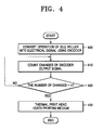
- the apparatus of Figure 2 will now be described with reference to the flowchart of Figure 4.
- the encoder 210 is attached to the idle roller 200 and converts the operation of the idle roller 200 into an electrical signal at step 400.
- the counter 220 counts the number of changes of the output signal of the encoder 210 at step 410 and compares the number of changes of the output signal of the encoder 210 with a heating period n at step 420.
- the heating period n is established so as to synchronise the heating time of the thermal print head 230 with the output signal of the encoder 210.
- the counter 220 Whenever the number of changes reaches the heating time n, the counter 220 outputs a heat signal to commence heating of the thermal print head 230.
- the thermal print head 230 heats the printing medium in response to the heat signal at step 430.
- the counter 220 counts the rising or falling edges of the output signal of the encoder 210 or a portion in which the output signal of the encoder 210 is a predetermined value when the output signal of the encoder 210 is a square wave. This is the change of the output signal of the encoder 210.
- the output signal of the encoder 210 is a sinusoidal wave
- the change of the output signal, which is counted occurs when the sinusoidal wave is at a maximum or minimum value.
- the motor 250 feeds the printing medium to the thermal print head 230.
- the operation of the motor 250 is controlled by the motor controller 240.
- the motor controller of Figure 3 comprises a reference value setting portion 300, a motor 250, a speed calculating portion 320 and a controlling portion 330.
- the operation of the motor controller 240 shown in Figure 3 will be described with reference to the flowchart of Figure 8.
- the reference value setting portion 300 establishes a reference value V r for the motor speed for controlling the operation of the motor 250 at step 800.
- the speed calculating portion 320 calculates the current speed V of the idle roller 220 using the output signal of the encoder 210, that is, the electrical signal generated by the encoder 210 at step 810.
- the speed V is calculated by the following method. Firstly, changes of the output signal of the encoder 210 are counted. Then the number of changes counted per predetermined control period is multiplied by a unit distance which the idle roller 200 rotates between changes of the output signal of the encoder 210. The distance moved by the idle roller 200 is then calculated. The calculated distance is divided by the time taken for counting the changes of the output signal of the encoder 210. Thus, the speed of the idle roller 200 is calculated.
- the output signal of the encoder 210 is a square wave
- the change of the output signal of the encoder 210 may be either a rising or falling edge of the output signal of the encoder 210 or a portion in which the output signal of the encoder 210 has a predetermined value.
- the output signal of the encoder 210 is a sinusoidal wave
- the change of the output signal of the encoder 210 is a portion in which the output signal of the encoder 210 is a maximum or minimum value.
- the controlling portion 330 determines whether the reference value V r of the motor speed output from the reference value setting portion 300 is the same as the current speed V of the idle roller 200 output from the speed calculating portion 320. This is done at step 820. If the controlling portion 330 compares the current speed V of the idle roller 200 with the motor speed reference value V r and it is determined that the current speed V is in a predetermined range of errors, it is determined that the current speed V of the idle roller 200 is the same as the motor speed reference value V r .
- the controlling portion 330 determines whether the current speed V of the idle roller 200 is less than the motor speed reference value V r at step 830. If the current speed V of the idle roller 200 is less than the motor speed reference value V r , the controlling portion 330 increases the amount of current supplied to the motor 250 so that the speed of the motor 250 increases at step 840. If the current speed V of the idle roller 200 is greater than the motor speed reference value V r , the controlling portion 330 decreases the current supplied to the motor 250 so that the speed of the motor 250 decreases.
- the controlling portion 330 may be a proportional (P) integral (I) derivative (D) (PID), PI, P, an adaptive controller or any other suitable control device.
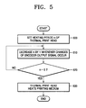
- the heating period n at which the printing medium of the thermal print head 230 is heated is established at step500. Changes of the output signal of the encoder 210 are sensed and n is decreased by 1 whenever a change of the output signal of the encoder 210 occurs at step 510. In this case, a down counter may be used.
- step 520 It is determined whether n is equal to 0 at step 520. If it is determined that n is not equal to 0, step 510 is repeatedly performed until n becomes 0. If it is determined that n is equal to 0, the thermal print head 230 heats the printing medium at step 530.
- the thermal print head 230 establishes the heating period as 2. Therefore, the thermal print head 230 heats the printing medium whenever the number of rising edges of the output signal of the encoder 210 counted by the counter 220 is 2.
- the thermal print head 230 establishes the heating period as 2. Therefore, the thermal print head 230 heats the printing medium whenever the number of maximum or minimum values of the output signal of the encoder 210 counted by the counter 220 is 2. This is determined when the differential value of the sinusoidal wave is 0.
- the apparatus of Figure 9 comprises a pickup roller 900, a driving roller 910, an idle roller 920, an encoder 930, and discharging rollers 940 and 950.
- the encoder 930 is attached to the idle roller 920 and converts the movement of the idle roller 920 into an electrical signal and outputs the electrical signal.
- An ink-jet print head (not shown) is synchronized with the encoder output signal and ejects ink onto the printing medium.
- the operation of a motor (not shown) for driving the driving roller 910 is controlled using the output signal of the encoder 930.
- the apparatus of Figure 10 comprises a pickup roller 1000, drive rollers 1010 and 1020, a driving roller 1030, an idle roller 1040, an encoder 1050, and discharging rollers 1060 and 1070.
- the encoder 1050 is attached to the idle roller 1040 and converts the operation of the idle roller 1040 into an electrical signal and outputs the electrical signal.
- An ink-jet print head (not shown) is synchronized with the encoder output signal and ejects ink onto the printing medium.
- the operation of a motor (not shown) for driving the driving roller 1030 may also be controlled using the output signal of the encoder 1050.
- thermal printing apparatus using the thermal print head and the ink-jet image forming apparatus have been described, an apparatus for controlling a print head of a printing apparatus using an encoder according to an exemplary embodiment of the present invention can be applied to all line printing apparatuses.
- the invention can also be embodied as computer readable codes on a computer readable recording medium.
- the computer readable recording medium is any data storage device that can store data which can be thereafter read by a computer system.
- the computer readable recording medium comprises read-only memory (ROM), random-access memory (RAM), CD-ROMs, magnetic tapes, floppy disks, optical data storage devices, and carrier waves (such as data transmission through the Internet).
- ROM read-only memory
- RAM random-access memory
- CD-ROMs compact discs
- magnetic tapes magnetic tapes
- floppy disks optical data storage devices
- carrier waves such as data transmission through the Internet
- a time period at which the print head prints an image on the printing medium is synchronized with an encoder output signal attached to an idle roller such that a predetermined printing interval is maintained and an exact printing resolution is provided even when a printing medium input speed is changed by an external load change.
- a movement speed of the printing medium is calculated by using the output signal of the encoder attached to the idle roller and changes of a motor speed is compensated in a real-time by using a controller such that the speed at which the printing medium is supplied is maintained.
Landscapes
- Electronic Switches (AREA)
- Handling Of Sheets (AREA)
Abstract
Provided are a method and an apparatus for controlling a print head (110) of an image forming apparatus by using an encoder (160) in which the operation of a motor (130) is controlled by using an electrical signal attached to an idle roller (150) and a period at which the print head prints an image on a printing medium is synchronized with the electrical signal. The method comprises converting the operation of the idle roller (150) into an electrical signal by using the encoder (160) and outputting the electrical signal, and controlling the print head so that the print head prints an image on the printing medium in response to the electrical signal.
Description
- The present invention relates to a printing apparatus and a method for control thereof, the printing apparatus comprising a print head and an idle roller for feeding a printing medium to the print head.
- A thermal printing apparatus is an apparatus which forms an image by heating a thermal print head contacting an ink ribbon which in turn contacts a printing medium (such as paper, acetate or the like) and transfers ink onto the printing medium. The thermal printing apparatus may also form an image by heating the thermal print head which contacts the printing medium on which a heat reacting ink layer is located. The colour of the heat reacting ink is predetermined. The thermal print head heats the printing medium for a predetermined time period.
- In the above-described line printing apparatus which uses the thermal print head or an ink-jet print head, the printing operation is performed by heating the medium or ejecting ink from the print head at a predetermined time period regardless of the transfer speed of the printing medium. However, if the supply speed of the printing medium is changed by an external influence such as a load change on the printing medium, the printing resolution cannot be exactly maintained.
- The present invention relates to a printing apparatus and a method for control thereof, the printing apparatus comprising a print head and an idle roller for feeding a printing medium to the print head.
- A printing apparatus according to the present invention is characterised by means operable to detect movement of the idle roller wherein said printing is performed in accordance with said movement.
- A method according to the present invention is characterised by detecting the movement of the idle roller and performing the printing in accordance with said movement.
- Additional preferred and/or advantageous features are hereby set forth in claims 2 to 7 appended hereto.
- An embodiment of the present invention will now be described, by way of example only, and with reference to the accompanying drawings in which:
- Figure 1 is a perspective view illustrating a thermal printing apparatus comprising an encoder attached to an idle roller according to an exemplary embodiment of the present invention;
- Figure 2 is a block diagram illustrating an apparatus for controlling a thermal print head by using an encoder according to an exemplary embodiment of the present invention;
- Figure 3 is a detailed block diagram illustrating a motor controller shown in Figure 2 according to an exemplary embodiment of the present invention;
- Figure 4 is a flowchart illustrating a method of controlling a thermal print head by using an encoder according to an exemplary embodiment of the present invention;
- Figure 5 is a detailed flowchart illustrating the method shown in Figure 4;
- Figure 6 is a diagram illustrating an encoder output signal comprising a square wave shape versus printing medium heating time of a thermal print head;
- Figure 7 is a diagram illustrating an encoder output signal comprising a sinusoidal wave shape versus printing time of a thermal print head;
- Figure 8 is a flowchart illustrating a method of controlling a motor by using an encoder attached to an idle roller;
- Figure 9 is a perspective view illustrating a bin-shaped ink-jet image forming apparatus comprising an encoder attached to an idle roller; and
- Figure 10 is a perspective view of a C path type ink-jet image forming apparatus comprising an encoder attached to an idle roller.
- Throughout the drawings, it should be noted that like reference numbers are used to depict the same or similar elements, features and structures.
- Referring to Figure 1, the thermal printing apparatus (sometimes referred to as the thermal transfer image forming apparatus) comprises a
thermal print head 100, a thermalprint head nozzle 110, aplaten roller 120, amotor 130, adriving roller 140, anidle roller 150, anencoder 160, and amedia sensor 170. - The thermal print head 100 heats a printing medium for a predetermined heating time period. The thermal
print head nozzle 110 supplies ink required for printing to theplaten roller 120. Theplaten roller 120 supports the printing medium so that the printing medium is fed between theplaten roller 120 and thethermal print head 100. Theplaten roller 120 is opposite thethermal print head 100 and rotates to transfer the image to the printing medium. - The
motor 130 supplies the printing medium to thethermal print head 100. Thedriving roller 140 engages with themotor 130 and rotates, thus feeding the printing medium through the printing apparatus. Theidle roller 150 engages with thedriving roller 140 and rotates. The printing medium is fed between theidle roller 150 and thedriving roller 140. Theencoder 160 is attached to theidle roller 150 and converts the operation of theidle roller 150 into an electrical signal and outputs the electrical signal. Themedia sensor 170 senses the position of the printing medium to be printed. - In order to print an image on the printing medium using one thermal print head, the
thermal print head 100 may perform the printing operation by heating first and second sides of the printing medium, respectively. For example, when an image printing operation is performed on the first side of the printing medium, thethermal print head 100 is placed at position C. However, when the image printing operation is performed on the second side of the printing medium, thethermal print head 100 rotates along with theplaten roller 120 to be placed to position D. - Referring to Figure 2, the apparatus for controlling the thermal print head comprises an
idle roller 200, anencoder 210, acounter 220, athermal print head 230, amotor controller 240, and amotor 250. The apparatus of Figure 2 will now be described with reference to the flowchart of Figure 4. - The
encoder 210 is attached to theidle roller 200 and converts the operation of theidle roller 200 into an electrical signal atstep 400. Thecounter 220 counts the number of changes of the output signal of theencoder 210 atstep 410 and compares the number of changes of the output signal of theencoder 210 with a heating period n atstep 420. The heating period n is established so as to synchronise the heating time of thethermal print head 230 with the output signal of theencoder 210. - Whenever the number of changes reaches the heating time n, the
counter 220 outputs a heat signal to commence heating of thethermal print head 230. The thermal print head 230 heats the printing medium in response to the heat signal atstep 430. Thecounter 220 counts the rising or falling edges of the output signal of theencoder 210 or a portion in which the output signal of theencoder 210 is a predetermined value when the output signal of theencoder 210 is a square wave. This is the change of the output signal of theencoder 210. When the output signal of theencoder 210 is a sinusoidal wave, the change of the output signal, which is counted, occurs when the sinusoidal wave is at a maximum or minimum value. - The
motor 250 feeds the printing medium to thethermal print head 230. The operation of themotor 250 is controlled by themotor controller 240. - The motor controller of Figure 3 comprises a reference
value setting portion 300, amotor 250, aspeed calculating portion 320 and a controllingportion 330. The operation of themotor controller 240 shown in Figure 3 will be described with reference to the flowchart of Figure 8. - The reference
value setting portion 300 establishes a reference value Vr for the motor speed for controlling the operation of themotor 250 atstep 800. Thespeed calculating portion 320 calculates the current speed V of theidle roller 220 using the output signal of theencoder 210, that is, the electrical signal generated by theencoder 210 atstep 810. - The speed V is calculated by the following method. Firstly, changes of the output signal of the
encoder 210 are counted. Then the number of changes counted per predetermined control period is multiplied by a unit distance which theidle roller 200 rotates between changes of the output signal of theencoder 210. The distance moved by theidle roller 200 is then calculated. The calculated distance is divided by the time taken for counting the changes of the output signal of theencoder 210. Thus, the speed of theidle roller 200 is calculated. When the output signal of theencoder 210 is a square wave, the change of the output signal of theencoder 210 may be either a rising or falling edge of the output signal of theencoder 210 or a portion in which the output signal of theencoder 210 has a predetermined value. When the output signal of theencoder 210 is a sinusoidal wave, the change of the output signal of theencoder 210 is a portion in which the output signal of theencoder 210 is a maximum or minimum value. - The controlling
portion 330 determines whether the reference value Vr of the motor speed output from the referencevalue setting portion 300 is the same as the current speed V of theidle roller 200 output from thespeed calculating portion 320. This is done atstep 820. If the controllingportion 330 compares the current speed V of theidle roller 200 with the motor speed reference value Vr and it is determined that the current speed V is in a predetermined range of errors, it is determined that the current speed V of theidle roller 200 is the same as the motor speed reference value Vr. - If the current speed V of the
idle roller 200 is different from the motor speed reference value Vr, the controllingportion 330 determines whether the current speed V of theidle roller 200 is less than the motor speed reference value Vr atstep 830. If the current speed V of theidle roller 200 is less than the motor speed reference value Vr, the controllingportion 330 increases the amount of current supplied to themotor 250 so that the speed of themotor 250 increases atstep 840. If the current speed V of theidle roller 200 is greater than the motor speed reference value Vr, the controllingportion 330 decreases the current supplied to themotor 250 so that the speed of themotor 250 decreases. The controllingportion 330 may be a proportional (P) integral (I) derivative (D) (PID), PI, P, an adaptive controller or any other suitable control device. - Referring to Figure 5, the heating period n at which the printing medium of the
thermal print head 230 is heated is established at step500. Changes of the output signal of theencoder 210 are sensed and n is decreased by 1 whenever a change of the output signal of theencoder 210 occurs atstep 510. In this case, a down counter may be used. - It is determined whether n is equal to 0 at
step 520. If it is determined that n is not equal to 0,step 510 is repeatedly performed until n becomes 0. If it is determined that n is equal to 0, thethermal print head 230 heats the printing medium atstep 530. - In the graph shown in Figure 6, the
thermal print head 230 establishes the heating period as 2. Therefore, thethermal print head 230 heats the printing medium whenever the number of rising edges of the output signal of theencoder 210 counted by thecounter 220 is 2. - In the graph shown in Figure 7, the
thermal print head 230 establishes the heating period as 2. Therefore, thethermal print head 230 heats the printing medium whenever the number of maximum or minimum values of the output signal of theencoder 210 counted by thecounter 220 is 2. This is determined when the differential value of the sinusoidal wave is 0. - The apparatus of Figure 9 comprises a
pickup roller 900, a drivingroller 910, anidle roller 920, anencoder 930, and dischargingrollers - The
encoder 930 is attached to theidle roller 920 and converts the movement of theidle roller 920 into an electrical signal and outputs the electrical signal. An ink-jet print head (not shown) is synchronized with the encoder output signal and ejects ink onto the printing medium. In addition, the operation of a motor (not shown) for driving the drivingroller 910 is controlled using the output signal of theencoder 930. - The apparatus of Figure 10 comprises a
pickup roller 1000, driverollers roller 1030, anidle roller 1040, anencoder 1050, and dischargingrollers - The
encoder 1050 is attached to theidle roller 1040 and converts the operation of theidle roller 1040 into an electrical signal and outputs the electrical signal. An ink-jet print head (not shown) is synchronized with the encoder output signal and ejects ink onto the printing medium. In addition, the operation of a motor (not shown) for driving thedriving roller 1030 may also be controlled using the output signal of theencoder 1050. - Although the thermal printing apparatus using the thermal print head and the ink-jet image forming apparatus have been described, an apparatus for controlling a print head of a printing apparatus using an encoder according to an exemplary embodiment of the present invention can be applied to all line printing apparatuses.
- The invention can also be embodied as computer readable codes on a computer readable recording medium. The computer readable recording medium is any data storage device that can store data which can be thereafter read by a computer system. For example, the computer readable recording medium comprises read-only memory (ROM), random-access memory (RAM), CD-ROMs, magnetic tapes, floppy disks, optical data storage devices, and carrier waves (such as data transmission through the Internet). The computer readable recording medium can also be distributed over network coupled computer systems so that the computer readable code is stored and executed in a distributed fashion.
- As described above, in the method and apparatus for controlling the print head of the image forming apparatus by using the encoder according to exemplary embodiments of the present invention, when a printing medium is fed through the apparatus using a motor as a driving source, a time period at which the print head prints an image on the printing medium is synchronized with an encoder output signal attached to an idle roller such that a predetermined printing interval is maintained and an exact printing resolution is provided even when a printing medium input speed is changed by an external load change. In addition, a movement speed of the printing medium is calculated by using the output signal of the encoder attached to the idle roller and changes of a motor speed is compensated in a real-time by using a controller such that the speed at which the printing medium is supplied is maintained.
Claims (30)
- A printing apparatus comprising a print head (110) and an idle roller (150) for feeding a printing medium to the print head (110), the printing apparatus characterised by means (160) operable to detect movement of the idle roller (150) wherein said printing is performed in accordance with said movement.
- A printing apparatus according to claim 1, wherein said print head (110) is a thermal print head and said heating of the print head (110) is performed in accordance with said movement.
- A printing apparatus according to either one of claims 1 or 2, comprising a motor (130) to feed the printing medium to the print head (110), wherein the speed of the motor (130) is controlled in accordance with the movement of the idle roller (150).
- A printing apparatus according to any one of claims 1, 2 or 3, wherein the means (160) operable to detect movement of the idle roller (150) is encoding means.
- A method of controlling a printing apparatus having a print head (110) and an idle roller (150) for feeding a printing medium to the print head (110), the method being characterised by detecting the movement of the idle roller (150) and performing the printing in accordance with said movement.
- A method according to claim 5, wherein the print head (110) is a thermal print head and the method comprises heating the print head (110) in accordance with said movement.
- A method according to either one of claims 5 or 6, wherein the printing apparatus comprises a motor (130) and the method comprises controlling the speed of the motor (130) in accordance with said movement.
- A method of controlling a print head of an image forming apparatus comprising a printing unit for printing an image on a printing medium, a driving roller for transferring the printing medium by using a motor as a driving source, and an idle roller for engaging with the driving roller and rotating and supporting the printing medium, the method comprising the steps of:converting an operation of the idle roller into an electric signal using an encoder and outputting the electrical signal; andcontrolling the printing unit so that the printing unit prints an image on the printing medium in response to the electrical signal.
- The method of claim 8, wherein the printing unit comprises a thermal print head for printing an image on the printing medium by heating the printing medium.
- The method of claim 9, wherein the controlling step comprises controlling the thermal print head so that the thermal print head heats the printing medium in response to the electrical signal.
- The method of claim 8, wherein the printing unit comprises an ink-jet print head for printing an image on the printing medium by ejecting ink from the print head.
- The method of claim 11, wherein the controlling step comprises controlling the ink-jet print head so that ink is ejected from the ink-jet print head onto the printing medium in response to the electrical signal.
- A method of controlling a thermal print head of an image forming apparatus comprising the thermal print head for printing an image on a printing medium by heating the printing medium, a driving roller for transferring the printing medium by using a motor as a driving source, and an idle roller for engaging with the driving roller and rotating and supporting the printing medium, the method comprising the steps of:converting an operation of the idle roller into an electric signal using an encoder and outputting the electrical signal; andcontrolling the thermal print head so that the thermal print head heats the printing medium in response to the electrical signal.
- The method of claim 13, wherein the thermal print head is rotated to face first and second sides of the printing medium and prints an image by heating the first and second sides of the printing medium.
- The method of claim 13, wherein the controlling step comprises:counting changes of the electrical signal; andif the counted number of changes of the electrical signal is a predetermined value, controlling the thermal print head so that the thermal print head heats the printing medium.
- The method of claim 15, wherein the changes of the electrical signal are counted by using one of a rising edge and a falling edge of the electrical signal.
- The method of claim 13, further comprising controlling the motor in response to the electrical signal.
- The method of claim 17, wherein the controlling step comprises:establishing a reference value of a motor speed for controlling the operation of the motor; andcalculating the speed of the motor by using the electrical signal per predetermined time, if the calculated speed of the motor is greater than the reference value, decreasing the speed of the motor, and if the calculated speed of the motor is less than the reference value, increasing the speed of the motor.
- An apparatus for controlling a print head of an image forming apparatus comprising a printing unit for printing an image on a printing medium, a driving roller for transferring the printing medium using a motor as a driving source, and an idle roller for engaging with the driving roller and rotating and supporting the printing medium, the apparatus comprising:an encoder for converting an operation of the idle roller into an electric signal and outputting the electrical signal; anda counter for counting changes of the electrical signal and whenever the number of the changes of the electrical signal is a predetermined value, generating a signal to start an image printing operation of the printing unit and outputting the signal.
- The apparatus of claim 19, wherein the printing unit comprises a thermal print head for printing an image on the printing medium by heating the printing medium.
- The apparatus of claim 20, wherein the counter calculates the changes of the electrical signal and whenever the number of the changes is a predetermined value, generates a signal to start the printing medium heating operation of the thermal print head.
- The apparatus of claim 19, wherein the printing unit comprises an ink-jet print head for printing an image on the printing medium by ejecting ink from the print head.
- The apparatus of claim 22, wherein the counter calculates the changes of the electrical signal and whenever the number of the changes is a predetermined value, generates a signal to start an ink ejecting operation of the ink-jet print head and outputs the signal.
- An apparatus for controlling a thermal print head of an image forming apparatus comprising the thermal print head for printing an image on a printing medium by heating the printing medium, a driving roller for transferring the printing medium using a motor as a driving source, and an idle roller for engaging with the driving roller and rotating and supporting the printing medium, the apparatus comprising:an encoder for converting an operation of the idle roller into an electric signal by using an encoder and outputting the electrical signal; anda counter for counting changes of the electrical signal and whenever the number of the changes of the electrical signal is a predetermined value, generating a signal to start a printing medium heating operation of the thermal print head and outputting the signal.
- The apparatus of claim 24, wherein the thermal print head is rotated to face first and second sides of the printing medium and prints an image by heating the first and second sides of the printing medium.
- The apparatus of claim 24, wherein the changes of the output signal of the encoder are counted by using one of a rising edge and a falling edge of the electrical signal.
- The apparatus of claim 24, further comprising a motor controller for controlling the motor using the electrical signal.
- The apparatus of claim 27, wherein the motor controller comprises:a reference value setting portion for establishing a reference value of a motor speed for controlling the operation of the motor;a speed calculating portion for calculating a movement distance of the motor by counting edges of the electrical signal per predetermined time and calculating the speed of the motor by dividing the movement distance by a time taken for counting the edges and outputting the speed of the motor; anda controlling portion for increasing the speed of the motor when the reference value of the motor speed is greater than the motor speed output by the speed calculating portion and decreasing the speed of the motor when the reference value of the motor speed is less than the motor speed output by the speed calculating portion.
- A computer readable recording medium on which a program for executing the method of claim 8 is recorded.
- A computer readable recording medium on which a program for executing the method of claim 13 is recorded.
Applications Claiming Priority (1)
| Application Number | Priority Date | Filing Date | Title |
|---|---|---|---|
| KR1020040058345A KR20060009678A (en) | 2004-07-26 | 2004-07-26 | Method and device for controlling printhead using encoder |
Publications (1)
| Publication Number | Publication Date |
|---|---|
| EP1621358A1 true EP1621358A1 (en) | 2006-02-01 |
Family
ID=35355296
Family Applications (1)
| Application Number | Title | Priority Date | Filing Date |
|---|---|---|---|
| EP05106852A Withdrawn EP1621358A1 (en) | 2004-07-26 | 2005-07-26 | A Printing Apparatus |
Country Status (4)
| Country | Link |
|---|---|
| US (1) | US20060017764A1 (en) |
| EP (1) | EP1621358A1 (en) |
| KR (1) | KR20060009678A (en) |
| CN (1) | CN1727199A (en) |
Families Citing this family (7)
| Publication number | Priority date | Publication date | Assignee | Title |
|---|---|---|---|---|
| KR100694143B1 (en) * | 2005-07-19 | 2007-03-12 | 삼성전자주식회사 | Feed speed and print speed control device and method |
| CN102815105B (en) * | 2012-09-04 | 2015-12-02 | 深圳市润天智数字设备股份有限公司 | A kind of ink-jet printer shower nozzle driving method and device |
| JP6079229B2 (en) * | 2012-12-28 | 2017-02-15 | 株式会社リコー | Sheet conveying apparatus and image forming apparatus |
| CN104723701B (en) * | 2013-12-20 | 2017-03-29 | 北大方正集团有限公司 | Print control program, device and printing device |
| US9776436B2 (en) | 2014-06-02 | 2017-10-03 | Hewlett-Packard Development Company, L.P. | Control of a print device |
| CN107253397B (en) * | 2017-06-28 | 2018-12-28 | 湖北京山轻工机械股份有限公司 | Corrugated paper board production line flow-controllable ink-jet system |
| JP7225679B2 (en) * | 2018-10-26 | 2023-02-21 | セイコーエプソン株式会社 | PRINTING APPARATUS AND PRINTING APPARATUS CONTROL METHOD |
Citations (7)
| Publication number | Priority date | Publication date | Assignee | Title |
|---|---|---|---|---|
| JPS60137757A (en) * | 1983-12-27 | 1985-07-22 | Toshiba Corp | Transport apparatus |
| JPS6295281A (en) * | 1985-10-22 | 1987-05-01 | Mitsubishi Electric Corp | Color thermal transfer recording apparatus |
| DE9007377U1 (en) * | 1990-04-05 | 1991-04-25 | Siemens AG, 80333 München | Device for monitoring the movement of recording media in printing, copying and scanning devices |
| US6017114A (en) * | 1998-09-30 | 2000-01-25 | Hewlett-Packard Company | Shifted element scanning/printing routine coordinated with media advance |
| US20020001027A1 (en) * | 2000-04-28 | 2002-01-03 | Hideyuki Sugioka | Recording apparatus |
| US6471319B1 (en) * | 2001-07-09 | 2002-10-29 | Lexmark International, Inc. | Method for synchronizing print start positions for an inkjet printer carriage |
| EP1334836A1 (en) * | 2002-02-06 | 2003-08-13 | Brady Worldwide, Inc. | Encoder-based control of printhead firing in a label printer |
Family Cites Families (2)
| Publication number | Priority date | Publication date | Assignee | Title |
|---|---|---|---|---|
| US5268707A (en) * | 1991-08-05 | 1993-12-07 | Fuji Photo Film Co., Ltd. | Direct thermal printer |
| JP3381348B2 (en) * | 1993-12-27 | 2003-02-24 | セイコーエプソン株式会社 | Printer |
-
2004
- 2004-07-26 KR KR1020040058345A patent/KR20060009678A/en not_active Ceased
-
2005
- 2005-06-28 US US11/167,466 patent/US20060017764A1/en not_active Abandoned
- 2005-07-14 CN CNA2005100825950A patent/CN1727199A/en active Pending
- 2005-07-26 EP EP05106852A patent/EP1621358A1/en not_active Withdrawn
Patent Citations (7)
| Publication number | Priority date | Publication date | Assignee | Title |
|---|---|---|---|---|
| JPS60137757A (en) * | 1983-12-27 | 1985-07-22 | Toshiba Corp | Transport apparatus |
| JPS6295281A (en) * | 1985-10-22 | 1987-05-01 | Mitsubishi Electric Corp | Color thermal transfer recording apparatus |
| DE9007377U1 (en) * | 1990-04-05 | 1991-04-25 | Siemens AG, 80333 München | Device for monitoring the movement of recording media in printing, copying and scanning devices |
| US6017114A (en) * | 1998-09-30 | 2000-01-25 | Hewlett-Packard Company | Shifted element scanning/printing routine coordinated with media advance |
| US20020001027A1 (en) * | 2000-04-28 | 2002-01-03 | Hideyuki Sugioka | Recording apparatus |
| US6471319B1 (en) * | 2001-07-09 | 2002-10-29 | Lexmark International, Inc. | Method for synchronizing print start positions for an inkjet printer carriage |
| EP1334836A1 (en) * | 2002-02-06 | 2003-08-13 | Brady Worldwide, Inc. | Encoder-based control of printhead firing in a label printer |
Non-Patent Citations (2)
| Title |
|---|
| PATENT ABSTRACTS OF JAPAN vol. 009, no. 300 (M - 433) 27 November 1985 (1985-11-27) * |
| PATENT ABSTRACTS OF JAPAN vol. 011, no. 310 (M - 630) 9 October 1987 (1987-10-09) * |
Also Published As
| Publication number | Publication date |
|---|---|
| CN1727199A (en) | 2006-02-01 |
| US20060017764A1 (en) | 2006-01-26 |
| KR20060009678A (en) | 2006-02-01 |
Similar Documents
| Publication | Publication Date | Title |
|---|---|---|
| US8872877B2 (en) | Motor control device, fluid ejection device, and motor control method | |
| US8235610B2 (en) | Printing apparatus and conveyance control method | |
| US20080049089A1 (en) | Printing apparatus and conveyance control method | |
| US8348372B2 (en) | Ink jet printing apparatus and ink jet printing method | |
| JP4366150B2 (en) | Recording device | |
| CN100430231C (en) | Thermal printer and printing method | |
| EP0350050B1 (en) | Apparatus for detecting amount of feed of sheet member | |
| EP1621358A1 (en) | A Printing Apparatus | |
| CN100532107C (en) | Method and device for adjusting alignment of image forming apparatus | |
| EP1591256A1 (en) | A print speed controller | |
| JP4586570B2 (en) | Printing apparatus, printing method, and program | |
| JP2012016874A (en) | Printer and program | |
| WO2006085888B1 (en) | Method of adjusting strobe length in a thermal printer to reduce effects of changes in media transport speed | |
| JPH11188937A (en) | Printer | |
| US20060182482A1 (en) | Printing apparatus and method of transporting record medium in printing apparatus | |
| JP2010042525A (en) | Printer and method of detecting ribbon diameter of ink ribbon | |
| JP2010023455A (en) | Printer and print position control method | |
| JPH01233958A (en) | Recording device sheet feeding method | |
| JP2009196209A (en) | Feeder, printer, control method of feeder, control method of printer, and program | |
| JP5142016B2 (en) | Printer | |
| JPH04261873A (en) | Recording device | |
| JP3355934B2 (en) | Printing gap control method and printer | |
| JP4281398B2 (en) | Image forming apparatus and printing control method | |
| EP1719629A2 (en) | Image forming apparatus comprising a conveying unit | |
| JP2026055494A (en) | Information processing device and its control method |
Legal Events
| Date | Code | Title | Description |
|---|---|---|---|
| PUAI | Public reference made under article 153(3) epc to a published international application that has entered the european phase |
Free format text: ORIGINAL CODE: 0009012 |
|
| AK | Designated contracting states |
Kind code of ref document: A1 Designated state(s): AT BE BG CH CY CZ DE DK EE ES FI FR GB GR HU IE IS IT LI LT LU LV MC NL PL PT RO SE SI SK TR |
|
| AX | Request for extension of the european patent |
Extension state: AL BA HR MK YU |
|
| AKX | Designation fees paid | ||
| REG | Reference to a national code |
Ref country code: DE Ref legal event code: 8566 |
|
| STAA | Information on the status of an ep patent application or granted ep patent |
Free format text: STATUS: THE APPLICATION IS DEEMED TO BE WITHDRAWN |
|
| 18D | Application deemed to be withdrawn |
Effective date: 20060802 |