EP1619989B1 - Filter system for a household dishwasher - Google Patents
Filter system for a household dishwasher Download PDFInfo
- Publication number
- EP1619989B1 EP1619989B1 EP04725571.6A EP04725571A EP1619989B1 EP 1619989 B1 EP1619989 B1 EP 1619989B1 EP 04725571 A EP04725571 A EP 04725571A EP 1619989 B1 EP1619989 B1 EP 1619989B1
- Authority
- EP
- European Patent Office
- Prior art keywords
- coarse sieve
- filter system
- sieve
- coarse
- filter
- Prior art date
- Legal status (The legal status is an assumption and is not a legal conclusion. Google has not performed a legal analysis and makes no representation as to the accuracy of the status listed.)
- Expired - Lifetime
Links
- 239000007788 liquid Substances 0.000 claims description 16
- 238000004140 cleaning Methods 0.000 claims description 5
- 238000001914 filtration Methods 0.000 claims description 3
- XLYOFNOQVPJJNP-UHFFFAOYSA-N water Substances O XLYOFNOQVPJJNP-UHFFFAOYSA-N 0.000 description 9
- 239000000463 material Substances 0.000 description 5
- 239000007921 spray Substances 0.000 description 5
- 239000002245 particle Substances 0.000 description 4
- 230000000881 depressing effect Effects 0.000 description 2
- 238000011010 flushing procedure Methods 0.000 description 2
- 239000002689 soil Substances 0.000 description 2
- 230000000694 effects Effects 0.000 description 1
- 238000005265 energy consumption Methods 0.000 description 1
- 230000000284 resting effect Effects 0.000 description 1
- 239000008237 rinsing water Substances 0.000 description 1
- 238000005406 washing Methods 0.000 description 1
Images

Classifications
-
- A—HUMAN NECESSITIES
- A47—FURNITURE; DOMESTIC ARTICLES OR APPLIANCES; COFFEE MILLS; SPICE MILLS; SUCTION CLEANERS IN GENERAL
- A47L—DOMESTIC WASHING OR CLEANING; SUCTION CLEANERS IN GENERAL
- A47L15/00—Washing or rinsing machines for crockery or tableware
- A47L15/42—Details
- A47L15/4202—Water filter means or strainers
- A47L15/4206—Tubular filters
-
- A—HUMAN NECESSITIES
- A47—FURNITURE; DOMESTIC ARTICLES OR APPLIANCES; COFFEE MILLS; SPICE MILLS; SUCTION CLEANERS IN GENERAL
- A47L—DOMESTIC WASHING OR CLEANING; SUCTION CLEANERS IN GENERAL
- A47L15/00—Washing or rinsing machines for crockery or tableware
- A47L15/42—Details
- A47L15/4202—Water filter means or strainers
- A47L15/4204—Flat filters
Definitions
- This invention relates to a filter system for a household dishwasher comprising a wash space and a liquid circuit that comprises a coarse sieve and one or several fine filters the coarse sieve being movable between at least two positions with the aid of actuating means arranged in the dishwasher.
- Filter systems for conventional dishwashers usually comprise a coarse sieve in which larger details are collected and different types of fine filters or micro filters in which finer particles are trapped.
- the coarse sieve usually is a comparatively small cup shaped strainer hidden in a recess surrounded by a fine filter at the trough shaped bottom part of the wash chamber. This means that the collecting volume of the coarse sieve is small and that the circulating liquid flows through the dirt and soil trapped in the coarse sieve during the cleaning phase as well as under the rinsing phase. Thus, particles coming from the collected material in the coarse sieve might re-deposit and contaminate the dish during the rinsing phase.
- the sieve quickly gets filled if the dish is inserted into the wash chamber without being pre-washed. In order to avoid this people usually wash the dish under flushing water before putting it into the machine thereby increasing the water consumption and the energy consumption if hot water is used. Since the traditional coarse sieves are hidden at the bottom part of the wash chamber it is also usually hard for the operator to see the filling state of the coarse sieve.
- the purpose of this invention is to create a new filter system making it possible to put the dish into the wash chamber without pre-washing it under flushing water and also to decrease the risk for contaminating the dish during the rinsing stage.
- a further purpose is to create a system that visualizes the filling state of the coarse sieve making it possible for the operator to easily see when the coarse sieve has to be emptied. This is achieved by means of a device having the characteristics mentioned in the claims.
- FIG. 1 is a perspective view of a dishwasher according to the invention
- Fig. 2 is a perspective view of an uncovered part of the filter arrangement in the dishwasher
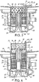
- Fig. 3 is a vertical section through the filter arrangement shown in Fig.2 with a coarse sieve in a first hidden position
- Fig. 4 is a the same section as Fig.3 but with the coarse sieve in a second visible position.
- Fig. 1 shows a dishwasher 10 that is provided with a wash space 11 in which dish is inserted on an upper and a lower basket 12, 13.In the wash space there is an upper (not shown) and a lower rotating spray arm 14 that directs the circulating liquid through spray nozzles towards the dish which is placed on the baskets 12,13.
- the circulating liquid falls down on the bottom 15 of the wash space 11 and is directed towards a filter arrangement 16 that covers a liquid collecting container 17 (see Fig. 3 and 4 ) from which the liquid by means of a circulation pump (not shown) is distributed to the spray arms.
- the filter arrangement 16 comprises a fine filter plate 18 that covers a rather large, mainly horizontal area and is arranged above the container 17.
- the container 17 supports a cup shaped, fine filter 19 comprising a tubular plastic frame 20 with large openings 21 covered by the fine filter material.
- the frame 20 is partly inserted into a tubular recess 22 at the lower end of the collecting container and has a bottom 23 provided with openings 24 covered by the same filter material.
- the upper end of the frame which is mainly flush with the upper surface of the fine filter plate 18, has a handle 25 resting against said surface whereas the bottom 23 is provided with a central opening 26 and a projecting lip 27 cooperating with a shoulder 28 in order to keep the frame 20 in place in the machine.
- the central opening 26 surrounds a piston 29 that extends upwards from a bottom 30 of the container and that cooperates with a cylinder 31.
- the cylinder/piston actuating arrangement 29,31 which is activated or deactivated by the program control, is a so called wax actuator in which a soft mass trapped in the cylinder is expanded when being heated.
- the wax actuator co-operates with a spring (not shown) that lifts the piston whereas the wax actuator pulls a wire to lower the piston.
- the upper part of the piston 29 is provided with a clamp means 32 on which a coarse sieve 33 is removably secured.
- the sieve 33 which preferably is made of plastic material comprises an upper cup shaped part 34 having a tubular wall 35 with an outer diameter slightly less than the inner diameter of the filter 19.
- the tubular wall 35 extends below an intermediate wall 36 that constitutes a bottom of the cup shaped part 34 and forms a skirt 37 .
- the tubular wall 35, the skirt 37 and the intermediate wall 36 are provided with comparatively large openings 38 forming the filtering areas of the sieve.
- the sieve is also provided with a handle 39 and the intermediate wall 36 has a central opening cooperating with the clamp means 32 to keep the sieve in removable engagement with the piston 29.
- the device operates in the following manner.
- dish is placed in the wash space 11 and cleaning liquid starts to circulate through the spray arms 14 the dirt is flushed from the dish and is distributed to the fine filter plate 18.
- a part of the liquid flows through the filter plate 18 into the container 17 whereas the main part of the soil together with the remaining part of the circulating liquid successively flows over the upper edge of the coarse strainer 33 which during the cleaning phase is in its lower position, see Fig. 3 .
- This means that larger particles and details are collected in the cup shaped part 34 whereas the liquid flows through the filter material in the openings 21 of the filter 19 into the bottom part of the container 17 from which the liquid is distributed to the spray arms by means of the circulation pump.
- the program control activates the cylinder/piston arrangement 29,31 which means that the piston rises the thereby bringing the coarse sieve 33 to the visible position shown in Fig 4 ..
- the skirt 37 still serves as a coarse sieve for the rinsing water flowing from the filter plate 18 into the interior of the filter 19 and further to the lower part of the container 17 whereas the cup shaped part 34 in this position is placed above the water flow. Consequently there will be no re-deposition of particles on the dish from the dirt that has been collected in the cup shaped part 34 during the rinsing stage.
- the coarse sieve 33 is kept in the upper position until the next dish starts.
- the coarse sieve is clearly visible and the coarse sieve can easily be disengaged from the clamp means 32 of the piston 29 by depressing the rod 40 at the handle 39.
- the sieve can then be emptied into a bin before it is again replaced on the clamp means.
- the fine filter 19 might be removed and cleaned as well as the filter plate 18.
Landscapes
- Washing And Drying Of Tableware (AREA)
Description
- This invention relates to a filter system for a household dishwasher comprising a wash space and a liquid circuit that comprises a coarse sieve and one or several fine filters the coarse sieve being movable between at least two positions with the aid of actuating means arranged in the dishwasher.
- Filter systems for conventional dishwashers usually comprise a coarse sieve in which larger details are collected and different types of fine filters or micro filters in which finer particles are trapped. The coarse sieve usually is a comparatively small cup shaped strainer hidden in a recess surrounded by a fine filter at the trough shaped bottom part of the wash chamber. This means that the collecting volume of the coarse sieve is small and that the circulating liquid flows through the dirt and soil trapped in the coarse sieve during the cleaning phase as well as under the rinsing phase. Thus, particles coming from the collected material in the coarse sieve might re-deposit and contaminate the dish during the rinsing phase. Because the small volume of the coarse sieve the sieve quickly gets filled if the dish is inserted into the wash chamber without being pre-washed. In order to avoid this people usually wash the dish under flushing water before putting it into the machine thereby increasing the water consumption and the energy consumption if hot water is used. Since the traditional coarse sieves are hidden at the bottom part of the wash chamber it is also usually hard for the operator to see the filling state of the coarse sieve.
- In order to drain out all soiled water before rinse water is taken in it is also previously known, see
US 5937879 , to use a coarse sieve that to some extent is lifted up during the rinse phase together with a plug that normally closes the drain opening. Since water flows through the coarse sieve in the lower as well as the upper position the risk for contaminating the dish in the rinsing phase is the same as has been described above. - The purpose of this invention is to create a new filter system making it possible to put the dish into the wash chamber without pre-washing it under flushing water and also to decrease the risk for contaminating the dish during the rinsing stage. A further purpose is to create a system that visualizes the filling state of the coarse sieve making it possible for the operator to easily see when the coarse sieve has to be emptied. This is achieved by means of a device having the characteristics mentioned in the claims.
- An embodiment of the invention will now be described with reference to the accompanying drawing on which
Fig. 1 is a perspective view of a dishwasher according to the invention,Fig. 2 is a perspective view of an uncovered part of the filter arrangement in the dishwasher,Fig. 3 is a vertical section through the filter arrangement shown inFig.2 with a coarse sieve in a first hidden position whereasFig. 4 is a the same section asFig.3 but with the coarse sieve in a second visible position. -
Fig. 1 shows adishwasher 10 that is provided with awash space 11 in which dish is inserted on an upper and alower basket 12, 13.In the wash space there is an upper (not shown) and a lower rotatingspray arm 14 that directs the circulating liquid through spray nozzles towards the dish which is placed on thebaskets bottom 15 of thewash space 11 and is directed towards afilter arrangement 16 that covers a liquid collecting container 17 (seeFig. 3 and 4 ) from which the liquid by means of a circulation pump (not shown) is distributed to the spray arms. - The
filter arrangement 16 comprises afine filter plate 18 that covers a rather large, mainly horizontal area and is arranged above thecontainer 17. Thecontainer 17 supports a cup shaped,fine filter 19 comprising a tubularplastic frame 20 withlarge openings 21 covered by the fine filter material. Theframe 20 is partly inserted into atubular recess 22 at the lower end of the collecting container and has abottom 23 provided withopenings 24 covered by the same filter material. The upper end of the frame, which is mainly flush with the upper surface of thefine filter plate 18, has ahandle 25 resting against said surface whereas thebottom 23 is provided with acentral opening 26 and a projectinglip 27 cooperating with ashoulder 28 in order to keep theframe 20 in place in the machine. - The
central opening 26 surrounds apiston 29 that extends upwards from abottom 30 of the container and that cooperates with acylinder 31. The cylinder/piston actuating arrangement - The upper part of the
piston 29 is provided with a clamp means 32 on which acoarse sieve 33 is removably secured. Thesieve 33 which preferably is made of plastic material comprises an upper cup shapedpart 34 having atubular wall 35 with an outer diameter slightly less than the inner diameter of thefilter 19. Thetubular wall 35 extends below anintermediate wall 36 that constitutes a bottom of the cup shapedpart 34 and forms askirt 37 . Thetubular wall 35, theskirt 37 and theintermediate wall 36 are provided with comparativelylarge openings 38 forming the filtering areas of the sieve. The sieve is also provided with ahandle 39 and theintermediate wall 36 has a central opening cooperating with the clamp means 32 to keep the sieve in removable engagement with thepiston 29. To lock thesieve 33 at the clamp means 32 there is a vertical elongated rod 40 whose upper end extends up above thehandle 39 and whose lower end co-operates with a spring loadedlocking bar 41. By depressing the rod 40 thesieve 33 is disengaged from thepiston 29 and when the sieve is again placed on the piston thelocking bar 41 again locks the sieve to the clamping means. - The device operates in the following manner. When dish is placed in the
wash space 11 and cleaning liquid starts to circulate through thespray arms 14 the dirt is flushed from the dish and is distributed to thefine filter plate 18. A part of the liquid flows through thefilter plate 18 into thecontainer 17 whereas the main part of the soil together with the remaining part of the circulating liquid successively flows over the upper edge of thecoarse strainer 33 which during the cleaning phase is in its lower position, seeFig. 3 . This means that larger particles and details are collected in the cup shapedpart 34 whereas the liquid flows through the filter material in theopenings 21 of thefilter 19 into the bottom part of thecontainer 17 from which the liquid is distributed to the spray arms by means of the circulation pump. - When the cleaning phase has been finished the program control activates the cylinder/
piston arrangement coarse sieve 33 to the visible position shown inFig 4 .. In this position theskirt 37 still serves as a coarse sieve for the rinsing water flowing from thefilter plate 18 into the interior of thefilter 19 and further to the lower part of thecontainer 17 whereas the cup shapedpart 34 in this position is placed above the water flow. Consequently there will be no re-deposition of particles on the dish from the dirt that has been collected in the cup shapedpart 34 during the rinsing stage. - The
coarse sieve 33 is kept in the upper position until the next dish starts. When the operator opens the door of the dishwasher the coarse sieve is clearly visible and the coarse sieve can easily be disengaged from the clamp means 32 of thepiston 29 by depressing the rod 40 at thehandle 39. The sieve can then be emptied into a bin before it is again replaced on the clamp means. At the same time thefine filter 19 might be removed and cleaned as well as thefilter plate 18. When a new dish starts the coarse sieve will be withdrawn and automatically return to its lower position. - It should be stressed that it of course is possible to use different kind arrangements instead of the wax actuator mentioned above to achieve the movement of the coarse sieve, for instance an electric motor, a spring, a solenoid or the water pressure from the circulation pump. It is also possible to connect the movement of the coarse sieve to the opening movement of the door in order to get the visible effect or to use other means in the dishwasher to cause the lifting movement when initiated by the operator in order to make it easier to remove the coarse sieve from the machine.
Claims (10)
- Filter system for a household dishwasher comprising a wash space (11) and a liquid circuit that comprises a coarse sieve (33) and one or several fine filters (18,19), the coarse sieve (33) being movable between at least two positions with the aid of actuating means (29,31) arranged in the dishwasher characterized in that a part of the circulating liquid in the first position (Fig.3) flows tluough a collecting part (34) of the coarse sieve (33) whereas the circulating liquid in the second position (Fig.4) flows outside said collecting part.
- Filter system according to claim 1 characterized in that the coarse sieve (33) is in the first position during the main part of the cleaning phase whereas the coarse sieve is in the second position during the main part of the rinsing phase.
- Filter system according to any of the previous claims characterized in that the collecting part (34) of the coarse sieve is cup shaped.
- Filter system according to any of the previous claims characterized in that coarse sieve (33) is provided with a filtering area (37) serving as a coarse sieve for the circulating liquid when the coarse sieve is in its second position.
- Filter system according to claim 4 characterized in that the collecting part (34) of the coarse sieve (33) is provided with a circular wall part and a bottom (36) whereas the filtering area (37) area constitutes an extension of the circular wall part below said bottom (36).
- Filter system according to any of the previous claims characterized in that said means (29,31) are activated and/or deactivated by the program control.
- Filter system according to any of the previous claims characterized in that the bottom of the wash space (10) is provided with a liquid collecting container (17) divided into a first and a second chamber by means of a the fine filter (19), the first chamber communicating with a circulation pump whereas the second chamber is arranged to receive the coarse sieve (33).
- Filter system according to claim 8 characterized in that the outer chamber is created by a tubular fine filter wall (21) and that the coarse sieve (33) has a corresponding shape and is movable axially from a lower position within the outer chamber to an upper position at least partly above the outer chamber.
- Filter system according to any of the preceding claims characterized in that said actuating means is placed below the coarse sieve.
- Filter system according to claim 9 characterized in that said actuating means (29,31) is a so called wax actuator.
Applications Claiming Priority (2)
| Application Number | Priority Date | Filing Date | Title |
|---|---|---|---|
| SE0301209A SE0301209D0 (en) | 2003-04-25 | 2003-04-25 | Filter system for a household dishwasher |
| PCT/SE2004/000527 WO2004096005A1 (en) | 2003-04-25 | 2004-04-02 | Filter system for a household dishwasher |
Publications (2)
| Publication Number | Publication Date |
|---|---|
| EP1619989A1 EP1619989A1 (en) | 2006-02-01 |
| EP1619989B1 true EP1619989B1 (en) | 2017-03-22 |
Family
ID=20291121
Family Applications (1)
| Application Number | Title | Priority Date | Filing Date |
|---|---|---|---|
| EP04725571.6A Expired - Lifetime EP1619989B1 (en) | 2003-04-25 | 2004-04-02 | Filter system for a household dishwasher |
Country Status (6)
| Country | Link |
|---|---|
| US (1) | US7980256B2 (en) |
| EP (1) | EP1619989B1 (en) |
| AU (1) | AU2004233725A1 (en) |
| PL (1) | PL1619989T3 (en) |
| SE (1) | SE0301209D0 (en) |
| WO (1) | WO2004096005A1 (en) |
Cited By (1)
| Publication number | Priority date | Publication date | Assignee | Title |
|---|---|---|---|---|
| CN112934818A (en) * | 2021-01-29 | 2021-06-11 | 龙南县方成科技有限公司 | Single-groove cleaning machine |
Families Citing this family (17)
| Publication number | Priority date | Publication date | Assignee | Title |
|---|---|---|---|---|
| US8252121B2 (en) | 2006-11-30 | 2012-08-28 | Premark Feg L.L.C. | Drain system for a warewasher |
| US20080237154A1 (en) * | 2007-02-06 | 2008-10-02 | Electrolux Home Products, Inc. | Filter device for a dishwasher, and associated apparatus and method |
| US8828148B2 (en) | 2007-02-06 | 2014-09-09 | Electrolux Home Products, Inc. | Dishwasher with accessible control unit, and associated method |
| US7942156B2 (en) * | 2008-11-20 | 2011-05-17 | Electrolux Home Products, Inc. | Screening arrangement for a dishwashing appliance, and associated apparatus |
| PL2233059T3 (en) * | 2009-03-27 | 2015-12-31 | Electrolux Home Products Corp Nv | Dishwasher |
| ES2422592T3 (en) | 2009-03-27 | 2013-09-12 | Electrolux Home Prod Corp | Dishwasher |
| PL2263512T5 (en) | 2009-06-17 | 2019-05-31 | Bonferraro Spa | Hood-type industrial dishwasher with improved filter assembly |
| PL2499954T3 (en) * | 2011-03-17 | 2017-10-31 | Electrolux Home Products Corp Nv | Dishwasher with a bistable filter |
| KR101970517B1 (en) * | 2012-06-04 | 2019-04-19 | 삼성전자주식회사 | Dish washer |
| CN103445740B (en) * | 2012-06-04 | 2018-03-06 | 三星电子株式会社 | Dish-washing machine |
| WO2016082889A1 (en) * | 2014-11-28 | 2016-06-02 | Arcelik Anonim Sirketi | Filter apparatus and dishwasher having the same |
| US9693670B2 (en) | 2015-01-15 | 2017-07-04 | Haier Us Appliance Solutions, Inc. | Filter assembly for a dishwasher appliance |
| CN106923772B (en) * | 2017-03-16 | 2019-03-19 | 湖南尔瞻智能科技有限公司 | The cleaning solution purification device of tableware specification cleaning device |
| CN106821262B (en) * | 2017-03-16 | 2019-04-26 | 湖南尔瞻智能科技有限公司 | Wash dishes liquid food residue filtering equipment |
| DE102019215312A1 (en) * | 2019-10-07 | 2021-04-08 | BSH Hausgeräte GmbH | Household dishwasher |
| CN113143144B (en) * | 2020-01-22 | 2022-11-01 | 宁波方太厨具有限公司 | Cleaning machine |
| DE102023210434A1 (en) * | 2023-10-23 | 2025-04-24 | BSH Hausgeräte GmbH | household dishwasher |
Family Cites Families (3)
| Publication number | Priority date | Publication date | Assignee | Title |
|---|---|---|---|---|
| IN186362B (en) * | 1995-07-01 | 2001-08-18 | Lg Electronics Inc | |
| US5660195A (en) * | 1996-03-05 | 1997-08-26 | White Consolidated Industries, Inc. | Dishwasher vent system |
| US5937880A (en) * | 1997-10-03 | 1999-08-17 | Tca, Inc. | Under counter dish washing machine |
-
2003
- 2003-04-25 SE SE0301209A patent/SE0301209D0/en unknown
-
2004
- 2004-04-02 EP EP04725571.6A patent/EP1619989B1/en not_active Expired - Lifetime
- 2004-04-02 WO PCT/SE2004/000527 patent/WO2004096005A1/en not_active Ceased
- 2004-04-02 AU AU2004233725A patent/AU2004233725A1/en not_active Abandoned
- 2004-04-02 PL PL04725571T patent/PL1619989T3/en unknown
- 2004-04-02 US US10/550,386 patent/US7980256B2/en not_active Expired - Fee Related
Non-Patent Citations (1)
| Title |
|---|
| None * |
Cited By (1)
| Publication number | Priority date | Publication date | Assignee | Title |
|---|---|---|---|---|
| CN112934818A (en) * | 2021-01-29 | 2021-06-11 | 龙南县方成科技有限公司 | Single-groove cleaning machine |
Also Published As
| Publication number | Publication date |
|---|---|
| US20070000525A1 (en) | 2007-01-04 |
| EP1619989A1 (en) | 2006-02-01 |
| WO2004096005A1 (en) | 2004-11-11 |
| PL1619989T3 (en) | 2017-09-29 |
| AU2004233725A1 (en) | 2004-11-11 |
| SE0301209D0 (en) | 2003-04-25 |
| US7980256B2 (en) | 2011-07-19 |
Similar Documents
| Publication | Publication Date | Title |
|---|---|---|
| US7980256B2 (en) | Filter system for a household dishwasher | |
| EP2283762B1 (en) | Water-transporting household device | |
| US11857133B2 (en) | Use of recycled wash and rinse water for the pre-rinse operation of dishes | |
| CN102245075B (en) | Pre-rinsing of dishes | |
| DE102011053666A1 (en) | DISHWASHER WITH FILTER CLEANING ASSEMBLY | |
| US10022034B2 (en) | Dishwasher appliance and method | |
| KR101645040B1 (en) | A dishwasher and a control method the same | |
| US5937879A (en) | Under counter dish washing machine | |
| CA2258396C (en) | Secondary filter system | |
| EP3435829B1 (en) | Granule valve arrangement for a dishwashing apparatus | |
| JP2024012642A (en) | Solid detergent dispenser for washing machines | |
| EP0288918B1 (en) | Dishwashing apparatus including a solid detergent dispenser | |
| KR20180106057A (en) | Dish washer | |
| CN106793914A (en) | With the draining for automating and the dish-washing machine for filling | |
| KR101322548B1 (en) | Dishwasher and Control Method | |
| JP3757346B2 (en) | Dishwasher | |
| EP1085833B1 (en) | Method and device in a cleaning machine | |
| KR20180106058A (en) | Control method for dish washer | |
| JP2001292944A (en) | Dishwasher | |
| KR100761171B1 (en) | Sump structure of dishwasher | |
| JPH06346494A (en) | Cleaning method with kitchen cleaning sink | |
| KR20250092006A (en) | Control method of dish washer | |
| WO1994025661A1 (en) | Washing machine having a filter removeable from above | |
| JPS63119730A (en) | Tableware washing machine | |
| AU663627B2 (en) | Filter screen assembly for dishwasher |
Legal Events
| Date | Code | Title | Description |
|---|---|---|---|
| PUAI | Public reference made under article 153(3) epc to a published international application that has entered the european phase |
Free format text: ORIGINAL CODE: 0009012 |
|
| 17P | Request for examination filed |
Effective date: 20051125 |
|
| AK | Designated contracting states |
Kind code of ref document: A1 Designated state(s): AT BE BG CH CY CZ DE DK EE ES FI FR GB GR HU IE IT LI LU MC NL PL PT RO SE SI SK TR |
|
| DAX | Request for extension of the european patent (deleted) | ||
| RAP1 | Party data changed (applicant data changed or rights of an application transferred) |
Owner name: ELECTROLUX HOME PRODUCTS CORPORATION N.V. |
|
| RAP1 | Party data changed (applicant data changed or rights of an application transferred) |
Owner name: ELECTROLUX HOME PRODUCTS CORPORATION N.V. |
|
| GRAP | Despatch of communication of intention to grant a patent |
Free format text: ORIGINAL CODE: EPIDOSNIGR1 |
|
| INTG | Intention to grant announced |
Effective date: 20161028 |
|
| RIN1 | Information on inventor provided before grant (corrected) |
Inventor name: HARTVIGSSON, MARCUS |
|
| GRAS | Grant fee paid |
Free format text: ORIGINAL CODE: EPIDOSNIGR3 |
|
| GRAA | (expected) grant |
Free format text: ORIGINAL CODE: 0009210 |
|
| AK | Designated contracting states |
Kind code of ref document: B1 Designated state(s): AT BE BG CH CY CZ DE DK EE ES FI FR GB GR HU IE IT LI LU MC NL PL PT RO SE SI SK TR |
|
| REG | Reference to a national code |
Ref country code: GB Ref legal event code: FG4D |
|
| REG | Reference to a national code |
Ref country code: CH Ref legal event code: EP |
|
| REG | Reference to a national code |
Ref country code: AT Ref legal event code: REF Ref document number: 876849 Country of ref document: AT Kind code of ref document: T Effective date: 20170415 |
|
| REG | Reference to a national code |
Ref country code: IE Ref legal event code: FG4D |
|
| REG | Reference to a national code |
Ref country code: DE Ref legal event code: R096 Ref document number: 602004050957 Country of ref document: DE |
|
| REG | Reference to a national code |
Ref country code: NL Ref legal event code: MP Effective date: 20170322 |
|
| PG25 | Lapsed in a contracting state [announced via postgrant information from national office to epo] |
Ref country code: GR Free format text: LAPSE BECAUSE OF FAILURE TO SUBMIT A TRANSLATION OF THE DESCRIPTION OR TO PAY THE FEE WITHIN THE PRESCRIBED TIME-LIMIT Effective date: 20170623 Ref country code: FI Free format text: LAPSE BECAUSE OF FAILURE TO SUBMIT A TRANSLATION OF THE DESCRIPTION OR TO PAY THE FEE WITHIN THE PRESCRIBED TIME-LIMIT Effective date: 20170322 |
|
| REG | Reference to a national code |
Ref country code: AT Ref legal event code: MK05 Ref document number: 876849 Country of ref document: AT Kind code of ref document: T Effective date: 20170322 |
|
| PG25 | Lapsed in a contracting state [announced via postgrant information from national office to epo] |
Ref country code: BG Free format text: LAPSE BECAUSE OF FAILURE TO SUBMIT A TRANSLATION OF THE DESCRIPTION OR TO PAY THE FEE WITHIN THE PRESCRIBED TIME-LIMIT Effective date: 20170622 Ref country code: SE Free format text: LAPSE BECAUSE OF FAILURE TO SUBMIT A TRANSLATION OF THE DESCRIPTION OR TO PAY THE FEE WITHIN THE PRESCRIBED TIME-LIMIT Effective date: 20170322 |
|
| PG25 | Lapsed in a contracting state [announced via postgrant information from national office to epo] |
Ref country code: NL Free format text: LAPSE BECAUSE OF FAILURE TO SUBMIT A TRANSLATION OF THE DESCRIPTION OR TO PAY THE FEE WITHIN THE PRESCRIBED TIME-LIMIT Effective date: 20170322 |
|
| PG25 | Lapsed in a contracting state [announced via postgrant information from national office to epo] |
Ref country code: CZ Free format text: LAPSE BECAUSE OF FAILURE TO SUBMIT A TRANSLATION OF THE DESCRIPTION OR TO PAY THE FEE WITHIN THE PRESCRIBED TIME-LIMIT Effective date: 20170322 Ref country code: AT Free format text: LAPSE BECAUSE OF FAILURE TO SUBMIT A TRANSLATION OF THE DESCRIPTION OR TO PAY THE FEE WITHIN THE PRESCRIBED TIME-LIMIT Effective date: 20170322 Ref country code: SK Free format text: LAPSE BECAUSE OF FAILURE TO SUBMIT A TRANSLATION OF THE DESCRIPTION OR TO PAY THE FEE WITHIN THE PRESCRIBED TIME-LIMIT Effective date: 20170322 Ref country code: ES Free format text: LAPSE BECAUSE OF FAILURE TO SUBMIT A TRANSLATION OF THE DESCRIPTION OR TO PAY THE FEE WITHIN THE PRESCRIBED TIME-LIMIT Effective date: 20170322 Ref country code: RO Free format text: LAPSE BECAUSE OF FAILURE TO SUBMIT A TRANSLATION OF THE DESCRIPTION OR TO PAY THE FEE WITHIN THE PRESCRIBED TIME-LIMIT Effective date: 20170322 Ref country code: EE Free format text: LAPSE BECAUSE OF FAILURE TO SUBMIT A TRANSLATION OF THE DESCRIPTION OR TO PAY THE FEE WITHIN THE PRESCRIBED TIME-LIMIT Effective date: 20170322 |
|
| PG25 | Lapsed in a contracting state [announced via postgrant information from national office to epo] |
Ref country code: PT Free format text: LAPSE BECAUSE OF FAILURE TO SUBMIT A TRANSLATION OF THE DESCRIPTION OR TO PAY THE FEE WITHIN THE PRESCRIBED TIME-LIMIT Effective date: 20170724 |
|
| REG | Reference to a national code |
Ref country code: CH Ref legal event code: PL |
|
| REG | Reference to a national code |
Ref country code: DE Ref legal event code: R097 Ref document number: 602004050957 Country of ref document: DE |
|
| REG | Reference to a national code |
Ref country code: IE Ref legal event code: MM4A |
|
| PLBE | No opposition filed within time limit |
Free format text: ORIGINAL CODE: 0009261 |
|
| REG | Reference to a national code |
Ref country code: FR Ref legal event code: ST Effective date: 20171229 |
|
| STAA | Information on the status of an ep patent application or granted ep patent |
Free format text: STATUS: NO OPPOSITION FILED WITHIN TIME LIMIT |
|
| PG25 | Lapsed in a contracting state [announced via postgrant information from national office to epo] |
Ref country code: MC Free format text: LAPSE BECAUSE OF FAILURE TO SUBMIT A TRANSLATION OF THE DESCRIPTION OR TO PAY THE FEE WITHIN THE PRESCRIBED TIME-LIMIT Effective date: 20170322 Ref country code: FR Free format text: LAPSE BECAUSE OF NON-PAYMENT OF DUE FEES Effective date: 20170522 Ref country code: DK Free format text: LAPSE BECAUSE OF FAILURE TO SUBMIT A TRANSLATION OF THE DESCRIPTION OR TO PAY THE FEE WITHIN THE PRESCRIBED TIME-LIMIT Effective date: 20170322 |
|
| 26N | No opposition filed |
Effective date: 20180102 |
|
| GBPC | Gb: european patent ceased through non-payment of renewal fee |
Effective date: 20170622 |
|
| PG25 | Lapsed in a contracting state [announced via postgrant information from national office to epo] |
Ref country code: LI Free format text: LAPSE BECAUSE OF NON-PAYMENT OF DUE FEES Effective date: 20170430 Ref country code: LU Free format text: LAPSE BECAUSE OF NON-PAYMENT OF DUE FEES Effective date: 20170402 Ref country code: CH Free format text: LAPSE BECAUSE OF NON-PAYMENT OF DUE FEES Effective date: 20170430 Ref country code: SI Free format text: LAPSE BECAUSE OF FAILURE TO SUBMIT A TRANSLATION OF THE DESCRIPTION OR TO PAY THE FEE WITHIN THE PRESCRIBED TIME-LIMIT Effective date: 20170322 |
|
| REG | Reference to a national code |
Ref country code: BE Ref legal event code: MM Effective date: 20170430 |
|
| PG25 | Lapsed in a contracting state [announced via postgrant information from national office to epo] |
Ref country code: IE Free format text: LAPSE BECAUSE OF NON-PAYMENT OF DUE FEES Effective date: 20170402 Ref country code: GB Free format text: LAPSE BECAUSE OF NON-PAYMENT OF DUE FEES Effective date: 20170622 |
|
| PG25 | Lapsed in a contracting state [announced via postgrant information from national office to epo] |
Ref country code: BE Free format text: LAPSE BECAUSE OF NON-PAYMENT OF DUE FEES Effective date: 20170430 |
|
| PGFP | Annual fee paid to national office [announced via postgrant information from national office to epo] |
Ref country code: PL Payment date: 20180328 Year of fee payment: 15 |
|
| PGFP | Annual fee paid to national office [announced via postgrant information from national office to epo] |
Ref country code: DE Payment date: 20180420 Year of fee payment: 15 |
|
| PGFP | Annual fee paid to national office [announced via postgrant information from national office to epo] |
Ref country code: IT Payment date: 20180423 Year of fee payment: 15 Ref country code: TR Payment date: 20180402 Year of fee payment: 15 |
|
| PG25 | Lapsed in a contracting state [announced via postgrant information from national office to epo] |
Ref country code: HU Free format text: LAPSE BECAUSE OF FAILURE TO SUBMIT A TRANSLATION OF THE DESCRIPTION OR TO PAY THE FEE WITHIN THE PRESCRIBED TIME-LIMIT; INVALID AB INITIO Effective date: 20040402 |
|
| PG25 | Lapsed in a contracting state [announced via postgrant information from national office to epo] |
Ref country code: CY Free format text: LAPSE BECAUSE OF NON-PAYMENT OF DUE FEES Effective date: 20170322 |
|
| REG | Reference to a national code |
Ref country code: DE Ref legal event code: R119 Ref document number: 602004050957 Country of ref document: DE |
|
| PG25 | Lapsed in a contracting state [announced via postgrant information from national office to epo] |
Ref country code: DE Free format text: LAPSE BECAUSE OF NON-PAYMENT OF DUE FEES Effective date: 20191101 |
|
| PG25 | Lapsed in a contracting state [announced via postgrant information from national office to epo] |
Ref country code: IT Free format text: LAPSE BECAUSE OF NON-PAYMENT OF DUE FEES Effective date: 20190402 |
|
| PG25 | Lapsed in a contracting state [announced via postgrant information from national office to epo] |
Ref country code: PL Free format text: LAPSE BECAUSE OF NON-PAYMENT OF DUE FEES Effective date: 20190402 |
|
| PG25 | Lapsed in a contracting state [announced via postgrant information from national office to epo] |
Ref country code: TR Free format text: LAPSE BECAUSE OF NON-PAYMENT OF DUE FEES Effective date: 20190402 |