EP1619769A1 - Dc power supply system and switch - Google Patents
Dc power supply system and switch Download PDFInfo
- Publication number
- EP1619769A1 EP1619769A1 EP04719059A EP04719059A EP1619769A1 EP 1619769 A1 EP1619769 A1 EP 1619769A1 EP 04719059 A EP04719059 A EP 04719059A EP 04719059 A EP04719059 A EP 04719059A EP 1619769 A1 EP1619769 A1 EP 1619769A1
- Authority
- EP
- European Patent Office
- Prior art keywords
- power
- battery
- short
- storage device
- switch
- Prior art date
- Legal status (The legal status is an assumption and is not a legal conclusion. Google has not performed a legal analysis and makes no representation as to the accuracy of the status listed.)
- Withdrawn
Links
Images


Classifications
-
- H—ELECTRICITY
- H02—GENERATION; CONVERSION OR DISTRIBUTION OF ELECTRIC POWER
- H02J—CIRCUIT ARRANGEMENTS OR SYSTEMS FOR SUPPLYING OR DISTRIBUTING ELECTRIC POWER; SYSTEMS FOR STORING ELECTRIC ENERGY
- H02J9/00—Circuit arrangements for emergency or stand-by power supply, e.g. for emergency lighting
- H02J9/04—Circuit arrangements for emergency or stand-by power supply, e.g. for emergency lighting in which the distribution system is disconnected from the normal source and connected to a standby source
- H02J9/06—Circuit arrangements for emergency or stand-by power supply, e.g. for emergency lighting in which the distribution system is disconnected from the normal source and connected to a standby source with automatic change-over, e.g. UPS systems
-
- H—ELECTRICITY
- H02—GENERATION; CONVERSION OR DISTRIBUTION OF ELECTRIC POWER
- H02J—CIRCUIT ARRANGEMENTS OR SYSTEMS FOR SUPPLYING OR DISTRIBUTING ELECTRIC POWER; SYSTEMS FOR STORING ELECTRIC ENERGY
- H02J7/00—Circuit arrangements for charging or depolarising batteries or for supplying loads from batteries
- H02J7/34—Parallel operation in networks using both storage and other dc sources, e.g. providing buffering
- H02J7/345—Parallel operation in networks using both storage and other dc sources, e.g. providing buffering using capacitors as storage or buffering devices
Definitions
- the present invention relates to a DC power system and a switch mainly used for a control system at an electric power plant or a substation, or for a control system at substation facilities of a building, an electric railway or the like.
- the substation has a role of not only converting power into voltages suited to power transmission or use to distribute them to a plurality of demand places or households, but also instantaneously cutting off an accident power transmission system at the time of an accident to minimize influences on other systems.
- the substation comprises a control system constituted of a switch such as a breaker, a disconnector or an earth device.
- a power station and substation As those that comprise the same control system as that of the substation, there are feeding substation facilities and the like of an electric power plant, a switch, a power supply station, a building, an electric railway and the like.
- these will be collectively called a power station and substation, and a conventional example will be described.
- FIG. 14 is a circuitry diagram showing power supply facilities at a conventional power station and substation.
- high voltage power from a bus line 2 of a power supply system 1 is supplied through power lines 3a, 3b to distribution boards 11a, 11b.
- the power set to low voltages by the distribution boards 11a, 11b is provided to a power board 15 via a DC power system 14, and the power is supplied to each DC device (not shown) from this power board 15.
- the DC power system 14 is connected to two systems, i.e., the distribution boards 11a, 11b, through the bus line 2. It is for the purpose of supplying power by the other system when one of the two systems cuts off power supply.
- the DC power system 14 comprises a rectifier circuit 16, and a DC storage device 17 such as a lead battery.
- the rectifier 16 converts AC power set to a low voltage into DC power to supply it to the power board 15 and to charge the DC storage device 14. For example, when power supply is cut off at a system of a primary side (bus line side), power is supplied from the DC storage device 17 to each DC device via the power board 15.
- AC power is directly supplied from the distribution boards 11a, 11b through cables 10a, 10b to AC loads in the station.
- DC devices to be operated by the DC storage device 17 are a driving mechanism (DC motor, or pull-out or input coil) of a switch installed in a switch installation area, a relay, a state indication light, a control unit, and the like.
- FIG. 15 is a DC power circuitry diagram of a switch control system at the power station and substation.
- a DC power source of the power board 15 is connected to driving mechanisms or relays of switches 18a, 18b, 18c via a protection control device 19 such as a control board, a protection relay board or a recorder installed in a power station and substation control monitor room 50, a relay and a control unit in a site control board 82 installed in the switch installation area 32, and the site control board 82.
- a protection control device 19 such as a control board, a protection relay board or a recorder installed in a power station and substation control monitor room 50, a relay and a control unit in a site control board 82 installed in the switch installation area 32, and the site control board 82.
- the switches 18a, 18b 18c include a breaker, a disconnector, an earth device and the like, and a combination thereof.
- a control current is about 5 amperes (A) a phase, and time necessary for a switching operation is an order of 100 ms.
- the DC storage device 17 needs a capacity to simultaneously control all the gas breakers.
- the disconnector and the earth device are controlled in accordance with a sequence.
- a control current of several A must be output for about 10 seconds.
- L is a maintenance factor
- C is a capacity conversion time coefficient
- I is a necessary current.
- the capacity conversion time coefficient varies from one lead battery mode to another. Maintenance time is as shown in a graph of FIG. 16.
- the above configuration necessitates an output of a large current of several 100 A from the storage device to an operation mechanism of the switch or the like. Accordingly, a thick and heavy large-capacity cable is used.
- a large-capacity electric double-layer capacitor (referred to as EDLC battery hereinafter) capable of supplying a large current for a short time
- a secondary battery that has characteristics of both a secondary battery such as a lead battery, and an electrolytic capacitor (e.g., Jpn. Pat. Appln. KOKAI Publication No. 2002-34179) has been developed, and commercialized.
- this EDLC battery can output large power, and is suitable as a power source for a device which needs a large current within a short time.
- the EDLC battery has excellent characteristics of the secondary battery such as a low environmental load, high-speed chargeability, and a compact form.
- the EDLC battery needs several 100 cells to connect an output of several 10 minutes, causing increases in size and costs of the device. Additionally, the number of balance circuits installed to prevent an excess voltage applied on the EDLC is increased corresponding to the number of cells, causing increases in costs and failure risks. Thus, advantages of using the EDLC battery are lost.
- a first aspect of the present invention is directed to a DC power system comprising a rectifier which converts AC power supplied from an AC power source in a power station and substation into DC power to supply the DC power to a DC load; and a storage device normally charged by the DC power output from the rectifier, characterized in that the storage device is divided into a DC short-time storage device which maintains power supply only for a predetermined short time when power supply from the power source in the power station and substation is cut off, and a DC long-time storage device which maintains power supply for a time relatively longer than that of the DC short-time storage device; the DC short-time storage device is equipped with a first battery; the DC long-time storage device is equipped with a second battery; the first battery has an output density larger than that of the second battery; and the second battery has an energy density larger than that of the first battery.
- a second aspect of the present invention is directed to a switch installed in a switch installation area of a substation, substation facilities or the like, characterized in that a DC short-time storage device equipped with a battery having a predetermined high output density as a DC power source to drive or control an operation device which cuts off or puts in a switch main body is disposed in a housing box selected from an operation box of the switch, a site control board, and a housing box only for the DC short-time storage device.
- the present invention it is possible to achieve low costs of the storage device in the electric station such as a power station and substation, to reduce space of the storage device, and to reduce weight.
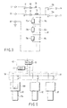
- FIG. 1 is a circuitry diagram showing a first embodiment in which a DC power system of the present invention is applied to a power supply system in a power station and substation.
- high voltage power from a bus line 2 from a power supply system 20 is supplied through power lines 3a, 3b to distribution boards 21a, 21b.
- Outputs of AC power reduced to low voltages at the distribution boards 21a, 21b are divided into two systems. One thereof is supplied to a DC short-time power supply system 23 which comprises a DC short-time power supply source 24 and a DC short-time power supply board 25, and the other is supplied to a DC long-time power supply system 33 which comprises a DC long-time power supply source 34 and a DC long-time power supply board 35.
- the DC short-time power supply source 24 comprises a rectifier 26 for converting AC power of the distribution boards 21a, 21b into DC power, and a DC short-time storage device 27 constituted of a large-capacity electric double-layer capacitor (referred to as "electric double-layer capacitor (EDLC) battery” hereinafter) 41 having a predetermined high output density, a charging device 42, and a DC-DC converter 43 as shown in FIG. 2.
- a rectifier 26 for converting AC power of the distribution boards 21a, 21b into DC power
- a DC short-time storage device 27 constituted of a large-capacity electric double-layer capacitor (referred to as "electric double-layer capacitor (EDLC) battery” hereinafter) 41 having a predetermined high output density, a charging device 42, and a DC-DC converter 43 as shown in FIG. 2.
- EDLC electric double-layer capacitor
- the EDLC battery 41 has recently been developed as a new battery which has characteristics of both a secondary battery such as a lead battery and an electrolytic capacitor. Different from a conventional secondary battery such as a lead battery, a current can be large, and thus it is suited to a device which needs a large current within a short time. In addition, the EDLC battery has excellent characteristics of the secondary battery such as a low environmental load, high-speed chargeability, and a compact form.
- the DC long-time power supply source 34 comprises a rectifier 36 for converting AC power of the distribution boards 21a, 21b into DC power, and a DC long-time storage device 37 constituted of, e.g., a lead battery having a predetermined energy density (storage power density).
- a NAS battery As the DC long-time storage device 37, in place of the lead battery, a NAS battery, an alkaline battery, or a nicad battery may be used.
- the EDLC battery has a smaller energy density while its output density is lager than that of the battery used for the DC long-time storage device.
- DC short-time power supply system 23 at the DC short-time power supply source 24, AC power reduced to a low voltage is converted into DC power by the rectifier 26, and output to the DC short-time power supply board 25.
- the DC power supplied from the rectifier 26 is supplied to the EDLC battery 41 via the charging circuit 42 of the DC short-time storage device 27 shown in FIG. 2, thereby charging the EDLC battery 41 to be always a fixed voltage or more.
- DC power reduced to a low voltage is converted into DC power by the rectifier 36, and output to the DC long-time power supply board 35.
- the DC power output from the rectifier 36 charges the lead battery of the DC long-time storage device 34 to be always a fixed voltage or more.
- DC power is supplied from the lead battery of the DC long-time storage device 37 to the DC long-time power supply board 35 for several minutes.
- FIG. 3 a configuration example of the EDLC battery 41 added to the DC short-time power supply source 24 will be described.
- the EDLC battery 41 is configured by serially connecting a plurality of EDLC cells 69a, 69b, 69c, ... (e.g., 50 EDLC cells of a capacity 200 F).
- Balancer circuits 70a, 70b, 70c, ... to balance voltages are connected in parallel to the EDLC cells 69a, 69b, 69c, ...
- An EDLC battery 64 comprises two charging terminals 71, 72 for main charging and high-speed charging on an input side, and two output terminals 73, 74 for control on an output side.
- One end of a serial circuit constituted of a limit resistor (e.g., 50 ⁇ ) 75, a reverse flow prevention diode 76 and a cut-off switch 77 is connected to the main charging terminal 71, and the other end of the serial circuit is connected through cut-off switches 78a, 78b to the output terminals 73, 74.
- One end of a serial circuit constituted of a limit resistor (e.g., 10 ⁇ ) 79, a reverse flow prevention diode 80, and a cut-off switch 81 is connected to another high-speed charging terminal 72.
- the other end of the serial circuit is connected in common with the other end of the serial circuit of the main charging terminal 71 side, and one end of the serial circuit of the EDLC cells 69a, 69b, 69c, ... is connected to this common contact.
- the other end of the serial circuit of the EDLC cells 69a, 69b, 69c, ... is connected to an earth terminal 82.
- a separately installed high-speed charging DC power source (not shown) is connected to the high-speed charging terminal 72.
- all the cut-off switches are in unconnected states. In this state, the cut-off switch 81 is turned ON, and the separately installed high-speed charging DC power source is turned ON, whereby the EDLC cell is charged at a high speed.
- the high-speed charging cut-off switch 81 is turned OFF, and the separately installed high-speed charging DC power source is removed. Then, when a main charging cut-off switch 77 and an output cut-off switch 78a are turned ON, electric charging is carried out by the DC output device 63 thereafter.
- the DC power system is divided into the two systems, i.e., the DC short-time power supply source 24 and the DC long-time power supply source 34, and the DC short-time power supply source 24 comprises the DC short-time storage device 27 equipped with the EDLC battery 41.
- the conventional secondary battery such as a lead battery
- large power can be output for a predetermined short time.
- the EDLC battery 41 is used different from the case of the conventional secondary battery. Thus, an environmental load can be reduced, and high-speed charging can be achieved.
- the DC-DC converter 43 is used for the DC short-time storage device 27 to compensate for a reduction in output voltage during discharging.
- the DC-DC converter can be omitted.
- the AC outputs of the distributors 21a, 21b are supplied through the two systems to the rectifiers 26, 36, and the DC power obtained by converting the AC outputs at the rectifiers is supplied to the DC short-time storage device 27 and the DC long-time storage device 37.
- operation effects similar to those of the embodiment can be obtained by employing a configuration in which the AC outputs of the distributors 21a, 21b are supplied to one rectifier, an output system of the rectifier is divided into two, and one thereof is used to supply DC power to the DC short-time storage device 27 and the other is used to supply DC power to the DC long-time storage device 37.
- a wiring method in addition to the above may be used.
- the system is divided into a system which needs a large current and a system which needs a long-time output, and the EDLC battery is applied to the system which needs the large current, whereby operation effects similar to those of the embodiment can be obtained.
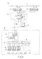
- FIG. 4 is a circuitry diagram showing a case in which a second embodiment of a DC power system of the present invention is applied to a control system in a power station and substation.
- high voltage power from a bus line 2 from a power supply system 20 is supplied through power lines 3a, 3b to distribution boards 21a, 21b.
- Outputs of AC power reduced to low voltages at the distribution boards 21a, 21b are divided into two systems. One thereof is supplied through a commonly connected wiring 51 to a DC long-time power supply source 52 installed in a power station and substation control monitor room 50, and the other is supplied through a commonly connected wiring 61 to a short-time power supply source 62 installed in a dedicated box of a switch installation area 60.
- the DC long-time power supply source 52 comprises a DC output device constituted of a rectifier circuit, and a DC long-time storage device 54 constituted of a lead battery or the like.
- This long-time power supply source 52 is connected to a DC long-time power supply board 55.
- a partial wiring 56a pulled out of the DC long-time power supply board 55 is connected to a protection control device 57 such as a control board, a protection relay board, or a recorder installed in the power station and substation control monitor room 50, and power is supplied to each.
- Another wiring 56b is connected to a small current control circuit 86 such as a display circuit or an interlocking circuit of a switch via a site control board 84 installed in the switch installation area 60, and power is supplied to each.
- the DC long-time power supply source 52, the DC long-time supply board 55, and the wirings 56a, 56b constitute a DC long-time power supply system.
- the DC short-time power supply source 62 comprises a DC output device 63 and an EDLC battery 64 which are constituted of rectifier circuits.
- An output of the DC short-time power supply source 62 is connected through the site control board 84 to large current short-time control circuits 85 such as pull-out coil, input coil control circuits or driving DC motor control circuits of breakers 66-1a, 66-1b, 66-1c, 66-2a, 66-2b, 66-2c, ... corresponding to a plurality of three phases.
- FIG. 5 is a circuit diagram showing a pull-out circuit of an operation device in detail in each breaker 66 to which DC power is supplied from the DC short-time power source 62 through the DC power line 65.
- 66a is a breaker main body connected to a main circuit (not shown)
- 66b is an operation box of a breaker equipped with a pull-out coil L connected to the DC power source 65
- 84 is a site control board serially installed in the pull-out coil L and equipped with a contact S closed based on a pull-out command from a control deice of a control room in the station.
- the pull-out circuit alone of the operation device has been described. However, the input circuit is similarly configured.
- the case of supplying the DC power from the DC short-time power supply source 62 to the pull-out circuit 66b of the operation circuit of the breaker 66 has been described.
- the operation device such as a disconnector or an earth device, a device which needs short-time power supply is connected to the DC power line 65 as in the above case.
- the DC short-time power supply source 62 of the switch installation area 60 at the DC output device 63, AC power reduced to a low voltage is converted into DC power by the rectifier circuit, and output to the DC power line 65.
- the EDLC battery 64 is charged to be always a fixed voltage or more. In this case, as a charge current is, e.g., 1A or less per EDLC battery 64, wiring is possible from the DC output device 63 to the EDLC battery 64 by a thin cable.
- DC long-time power supply source 52 of the substation control room 50 at the DC output device 53, AC power reduced to a low voltage is converted into DC power by the rectifier circuit, and output to the DC long-time power supply board 55.
- DC power is supplied from the DC long-time power supply board 55 to the control device 57 or the like, and simultaneously the DC long-time storage device 54 is charged.
- the DC short-time power supply source 62 constituted of the EDLC battery in the switch installation area 60, even when power supply is cut off in the station, power supply can be secured to operate the switch of the substation.
- the conventional secondary battery such as a lead battery
- large power can be output for a short time.
- costs, a size, and weight can be greatly reduced.
- the power supply source for the short time has conventionally been integrated with that for the long time, consequently necessitating a wide site, and it has been arranged in the substation control room (or power source room).
- the substation control room or power source room.
- a large current of 100 to 400 A must be supplied to the switch when power supply is cut off, a thick cable having a corresponding capacity must be laid from the control room to the switch installation area.
- a wiring space is necessary, and time and costs are necessary for wiring when a substation is constructed or reconstructed.
- the cable laid from the distribution board to the DC short-time power supply source is necessary for charging the EDLC battery, and a necessary capacity is only about 10 A.
- a necessary capacity is only about 10 A.
- the cable to supply a large current is only from the EDLC battery to the operation device of each switch. Thus, construction costs, an area necessary for wiring, and the like can be greatly reduced.
- a length of the cable from the battery to a load may become several 10 m, increasing electric resistance, and a necessary cable may become thick.
- a load e.g., breaker
- the cable length can be shortened, eliminating the necessity of considering a potential drop.
- FIG. 6 is a circuitry diagram showing a case in which a third embodiment of a DC power system of the present invention is applied to a control system in a power station and substation. Portions similar to those of FIG. 4 are denoted by similar reference numerals, and description thereof will be omitted. Different portions will be described.
- the DC short-time power supply source 62 that comprises the DC output device 63 constituted of the rectifier, and the EDLC battery 64 is arranged in the switch installation area.
- a DC output device 63 is arranged in a control monitor room 50, power converted into DC power is supplied through a cable to a DC power line 65 arranged in a switch installation area, and a plurality of EDLC batteries 64a, 64b, ... connected to the DC power line 65 corresponding to each of switches grouped into a plurality, e.g., breakers 66-1a to 66-1c, 66-2a to 66-2c, 66-3a to 66-3c, 66-4a to 66-4c, ..., are charged.
- the embodiment shows an example in which the EDLC batteries 64a, 64b are housed in site control boards 87a, 87b.
- the switches of the switch installation area are grouped into the plurality, and the EDLC batteries 64a, 64b, ... are arranged corresponding to the groups. Accordingly, the number and a capacity of EDLC batteries 64a, 64b, ..., and how to set writing to the control device can be optimized according to a configuration of the substation. Moreover, as the DC output device 63 installed in the control monitor room is used in common by the EDLC batteries 64a, 64b, ... arranged corresponding to the switch groups, the number of DC output devices 63 can be reduced to simplify the entire device.
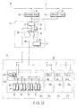
- FIG. 7 is a circuitry diagram showing a case in which a fourth embodiment of a DC power system of the present invention is applied to a control system in a power station and substation. Portions similar to those of FIG. 3 are denoted by similar reference numerals, and description thereof will be omitted. Different portions will be described.
- an output end of a DC output device 53 of a DC long-time power supply source 52 installed in a control monitor room and a DC power line 65 in a switch installation area are connected to each other through a cable 88, and a plurality of EDLC batteries 64a, 64b, ... connected to the DC power line 65 corresponding to each of switches grouped into a plurality, e.g., breakers 66-1a to 66-1c, 66-2a to 66-2c, 66-3a to 66-3c, 66-4a to 66-4c, ..., are charged.
- the second to fourth embodiments have been described by way of case in which the DC short-time power supply system 62 or the EDLC battery 64 are installed in the switch installation area separately from the switch.
- the DC output device (rectifier) 63 or the EDLC battery 64 of the DC short-time power supply source 62 for controlling the driving of the operation device of the switch may be disposed in the operation box which houses the operation device of the switch.
- FIG. 8 shows a configuration in which the DC output device 63 is installed, e.g., outside the breaker, and the EDLC battery 64 for controlling the driving of the operation device 66b of each of the breakers 66-1a, 66-1b, and 66-1c corresponding to the three phases is housed in the operation box.
- FIG. 9 shows a configuration in which for example, the DC output device 66b constituted of the rectifier and the EDLC battery 64 are housed in the operation box for controlling the driving of the operation device 66b of each of the breakers 66-1a to 66-1c corresponding to the three phases.
- FIG. 10 shows a configuration in which for example, the DC output device 63 and the EDLC battery 64 are housed in the operation box of one of the breakers 66-1a to 66-1c corresponding to the three phases, and a connection is made to enable supplying of DC power from the DC short-time power source to control driving of the operation device 66b of the other breaker.
- FIG. 11 shows a configuration in which the DC output device 63 and the EDLC battery 64 are housed in the operation box of one of the breakers 66-1a to 66-1c corresponding to the three phases, the EDLC battery 64 alone is housed in the other operation box, and a connection is made to enable charging of the EDLC battery 64 in the other operation box by a DC current output from the DC output device 63 in one operation box.
- the DC output device (rectifier) 63 and the EDLC battery 64 are housed in the operation box of the switch.
- an installing and housing mode thereof is not limited to this.
- a configuration of housing in a site operation board in place of the operation box of the switch, or a configuration of disposing a dedicated housing box of the DC short-time storage device and housing it therein can be employed. In these cases, effects similar to those of the above can be obtained.
- so-called external mounting may be employed in which a mounting mechanism mountable to one of a tank or the operation box of the switch and the site operation board is disposed in the DC short-time storage device and, by this mounting mechanism, the DC output device (rectifier) 63 or the EDLC battery 64 is mounted to an outer periphery of the tank or the operation box of the switch, or the site operation board.
- the embodiment has been descried by way of example in which the breaker is used as the switch, and driving or control of the operation device is carried out by the DC short-time power source.
- the embodiment can be applied to a disconnector or an earth device as a switch.
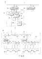
- FIG. 12 is a circuitry diagram showing a case in which a fifth embodiment of a DC power system of the present invention is applied to a control system in a power station and substation. Portions similar to those of FIG. 3 are denoted by similar reference numerals, and description thereof will be omitted. Different potions will be described.
- the embodiment employs a configuration in which an output end of a DC output device 53 of a DC long-time power supply source 52 installed in a control monitor room and a DC power line 65 in a switch installation area 60 are connected to each other through a cable 88, and EDLC batteries 64a, 64b, 64c, ... incorporated in housing boxes 87a, 87b, 87c, ... of a plurality of switches 81a, 81b, 81c, ... are connected to the DC power line 65.
- FIG. 13 is a circuit diagram showing an internal configuration example of the switch 81.
- This switch 81 comprises a breaker 82 connected to a main circuit of a power system, disconnectors 83, 84 sandwiching the breaker 82 to be connected to both sides thereof, and an earth device 85 connected between a power path for interconnecting the breaker 82 and the disconnector 83 and an earth point.
- a DC current is supplied from an EDLC battery 64 installed in a housing box such as an operation box of the switch 81, a site control board, or a dedicated box to an operation device of the breaker 82, the disconnectors 83, 84, and the earth device 85 to perform a predetermined sequential operation.
- a pull-out circuit of the breaker 82 is excited by a DC current supplied from the EDLC battery 64, and the breaker 82 performs a cut-off operation to cut off the power system. Then, after the breaker 82 is completely set in an electric cut-off state by the DC current supplied from the EDLC battery 64, a control operation is set to simultaneously open the disconnectors 83, and 84, and close the earth device 85.
- the EDLC battery 64 is installed in the housing box of the switch 81 to contribute as the driving power source for each switch, effects similar to those of the second embodiment can be obtained, and not only a structure can be simplified because the external wiring of a large-current cable is made unnecessary different from the case in which the EDLC battery 64 is disposed outside the switch 81, but also an accident that accompanies cable wiring can be prevented, and site assembling costs can be reduced.
- the common from is made with the DC output device 53 of the DC long-time power supply source 52 installed as the DC output device in the control monitor room, and its DC output is supplied through the cable 88 and the DC power line 65 to the EDLC batteries 64a, 64b, 64c, ... incorporated in the housing boxes 89a, 89b, 89c, ... of the switches 81a, 81b, 81c, ... to charge the same.
- the DC output device may be integrated with the EDLC battery to be incorporated in the housing box 89 of each switch 81.
- one EDLC battery is incorporated in the housing box of one switch, and a DC current is supplied to the operation device of each switch.
- the EDLC may be incorporated in a form shown in one of FIGS. 8 to 11.
- the EDLC battery incorporated in the housing box of the switch becomes a driving power source necessary for opening/closing the switch. Even when the operation device is any one of the pull-out circuit, the input circuit, and the DC motor, a large DC current can be supplied for a short time.
- a DC power system capable of achieving low costs of a storage device in an electric station such as a power station and substation, saving space of the storage device, and reducing weight, and a switch.
Landscapes
- Engineering & Computer Science (AREA)
- Power Engineering (AREA)
- Business, Economics & Management (AREA)
- Emergency Management (AREA)
- Direct Current Feeding And Distribution (AREA)
- Stand-By Power Supply Arrangements (AREA)
- Charge And Discharge Circuits For Batteries Or The Like (AREA)
Abstract
Description
- The present invention relates to a DC power system and a switch mainly used for a control system at an electric power plant or a substation, or for a control system at substation facilities of a building, an electric railway or the like.
- For example, to supply power economically and continuously, the substation has a role of not only converting power into voltages suited to power transmission or use to distribute them to a plurality of demand places or households, but also instantaneously cutting off an accident power transmission system at the time of an accident to minimize influences on other systems.
- Accordingly, to play such a role, the substation comprises a control system constituted of a switch such as a breaker, a disconnector or an earth device.
- As those that comprise the same control system as that of the substation, there are feeding substation facilities and the like of an electric power plant, a switch, a power supply station, a building, an electric railway and the like. Hereinafter, these will be collectively called a power station and substation, and a conventional example will be described.
- FIG. 14 is a circuitry diagram showing power supply facilities at a conventional power station and substation.
- Referring to FIG. 14, high voltage power from a
bus line 2 of apower supply system 1 is supplied throughpower lines distribution boards distribution boards power board 15 via aDC power system 14, and the power is supplied to each DC device (not shown) from thispower board 15. - In this case, the
DC power system 14 is connected to two systems, i.e., thedistribution boards bus line 2. It is for the purpose of supplying power by the other system when one of the two systems cuts off power supply. - The
DC power system 14 comprises arectifier circuit 16, and aDC storage device 17 such as a lead battery. Therectifier 16 converts AC power set to a low voltage into DC power to supply it to thepower board 15 and to charge theDC storage device 14. For example, when power supply is cut off at a system of a primary side (bus line side), power is supplied from theDC storage device 17 to each DC device via thepower board 15. - It is to be noted that AC power is directly supplied from the
distribution boards cables - DC devices to be operated by the
DC storage device 17 are a driving mechanism (DC motor, or pull-out or input coil) of a switch installed in a switch installation area, a relay, a state indication light, a control unit, and the like. - FIG. 15 is a DC power circuitry diagram of a switch control system at the power station and substation. A DC power source of the
power board 15 is connected to driving mechanisms or relays ofswitches protection control device 19 such as a control board, a protection relay board or a recorder installed in a power station and substationcontrol monitor room 50, a relay and a control unit in asite control board 82 installed in theswitch installation area 32, and thesite control board 82. - In these devices, an operation of a control mechanism of the switch or the like is involved in instantaneous cutting-off of the system, and the operation is finished within 1 minute. However, a great current is necessary.
- The
switches 18b 18c include a breaker, a disconnector, an earth device and the like, and a combination thereof. - For example, in a gas breaker, a control current is about 5 amperes (A) a phase, and time necessary for a switching operation is an order of 100 ms. However, the
DC storage device 17 needs a capacity to simultaneously control all the gas breakers. The disconnector and the earth device are controlled in accordance with a sequence. However, a control current of several A must be output for about 10 seconds. - In the case of designing the DC storage device, however, a capacity necessary for the short-time power supply (about 1 minute) and a capacity necessary for the long-time power supply (about 10 minutes) must be combined to evaluate a total capacity. In the case of a lead battery, a necessary capacity is calculated by the following equation:

- Here, L is a maintenance factor, C is a capacity conversion time coefficient, and I is a necessary current. The capacity conversion time coefficient varies from one lead battery mode to another. Maintenance time is as shown in a graph of FIG. 16.
- As apparent from the drawing, when the maintenance time is long to a certain extent, the maintenance time and the capacity conversion time coefficient approach a proportional relation. At the short time, a value is not reduced in proportion, but an almost fixed value is set. In other words, from the above equation, when power supply time is shortened to about 10 minutes, large storage power is necessary to output a large current of several 100 A. As a result, at the storage device of the power station and substation, a capacity of about 2/3 or more may be set for short-time power supply of the switch or the like.
- In consequence, a volume and weight of the storage device are increased, and costs thereof are also increased. Further, there are problems of enlargement of a storage device room, an increase of a work amount during changing, and the like.
- Furthermore, the above configuration necessitates an output of a large current of several 100 A from the storage device to an operation mechanism of the switch or the like. Accordingly, a thick and heavy large-capacity cable is used.
- Thus, because of wiring of this large-capacity cable, construction costs become high, and a wiring space is necessary.
- Recently, for power industry devices, as a large-capacity electric double-layer capacitor (referred to as EDLC battery hereinafter) capable of supplying a large current for a short time, a secondary battery that has characteristics of both a secondary battery such as a lead battery, and an electrolytic capacitor (e.g., Jpn. Pat. Appln. KOKAI Publication No. 2002-34179) has been developed, and commercialized. Different from a conventional secondary battery such as a lead battery, this EDLC battery can output large power, and is suitable as a power source for a device which needs a large current within a short time. In addition, the EDLC battery has excellent characteristics of the secondary battery such as a low environmental load, high-speed chargeability, and a compact form.
- While the DC power system at the power station and substation must output a current of several 100 A for several ten seconds, the conventional storage device that comprises the lead battery needs large storage power to compensate for a small output current density. Thus, there has been a problem of an increase in volume and weight of the storage device.
- On the other hand, because of its small storage power density, the EDLC battery needs several 100 cells to connect an output of several 10 minutes, causing increases in size and costs of the device. Additionally, the number of balance circuits installed to prevent an excess voltage applied on the EDLC is increased corresponding to the number of cells, causing increases in costs and failure risks. Thus, advantages of using the EDLC battery are lost.
- It is an object of the present invention to provide a DC power system capable of achieving low costs of a storage device in a station, saving space of the storage device, and reducing weight.
- A first aspect of the present invention is directed to a DC power system comprising a rectifier which converts AC power supplied from an AC power source in a power station and substation into DC power to supply the DC power to a DC load; and a storage device normally charged by the DC power output from the rectifier, characterized in that the storage device is divided into a DC short-time storage device which maintains power supply only for a predetermined short time when power supply from the power source in the power station and substation is cut off, and a DC long-time storage device which maintains power supply for a time relatively longer than that of the DC short-time storage device; the DC short-time storage device is equipped with a first battery; the DC long-time storage device is equipped with a second battery; the first battery has an output density larger than that of the second battery; and the second battery has an energy density larger than that of the first battery.
- A second aspect of the present invention is directed to a switch installed in a switch installation area of a substation, substation facilities or the like, characterized in that a DC short-time storage device equipped with a battery having a predetermined high output density as a DC power source to drive or control an operation device which cuts off or puts in a switch main body is disposed in a housing box selected from an operation box of the switch, a site control board, and a housing box only for the DC short-time storage device.
- According to the present invention, it is possible to achieve low costs of the storage device in the electric station such as a power station and substation, to reduce space of the storage device, and to reduce weight.
-
- FIG. 1 is a circuitry diagram showing a first embodiment in which a DC power system of the present invention is applied to a power supply system in a power station and substation;
- FIG. 2 is a block circuit diagram showing a DC end time storage device according to the embodiment in detail;
- FIG. 3 is a circuit diagram showing a configuration example of an EDLC battery according to the embodiment;
- FIG. 4 is a circuitry diagram showing a case in which a second embodiment of a DC power system of the present invention is applied to a control system in a power station and substation;
- FIG. 5 is a circuit diagram showing a pull-out circuit of an operation device of a breaker to which DC power is supplied from a DC short-time power supply source according to the embodiment in detail;
- FIG. 6 is a circuitry diagram showing a case in which a third embodiment of a DC power system of the present invention is applied to a control system in a power station and substation;
- FIG. 7 is a circuitry diagram showing a case in which a fourth embodiment of a DC power system of the present invention is applied to a control system in a power station and substation;
- FIG. 8 is a configuration diagram showing a first example in which a rectifier and an EDLC battery of a DC short-time power supply source are incorporated in an operation device of a switch in the second to fourth embodiments of the present invention;
- FIG. 9 is a configuration diagram showing a second example of the same;
- FIG. 10 is a configuration diagram showing a third example of the same;
- FIG. 11 is a configuration diagram showing a fourth embodiment of the same;
- FIG. 12 is a circuitry diagram showing a case in which a fifth embodiment of a DC power system of the present invention is applied to a control system in a power station and substation;
- FIG. 13 is a circuit diagram showing an internal configuration example of a switch according to the embodiment;
- FIG. 14 is a circuitry diagram of a power supply system in a power station and substation to which a conventional DC power system is applied;
- FIG. 15 is a circuitry diagram of a control system operated by the conventional DC power system; and
- FIG. 16 is a curve diagram showing a relation between discharging time and a capacity conversion time coefficient of a lead battery in the conventional DC power system.
- FIG. 1 is a circuitry diagram showing a first embodiment in which a DC power system of the present invention is applied to a power supply system in a power station and substation.
- Referring to FIG. 1, high voltage power from a
bus line 2 from apower supply system 20 is supplied throughpower lines distribution boards distribution boards power supply system 23 which comprises a DC short-timepower supply source 24 and a DC short-timepower supply board 25, and the other is supplied to a DC long-timepower supply system 33 which comprises a DC long-timepower supply source 34 and a DC long-timepower supply board 35. - The DC short-time
power supply source 24 comprises arectifier 26 for converting AC power of thedistribution boards time storage device 27 constituted of a large-capacity electric double-layer capacitor (referred to as "electric double-layer capacitor (EDLC) battery" hereinafter) 41 having a predetermined high output density, a chargingdevice 42, and a DC-DC converter 43 as shown in FIG. 2. - In this case, the
EDLC battery 41 has recently been developed as a new battery which has characteristics of both a secondary battery such as a lead battery and an electrolytic capacitor. Different from a conventional secondary battery such as a lead battery, a current can be large, and thus it is suited to a device which needs a large current within a short time. In addition, the EDLC battery has excellent characteristics of the secondary battery such as a low environmental load, high-speed chargeability, and a compact form. - The DC long-time
power supply source 34 comprises arectifier 36 for converting AC power of thedistribution boards time storage device 37 constituted of, e.g., a lead battery having a predetermined energy density (storage power density). - As the DC long-
time storage device 37, in place of the lead battery, a NAS battery, an alkaline battery, or a nicad battery may be used. - In this case, the EDLC battery has a smaller energy density while its output density is lager than that of the battery used for the DC long-time storage device.
- Next, an operation of the DC power system thus configured will be described.
- First, in the DC short-time
power supply system 23, at the DC short-timepower supply source 24, AC power reduced to a low voltage is converted into DC power by therectifier 26, and output to the DC short-timepower supply board 25. The DC power supplied from therectifier 26 is supplied to theEDLC battery 41 via the chargingcircuit 42 of the DC short-time storage device 27 shown in FIG. 2, thereby charging theEDLC battery 41 to be always a fixed voltage or more. - Next, in the DC long-time
power supply system 33, at the DC long-timepower supply source 34, AC power reduced to a low voltage is converted into DC power by therectifier 36, and output to the DC long-timepower supply board 35. The DC power output from therectifier 36 charges the lead battery of the DC long-time storage device 34 to be always a fixed voltage or more. - In such a state, for example, when the device fails in the power station and substation, or an accident occurs in a power transmission and transformation system, the system must be cut off. At this time, power supply is cut off at the
bus line 2 of the power supply system. However, at the DC short-time storage device 27, DC power is supplied from theEDLC battery 41 through the DC-DC converter 43 to the DC short-timepower supply board 25 for several minutes. Simultaneously, GCB control is carried out to cut off the system. - Additionally, DC power is supplied from the lead battery of the DC long-
time storage device 37 to the DC long-timepower supply board 35 for several minutes. - Thus, even when power supply is cut off on the AC power supply side, power can be supplied from the DC short-
time storage device 27 to the control mechanism of the switch which needs a large current within a predetermined short time. Power can be supplied from the DC long-time storage device 37 to the operation/display board which needs a small current for a long time, whereby alarm displaying, a power cut-off protection operation or the like can be carried out for a fixed time. - Now, referring to FIG. 3, a configuration example of the
EDLC battery 41 added to the DC short-timepower supply source 24 will be described. - In FIG. 3, the
EDLC battery 41 is configured by serially connecting a plurality ofEDLC cells Balancer circuits EDLC cells - An
EDLC battery 64 comprises twocharging terminals 71, 72 for main charging and high-speed charging on an input side, and twooutput terminals flow prevention diode 76 and a cut-off switch 77 is connected to the main chargingterminal 71, and the other end of the serial circuit is connected through cut-off switches output terminals - One end of a serial circuit constituted of a limit resistor (e.g., 10 Ω) 79, a reverse
flow prevention diode 80, and a cut-off switch 81 is connected to another high-speed charging terminal 72. The other end of the serial circuit is connected in common with the other end of the serial circuit of the main chargingterminal 71 side, and one end of the serial circuit of theEDLC cells EDLC cells earth terminal 82. - Now, an operation of the
EDLC battery 41 will be described by referring to FIG. 3. - First, in the case of executing initial charging, in the
EDLC battery 41, in addition to a DC output device and a control unit, a separately installed high-speed charging DC power source (not shown) is connected to the high-speed charging terminal 72. Here, all the cut-off switches are in unconnected states. In this state, the cut-off switch 81 is turned ON, and the separately installed high-speed charging DC power source is turned ON, whereby the EDLC cell is charged at a high speed. - At a point of time when this EDLC cell is charged almost to a rated voltage, the high-speed charging cut-
off switch 81 is turned OFF, and the separately installed high-speed charging DC power source is removed. Then, when a main charging cut-off switch 77 and an output cut-off switch 78a are turned ON, electric charging is carried out by theDC output device 63 thereafter. - In this state, when a control signal is input from the control device to the pull-out circuit of the breaker, the power that has charged the EDLC cell is supplied to the pull-out coil of the operation circuit to cut off the breaker.
- In this case, when the
EDLC battery 41 is subjected to maintenance, for example, a dummy load of 10 Ω is connected to theoutput terminal 74. In this state, when the two charging cut-offswitches off switch 78b is turned ON, a current flows to a connection resistor to discharge the EDLC cell at a high speed. - As described above, according to the present invention, the DC power system is divided into the two systems, i.e., the DC short-time
power supply source 24 and the DC long-timepower supply source 34, and the DC short-timepower supply source 24 comprises the DC short-time storage device 27 equipped with theEDLC battery 41. Thus, different from the conventional secondary battery such as a lead battery, large power can be output for a predetermined short time. As a result, it is possible to reduce stored power in the entire storage device. - Additionally, as compared with the conventional case, costs, a size, and weight can be greatly reduced.
- Incidentally, according to estimation by the inventors, when the short-time power supply source is designed to output power at 330 A for 1 minute, and the long-time power supply source is designed to output power at 35 A for 30 minutes, costs can be reduced to 1/7 of those of the conventional case, and a volume ratio and a weight ratio can be respectively reduced to 1/3 and 1/4.
- Further, for the charging device, the
EDLC battery 41 is used different from the case of the conventional secondary battery. Thus, an environmental load can be reduced, and high-speed charging can be achieved. - Additionally, by dividing the system into the two systems, i.e., the short-time
power supply device 24 and the long-timepower supply source 34, the following effects can be obtained. - (1) In the power station and substation, a necessary size (capacity) increases with a passage of time in many cases, necessitating an increase in capacity of the DC power source. In many cases, a required capacity is decided by switch control power which needs a large current. However, according to the present invention, as the system is divided into the two systems, i.e., the short-time
power supply source 24 and the long-timepower supply source 34, the EDLC power system of the short-timepower supply source 24 is only necessary in the case of expansion, whereby costs can be reduced. - (2) In the case of controlling the breaker or the like, as a large current is output instantaneously, noise is generated by surging or the like, creating a possibility of adversely affecting other devices such as surrounding electronic devices. Thus, countermeasures such as mounting of many surge suppressing elements have been taken. Because of internal resistance of the secondary battery, for example, when 100 A is output, there is a possibility that a voltage drop of several ten V will occur. Thus, countermeasures such as designing of the device with likelihood have been taken to allow an operation even in the case of a voltage drop. By dividing the system into the two, such countermeasures can be reduced or eliminated.
- (3) When the system is divided into the two systems, the short-time
power supply source 24 does not need to be installed in the same place as that of the long-timepower supply source 34 in a control room or a battery room any more. In other words, the short-timepower supply source 24 can be arranged in a position near the switch. As charging of theEDLC battery 41 needs a small current only, when theEDLC battery 41 is arranged in the position near the switch, wiring is set by a thin cable up to the position near the switch. That is, the amount of cable setting can be reduced, and cable arranging work can be simplified. When a battery is arranged in the control room as in the previous case, a length of a cable from the battery to a load (e.g., breaker) becomes several 10 m, increasing electric resistance. Accordingly, the cable may be made thick or the number of cables may be increased to secure a wiring capacity. However, a cable length can be shortened by installing theEDLC battery 41 on the load side, eliminating the necessity of considering a potential drop. - According to the embodiment, the DC-
DC converter 43 is used for the DC short-time storage device 27 to compensate for a reduction in output voltage during discharging. However, by selecting a capacity of theEDLC battery 41, the DC-DC converter can be omitted. - According to the embodiment, the AC outputs of the
distributors rectifiers time storage device 27 and the DC long-time storage device 37. However, operation effects similar to those of the embodiment can be obtained by employing a configuration in which the AC outputs of thedistributors time storage device 27 and the other is used to supply DC power to the DC long-time storage device 37. - Furthermore, a wiring method in addition to the above may be used. In any case, however, the system is divided into a system which needs a large current and a system which needs a long-time output, and the EDLC battery is applied to the system which needs the large current, whereby operation effects similar to those of the embodiment can be obtained.
- FIG. 4 is a circuitry diagram showing a case in which a second embodiment of a DC power system of the present invention is applied to a control system in a power station and substation.
- Referring to FIG. 4, high voltage power from a
bus line 2 from apower supply system 20 is supplied throughpower lines distribution boards distribution boards wiring 51 to a DC long-timepower supply source 52 installed in a power station and substationcontrol monitor room 50, and the other is supplied through a commonly connectedwiring 61 to a short-timepower supply source 62 installed in a dedicated box of aswitch installation area 60. - The DC long-time
power supply source 52 comprises a DC output device constituted of a rectifier circuit, and a DC long-time storage device 54 constituted of a lead battery or the like. This long-timepower supply source 52 is connected to a DC long-timepower supply board 55. Apartial wiring 56a pulled out of the DC long-timepower supply board 55 is connected to aprotection control device 57 such as a control board, a protection relay board, or a recorder installed in the power station and substationcontrol monitor room 50, and power is supplied to each. Anotherwiring 56b is connected to a smallcurrent control circuit 86 such as a display circuit or an interlocking circuit of a switch via asite control board 84 installed in theswitch installation area 60, and power is supplied to each. - The DC long-time
power supply source 52, the DC long-time supply board 55, and thewirings - On the other hand, the DC short-time
power supply source 62 comprises aDC output device 63 and anEDLC battery 64 which are constituted of rectifier circuits. An output of the DC short-timepower supply source 62 is connected through thesite control board 84 to large current short-time control circuits 85 such as pull-out coil, input coil control circuits or driving DC motor control circuits of breakers 66-1a, 66-1b, 66-1c, 66-2a, 66-2b, 66-2c, ... corresponding to a plurality of three phases. - FIG. 5 is a circuit diagram showing a pull-out circuit of an operation device in detail in each
breaker 66 to which DC power is supplied from the DC short-time power source 62 through theDC power line 65. - Referring to FIG. 5, 66a is a breaker main body connected to a main circuit (not shown), 66b is an operation box of a breaker equipped with a pull-out coil L connected to the
DC power source - The pull-out circuit alone of the operation device has been described. However, the input circuit is similarly configured. The case of supplying the DC power from the DC short-time
power supply source 62 to the pull-outcircuit 66b of the operation circuit of thebreaker 66 has been described. However, in the operation device such as a disconnector or an earth device, a device which needs short-time power supply is connected to theDC power line 65 as in the above case. - Next, an operation of the DC power system thus configured according to the second embodiment will be described.
- First, in the DC short-time
power supply source 62 of theswitch installation area 60, at theDC output device 63, AC power reduced to a low voltage is converted into DC power by the rectifier circuit, and output to theDC power line 65. By the DC power output from theDC output device 63, theEDLC battery 64 is charged to be always a fixed voltage or more. In this case, as a charge current is, e.g., 1A or less perEDLC battery 64, wiring is possible from theDC output device 63 to theEDLC battery 64 by a thin cable. - When power supply is cut off, for example, a current of 5 A is supplied from the
EDLC battery 64 to a trip circuit of onebreaker 66. Then, these are controlled to cut off the system. - On the other hand, in the DC long-time
power supply source 52 of thesubstation control room 50, at theDC output device 53, AC power reduced to a low voltage is converted into DC power by the rectifier circuit, and output to the DC long-timepower supply board 55. DC power is supplied from the DC long-timepower supply board 55 to thecontrol device 57 or the like, and simultaneously the DC long-time storage device 54 is charged. - When power supply is cut off, DC power is supplied from the DC long-
time storage device 54, and alarm displaying, a power cut-off protection operation or the like is carried out for a fixed time while maintaining an interlocking function. - When a control signal is input from the control device (not show) to the pull-out circuit of the
breaker 66 in a charged state of theEDLC battery 64, the power that has charged the EDLC cell through a closed path of a contact S is supplied to a pull-out coil L in theoperation box 66b to cut off the breaker. - Thus, by applying the
EDLC battery 64 to the DC short-time power supply source arranged in theswitch installation area 60, the following effects can be obtained. - By arranging the DC short-time
power supply source 62 constituted of the EDLC battery in theswitch installation area 60, even when power supply is cut off in the station, power supply can be secured to operate the switch of the substation. Thus, it is possible to greatly shorten recovery time by stabilizing the power system and minimizing an accident range. Besides, different from the conventional secondary battery such as a lead battery, large power can be output for a short time. As a result, it is possible to reduce stored power in the entire storage device. Additionally, as compared with the conventional case, costs, a size, and weight can be greatly reduced. - By using the EDLC battery, an environmental load can be reduced, and high-speed charging can be achieved.
- Furthermore, the power supply source for the short time has conventionally been integrated with that for the long time, consequently necessitating a wide site, and it has been arranged in the substation control room (or power source room). In this case, as a large current of 100 to 400 A must be supplied to the switch when power supply is cut off, a thick cable having a corresponding capacity must be laid from the control room to the switch installation area. Thus, a wiring space is necessary, and time and costs are necessary for wiring when a substation is constructed or reconstructed.
- On the other hand, according to the embodiment, the cable laid from the distribution board to the DC short-time power supply source is necessary for charging the EDLC battery, and a necessary capacity is only about 10 A. Thus, no special wiring space is necessary, and wiring costs and time can be greatly reduced.
- The cable to supply a large current is only from the EDLC battery to the operation device of each switch. Thus, construction costs, an area necessary for wiring, and the like can be greatly reduced.
- When a batter is arranged in the control room as in the conventional case, a length of the cable from the battery to a load (e.g., breaker) may become several 10 m, increasing electric resistance, and a necessary cable may become thick. However, by installing the
EDLC battery 41 on the load side, the cable length can be shortened, eliminating the necessity of considering a potential drop. - FIG. 6 is a circuitry diagram showing a case in which a third embodiment of a DC power system of the present invention is applied to a control system in a power station and substation. Portions similar to those of FIG. 4 are denoted by similar reference numerals, and description thereof will be omitted. Different portions will be described.
- According to the second embodiment, the DC short-time
power supply source 62 that comprises theDC output device 63 constituted of the rectifier, and theEDLC battery 64 is arranged in the switch installation area. According to the present embodiment, however, aDC output device 63 is arranged in acontrol monitor room 50, power converted into DC power is supplied through a cable to aDC power line 65 arranged in a switch installation area, and a plurality ofEDLC batteries DC power line 65 corresponding to each of switches grouped into a plurality, e.g., breakers 66-1a to 66-1c, 66-2a to 66-2c, 66-3a to 66-3c, 66-4a to 66-4c, ..., are charged. The embodiment shows an example in which theEDLC batteries site control boards - With this configuration, effects similar to those of the second embodiment can be obtained, and maintenance and changing are facilitated as the
DC output device 63 shorter in life than theEDLC battery 64 is installed in the control monitor room. - The switches of the switch installation area are grouped into the plurality, and the
EDLC batteries EDLC batteries DC output device 63 installed in the control monitor room is used in common by theEDLC batteries DC output devices 63 can be reduced to simplify the entire device. - FIG. 7 is a circuitry diagram showing a case in which a fourth embodiment of a DC power system of the present invention is applied to a control system in a power station and substation. Portions similar to those of FIG. 3 are denoted by similar reference numerals, and description thereof will be omitted. Different portions will be described.
- According to the embodiment, an output end of a
DC output device 53 of a DC long-timepower supply source 52 installed in a control monitor room and aDC power line 65 in a switch installation area are connected to each other through acable 88, and a plurality ofEDLC batteries DC power line 65 corresponding to each of switches grouped into a plurality, e.g., breakers 66-1a to 66-1c, 66-2a to 66-2c, 66-3a to 66-3c, 66-4a to 66-4c, ..., are charged. - With this configuration, effects similar to those of the second embodiment can be obtained, and the DC output device can be simplified and low costs can be achieved by making the
DC output device 53 of the DC long-time system common. - The second to fourth embodiments have been described by way of case in which the DC short-time
power supply system 62 or theEDLC battery 64 are installed in the switch installation area separately from the switch. However, the DC output device (rectifier) 63 or theEDLC battery 64 of the DC short-timepower supply source 62 for controlling the driving of the operation device of the switch may be disposed in the operation box which houses the operation device of the switch. - FIG. 8 shows a configuration in which the
DC output device 63 is installed, e.g., outside the breaker, and theEDLC battery 64 for controlling the driving of theoperation device 66b of each of the breakers 66-1a, 66-1b, and 66-1c corresponding to the three phases is housed in the operation box. - FIG. 9 shows a configuration in which for example, the
DC output device 66b constituted of the rectifier and theEDLC battery 64 are housed in the operation box for controlling the driving of theoperation device 66b of each of the breakers 66-1a to 66-1c corresponding to the three phases. - FIG. 10 shows a configuration in which for example, the
DC output device 63 and theEDLC battery 64 are housed in the operation box of one of the breakers 66-1a to 66-1c corresponding to the three phases, and a connection is made to enable supplying of DC power from the DC short-time power source to control driving of theoperation device 66b of the other breaker. - Furthermore, FIG. 11 shows a configuration in which the
DC output device 63 and theEDLC battery 64 are housed in the operation box of one of the breakers 66-1a to 66-1c corresponding to the three phases, theEDLC battery 64 alone is housed in the other operation box, and a connection is made to enable charging of theEDLC battery 64 in the other operation box by a DC current output from theDC output device 63 in one operation box. - With this configuration, by incorporating the
EDLC battery 64 in the operation box of the switch, the external wiring of the large-current cable is made unnecessary. Thus, not only the structure can be simplified, but also an accident that accompanies cable wiring can be prevented, and site assembling costs can be reduced. - In the foregoing, the DC output device (rectifier) 63 and the
EDLC battery 64 are housed in the operation box of the switch. However, an installing and housing mode thereof is not limited to this. For example, a configuration of housing in a site operation board in place of the operation box of the switch, or a configuration of disposing a dedicated housing box of the DC short-time storage device and housing it therein can be employed. In these cases, effects similar to those of the above can be obtained. - Furthermore, so-called external mounting may be employed in which a mounting mechanism mountable to one of a tank or the operation box of the switch and the site operation board is disposed in the DC short-time storage device and, by this mounting mechanism, the DC output device (rectifier) 63 or the
EDLC battery 64 is mounted to an outer periphery of the tank or the operation box of the switch, or the site operation board. - The embodiment has been descried by way of example in which the breaker is used as the switch, and driving or control of the operation device is carried out by the DC short-time power source. However, the embodiment can be applied to a disconnector or an earth device as a switch.
- FIG. 12 is a circuitry diagram showing a case in which a fifth embodiment of a DC power system of the present invention is applied to a control system in a power station and substation. Portions similar to those of FIG. 3 are denoted by similar reference numerals, and description thereof will be omitted. Different potions will be described.
- The embodiment employs a configuration in which an output end of a
DC output device 53 of a DC long-timepower supply source 52 installed in a control monitor room and aDC power line 65 in aswitch installation area 60 are connected to each other through acable 88, andEDLC batteries housing boxes switches DC power line 65. - FIG. 13 is a circuit diagram showing an internal configuration example of the
switch 81. Thisswitch 81 comprises abreaker 82 connected to a main circuit of a power system,disconnectors breaker 82 to be connected to both sides thereof, and anearth device 85 connected between a power path for interconnecting thebreaker 82 and the disconnector 83 and an earth point. A DC current is supplied from anEDLC battery 64 installed in a housing box such as an operation box of theswitch 81, a site control board, or a dedicated box to an operation device of thebreaker 82, thedisconnectors earth device 85 to perform a predetermined sequential operation. - An example of the sequential control operation will be briefly described.
- First, a pull-out circuit of the
breaker 82 is excited by a DC current supplied from theEDLC battery 64, and thebreaker 82 performs a cut-off operation to cut off the power system. Then, after thebreaker 82 is completely set in an electric cut-off state by the DC current supplied from theEDLC battery 64, a control operation is set to simultaneously open thedisconnectors earth device 85. - Thus, according to the fifth embodiment, as the
EDLC battery 64 is installed in the housing box of theswitch 81 to contribute as the driving power source for each switch, effects similar to those of the second embodiment can be obtained, and not only a structure can be simplified because the external wiring of a large-current cable is made unnecessary different from the case in which theEDLC battery 64 is disposed outside theswitch 81, but also an accident that accompanies cable wiring can be prevented, and site assembling costs can be reduced. - According to the embodiment, the common from is made with the
DC output device 53 of the DC long-timepower supply source 52 installed as the DC output device in the control monitor room, and its DC output is supplied through thecable 88 and theDC power line 65 to theEDLC batteries housing boxes switches switch 81. - According to the embodiment, one EDLC battery is incorporated in the housing box of one switch, and a DC current is supplied to the operation device of each switch. However, corresponding to each switch in the box of the switching device, the EDLC may be incorporated in a form shown in one of FIGS. 8 to 11.
- According to the fifth embodiment, the EDLC battery incorporated in the housing box of the switch becomes a driving power source necessary for opening/closing the switch. Even when the operation device is any one of the pull-out circuit, the input circuit, and the DC motor, a large DC current can be supplied for a short time.
- Each embodiment has been described by way of example in which the DC power system of the present invention is applied to the power station and substation. However, when a storage device is installed in an electric station such as substation facilities of a large building or substation facilities of an electric railway, by configuring the same DC power system as that of the above, it is possible to reduce costs and to save space.
- According to the present invention, it is possible to obtain a DC power system capable of achieving low costs of a storage device in an electric station such as a power station and substation, saving space of the storage device, and reducing weight, and a switch.
Claims (9)
- A DC power system comprising: a rectifier which converts AC power supplied from an AC power source in a power station and substation into DC power to supply the DC power to a DC load; and a storage device normally charged by the DC power output from the rectifier,
characterized in that the storage device is divided into a DC short-time storage device which maintains power supply only for a predetermined short time when power supply from the power source in the power station and substation is cut off, and a DC long-time storage device which maintains power supply for a time relatively longer than that of the DC short-time storage device; the DC short-time storage device is equipped with a first battery; the DC long-time storage device is equipped with a second battery; the first battery has an output density larger than that of the second battery; and the second battery has an energy density larger than that of the first battery. - The DC power system according to claim 1, characterized in that an electric double-layer capacitor is used as the first battery of the DC short-time storage device.
- The DC power system according to claim 1 or 2, characterized in that a plurality of DC short-time storage devices are arranged in a switch installation area of a power station and substation, substation facilities or the like, and used as power sources to drive or control an operation device of a switch installed in the switch installation area.
- The DC power system according to claim 1 or 2, characterized in that the DC short-time storage deice is added to each of a plurality of switches installed in a switch installation area of a power station and substation, substation facilities or the like.
- The DC power system according to claim 3 or 4, characterized in that the plurality of DC short-time storage devices are connected to the same rectifier which converts the AC power into the DC power to charge the first battery.
- A switch installed in a switch installation area of a substation, substation facilities or the like, characterized in that a DC short-time storage device equipped with a battery having a predetermined high output density as a DC power source to drive or control an operation device which cuts off or puts in a switch main body is disposed in a housing box selected from an operation box of the switch, a site control board, and a housing box only for the DC short-time storage device.
- A switch installed in a switch installation area of a substation, substation facilities or the like, comprising: a DC short-time storage device equipped with a battery having a predetermined high output density as a DC power source to drive or control an operation device which cuts off or puts in a switch main body,
characterized in that the DC short-time storage device comprises a mechanism to be mounted to an operation box of the switch or a site control board. - The switch according to claim 6 or 7, characterized in that the battery of the DC short-time storage device comprises an electric double-layer capacitor, and a terminal to charge the battery by an external DC output device.
- The switch according to claim 6 or 7, characterized in that the battery of the DC short-time storage device comprises an electric double-layer capacitor, and a DC output device to charge the battery.
Applications Claiming Priority (2)
| Application Number | Priority Date | Filing Date | Title |
|---|---|---|---|
| JP2003065330 | 2003-03-11 | ||
| PCT/JP2004/003091 WO2004082098A1 (en) | 2003-03-11 | 2004-03-10 | Dc power supply system and switch |
Publications (2)
| Publication Number | Publication Date |
|---|---|
| EP1619769A1 true EP1619769A1 (en) | 2006-01-25 |
| EP1619769A4 EP1619769A4 (en) | 2009-08-26 |
Family
ID=32984490
Family Applications (1)
| Application Number | Title | Priority Date | Filing Date |
|---|---|---|---|
| EP04719059A Withdrawn EP1619769A4 (en) | 2003-03-11 | 2004-03-10 | Dc power supply system and switch |
Country Status (3)
| Country | Link |
|---|---|
| EP (1) | EP1619769A4 (en) |
| JP (1) | JPWO2004082098A1 (en) |
| WO (1) | WO2004082098A1 (en) |
Cited By (2)
| Publication number | Priority date | Publication date | Assignee | Title |
|---|---|---|---|---|
| CN102185373A (en) * | 2011-05-19 | 2011-09-14 | 珠海泰坦科技股份有限公司 | Distributed DC uninterrupted power supply system |
| AT510356A1 (en) * | 2010-08-31 | 2012-03-15 | Wien En Stromnetz Gmbh | EMERGENCY POWER SUPPLY SYSTEM FOR REMOTELY RESTORING THE OWN REQUIREMENTS VOLTAGE IN TERMINALS AFTER A POWER FAILURE |
Families Citing this family (6)
| Publication number | Priority date | Publication date | Assignee | Title |
|---|---|---|---|---|
| DE102005030123B4 (en) * | 2005-06-28 | 2017-08-31 | Austriamicrosystems Ag | Power supply arrangement and its use |
| US7768216B2 (en) | 2006-06-28 | 2010-08-03 | Austriamicrosystems Ag | Control circuit and method for controlling light emitting diodes |
| US20090315402A1 (en) * | 2006-10-04 | 2009-12-24 | The Tokyo Electric Power Company, Incorporated | Ac-dc conversion device |
| CN102761064A (en) * | 2012-06-29 | 2012-10-31 | 广州励丰文化科技股份有限公司 | Film, television and stage lamplight power supply system |
| JP6639789B2 (en) * | 2015-02-18 | 2020-02-05 | 三菱重工業株式会社 | Charge / discharge control device, moving object, and power sharing amount determination method |
| CN113471950B (en) * | 2021-08-03 | 2023-09-26 | 国网四川省电力公司电力科学研究院 | Storage battery fault self-healing system and method for power plant station |
Citations (4)
| Publication number | Priority date | Publication date | Assignee | Title |
|---|---|---|---|---|
| EP0580285A2 (en) * | 1992-07-20 | 1994-01-26 | Gec Alsthom Limited | Auto-reclosers |
| US6075331A (en) * | 1993-03-18 | 2000-06-13 | Imra America, Inc. | Systems and methods for managing energy of electric power supply systems |
| EP1156573A2 (en) * | 2000-05-18 | 2001-11-21 | Ngk Insulators, Ltd. | High-temperature secondary battery based energy storage and power compensation system |
| EP1172916A2 (en) * | 2000-07-14 | 2002-01-16 | Kabushiki Kaisha Toshiba | Power control device with electric double layer capacitor unit cells |
Family Cites Families (7)
| Publication number | Priority date | Publication date | Assignee | Title |
|---|---|---|---|---|
| JPS5681287A (en) * | 1979-12-05 | 1981-07-03 | Toshiba Corp | Power supply device to drive internal pump motor |
| JPH06289189A (en) * | 1993-04-06 | 1994-10-18 | Toshiba Corp | Dc power source equipment for nuclear power plant |
| JP2948106B2 (en) * | 1994-08-31 | 1999-09-13 | 大成建設株式会社 | High-voltage load switch-on alarm |
| JPH08182222A (en) * | 1994-12-21 | 1996-07-12 | Hitachi Ltd | Power supply for spot network |
| JPH09247856A (en) * | 1996-03-13 | 1997-09-19 | Fuji Heavy Ind Ltd | Power supply with electric double layer capacitor for vehicle |
| JP2001176750A (en) * | 1999-12-15 | 2001-06-29 | Matsushita Electric Ind Co Ltd | Capacitor housing unit and controller unit |
| JP4023985B2 (en) * | 2000-05-22 | 2007-12-19 | 東光電気株式会社 | Open / close drive power supply |
-
2004
- 2004-03-10 JP JP2005503543A patent/JPWO2004082098A1/en active Pending
- 2004-03-10 WO PCT/JP2004/003091 patent/WO2004082098A1/en active Application Filing
- 2004-03-10 EP EP04719059A patent/EP1619769A4/en not_active Withdrawn
Patent Citations (4)
| Publication number | Priority date | Publication date | Assignee | Title |
|---|---|---|---|---|
| EP0580285A2 (en) * | 1992-07-20 | 1994-01-26 | Gec Alsthom Limited | Auto-reclosers |
| US6075331A (en) * | 1993-03-18 | 2000-06-13 | Imra America, Inc. | Systems and methods for managing energy of electric power supply systems |
| EP1156573A2 (en) * | 2000-05-18 | 2001-11-21 | Ngk Insulators, Ltd. | High-temperature secondary battery based energy storage and power compensation system |
| EP1172916A2 (en) * | 2000-07-14 | 2002-01-16 | Kabushiki Kaisha Toshiba | Power control device with electric double layer capacitor unit cells |
Non-Patent Citations (2)
| Title |
|---|
| SCHUPBACH R M ET AL: "Design methodology of a combined battery-ultracapacitor energy storage unit for vehicle power management" PESC'03. 2003 IEEE 34TH. ANNUAL POWER ELECTRONICS SPECIALISTS CONFERENCE. CONFERENCE PROCEEDINGS. ACAPULCO, MEXICO, JUNE 15 - 19, 2003; [ANNUAL POWER ELECTRONICS SPECIALISTS CONFERENCE], NEW YORK, NY :; IEEE, US, vol. 1, 15 June 2003 (2003-06-15), pages 88-93, XP010649000 ISBN: 978-0-7803-7754-7 * |
| See also references of WO2004082098A1 * |
Cited By (2)
| Publication number | Priority date | Publication date | Assignee | Title |
|---|---|---|---|---|
| AT510356A1 (en) * | 2010-08-31 | 2012-03-15 | Wien En Stromnetz Gmbh | EMERGENCY POWER SUPPLY SYSTEM FOR REMOTELY RESTORING THE OWN REQUIREMENTS VOLTAGE IN TERMINALS AFTER A POWER FAILURE |
| CN102185373A (en) * | 2011-05-19 | 2011-09-14 | 珠海泰坦科技股份有限公司 | Distributed DC uninterrupted power supply system |
Also Published As
| Publication number | Publication date |
|---|---|
| JPWO2004082098A1 (en) | 2006-06-15 |
| WO2004082098A1 (en) | 2004-09-23 |
| EP1619769A4 (en) | 2009-08-26 |
Similar Documents
| Publication | Publication Date | Title |
|---|---|---|
| CN111052529B (en) | Power supply system | |
| CN112864817A (en) | Power distribution device, power distribution trailer, electric drive system and method for operating an electric drive system | |
| JP6178328B2 (en) | DC voltage source including an electrochemical cell | |
| US7280338B2 (en) | Power supply circuit, back-pack power supply module and circuit interrupter including the same | |
| WO2010063326A1 (en) | Electricity substation standby power supply system | |
| US8270128B2 (en) | Commutation type DC breaker | |
| JP2008541681A (en) | Panel transformer built-in switchboard | |
| EP1619769A1 (en) | Dc power supply system and switch | |
| EP3540902A1 (en) | Power supply system including high-voltage system and low-voltage system | |
| EP2071700A1 (en) | Ac-dc conversion device | |
| WO2010109688A1 (en) | Electric vehicle charging system | |
| JP2008043190A (en) | Switch | |
| EP1986302A1 (en) | Power backup in a drive unit for a circuit breaker, and a circuit breaker | |
| US20220077764A1 (en) | Electric energy conversion and control device and energy storage system having the same | |
| CN214899349U (en) | Distribution device, distribution trailer and electric drive system | |
| CN215378486U (en) | Battery backup unit | |
| JP7278817B2 (en) | Energy storage system and energy storage string | |
| US10889192B2 (en) | Apparatus and method for providing electrical energy in a vehicle | |
| CN113809766B (en) | Multi-bus energy storage system and control method thereof | |
| RU163394U1 (en) | DEVICE FOR AUTOMATIC MAINTENANCE OF BATTERY BATTERY IN ALL CHARGE-DISCHARGE MODES WITH UNINTERRUPTIBLE POWER SUPPLY OF DC CONSUMERS | |
| CN109795367B (en) | On-board system for a motor vehicle and method for operating an on-board system for a motor vehicle | |
| CN1983709A (en) | Parallel secondary-battery overcurrent and discharge protector | |
| US20240178697A1 (en) | Battery and power storage system | |
| JP4934506B2 (en) | Phase adjusting equipment with switch for power system | |
| RU2279747C2 (en) | Complete transformer sub-station (variants) |
Legal Events
| Date | Code | Title | Description |
|---|---|---|---|
| PUAI | Public reference made under article 153(3) epc to a published international application that has entered the european phase |
Free format text: ORIGINAL CODE: 0009012 |
|
| 17P | Request for examination filed |
Effective date: 20050916 |
|
| AK | Designated contracting states |
Kind code of ref document: A1 Designated state(s): AT BE BG CH CY CZ DE DK EE ES FI FR GB GR HU IE IT LI LU MC NL PL PT RO SE SI SK TR |
|
| AX | Request for extension of the european patent |
Extension state: AL LT LV MK |
|
| RAP1 | Party data changed (applicant data changed or rights of an application transferred) |
Owner name: KABUSHIKI KAISHA TOSHIBA |
|
| DAX | Request for extension of the european patent (deleted) | ||
| RBV | Designated contracting states (corrected) |
Designated state(s): DE FR SE |
|
| A4 | Supplementary search report drawn up and despatched |
Effective date: 20090729 |
|
| 17Q | First examination report despatched |
Effective date: 20091014 |
|
| STAA | Information on the status of an ep patent application or granted ep patent |
Free format text: STATUS: THE APPLICATION IS DEEMED TO BE WITHDRAWN |
|
| 18D | Application deemed to be withdrawn |
Effective date: 20100225 |