EP1619708A2 - Electromagnetic operation device - Google Patents
Electromagnetic operation device Download PDFInfo
- Publication number
- EP1619708A2 EP1619708A2 EP05015896A EP05015896A EP1619708A2 EP 1619708 A2 EP1619708 A2 EP 1619708A2 EP 05015896 A EP05015896 A EP 05015896A EP 05015896 A EP05015896 A EP 05015896A EP 1619708 A2 EP1619708 A2 EP 1619708A2
- Authority
- EP
- European Patent Office
- Prior art keywords
- electromagnetic
- connecting shaft
- operation device
- phase
- main shafts
- Prior art date
- Legal status (The legal status is an assumption and is not a legal conclusion. Google has not performed a legal analysis and makes no representation as to the accuracy of the status listed.)
- Withdrawn
Links
- 239000006096 absorbing agent Substances 0.000 claims description 5
- 230000035939 shock Effects 0.000 claims description 5
- 239000003990 capacitor Substances 0.000 claims description 4
- 238000007599 discharging Methods 0.000 description 2
- 230000004907 flux Effects 0.000 description 2
- 238000005192 partition Methods 0.000 description 2
- 238000010521 absorption reaction Methods 0.000 description 1
- 238000010276 construction Methods 0.000 description 1
- 238000009434 installation Methods 0.000 description 1
- 239000000314 lubricant Substances 0.000 description 1
- 230000014759 maintenance of location Effects 0.000 description 1
- 239000007787 solid Substances 0.000 description 1
- 230000001360 synchronised effect Effects 0.000 description 1
Images


Classifications
-
- H—ELECTRICITY
- H01—ELECTRIC ELEMENTS
- H01H—ELECTRIC SWITCHES; RELAYS; SELECTORS; EMERGENCY PROTECTIVE DEVICES
- H01H33/00—High-tension or heavy-current switches with arc-extinguishing or arc-preventing means
- H01H33/02—Details
- H01H33/28—Power arrangements internal to the switch for operating the driving mechanism
- H01H33/38—Power arrangements internal to the switch for operating the driving mechanism using electromagnet
-
- H—ELECTRICITY
- H01—ELECTRIC ELEMENTS
- H01H—ELECTRIC SWITCHES; RELAYS; SELECTORS; EMERGENCY PROTECTIVE DEVICES
- H01H33/00—High-tension or heavy-current switches with arc-extinguishing or arc-preventing means
- H01H33/60—Switches wherein the means for extinguishing or preventing the arc do not include separate means for obtaining or increasing flow of arc-extinguishing fluid
- H01H33/66—Vacuum switches
- H01H33/666—Operating arrangements
- H01H33/6662—Operating arrangements using bistable electromagnetic actuators, e.g. linear polarised electromagnetic actuators
-
- H—ELECTRICITY
- H01—ELECTRIC ELEMENTS
- H01H—ELECTRIC SWITCHES; RELAYS; SELECTORS; EMERGENCY PROTECTIVE DEVICES
- H01H33/00—High-tension or heavy-current switches with arc-extinguishing or arc-preventing means
- H01H33/02—Details
- H01H33/022—Details particular to three-phase circuit breakers
-
- H—ELECTRICITY
- H01—ELECTRIC ELEMENTS
- H01H—ELECTRIC SWITCHES; RELAYS; SELECTORS; EMERGENCY PROTECTIVE DEVICES
- H01H33/00—High-tension or heavy-current switches with arc-extinguishing or arc-preventing means
- H01H33/60—Switches wherein the means for extinguishing or preventing the arc do not include separate means for obtaining or increasing flow of arc-extinguishing fluid
- H01H33/66—Vacuum switches
- H01H33/666—Operating arrangements
- H01H2033/6667—Details concerning lever type driving rod arrangements
Definitions
- the present invention relates to an electromagnetic operation device, particularly to the electromagnetic operation device that is suitable for switching a switch such as circuit breaker with the aid of electromagnetic force.
- the electromagnetic operator When the above electromagnetic operator is used for vacuum valve in a three-phase power system, the electromagnetic operator is usually paired one-to-one with vacuum valve of each phase by a main shaft, but lag may be caused in the operation of the electromagnetic operator because of the variation of each phase. Consequently, there arises a problem that the opening timing of vacuum valve of each phase varies and so stable opening of the power system cannot be achieved.
- an object of the present invention is to offer an electromagnetic operation device that can absorb variation of each phase. Another object is to offer an electromagnetic operation device that encloses its own parts and components efficiently.
- the present invention is an electromagnetic operation device comprises a main shaft that can operate for each phase and a connecting shaft that synchronizes the operation of the main shafts of three phases.
- the present invention even in case the main shaft connected with the vacuum valve of each phase operates differently and one of the main shafts operates quicker than the others, lag of each phase can be absorbed and so the vacuum valve can be opened stably because the electromagnetic operation device is equipped with a three-phase connecting shaft that enables the other main shafts to follow the quicker main shaft.
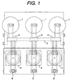
- Fig. 1 is a plan view of the electromagnetic operation device of the present invention
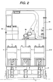
- Fig. 2 is a front view including electromagnetic operators and controller
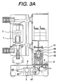
- Fig. 3A and 3B are side view including the main shafts and three-phase connecting shaft.
- the vacuum valve 1 of each phase is connected with the electromagnetic operator 4 via the main shaft 2.
- Each main shaft 2 starts operation freely from other phases, but is connected with others by the three-phase connecting shaft 3 for synchronization.
- the electromagnetic operation device is enclosed in a multi-stage box case 8, where controller including a control board 81 and capacitor 82 are enclosed in the upper stage 8-1 and an electromagnetic operator 4 is enclosed in the middle stage 8-2.
- the upper stage 8-1 can not only be provided above the center electromagnetic operator 4 as shown in the figure but also be provided above other electromagnetic operators 4.
- the control board 81 contains a control logic section that receives a signal of closing command (ON) or opening command (OFF) to the vacuum valve 1 and performs logical operation for controlling the electromagnetic operator 4, charging/discharging circuit for charging and discharging the capacitor 82, relay for controlling the current direction through a coil 43, and contacts.
- a control logic section that receives a signal of closing command (ON) or opening command (OFF) to the vacuum valve 1 and performs logical operation for controlling the electromagnetic operator 4, charging/discharging circuit for charging and discharging the capacitor 82, relay for controlling the current direction through a coil 43, and contacts.
- an "ON" pushbutton for sending a closing command to the vacuum valve 1
- an "OFF" pushbutton for sending an opening command.
- a mechanism for detecting the condition of vacuum valve 1, comprising an auxiliary contact 83, display panel 84 and counter 85, is mounted above the electromagnetic operator 4.
- auxiliary contact section (counter 85, display panel 84, and auxiliary contact 83) of the controller is mounted above the center electromagnetic operator 4 and so designed to operate in line with the electromagnetic operator 4.
- control board 81, capacitor 82, and auxiliary contact section are enclosed in a separate box from the electromagnetic operators, affect of big impact can be reduced. Furthermore, separate wiring for the auxiliary contact section becomes possible and parts replacement of the section becomes easier.
- Fig. 3A shows the OFF state of the vacuum valve 1.
- the electromagnetic operator 4 is equipped with a moving core 41, permanent magnet 42 and coil 43.
- the controller When the controller is turned on the coil 43 is energized, the moving core 41 moves downward together with the rod 44. Since the lower end of the rod 44 is connected with the blade 45 at the fulcrum 46, motion of the rod 44 is transmitted to the main shaft 2. Since the main shaft 2 is connected with the operation rod of the vacuum valve 1 via the blade 45' provided on the other side of the blade 45, the closing operation of the electromagnetic operator 4 is transmitted to the vacuum valve 1 and so the valve contact 11 goes ON.
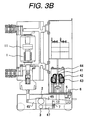
- Fig. 3B shows the ON state of the vacuum valve 1.
- the ON state of the vacuum valve 1 can be kept by the retention force of the permanent magnet 42 as the flux of the permanent magnet 42 flows as shown in a bold line in the figure.
- Fig. 4 is a conceptual figure of the arrangement and connection of the main shafts 2 and three-phase connecting shaft 3.
- Fig. 4(a) is a front view.
- a bar 9 placed above the case 8 supports each main shaft 2 so as to ensure rotation, below which a solid lubricant 31 holds the three-phase connecting shaft 3.
- Fig. 4(b) shows the main shaft 2 supported in a different manner, where a partition 81 formed on the case 8 is provided between each phase and each main shaft 2 is supported by the partition 81.
- Fig. 4(c) is a side view, showing the connection between the main shaft 2 and three-phase connecting shaft 3. Because of this connection, in case of variation in the closing or opening operation, the motion of the main shaft 2 of a phase that has operated quicker than the others is transmitted to the connecting shaft 3 and the three-phase connecting shaft 3 so operates as to hasten the operation of the main shaft 2 of slow phases. To speak from an opposite viewpoint, the main shaft 2 of slowly operating phase restricts the motion of the main shaft 2 of quickly operating phase.
- the center electromagnetic operator 4 is provided with a stopper 5 and the other electromagnetic operators 4 are each provided with a shock absorber 6.
- shock absorbers 6 on both sides where no deflection is caused, and by dispersing a force like the above, smaller shock absorber becomes applicable.
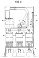
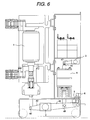
- Fig. 5 and Fig. 6 show an embodiment where the three-phase connecting shaft 3 is provided above the electromagnetic operator 4.
- the three-phase connecting shaft 3 is provided above the electromagnetic operator 4 and the main shaft 2 is provided below the electromagnetic operator 4.
- the two shafts are connected via the rod 44 of the electromagnetic operator 4. That is to say, because the rod 44 is connected with the blade 45 of the main shaft 2 at the fulcrum 46, the motion of the rod 44 is transmitted to the blade 47 of the three-phase connecting shaft 3. Accordingly, the three-phase connecting shaft 3 can synchronize the operation of the main shafts 3 of each phase.
- Fig. 7 shows an embodiment where the three-phase connecting shaft 3 is provided on the vacuum valve 1 side. This differs from the first embodiment in a point that the three-phase connecting shaft 3 is provided on the vacuum valve 1 side below the main shaft 2.
- the linkage 7 is provided between the blade 45' on the vacuum valve 1 side of the main shaft and blade 47 of the three-phase connecting shaft. Linkage operation is the same as in the fist embodiment.
- the first and third embodiments allow easier installation and adjustment because the main shafts and three-phase connecting shafts are provided in the same portion of the case.
- the second embodiment is advantageous in case space is available above the electromagnetic operator because a linkage for connecting two blades with each other is no longer necessary.
Landscapes
- Physics & Mathematics (AREA)
- Electromagnetism (AREA)
- Driving Mechanisms And Operating Circuits Of Arc-Extinguishing High-Tension Switches (AREA)
- Manipulator (AREA)
Abstract

Description
- The present invention relates to an electromagnetic operation device, particularly to the electromagnetic operation device that is suitable for switching a switch such as circuit breaker with the aid of electromagnetic force.
- To operate a switch such as circuit breaker, an electromagnetic operator that switches with the aid of electromagnetic force generated by electromagnet is utilized (see Japanese Patent Laid-open No. 2002-217026).
- There is also available a hybrid type operator on which electromagnetic suction force of electromagnet is used to close the switch and permanent magnet is employed to keep the switch on (see Japanese Patent Laid-open No. 2001-216875).
- When the above electromagnetic operator is used for vacuum valve in a three-phase power system, the electromagnetic operator is usually paired one-to-one with vacuum valve of each phase by a main shaft, but lag may be caused in the operation of the electromagnetic operator because of the variation of each phase. Consequently, there arises a problem that the opening timing of vacuum valve of each phase varies and so stable opening of the power system cannot be achieved.
- In addition, the size of the electromagnetic operator and its controller has become larger as electromagnet has become larger, which resultantly disables space saving.
- In view of the above problems associated with the prior art, an object of the present invention is to offer an electromagnetic operation device that can absorb variation of each phase. Another object is to offer an electromagnetic operation device that encloses its own parts and components efficiently.
- To achieve the above objects, the present invention is an electromagnetic operation device comprises a main shaft that can operate for each phase and a connecting shaft that synchronizes the operation of the main shafts of three phases.
- According to the present invention, even in case the main shaft connected with the vacuum valve of each phase operates differently and one of the main shafts operates quicker than the others, lag of each phase can be absorbed and so the vacuum valve can be opened stably because the electromagnetic operation device is equipped with a three-phase connecting shaft that enables the other main shafts to follow the quicker main shaft.
-
- Fig. 1 shows a plan view of the electromagnetic operation device according to the first embodiment and vacuum valve.
- Fig. 2 shows a front view of the electromagnetic operation device according to the first embodiment.
- Fig. 3A shows a side view of the arrangement in the OFF state in the first embodiment.
- Fig. 3B shows a side view of the arrangement in the ON state in the first embodiment.
- Fig. 4 is a brief figure showing the arrangement and connection of the main shafts and three-phase connecting shaft.
- Fig. 5 shows a front view of the electromagnetic operation device according to the second embodiment.
- Fig. 6 shows a side view of the electromagnetic operation device according to the second embodiment.
- Fig. 7 shows a side view of the electromagnetic operation device according to the third embodiment.
- Embodiments of the present invention are described hereunder, using figures. In the figures, the same symbol represents the same component.
- Fig. 1 is a plan view of the electromagnetic operation device of the present invention; Fig. 2 is a front view including electromagnetic operators and controller; Fig. 3A and 3B are side view including the main shafts and three-phase connecting shaft.
- As shown in Fig. 1, the
vacuum valve 1 of each phase is connected with theelectromagnetic operator 4 via themain shaft 2. Eachmain shaft 2 starts operation freely from other phases, but is connected with others by the three-phase connecting shaft 3 for synchronization. - As shown in Fig. 2, the electromagnetic operation device is enclosed in a
multi-stage box case 8, where controller including acontrol board 81 andcapacitor 82 are enclosed in the upper stage 8-1 and anelectromagnetic operator 4 is enclosed in the middle stage 8-2. The upper stage 8-1 can not only be provided above the centerelectromagnetic operator 4 as shown in the figure but also be provided above otherelectromagnetic operators 4. - The
control board 81 contains a control logic section that receives a signal of closing command (ON) or opening command (OFF) to thevacuum valve 1 and performs logical operation for controlling theelectromagnetic operator 4, charging/discharging circuit for charging and discharging thecapacitor 82, relay for controlling the current direction through acoil 43, and contacts. In addition, there are provided an "ON" pushbutton for sending a closing command to thevacuum valve 1 and an "OFF" pushbutton for sending an opening command. A mechanism for detecting the condition ofvacuum valve 1, comprising anauxiliary contact 83,display panel 84 andcounter 85, is mounted above theelectromagnetic operator 4. - As explained above, the auxiliary contact section (
counter 85,display panel 84, and auxiliary contact 83) of the controller is mounted above the centerelectromagnetic operator 4 and so designed to operate in line with theelectromagnetic operator 4. In addition, since thecontrol board 81,capacitor 82, and auxiliary contact section are enclosed in a separate box from the electromagnetic operators, affect of big impact can be reduced. Furthermore, separate wiring for the auxiliary contact section becomes possible and parts replacement of the section becomes easier. - Fig. 3A shows the OFF state of the
vacuum valve 1. Theelectromagnetic operator 4 is equipped with a movingcore 41,permanent magnet 42 andcoil 43. When the controller is turned on thecoil 43 is energized, the movingcore 41 moves downward together with therod 44. Since the lower end of therod 44 is connected with theblade 45 at thefulcrum 46, motion of therod 44 is transmitted to themain shaft 2. Since themain shaft 2 is connected with the operation rod of thevacuum valve 1 via the blade 45' provided on the other side of theblade 45, the closing operation of theelectromagnetic operator 4 is transmitted to thevacuum valve 1 and so thevalve contact 11 goes ON. - Fig. 3B shows the ON state of the
vacuum valve 1. The ON state of thevacuum valve 1 can be kept by the retention force of thepermanent magnet 42 as the flux of thepermanent magnet 42 flows as shown in a bold line in the figure. - On the other hand, when a reverse current runs through the
coil 43 upon the opening operation of the controller, since the flux generated by thecoil 43 becomes opposite to that of thepermanent magnet 42 and so the suction force of the movingcore 41 becomes less than the elastic force of a spring (not shown), the movingcore 41 moves upward. Accordingly, a reverse operation to the above is performed via themain shaft 2 that connects the vacuum valve one-to-one with theelectromagnetic operator 4, and thevalve contact 11 goes OFF. - When one
vacuum valve 1 is paired with oneelectromagnetic operator 4, variation in the operation of theelectromagnetic operator 4 causes lag in the closing and opening timing of thevacuum valve 1 of each phase. To prevent this, a three-phase connecting shaft 3 is provided below eachmain shaft 2 and eachmain shaft 2 is connected with the three-phase connecting shaft 3 via thelinkage 7. - Fig. 4 is a conceptual figure of the arrangement and connection of the
main shafts 2 and three-phase connecting shaft 3. Fig. 4(a) is a front view. Abar 9 placed above thecase 8 supports eachmain shaft 2 so as to ensure rotation, below which asolid lubricant 31 holds the three-phase connecting shaft 3. Fig. 4(b) shows themain shaft 2 supported in a different manner, where apartition 81 formed on thecase 8 is provided between each phase and eachmain shaft 2 is supported by thepartition 81. - Fig. 4(c) is a side view, showing the connection between the
main shaft 2 and three-phase connecting shaft 3. Because of this connection, in case of variation in the closing or opening operation, the motion of themain shaft 2 of a phase that has operated quicker than the others is transmitted to the connectingshaft 3 and the three-phase connecting shaft 3 so operates as to hasten the operation of themain shaft 2 of slow phases. To speak from an opposite viewpoint, themain shaft 2 of slowly operating phase restricts the motion of themain shaft 2 of quickly operating phase. - According to the above embodiment, since the contacting time lag of the
valve contact 11 due to the variation in the operation of theelectromagnetic operator 4 of each phase can be reduced and the operation of the three phases can be synchronized by the three-phase connecting shaft 3 connecting eachelectromagnetic operator 4, stable closing and opening operation of the power system becomes available. In addition, in case of using multiple electromagnetic operators, imbalanced load to the shaft due to the variation in the operation ofelectromagnetic operators 4 can be reduced because amain shaft 2 that enables independent operation of each phase is employed. - In opening the
vacuum valve 1, it is necessary to absorb impact applied to themain shaft 2 upon the opening and stop the motion of the valve quickly. As shown in Fig. 1 and Fig. 3A, of the three-phaseelectromagnetic operators 4 in this embodiment, the centerelectromagnetic operator 4 is provided with astopper 5 and the otherelectromagnetic operators 4 are each provided with ashock absorber 6. - In the construction in Fig. 1, since the center
main shaft 2 deflects more than the other twomain shafts 2, quick absorption cannot be expected if an impact is first given to the center. Accordingly, the impact is absorbed by theshock absorber 6 on both sides first of all, and then the motion is stopped by thecenter stopper 5 installed at a limit position. - According to this embodiment, impact can be absorbed quickly and well in balance by the
shock absorbers 6 on both sides where no deflection is caused, and by dispersing a force like the above, smaller shock absorber becomes applicable. - Next, the second embodiment of the present invention is described hereunder. Fig. 5 and Fig. 6 show an embodiment where the three-
phase connecting shaft 3 is provided above theelectromagnetic operator 4. - The three-
phase connecting shaft 3 is provided above theelectromagnetic operator 4 and themain shaft 2 is provided below theelectromagnetic operator 4. The two shafts are connected via therod 44 of theelectromagnetic operator 4. That is to say, because therod 44 is connected with theblade 45 of themain shaft 2 at thefulcrum 46, the motion of therod 44 is transmitted to theblade 47 of the three-phase connecting shaft 3. Accordingly, the three-phase connecting shaft 3 can synchronize the operation of themain shafts 3 of each phase. - Next, the third embodiment of the present invention is described hereunder. Fig. 7 shows an embodiment where the three-
phase connecting shaft 3 is provided on thevacuum valve 1 side. This differs from the first embodiment in a point that the three-phase connecting shaft 3 is provided on thevacuum valve 1 side below themain shaft 2. Thelinkage 7 is provided between the blade 45' on thevacuum valve 1 side of the main shaft andblade 47 of the three-phase connecting shaft. Linkage operation is the same as in the fist embodiment. - While any of the three embodiments described above shall be selected in accordance with the arrangement of the electromagnetic operation device, the first and third embodiments allow easier installation and adjustment because the main shafts and three-phase connecting shafts are provided in the same portion of the case. On the other hand, the second embodiment is advantageous in case space is available above the electromagnetic operator because a linkage for connecting two blades with each other is no longer necessary.
Claims (9)
- An electromagnetic operation device, comprising three vacuum valves for three phases and three electromagnetic operators paired with said vacuum valves, further comprising:three main shafts that can operate independently for each phase; anda three-phase connecting shaft for synchronizing the operation of said three main shafts in accordance with the operation of each main shaft.
- The electromagnetic operation device according to Claim 1, wherein respective said three main shafts are provided below respective said three electromagnetic operators and said three-phase connecting shaft is provided below said three main shafts so that the motion of any one of the main shafts is transmitted to the other main shaft via said three-phase connecting shaft.
- The electromagnetic operation device according to Claim 1, wherein respective said three main shafts are provided below respective said three electromagnetic operators and said three-phase connecting shaft is provided above said three electromagnetic operators so that the motion of any one of the main shafts is transmitted to the other main shaft via said three-phase connecting shaft.
- The electromagnetic operation device according to Claim 3, wherein said three main shafts are connected with said three-phase connecting shaft via the rods of said three electromagnetic operators.
- The electromagnetic operation device according to Claim 1, wherein respective said three main shafts are provided below respective said three electromagnetic operators and said three-phase connecting shaft is provided below said vacuum valves so that the motion of any one of the main shafts is transmitted to the other main shaft via said three-phase connecting shaft.
- The electromagnetic operation device according to Claim 5, wherein said three main shafts are connected with said three-phase connecting shaft via the blades on the vacuum valve side of the main shafts.
- The electromagnetic operation device according to Claim 1, wherein controller of said three electromagnetic operator, including control board, capacitor and auxiliary contact, is enclosed in a separate box that is separated from a box enclosing said three electromagnetic operators.
- The electromagnetic operation device according to Claim 7, wherein said separate box enclosing said controller is so constructed as to be replaceable separately from said electromagnetic operators.
- The electromagnetic operation device according to claim 1, wherein, of said three electromagnetic operators, the center electromagnetic operator is provided with a stopper and the other electromagnetic operators are each provided with a shock absorber.
Applications Claiming Priority (1)
| Application Number | Priority Date | Filing Date | Title |
|---|---|---|---|
| JP2004215789A JP4358698B2 (en) | 2004-07-23 | 2004-07-23 | Electromagnetic operation device |
Publications (2)
| Publication Number | Publication Date |
|---|---|
| EP1619708A2 true EP1619708A2 (en) | 2006-01-25 |
| EP1619708A3 EP1619708A3 (en) | 2006-08-23 |
Family
ID=35149391
Family Applications (1)
| Application Number | Title | Priority Date | Filing Date |
|---|---|---|---|
| EP05015896A Withdrawn EP1619708A3 (en) | 2004-07-23 | 2005-07-21 | Electromagnetic operation device |
Country Status (6)
| Country | Link |
|---|---|
| US (1) | US20060028073A1 (en) |
| EP (1) | EP1619708A3 (en) |
| JP (1) | JP4358698B2 (en) |
| KR (1) | KR20060046578A (en) |
| CN (1) | CN1725407A (en) |
| TW (1) | TWI282572B (en) |
Cited By (3)
| Publication number | Priority date | Publication date | Assignee | Title |
|---|---|---|---|---|
| DE19959794B4 (en) * | 1999-12-07 | 2009-09-17 | Siemens Ag | Contact drive for vacuum switch |
| EP2148348A1 (en) * | 2008-07-22 | 2010-01-27 | Hitachi Ltd. | Switching apparatus |
| CN101667505B (en) * | 2009-07-16 | 2013-11-20 | 东莞市广安电气检测中心有限公司 | Heavy-current phase control closing device |
Families Citing this family (16)
| Publication number | Priority date | Publication date | Assignee | Title |
|---|---|---|---|---|
| JP4492610B2 (en) * | 2006-12-28 | 2010-06-30 | 株式会社日立製作所 | Circuit breaker and its switching method |
| JP5033044B2 (en) * | 2008-04-16 | 2012-09-26 | 三菱電機株式会社 | switchboard |
| JP4611408B2 (en) * | 2008-07-22 | 2011-01-12 | 株式会社日立製作所 | Switch operating device |
| JP5275301B2 (en) * | 2010-08-12 | 2013-08-28 | 株式会社日立製作所 | Air circuit breaker |
| JP5579323B2 (en) | 2011-07-07 | 2014-08-27 | 三菱電機株式会社 | Electromagnetic operation device |
| JP5872388B2 (en) * | 2012-06-18 | 2016-03-01 | 株式会社日立製作所 | Operating device or vacuum switch |
| JP5883728B2 (en) * | 2012-06-18 | 2016-03-15 | 株式会社日立製作所 | Assembling method of operating device, vacuum switchgear or operating device. |
| JP6216529B2 (en) * | 2013-03-28 | 2017-10-18 | 株式会社日立産機システム | Railway vehicle |
| CN103236357A (en) * | 2013-05-09 | 2013-08-07 | 苏州朗格电气有限公司 | Novel switchgear |
| CN103295809A (en) * | 2013-05-09 | 2013-09-11 | 苏州朗格电气有限公司 | Novel switching-on switching-off separation coupler for switch equipment |
| JP6106528B2 (en) * | 2013-06-05 | 2017-04-05 | 株式会社日立産機システム | Contactor operation device |
| KR101497648B1 (en) * | 2013-07-02 | 2015-03-03 | (주)에스엔 | VARIABLE ElECTRIC LOAD |
| ES2618532T3 (en) * | 2013-11-06 | 2017-06-21 | Lsis Co., Ltd. | Circuit breaker |
| JP2018147642A (en) * | 2017-03-03 | 2018-09-20 | 株式会社日立産機システム | Electromagnetic operating device and electromagnetic operating switchgear |
| JP6676226B1 (en) * | 2019-05-22 | 2020-04-08 | 三菱電機株式会社 | Electromagnetic operating device |
| ES1243729Y1 (en) | 2020-02-19 | 2021-04-28 | Quijada Pablo Paunero | SAFETY DEVICE AND TRIPOLAR BASE |
Citations (2)
| Publication number | Priority date | Publication date | Assignee | Title |
|---|---|---|---|---|
| JP2001216875A (en) | 2000-02-04 | 2001-08-10 | Hitachi Ltd | Circuit breaker and electromagnetic actuator for circuit breaker |
| JP2002217026A (en) | 2001-01-18 | 2002-08-02 | Hitachi Ltd | Electromagnet and operation mechanism of switchgear using the same |
Family Cites Families (5)
| Publication number | Priority date | Publication date | Assignee | Title |
|---|---|---|---|---|
| JPS55157823A (en) * | 1979-05-29 | 1980-12-08 | Tokyo Shibaura Electric Co | Vacuum contactor |
| JP2002033034A (en) * | 2000-07-13 | 2002-01-31 | Hitachi Ltd | Switchgear and system switching device using the same |
| CN1234135C (en) * | 2001-01-18 | 2005-12-28 | 株式会社日立制作所 | Electromagnetic and operating mechanism of switch using said electromagnet |
| JP2002216594A (en) * | 2001-01-19 | 2002-08-02 | Hitachi Ltd | Switchgear operation mechanism |
| EP1416503B1 (en) * | 2002-10-30 | 2013-09-18 | Hitachi, Ltd. | Solenoid-operated switching device and control device for electromagnet |
-
2004
- 2004-07-23 JP JP2004215789A patent/JP4358698B2/en not_active Expired - Fee Related
-
2005
- 2005-05-24 TW TW094116938A patent/TWI282572B/en not_active IP Right Cessation
- 2005-07-14 US US11/180,553 patent/US20060028073A1/en not_active Abandoned
- 2005-07-15 CN CNA2005100842049A patent/CN1725407A/en active Pending
- 2005-07-21 EP EP05015896A patent/EP1619708A3/en not_active Withdrawn
- 2005-07-22 KR KR1020050066627A patent/KR20060046578A/en not_active Withdrawn
Patent Citations (2)
| Publication number | Priority date | Publication date | Assignee | Title |
|---|---|---|---|---|
| JP2001216875A (en) | 2000-02-04 | 2001-08-10 | Hitachi Ltd | Circuit breaker and electromagnetic actuator for circuit breaker |
| JP2002217026A (en) | 2001-01-18 | 2002-08-02 | Hitachi Ltd | Electromagnet and operation mechanism of switchgear using the same |
Cited By (3)
| Publication number | Priority date | Publication date | Assignee | Title |
|---|---|---|---|---|
| DE19959794B4 (en) * | 1999-12-07 | 2009-09-17 | Siemens Ag | Contact drive for vacuum switch |
| EP2148348A1 (en) * | 2008-07-22 | 2010-01-27 | Hitachi Ltd. | Switching apparatus |
| CN101667505B (en) * | 2009-07-16 | 2013-11-20 | 东莞市广安电气检测中心有限公司 | Heavy-current phase control closing device |
Also Published As
| Publication number | Publication date |
|---|---|
| TW200620359A (en) | 2006-06-16 |
| KR20060046578A (en) | 2006-05-17 |
| EP1619708A3 (en) | 2006-08-23 |
| TWI282572B (en) | 2007-06-11 |
| JP4358698B2 (en) | 2009-11-04 |
| JP2006040615A (en) | 2006-02-09 |
| US20060028073A1 (en) | 2006-02-09 |
| CN1725407A (en) | 2006-01-25 |
Similar Documents
| Publication | Publication Date | Title |
|---|---|---|
| EP1619708A2 (en) | Electromagnetic operation device | |
| KR101250166B1 (en) | Air circuit breaker | |
| JP2743989B2 (en) | Switching device | |
| EP2871651B1 (en) | Circuit breaker | |
| US6130594A (en) | Magnetically driven electric switch | |
| US20070253124A1 (en) | Circuit interrupter including point-on-wave controller and voltage sensors | |
| EP4000085B1 (en) | Relay | |
| JP4277198B2 (en) | Vacuum switchgear | |
| US5834725A (en) | Circuit interrupter arrangement | |
| US20130146565A1 (en) | Power switchgear | |
| JP2019096575A (en) | Vacuum circuit breaker | |
| JP2009059542A (en) | Power switchgear and gas insulated circuit breaker | |
| KR101310849B1 (en) | Circuit breaker | |
| JPWO2011086670A1 (en) | Electromagnetic operation switchgear | |
| JP2017224517A (en) | Actuator for gas-insulated switchgear and gas-insulated switchgear using the same | |
| CA1230627A (en) | Vacuum contactor with kickout spring | |
| JP6522265B1 (en) | Circuit breaker | |
| KR20100095747A (en) | A cell switch operating rod for cubicle | |
| JP4356013B2 (en) | Electromagnetic switchgear | |
| CN205282381U (en) | Permanent magnetic actuator | |
| KR100844274B1 (en) | 3-position switch structure of high pressure vacuum magnetic contactor | |
| KR102476858B1 (en) | Load break switch capable of pma manipulation | |
| JPS61171017A (en) | Breaker | |
| EP4105958B1 (en) | Circuit breaker | |
| EP3955273B1 (en) | Electromagnetic operating apparatus |
Legal Events
| Date | Code | Title | Description |
|---|---|---|---|
| PUAI | Public reference made under article 153(3) epc to a published international application that has entered the european phase |
Free format text: ORIGINAL CODE: 0009012 |
|
| AK | Designated contracting states |
Kind code of ref document: A2 Designated state(s): AT BE BG CH CY CZ DE DK EE ES FI FR GB GR HU IE IS IT LI LT LU LV MC NL PL PT RO SE SI SK TR |
|
| AX | Request for extension of the european patent |
Extension state: AL BA HR MK YU |
|
| 17P | Request for examination filed |
Effective date: 20060331 |
|
| PUAL | Search report despatched |
Free format text: ORIGINAL CODE: 0009013 |
|
| AK | Designated contracting states |
Kind code of ref document: A3 Designated state(s): AT BE BG CH CY CZ DE DK EE ES FI FR GB GR HU IE IS IT LI LT LU LV MC NL PL PT RO SE SI SK TR |
|
| AX | Request for extension of the european patent |
Extension state: AL BA HR MK YU |
|
| AKX | Designation fees paid |
Designated state(s): DE FR GB |
|
| 17Q | First examination report despatched |
Effective date: 20070419 |
|
| STAA | Information on the status of an ep patent application or granted ep patent |
Free format text: STATUS: THE APPLICATION IS DEEMED TO BE WITHDRAWN |
|
| 18D | Application deemed to be withdrawn |
Effective date: 20070830 |