EP1619686A2 - Disk housing case - Google Patents
Disk housing case Download PDFInfo
- Publication number
- EP1619686A2 EP1619686A2 EP05015783A EP05015783A EP1619686A2 EP 1619686 A2 EP1619686 A2 EP 1619686A2 EP 05015783 A EP05015783 A EP 05015783A EP 05015783 A EP05015783 A EP 05015783A EP 1619686 A2 EP1619686 A2 EP 1619686A2
- Authority
- EP
- European Patent Office
- Prior art keywords
- index
- disk
- case
- disk housing
- disk tray
- Prior art date
- Legal status (The legal status is an assumption and is not a legal conclusion. Google has not performed a legal analysis and makes no representation as to the accuracy of the status listed.)
- Withdrawn
Links
Images


Classifications
-
- G—PHYSICS
- G11—INFORMATION STORAGE
- G11B—INFORMATION STORAGE BASED ON RELATIVE MOVEMENT BETWEEN RECORD CARRIER AND TRANSDUCER
- G11B33/00—Constructional parts, details or accessories not provided for in the other groups of this subclass
- G11B33/02—Cabinets; Cases; Stands; Disposition of apparatus therein or thereon
- G11B33/04—Cabinets; Cases; Stands; Disposition of apparatus therein or thereon modified to store record carriers
- G11B33/0405—Cabinets; Cases; Stands; Disposition of apparatus therein or thereon modified to store record carriers for storing discs
- G11B33/0411—Single disc boxes
- G11B33/0422—Single disc boxes for discs without cartridge
- G11B33/0427—Single disc boxes for discs without cartridge comprising centre hole locking means
-
- Y—GENERAL TAGGING OF NEW TECHNOLOGICAL DEVELOPMENTS; GENERAL TAGGING OF CROSS-SECTIONAL TECHNOLOGIES SPANNING OVER SEVERAL SECTIONS OF THE IPC; TECHNICAL SUBJECTS COVERED BY FORMER USPC CROSS-REFERENCE ART COLLECTIONS [XRACs] AND DIGESTS
- Y10—TECHNICAL SUBJECTS COVERED BY FORMER USPC
- Y10S—TECHNICAL SUBJECTS COVERED BY FORMER USPC CROSS-REFERENCE ART COLLECTIONS [XRACs] AND DIGESTS
- Y10S206/00—Special receptacle or package
- Y10S206/804—Special receptacle or package with means to lift or draw out content
-
- Y—GENERAL TAGGING OF NEW TECHNOLOGICAL DEVELOPMENTS; GENERAL TAGGING OF CROSS-SECTIONAL TECHNOLOGIES SPANNING OVER SEVERAL SECTIONS OF THE IPC; TECHNICAL SUBJECTS COVERED BY FORMER USPC CROSS-REFERENCE ART COLLECTIONS [XRACs] AND DIGESTS
- Y10—TECHNICAL SUBJECTS COVERED BY FORMER USPC
- Y10S—TECHNICAL SUBJECTS COVERED BY FORMER USPC CROSS-REFERENCE ART COLLECTIONS [XRACs] AND DIGESTS
- Y10S206/00—Special receptacle or package
- Y10S206/815—Finger opening
Definitions
- the present invention relates to a disk housing case for housing recording media disks, such as CD's, DVD's, and BD's, and particularly to entry/exit structure of indexes therefor.
- Japanese Unexamined Patent Publication No. 10(1998)-106203 discloses a widely used disk housing case, for housing recording media disks, such as CD's (Compact Discs), DVD's (Digital Versatile Discs), and BD' s (Blu-ray Discs).
- This disk housing case comprises: a disk tray, for removably holding the recording media disk; and a pair of case halves, which are linked to each other at one of the ends thereof to be openable and closable, for housing the disk tray.
- the disk tray is fitted into a rear case half from the pair of case halves.
- a front index and a rear index are attached to the front case half and the inner surface of the rear case half.
- Japanese Utility Model No. 3094214 discloses a disk housing case, to which no indexes are attached.
- an index portion which is formed as a rough surface, is provided on the outer surface of a case half, to enable writing and editing of content on the index portion with a pencil or the like.
- the amount of information capable of being recorded by writing and editing of content on the roughened index portion is limited, and the index portion is not aesthetically pleasing.
- the present invention has been developed in view of these circumstances. It is an object of the present invention to provide a disk housing case that enables insertion and removal of an index, which is interposed between a disk tray and a case half into which the disk tray is fitted, without removing the disk tray from the case half.
- the disk housing case of the present invention comprises:
- the disk tray comprises: a substantially discoid disk housing recess, where the recording media disk is fitted into and housed; and a flared portion that extends toward the exterior of the disk housing recess; protrusive ribs, for pressing the index toward the case half, are provided on the flared portion; and the direction in which the ribs extend is parallel to the insertion/removal direction of the index.
- An index entry/exit opening is provided at a linked side or at an end opposite the liked side of the pair of case halves in the disk housing case of the present invention.
- a contact opening for enabling a finger or an index sliding member to contact the index to insert and remove the index, is provided in the disk tray and/or the case half, in which the disk tray is fitted.
- the index can be slid by contacting it with a finger or the like through the contact opening, while the disk tray is mounted in the case half, and the index can be inserted or removed through the index entry/exit opening. Accordingly, insertion and removal of an index, which is interposed between a disk tray and a case half into which the disk tray is fitted, are enabled without removing the disk tray from the case half.
- the disk housing case of the first embodiment is a case for housing a recording media disk, such as CD's (Compact Discs), DVD's (Digital Versatile Discs), andBD's (Blu-ray Discs).
- the first embodiment is characterized by the entry/exit structure of indexes.
- Figure 1 is an exploded perspective view of a disk housing case 1 in a closed state.
- Figures 2A and 2B are perspective views of the disk housing case 1 in a closed state (a front case half is omitted in Figure 2B).
- Figure 3 is a plan view of the disk housing case 1 in an open state.
- Figure 4 is a bottom view of the disk housing case 1 in an open state.
- Figure 5A is a front view of the disk housing case 1 (a rear view is the same as the front view, and therefore is omitted).
- Figure 5B is a sectional view taken along line V-V of Figure 3.
- Figure 5C is a magnified partial view of an end F of Figure 5B.
- Figure 6A is a left side view of the disk housing case 1
- Figure 6B is a right side view of the disk housing case 1.
- a recording medium disk 2 and indexes 41 and 42 are omitted from the figures as appropriate.
- the disk housing case 1 of the present embodiment comprises: a disk tray 10, for removably holding the recording medium disk 2; a front case half 20; and a rear case half 30.
- the front case half 20 and the rear case half 30 are openable and closable, and the disk tray 10 is housed therein.
- the pair of case halves 20 and 30 are arranged such that they face each other with the disk tray 10 therebetween, and are linked at the left side ends (first ends) thereof in Figure 1.
- the disk tray 10 is removably fitted into the rear case half 30.
- the disk tray 10 and the case halves 20 and 30 that house the disk tray 10 are substantially rectangular in plan view, are formed of the same or different types of resin, with colors or patterns as desired. However, regarding at least the case halves 20 and 30, it is preferable that they are transparent, considering the need to visual recognize the contents of indexes.
- a front side index 41 is interposed between the front case half 20 and the disk tray 10, and a rear side index 42 is interposed between the rear case half 30 and the disk tray 10.
- the indexes 41 and 42 are in the form of cards or booklets.
- the disk housing case 1 of the present embodiment is of a construction in which the rear side index 42 is insertable and extractable from the sides of the disk housing case 1. The details of this construction will be described later.
- the insertion/removal direction of the rear side index 42 is denoted by arrow Y in Figure 1.
- the indexes 41 and 42 have, for example, the title of the recording medium disk 2, a photograph, or lines in which the contents of the recording medium disk 2 can be edited, printed thereon.
- the front case half 20 comprises: a plate like main body 21 that faces the disk tray 10; and a pair of side walls 22 that extend in an insertion/removal direction Y of the rear side index 42.
- the side walls 22 extend beyond the main body 21, and the extended portions are link arms 22a that link the front case half 20 with the rear case half 30.
- the rear case half 30 comprises: a plate like main body 31 that faces the disk tray 10; and a pair of side walls 32 that extend in the insertion/removal direction Y of the rear side index 42. Cutout portions 32a are provided at the central portions of the side walls 32, to enable fingers to engage the disk tray 10, thereby facilitating removal thereof from the rear case half 30.
- the areas of the main bodies 21 and 31 of the case halves 20 and 30 are set such that the side walls 22 of the front case half 20 are positioned outside the side walls 32 of the rear case half 30. That is, the areas of the main bodies 21 and 31 are set such that the rear case half 30 can be fitted within the front case half 20.
- Protrusions 22b are provided on the inner surfaces of the pair of link arms 22a that constitute the front case half 20.
- Recesses 32b, for the tips of the protrusions 22b to enter, are provided in the outer surfaces of the pair of side walls 32 that constitute the rear case half 30.
- the pair of case halves 20 and 30 are linked at the first ends (left side ends in Figure 1) thereof such that they are openable and closable, by the front case half 20 being pivotally supported on the rear case half 30 by the pair of protrusions 22b.
- the first ends will be referred to as "link ends" and denoted with reference letter E.
- the ends opposite the first end (right side ends in Figure 1, second ends) will be denoted with reference letter F (refer to Figure 2A).
- the disk tray 10 comprises a tray main body 13, constituted by: a substantially discoid disk housing recess 11, into which the recording medium disk 2 is fitted and housed; and a flared portion 12 that extends toward the exterior of the disk housing recess 11.
- a disk clamper 11a for removably holding a central opening portion of the recording medium disk 2, is provided at the central portion of the disk housing recess 11.
- the flat portion 14b is positioned between the pair of link arms 22a, and becomes coplanar with the main body 21 of the front case half 20 when the pair of case halves 20 and 30 are in a closed state.
- a side wall 15, which is substantially symmetrical with respect to the side wall 14, is provided on the flared portion 12 at the end thereof opposite the link ends of the case halves 20 and 30.
- three substantially semicircular engaging pieces 25, for engaging and holding the front side index 41 are provided on each of the pair of side walls 22 of the front case half 20, parallel to the surface of the main body 21.
- This configuration enables the front side index 41 to be inserted and removed from the open link end E of the front case half 20, by sliding the index 41 between the main body 21 and the engaging pieces 25.
- An arrow X denotes the insertion/removal direction of the front side index 41.
- a side wall 34 is provided at the link end E of the rear case half 30, and recesses 12a, into which the engaging pieces 25 enter, are formed in the flared portion 12 of the disk tray 10.
- protrusive ribs 16 for pressing the rear side index 42 toward the rear case half 30, are provided on the flared portion 12. As illustrated in Figure 3, four protrusive ribs 16 are provided in the vicinity of the corners of the flared portion 12, close to the recesses 12a.
- each protrusive rib 16 is a plate-like protrusions having a trapezoidal surface 16a that constricts from the side of the front case half 20 to the side of the rear case half 30.
- the direction that the protrusive ribs 16 extend is parallel to the insertion/removal direction Y of the rear side index 42.
- a slit 50 which is an index entry/exit opening through which the rear side index 42 is inserted and removed, is provided at the end F, opposite from the link end E of the pair of case halves 20 and 30.
- a side wall 23 is provided at the end F of the front case half 20.
- the side wall 23 is formed to be lower than the side walls 22, which extend parallel to the insertion/removal direction Y of the rear side index 42.
- the slit 50 is formed between the side wall 23 and the main body 31 of the rear case half 30 when the pair of case halves 20 and 30 are in a closed state.
- the height of the side wall 23 is set such that the height of the slit 50 is greater than the thickness of the rear side index 42, while preventing entry of dust and the like into the disk housing case 1.
- contact openings 51 for enabling a finger, preferably a thumb, or an index sliding member, such as a pen, to contact the rear side index 42 to insert and remove the index, are provided in the disk tray 10.
- the contact openings 51 are provided at two locations in the disk tray 10, toward the side of the slit 50. Both of the contact openings 51 are formed so as to straddle the disk housing recess 11 and the flared portion 12 of the disk tray 10.
- the rear side index 42 is inserted and removed in the following manner. First, the pair of case halves 20 and 30 are opened. Then, the recording media disk is removed. Next, a finger or an index sliding member is caused to contact the rear side index 42 through a contact opening 51, to slide the rear side index 42 in or out through the slit 50 (index entry/exit opening) provided at the ends F of the pair of case halves 20 and 30.
- stoppers 35 for preventing inadvertent removal of the rear side index 42, are provided in the rear case half 30 toward the end F, at which the index entry/exit opening is provided.
- the stoppers 35 are ridges provided at the end of the main body 31 of the rear case half 30.
- the stoppers 35 are formed at the right and left sides of the central portion of the end F, when viewed from the index entry/exit opening.
- Reference letters S1 and S2 denote the regions at which the stoppers 35 are formed.
- the stoppers 35 are integrally formed with the main body 31 of the rear case half 30.
- the height H1 of the stoppers 35 is set such that not insertion and removal of the rear side index 42 is not greatly impeded, while inadvertent removal thereof is prevented.
- the height H1 is greater than a thickness H2 of the rear side index 42 and less than a distance H3 between the flared portion 12 of the disk tray 10 and the main body 31 of the rear case half 30.
- the disk housing case 1 of the present embodiment is constructed as described above.
- the disk housing case 1 of the present embodiment is of a construction, in which: the slit 50, which is the index entry/exit opening, is provided in the pair of case halves 20 and 30 at the ends F thereof, which is opposite to the link ends; and the contact openings 51, for enabling a finger or an index sliding member to contact the rear side index 42 to insert and remove the index, are provided in the disk tray 10.
- a finger can contact the rear side index 42 through a contact opening 51 to slide the rear side index 42 while the disk tray 10 is fitted in the rear case half 30.
- the rear side index 42 can be inserted and removed through the slit 50, provided at the ends F of the pair of case halves 20 and 30. Accordingly, insertion and removal of the rear side index 42, which is interposed between the disk tray 10 and the rear case half 30, in which the disk tray 10 is fitted, can be realized without removing the disk tray 10 from the rear case half 30.
- the protrusive ribs 16 are provided on the flared portion 12 of the disk tray 12 to press the rear side index 42 toward the rear case half 30.
- the direction in which the protrusive ribs 16 extend is parallel to the insertion/removal direction Y of the rear side index 42. This direction is perpendicular to the direction in which protrusive ribs of conventional disk housing cases extend.
- the width of the portion of the protrusive ribs 16 that the rear side index passes through is small when viewed from the index entry/exit opening, as illustrated in Figure 6B. Therefore, there is no possibility that sliding motion of the rear side index 42 will be prevented by the presence of the protrusive ribs 16.
- the rear side index 42 can slide smoothly along the direction that the protrusive ribs 16 extend. In this manner, smooth insertion and removal of the rear side index 42 is realized, because the rear side index 42 slides smoothly.
- the stoppers 35 for preventing inadvertent removal of the rear side index 42, are provided in the rear case half 30, toward the end F opposite from the link end thereof. Therefore, there is no possibility that the rear side index 42 will be inadvertently removed through the slit 50, improving the handling properties of the disk housing case 1.
- the stoppers 35 are not formed across the entire end of the main body 31 of the rear case half 30, but are formed on the left and right sides thereof as viewed from the index entry/exit opening and not at the central portion.
- the rear side index 42 is capable of being inserted and removed without riding over the stopper 35 at the central portion. Accordingly, the effect of preventing inadvertent removal of the rear side index 42 is sufficiently secured, while not impeding insertion and removal thereof.
- the slit 50 which is the index entry/exit opening, is formed by not providing a side wall at the end F of the rear case half 30, and by providing the side wall 23, which is shorter than the side walls 22, at the end F of the front case half 20.
- the present invention is not limited to such a configuration.
- the side wall 23 may not be provided at the end F of the front case half 20 and a side wall 33 may be provided at the end F of the rear case half 30 having the slit 50 formed therein, as illustrated in Figure 7.
- two contact openings 51 are provided in the disk tray 10 toward the side of the index entry/exit opening such that they straddle the disk housing recess 11 and the flared portion 12.
- both thumbs can contact the rear side index 42 through the contact openings 51.
- the areas of the contact openings are comparatively large, fingers can move within the contact openings 51, facilitating insertion and removal of the rear side index 42.
- contact openings 51 are not limited to those of the first embodiment, and may be set as appropriate.
- Figures 8A, 8B, 8C, 8D, 8E, and 8F illustrate other formation patterns of the contact openings 51.
- Figures 8A, 8B, 8C, and 8F illustrate examples in which the contact openings 51 are formed only in the flared portions 12 of the disk tray 10.
- the contact openings 51 are not formed in the disk housing recess 11. Therefore, the rear side index 42 can be inserted and removed without removing the recording medium disk 2 from the disk tray 10.
- the example of Figure 8C is preferable.
- the contact openings 51 are provided toward the side of the index entry/exit opening and toward the side of the link ends, facilitating insertion of the sub index portion.
- the contact opening 51 is open toward the index entry/exit opening. Therefore, the edge of the rear side index 42 can be directly grasped during insertion and removal.
- FIGs 8D and 8E illustrate examples in which the contact openings are provided only in the disk housing recess 11 of the disk tray 10.
- the contact openings 51 are not exposed when the recording medium disk 2 is housed in the disk housing recess 11. Therefore, index preservation properties (anti soil properties, anti corrosionproperties, and the like) are favorable.
- the contact openings 51 are not exposed to users when the recording medium disk 2 is housed in the disk housing recess 11. Therefore, the outer appearance of the disk housing case 1 in an open state is the same as that of conventional disk housing cases, which is preferable in terms of aesthetics.
- marks 60 that indicate the insertion/removal direction Y of the rear side index 42 may be provided on the rear side index 42 at the portions corresponding to the contact openings 51 and/or the disk tray 10.
- the insertion/removal direction Y of the rear side index 42 can be easily recognized by users.
- the contact openings may be provided in the rear case half 30.
- the marks 60 may be provided on the rear side index 42 and/or the rear case half 30.
- the first embodiment is a disk housing case 1, in which the disk tray 10 is fitted only in the rear case half 30.
- the present invention is applicable to disk housing cases, in which the disk tray 10 is fitted in at least one of the pair of case halves 20 and 30.
- FIG. 10 is an exploded perspective view of the disk housing case 3 in a closed state.
- Figures 11A and 11B are perspective views of the disk housing case 3 in a closed state, wherein Figure 11A is a view from the front, and Figure 11B is a view from the rear.
- the disk housing case 3 is configured such that the rear side index 42 is insertable and removable through the slit 50 (index entry/exit opening), which is provided at the ends F opposite to the link ends of the pair of case halves 20 and 30, in a manner similar to that of the first embodiment. That is, similar to the first embodiment, there is no side wall at the end F of the rear case half 30, thereby creating an opening.
- the side wall 23 is provided at the end F of the front case half 20.
- the side wall 23 is formed to be lower than the side walls 22, which extend parallel to the insertion/removal direction Y of the rear side index 42.
- the slit 50 is formed between the side wall 23 and the main body 31 of the rear case half 30 when the pair of case halves 20 and 30 are in a closed state.
- the contact openings were provided in the disk tray 10.
- a contact opening 52 is provided in the rear case half 30, at a position that faces the flared portion 12 of the disk tray.
- the contact opening 52 enables a finger or the like to contact the rear side index 42.
- the contact opening 52 is shaped as a substantially semicircular cutout at the end of the rear case half 30 toward the index entry/exit opening.
- a portion of the rear side index 42 is always exposed through the contact opening 52. Therefore, the portion of the rear side index 42 which is exposed through the contact opening 52 is covered by a surface protective layer 42S, as illustrated in Figure 11B.
- the surface protective layer 42S protects the exposed portion of the rear side index 42, to suppress soiling and damage (peeling of printed matter and the like) thereof. Accordingly, it is preferable that the surface protective layer 42S has anti-soiling and anti-abrasion properties.
- Specific preferred examples include resins, such as polyethylene, polypropylene, polyvinyl chloride, and polystyrene.
- the surface protective layer 42S may be formed, for example, by: (1) coating the index 42 with a liquid that contains resins by a dispensing method; (2) attaching a resin film, formed in the shape of the surface protective layer (a semicircle in the illustrated example) onto the index 42 with an adhesive; or (3) directly attaching a resin film onto the index 42 by laminating or the like.
- the disk housing case 3 of the present embodiment is constructed as described above.
- the disk housing case 3 of the present embodiment is of a construction, in which: the slit 50, which is the index entry/exit opening, is provided in the pair of case halves 20 and 30 at the ends F thereof, which is opposite to the link ends; and the contact openings 52, for enabling a finger or the like to contact the rear side index 42 to insert and remove the index, are provided in the rear case half 30.
- a finger can contact the rear side index 42 through the contact opening 52 to slide the rear side index 42 while the disk tray 10 is fitted in the rear case half 30.
- the rear side index 42 can be inserted and removed through the slit 50, provided at the ends F of the pair of case halves 20 and 30. Accordingly, insertion and removal of the rear side index 42, which is interposed between the disk tray 10 and the rear case half 30, in which the disk tray 10 is fitted, can be realized without removing the disk tray 10 from the rear case half 30.
- the portion of the rear side index 42, which is exposed through the contact opening 52, is covered by the surface protective layer 42S. Therefore, soiling and damage to the exposed portion of the rear side index 42 is suppressed, and the exposed portion is favorably protected.
- the region at which the surface protective layer 42S is formed matches the region at which the contact opening 52 is open. Similar advantageous effects can be obtained as long as at least the portion of the rear side index 42, which is exposed through the contact opening 52, is covered by the surface protective layer 42S.
- the surface protective layer 42S is formed in the minimum required region, from the viewpoint of costs and the degree of freedom in editing the contents of the rear side index 42. That is, it is preferable that the surface protective layer 42S is formed only at the portion of the rear side index 42 which is exposed through the contact opening 52 and the vicinity thereof, that may be exposed due to positional displacement of the rear side index 42 within the rear case half 30.
- the slit 50 which is the index entry/exit opening, is formed by not providing a side wall at the end F of the rear case half 30, and by providing the side wall 23, which is shorter than the side walls 22, at the end F of the front case half 20, similar to the configuration of the first embodiment.
- the present invention is not limited to such a configuration.
- the side wall 23 may not be provided at the end F of the front case half 20 and a side wall 33 may be provided at the end F of the rear case half 30 having the slit 50 formed therein, as illustrated in Figure 7.
- a configuration has been described, in which a single contact opening 52 is formed as a substantially semicircular cutout at the end of the rear case half 30 toward the index entry/exit opening.
- the location, shape, and number of the contact opening 52 are not limited to those of the second embodiment, and can be set as appropriate.
- two contact openings 52 may be provided in the rear case half 30 at portions that face the flared portion 12 of the disk tray 10.
- the contact openings 51 as described in the first embodiment may also be provided in the disk tray 10, in addition to the contact openings 52 in the rear case half 30.
- the rear side index 42 may be of the bent type, comprising: a main index portion that faces the main surface of the rear case half 30 (the surface of the main body 31); and a sub index portion which is viewed from the side opposite that of the link ends of the case halves 20 and 30.
- FIGS 13A, 13B, and 13C are sectional views of disk housing cases in closed states, taken along the thickness directions thereof.
- the sub index portion 42b may be pulled out of the slit 50, then bent 90° such that it is arranged along the outer surface 23a of the side wall 23.
- the sub index portion 42b is not housed within the disk housing case. Therefore, the rear side index 42 can be inserted and removed while the pair of case halves are in a closed state, as in the second embodiment.
- the end 21a of the main body 21 of the front case half 20 and the end 31a of the main body 31 of the rear case half 30 may be caused to protrude slightly beyond the outer surface 23a of the side wall 23.
- This configuration is preferable, because the sub index 42b can be housed within the space formed by the protrusive ends 21a and 31a, thereby protecting the sub index portion 42b.
- a slit 57 is formed in the side wall 23 toward the side of the main body 21.
- the leading end of the sub index portion 42b is bent 90° and inserted into the slit 57. This configuration favorably fixes the leading end of the sub index portion 42b, and suppresses separation thereof from the side wall 23.
- a configuration may be adopted, wherein the sub index portion 42b is arranged along the inner surface of the side wall 23 of the front case half 20.
- the sub index portion 42b may be pulled out of the slit 50 with the pair of case halves 20 and 30 in an open state, prior to inserting or removing the rear side index 42.
- the rear side index 42 may alternatively be of a bent type, comprising: the main index portion 42a; and a sub index portion 42c which is arranged to face the side wall 34 of the rear case half 30, to be viewed from the link ends of the pair of case halves 20 and 30.
- Figures 14A and 14B are sectional views of a disk housing case in a closed state, taken along the thickness directions thereof.
- guide ribs 19, each having a curved surface 19a may be provided on the inner surface of the flat portion 14b of the disk tray 10.
- Guide ribs 37, each having a curved surface 37a may be provided at the corner of the main body 31 and the side wall 34 of the rear case half 30. Aplurality of sets of the guide ribs 19 and the guide ribs 37 may be provided along the direction parallel to the surface of the side wall 34.
- the curved surfaces 19a and 37a of the guide ribs 19 and 37 are parallel to each other, and an index insertion space 58 is formed between the curved surfaces 19a and the curved surfaces 37a.
- the guide ribs 19 and 37 serve as an index guide, for guiding the sub index portion 42c, which is the leading end of the rear side index 42 inserted through the slit 50 (index entry/exit opening).
- Insertion and removal of the sub index portion 42c is facilitated by the provision of the guide ribs 19 and 37, which enables the sub index portion 42c to be curved during insertion thereof.
- a configuration may be adopted wherein only one of the guide ribs 19 and the guide ribs 37 are provided.
- the index guide is not limited to being ribs.
- FIG. 15 is an exploded perspective view of the disk housing case 4 in a closed state.
- Figure 16 is a perspective view of the disk housing case 4 in a closed state.
- Figure 17 is a perspective view of the disk housing case 4 in an open state.
- Figure 18 is a plan view of the disk housing case 4 in an open state.
- Figure 19 is a bottom view of the disk housing case 4 in an open state.
- Figure 20A is a front view of the disk housing case 4 in an open state (a rear view is the same as the front view, and therefore is omitted).
- Figure 20B is a sectional view taken along line XX-XX of Figure 18.
- Figure 20C is a magnified partial view of the end F of Figure 20B.
- Figure 21A is a left side view of the disk housing case 4, and Figure 21B is a right side view of the disk housing case 4.
- the recording medium disk 2 and indexes 41 and 42 are omitted from the figures as appropriate.
- the first and second embodiments were configured such that one of the case halves 20 and 30 had a side wall at the end F thereof, and the slit 50 was provided in the side wall.
- neither case half 20 nor 30 has a side wall at the end F thereof, as illustrated in Figures 15 and 17.
- the opening formed by the lack of side walls constitutes an index entry/exit opening 53, through which the front side index 41 and the rear side index 42 can be inserted and removed.
- a wall 18, for partially sealing the gap between the flared portion 12 and the rear side index 42, is provided at the end F of the disk tray 10.
- the wall 18 serves to prevent dust and the like from entering the disk housing case 4.
- the wall 18 of the present embodiment is constituted by: a first side wall 18a that extends upward toward the front case half 20 from the flared portion 12 of the disk tray 10; and a second side wall 18b, which is bent back from the first side wall 18a toward the rear case half 30.
- the first side wall 18a is substantially symmetrical with the side wall 14a at the link end E of the disk tray 10.
- the second side wall 18b is greater in height than the first side wall 18a, and extends to the vicinity of the main body 31 of the rear case half 30.
- the lower edge of the wall 18 (the lower edge of the second side wall 18b) is set at a position that leaves a gap 54 between the wall 18 and the rear case half 30, through which the rear side index 42 can be inserted and removed.
- protrusive stoppers 36 are provided at the end of the rear case half 30. Therefore, the distance between the second side wall 18b and the stoppers 36 is set to be greater than the thickness of the rear side index 42, to ensure that the rear side index 42 can be inserted and removed through the gap 54.
- a contact opening 52 is provided in the rear case half 30, at a position that faces the flared portion 12 of the disk tray in a manner similar to that of the second embodiment, as illustrated in Figures 15 and 19.
- the contact opening 52 enables a finger or the like to contact the rear side index 42.
- the contact opening 52 is shaped as a substantially semicircular cutout at the end of the rear case half 30 toward the index entry/exit opening.
- a support portion 17, for supporting the rear side index 42 during insertion and removal thereof, is provided on the disk tray 10 at a portion that faces the contact opening 52.
- the support portion 17 is formed as a rectangular embossed recess, and the depth of the recess is set such that the lower surface thereof approaches the rear side index 42.
- the front side index 41 is inserted and removed by opening the pair of case halves 20 and 30 to separate the front case half 10 and the wall 18 of the disk tray 10. Then, the front side index is caused to slide through the end F, at which there are no side walls.
- the rear side index 42 is inserted and removed by causing a finger or the like to contact the rear side index 42 through the contact opening 52 provided in the rear case half 30, while the disk tray 10 is fitted therein. Then, the rear side index 42 is caused to slide through the gap 54.
- the rear side index 42 can be inserted or removed with the pair of case halves in either an open state or a closed state.
- both the front side index 41 and the rear side index 42 can be inserted and removed at the end F. Therefore, stoppers 26 and 36, for preventing inadvertent removal of the indexes 41 and 42, are provided on the main bodies 21 and 31 of the case halves 20 and 30, respectively, as illustrated in Figures 15 and 17.
- the stoppers 26 are formed over comparatively wide ranges to the left and right sides of a central portion of the main body 21, when viewed from the side of the index entry/exit opening.
- the stoppers 26 are provided toward the interior of the end F of the front side case 20, so as to not contact the wall 18 of the disk tray 10.
- the stoppers 36 are provided as small protrusions adjacent to the contact opening 52 at the end F of the rear case half.
- the heights of the stoppers 26 and 36 are set within a range that does not greatly impede insertion and removal of the indexes 41 and 42, while preventing inadvertent removal thereof.
- the locations, shapes, and dimensions of the stoppers 26 and 36 are not limited to those illustrated in the figures, and may be set as appropriate.
- the disk housing case 4 of the present embodiment is constructed as described above.
- the disk housing case 4 of the present embodiment is of a construction, in which neither of the case halves 20 and 30 has a side wall at their ends F opposite their link ends.
- the openings formed thereby constitute the index entry/exit opening 53.
- the contact opening 52 for enabling a finger or the like to contact the rear side index 42 to insert and remove the rear side index 42, is provided in the rear case half 30.
- a finger can contact the rear side index 42 through the contact opening 52 to slide the rear side index 42 while the disk tray 10 is fitted in the rear case half 30.
- the rear side index 42 can be inserted and removed through the ends F of the case halves 20 and 30, at which no side wall is provided. Accordingly, insertion and removal of the rear side index 42, which is interposed between the disk tray 10 and the rear case half 30, in which the disk tray 10 is fitted, can be realized without removing the disk tray 10 from the rear case half 30.
- neither of the pair of case halves 20 and 30 has a side wall at their ends F opposite their link ends. Therefore, the front side index 41 can also be inserted and removed through the opening formed by the lack of side walls at the end F, as described above.
- the front side index 41 is inserted or removed at the link end E, it is necessary to feed the front side index 41 through a gap at the link portion between the case halves 20 and 30.
- the present embodiment enables insertion and removal of the indexes 41 and 42 at the end F, which is completely open. Therefore, insertion and removal of the front side index 41 is facilitated as well.
- the present embodiment enables insertion and removal of the front side index 41 at the end F as well, which is preferable.
- the front side index 41 can also be inserted and removed at the link end E.
- the present embodiment provides the wall 18 that partially seals the space between the disk tray 10 and the rear side index 42, while leaving the gap 54, through which the rear side index 42 can be inserted and removed. Accordingly, entry of dust and the like into the disk housing case 4 can be suppressed, while securing ease in insertion and removal of both the front side index 41 and the rear side index, which is interposed between the disk tray 10 and the rear case half 30.
- the contact opening 52 is simply provided in the portion of the rear case half 30 that faces the flared portion 12, the surface of the rear side index 42 opposite the surface to be contacted floats away from the disk tray 10.
- the rear side index 42 is not supported from behind, when viewed from the side of the contact opening 52, which may destabilize the sliding motion thereof.
- the present embodiment is provided with the support portion 17 on the disk tray at the portion thereof that faces the contact opening 52. Therefore, the rear side index 42 is supported from behind by the support portion 17, to stabilize the sliding motion of the rear side index 42 and to enable smooth insertion and removal thereof.
- a case in which the side wall 18, constituted by: the first side wall 18a that extends upward toward the front case half 20 from the flared portion 12 of the disk tray 10; and the second side wall 18b, which is bent back from the first side wall 18a toward the rear case half 30, is provided on the disk tray 10 has been described as the third embodiment.
- the present invention is not limited to the construction described above.
- the wall 18 may be of any construction, as long as it partially seals the space between the disk tray 10 and the rear side index 42, while leaving the gap 54 to enable insertion and removal of the rear side index 42 therethrough.
- the number and shapes of the side walls that constitute the wall 18 may be set as appropriate.
- the wall 18 may be constituted by: a first side wall that extends toward the rear case half 30 from the tray main body 13; and a second side wall, which is bent back from the first side wall to extend toward the front case half 20 (a bending structure reverse from that of the third embodiment).
- the location, shape, and number of the contact opening 52. provided in the rear case half 30 are not limited to those of the second embodiment, and can be set as appropriate.
- Contact openings may be provided in the disk tray 10, as in the first embodiment. Alternatively, the contact openings may be provided in both the rear case half 30 and the disk tray 10.
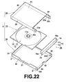
- FIG. 22 is an exploded perspective view of the disk housing case 5 in a closed state.
- Figure 23 is a partial plan view of the disk housing case 5 in an open state.
- the ends of the pair of case halves 20 and 30 toward the viewer are the link ends E (first ends), and the ends away from the viewer are the ends F (second ends) .
- Figures 24A, 24B, 24C, and 24D illustrate the movement of a rotating lid 70 to be described later, and are sectional views taken along line XXIV-XXIV of Figure 23.
- Figure 25 is a partial sectional view taken along line XXV-XXV of Figure 23.
- Figures 26A and 26B are side views of an end wall 74 to be described later, when the rotating lid 70 is in a closed state and an open state, respectively.
- the recording medium disk 2 and indexes 41 and 42 are omitted from the figures as appropriate.
- the third embodiment a configuration was adopted wherein: no side wall was provided at the ends F of either of the case halves 20 and 30; and the opening formed thereby served as the index entry/exit opening 53 for both the front side index 41 and the rear side index 42.
- the wall 18, for partially sealing the space between the disk tray 10 and the rear side index 42, was provided to suppress entry of dust and the like into the disk housing case 4.
- the disk housing case 5 of the present embodiment has no side walls are provided at the link ends E of either of the case halves 20 and 30.
- the rotating lid 70 which is capable of sealing at least a portion of the index exit/entry opening 55 without impeding insertion and removal of the rear side index 42, is provided.
- the rotating lid 70 is pivotally supported at the interior of the front case half 20.
- the rotating lid 70 is provided instead of the wall 18 of the third embodiment, to suppress entry of dust and the like into the disk housing case 5.
- the rotating axis of the rotating lid is coaxial with a rotating axis L, about which the pair of case halves 20 and 30 rotate during opening and closing thereof.
- side walls 23 and 33 are respectively provided at the ends F of the case halves 20 and 30.
- the side wall 23 of the front case half 20 overlaps with the side wall 33 of the rear case half 30, to the exterior thereof. Thereby, the rear case half 30 is fitted into the front case half 20.
- the rotating lid 70 comprises: an upper plate 71, which is arranged between the link arms 22a; a side plate 72, which is formed continuous with the upper plate 71 and substantially perpendicular thereto; and a pair of fan shaped end walls 72, which are provided at both ends of the L-shaped portion 73 formed by the upper plate 71 and the side plate 72.
- the upper plate 71 becomes coplanar with the main body 21 of the front case half 20 when the disk housing case 5 is in a closed state.
- the side plate 72 faces the side wall 33 of the rear case half 30 when the disk housing case 5 is in a closed state.
- the flat portion 14b of the disk tray 10 as illustrated in Figure 15 is not provided, because the rotating lid 70 comprises the upper plate 71.
- the rear side index 42 is of the bent type, comprising: the main index portion 42a; and a sub index portion 42c, to be viewed from the link ends of the pair of case halves 20 and 30.
- the sub index portion 42c is housed along the inner surface of the side plate 72 of the rotating lid 70.
- protrusions 32c are provided on the exterior surfaces of the pair of side walls 34 of the rear case half 30, and protrusions 32d are provided on the interior surfaces thereof.
- the protrusions 32c and 32d are arranged coaxially.
- Apertures 22c, for the protrusions 32c to enter, are provided in each of the pair of link arms 22a of the front case half 20.
- Apertures 74a, for the protrusions 32d to enter, are provided in each of the pair of end walls 74 of the rotating lid 70.
- the front case half 20 is pivotally supported by the rear case half 30 so as to be rotatable about the pair of protrusions 32c.
- the rotating lid 70 is pivotally supported by the rear case half 30 so as to be rotatable about the pair of protrusions 32d.
- the contact opening 52 is provided in the rear case half 30 toward the side of the index entry/exit opening 55.
- the contact opening 52 is provided at the substantial center of the link end E of the rear case half 30.
- the shape of the contact opening 52 is the same as that of the third embodiment.
- the height of the upper plate 71 is set to be lower than the height of the side plate 72.
- engagement means for engaging the rotating lid 70 at its closed position illustrated in Figure 24A, and at its open position illustrated in Figure 24C.
- two engaging protrusions 75 and 76 are provided on the exterior surfaces of the pair of end walls 74 of the rotating lid 70, as illustrated in Figures 26A and 26B.
- engaging grooves 32a with which the engaging protrusions 75 and 76 engage, are provided in the portions of the side walls 32 of the rear case half 30 that face the end walls 74.
- the engaging protrusions 75 and 76 are arranged in a direction parallel to the plane of the side plate 72.
- the engaging grooves 32a are formed as L-shaped grooves. This shape enables the engaging protrusions 75 and 76 to engage the engaging groove 32a in both the closed position illustrated in Figure 26A and the open position illustrated in Figure 26B.
- the L-shape also enables the engaging protrusions 75 and 76 to slide smoothly within the engaging grooves 32a, which are fixed in position.
- the rear side index 42 can be removed from the disk housing case 5, by: contacting the main index portion 42a with a finger or the like, through the contact opening 52 in the rear case half 30; causing the rear side index 42 to slide; and pulling the rear side index 42 through the gap 56.
- the sub index portion 42c is exposed to the exterior of the disk housing case 5 by the rotation of the rotating lid 70. Therefore, removal of the sub index portion 42c is also facilitated.
- Insertion of the rear side index 42 may be performed, by performing the above operations in reverse.
- the disk housing case 5 of the present embodiment is constructed as described above.
- the disk housing case 5 is of a construction, in which: neither the case half 20 nor the case half 30 is provided with a side wall at the link end E thereof; and the opening formed by the lack of side walls being the index entry/exit opening 55, through which the rear side index 42 can be inserted and removed.
- the contact opening 52 for enabling a finger or the like to contact the rear side index 42 to insert and remove the rear side index 42, is provided in the rear case half 30.
- a finger can contact the rear side index 42 through the contact opening 52 to slide the rear side index 42 while the disk tray 10 is fitted in the rear case half 30.
- the rear side index 42 can be inserted and removed through the ends E of the case halves 20 and 30, at which no side wall is provided. Accordingly, insertion and removal of the rear side index 42, which is interposed between the disk tray 10 and the rear case half 30, in which the disk tray 10 is fitted, can be realized without removing the disk tray 10 from the rear case half 30.
- the rotating lid 70 is provided.
- the rotating lid is capable of sealing at least a portion of the index exit/entry opening 55 without impeding insertion and removal of the rear side index 42. Accordingly, entry of dust and the like into the disk housing case 5 can be suppressed, while securing ease in insertion and removal of the rear side index 42.
- the engaging means (the engaging protrusions 75, 76, and the engaging grooves 32e) are provided on the rotating lid 70 and the rear case half 30.
- the engaging means engages the rotating lid 70 at its closed position and its open position. Therefore, the rotating lid 70 is favorably fixed to the case half 30 in either the closed or open state thereof.
- the rear side index 42 can be prevented from protruding outwardly from the rotating lid 70 during normal use, thereby favorably housing the rear side index 42 within the disk housing case 5.
- the gap 56 through which the rear side index 42 is inserted and removed, can be favorably secured during insertion and removal of the rear side index 42. As a result, stable insertion and removal of the rear side index 42 can be realized.
Abstract
Description
- The present invention relates to a disk housing case for housing recording media disks, such as CD's, DVD's, and BD's, and particularly to entry/exit structure of indexes therefor.
- Japanese Unexamined Patent Publication No. 10(1998)-106203 discloses a widely used disk housing case, for housing recording media disks, such as CD's (Compact Discs), DVD's (Digital Versatile Discs), and BD' s (Blu-ray Discs). This disk housing case comprises: a disk tray, for removably holding the recording media disk; and a pair of case halves, which are linked to each other at one of the ends thereof to be openable and closable, for housing the disk tray.
- Generally, in the type of disk housing case having a single disk tray, the disk tray is fitted into a rear case half from the pair of case halves. A front index and a rear index, in the form of cards or booklets, are attached to the front case half and the inner surface of the rear case half.
- When data is recorded onto a recording medium disk, or when recorded data is edited, there are cases in which the content described on the rear index is edited, or the rear index itself is exchanged. The rear index is interposed between the disk tray and the rear case half, into which the disk tray is fitted. Therefore, insertion and removal of the rear index requires removal of the disk tray form the rear case half, causing the insertion and removal procedures to be troublesome.
- In view of these circumstances, Japanese Utility Model No. 3094214 discloses a disk housing case, to which no indexes are attached. In this disk housing case, an index portion, which is formed as a rough surface, is provided on the outer surface of a case half, to enable writing and editing of content on the index portion with a pencil or the like.
- However, the amount of information capable of being recorded by writing and editing of content on the roughened index portion is limited, and the index portion is not aesthetically pleasing.
- The present invention has been developed in view of these circumstances. It is an object of the present invention to provide a disk housing case that enables insertion and removal of an index, which is interposed between a disk tray and a case half into which the disk tray is fitted, without removing the disk tray from the case half.
- The disk housing case of the present invention comprises:
- a disk tray, for removably holding a recording medium disk; and
- a pair of case halves, which are linked at first ends thereof so as to be openable and closable, for housing the disk tray;
- the disk tray being fitted into at least one of the case halves;
- a card type or a booklet type index being interposed between the disk tray and the case half, in which the disk tray is fitted;
- an index entry/exit opening, which opens at least when the index is inserted or removed, being provided at the first ends or the second ends of the pair of case halves; and
- a contact opening, for enabling a finger or an index sliding member to contact the index to insert and remove the index, being provided in the disk tray and/or the case half, in which the disk tray is fitted.
- In the disk housing case of the present invention, it is preferable that:
- a side wall is formed on at least one of the pair of case halves, at the first end and/or the second end thereof; and
- the index entry/exit opening is a slit provided in the side wall.
- In the disk housing case of the present invention, it is preferable that the disk tray comprises: a substantially discoid disk housing recess, where the recording media disk is fitted into and housed; and a flared portion that extends toward the exterior of the disk housing recess;
protrusive ribs, for pressing the index toward the case half, are provided on the flared portion; and
the direction in which the ribs extend is parallel to the insertion/removal direction of the index. - In the disk housing case of the present invention, it is preferable that:
- a stop member, for preventing inadvertent removal of the index, is provided in the case half, into which the disk tray is fitted, toward the side of the index entry/exit opening.
- In the disk housing case of the present invention, it is preferable that:
- there are no side walls at the first and/or second ends of the case halves, the opening formed due to the lack of the side walls serving as the index entry/exit opening; and
- wall portions, for partially sealing the gap between the disk tray and the index, while leaving space for the index to be inserted and removed therethrough, is provided on the disk tray toward the side of the index entry/exit opening.
- In the disk housing case of the present invention, it is preferable that:
- the disk tray comprises: a substantially discoid disk housing recess, where the recording media disk is fitted into and housed; and a flared portion that extends toward the exterior of the disk housing recess;
- the contact opening is provided in the case half, into which the disk tray is fitted, at a portion thereof that faces the flared portion; and
- a support portion, for supporting the index from the side of the disk tray at least during insertion and removal of the index, is provided on the disk tray at a portion thereof that faces the contact opening.
- In the disk housing case of the present invention, it is preferable that:
- the contact opening is provided in the case half, into which the disk tray is fitted; and
- the portion of the index which is exposed through the contact opening is covered with a surface protective layer.
- In the disk housing case of the present invention, it is preferable that:
- the index entry/exit opening is provided in only one of the first ends and the second ends of the pair of case halves; and
- an index guiding portion having a curved surface to regulate the index when it is inserted through the index entry/exit opening, such that the leading end thereof curves along the curved surface to enable visual recognition thereof from the side of the case halves, is provided in the case half, into which the disk tray is fitted and/or the disk tray.
- In the disk housing case of the present invention, it is preferable that:
- there are no side walls at the first and/or second ends of the case halves, the opening formed due to the lack of the side walls serving as the index entry/exit opening; and
- a rotatable lid, which seals at least a portion of the index entry/exit opening without obstructing insertion or removal of the index through the index entry/exit opening, is rotatably supported by one of the pair of case halves.
- An index entry/exit opening is provided at a linked side or at an end opposite the liked side of the pair of case halves in the disk housing case of the present invention. In addition, a contact opening, for enabling a finger or an index sliding member to contact the index to insert and remove the index, is provided in the disk tray and/or the case half, in which the disk tray is fitted.
- Because of this construction, the index can be slid by contacting it with a finger or the like through the contact opening, while the disk tray is mounted in the case half, and the index can be inserted or removed through the index entry/exit opening. Accordingly, insertion and removal of an index, which is interposed between a disk tray and a case half into which the disk tray is fitted, are enabled without removing the disk tray from the case half.
-
- Figure 1 is an exploded perspective view of a disk housing case according to a first embodiment, in a closed state.
- Figures 2A and 2B are perspective views of the disk housing case of Figure 1 in a closed state.
- Figure 3 is a plan view of the disk housing case of Figure 1 in an open state.
- Figure 4 is a bottom view of the disk housing case of Figure 1 in an open state.
- Figure 5A is a front view of the disk housing case of Figure 1.
- Figure 5B is a sectional view taken along line V-V of Figure 3.
- Figure 5C is a magnified partial view of an end F of Figure 5B.
- Figure 6A is a left side view of the disk housing case of Figure 1, and Figure 6B is a right side view of the disk housing case of Figure 1.
- Figure 7 is a perspective view illustrating a design modification of the disk housing case of the first embodiment.
- Figures 8A, 8B, 8C, 8D, 8E, and 8F illustrate examples of design modifications of the disk housing case of the first embodiment.
- Figures 9A and 9B illustrate examples of design modifications of the disk housing case of the first embodiment.
- Figure 10 is an exploded perspective view of a disk housing case according to a second embodiment, in a closed state.
- Figures 11A and 11B are perspective views of the disk housing case of Figure 10 in a closed state, wherein Figure 11A is a view from the front, and Figure 11B is a view from the rear.
- Figure 12 is a perspective view that illustrates a design modification of the disk housing case according to the second embodiment.
- Figures 13A, 13B, and 13C are sectional views of design modifications of the disk housing cases according to the second embodiment.
- Figures 14A and 14B are sectional views of design modifications of the disk housing case according to the second embodiment.
- Figure 15 is an exploded perspective view of a disk housing case according to a third embodiment, in a closed state.
- Figure 16 is a perspective view of the disk housing case of Figure 15 in a closed state.
- Figure 17 is a perspective view of the disk housing case of Figure 15 in an open state.
- Figure 18 is a plan view of the disk housing case of Figure 15 in an open state.
- Figure 19 is a bottom view of the disk housing case of Figure 15 in an open state.
- Figure 20A is a front view of the disk housing case of Figure 15 in an open state.
- Figure 20B is a sectional view taken along line XX-XX of Figure 18.
- Figure 20C is a magnified partial view of an end F of Figure 20B.
- Figure 21A is a left side view of the disk housing case of Figure 15, and Figure 21B is a right side view of the disk housing case.
- Figure 22 is an exploded perspective view of a disk housing case according to a fourth embodiment, in a closed state.
- Figure 23 is a partial plan view of the disk housing case of Figure 22 in an open state.
- Figures 24A, 24B, 24C, and 24D illustrate the movement of a rotating lid, and are sectional views taken along line XXIV-XXIV of Figure 23.
- Figure 25 is a partial sectional view taken along line XXV-XXV of Figure 23.
- Figures 26A and 26B are side views of an end wall, when the rotating lid is in a closed state and an open state, respectively.
- A disk housing case according to a first embodiment of the present invention will be described with reference to Figures 1 through 6B. The disk housing case of the first embodiment is a case for housing a recording media disk, such as CD's (Compact Discs), DVD's (Digital Versatile Discs), andBD's (Blu-ray Discs). The first embodiment is characterized by the entry/exit structure of indexes.
- Figure 1 is an exploded perspective view of a
disk housing case 1 in a closed state. Figures 2A and 2B are perspective views of thedisk housing case 1 in a closed state (a front case half is omitted in Figure 2B). Figure 3 is a plan view of thedisk housing case 1 in an open state. Figure 4 is a bottom view of thedisk housing case 1 in an open state. Figure 5A is a front view of the disk housing case 1 (a rear view is the same as the front view, and therefore is omitted). Figure 5B is a sectional view taken along line V-V of Figure 3. Figure 5C is a magnified partial view of an end F of Figure 5B. Figure 6A is a left side view of thedisk housing case 1, and Figure 6B is a right side view of thedisk housing case 1. Arecording medium disk 2 andindexes - As illustrated in Figures 1, 2A, and 2B, the
disk housing case 1 of the present embodiment comprises: adisk tray 10, for removably holding therecording medium disk 2; afront case half 20; and arear case half 30. Thefront case half 20 and therear case half 30 are openable and closable, and thedisk tray 10 is housed therein. The pair of case halves 20 and 30 are arranged such that they face each other with thedisk tray 10 therebetween, and are linked at the left side ends (first ends) thereof in Figure 1. Thedisk tray 10 is removably fitted into therear case half 30. - The
disk tray 10 and the case halves 20 and 30 that house thedisk tray 10 are substantially rectangular in plan view, are formed of the same or different types of resin, with colors or patterns as desired. However, regarding at least the case halves 20 and 30, it is preferable that they are transparent, considering the need to visual recognize the contents of indexes. - A
front side index 41 is interposed between thefront case half 20 and thedisk tray 10, and arear side index 42 is interposed between therear case half 30 and thedisk tray 10. Theindexes disk housing case 1 of the present embodiment is of a construction in which therear side index 42 is insertable and extractable from the sides of thedisk housing case 1. The details of this construction will be described later. The insertion/removal direction of therear side index 42 is denoted by arrow Y in Figure 1. - The
indexes recording medium disk 2, a photograph, or lines in which the contents of therecording medium disk 2 can be edited, printed thereon. - The
front case half 20 comprises: a plate likemain body 21 that faces thedisk tray 10; and a pair ofside walls 22 that extend in an insertion/removal direction Y of therear side index 42. Theside walls 22 extend beyond themain body 21, and the extended portions arelink arms 22a that link thefront case half 20 with therear case half 30. - The
rear case half 30 comprises: a plate likemain body 31 that faces thedisk tray 10; and a pair ofside walls 32 that extend in the insertion/removal direction Y of therear side index 42.Cutout portions 32a are provided at the central portions of theside walls 32, to enable fingers to engage thedisk tray 10, thereby facilitating removal thereof from therear case half 30. - The areas of the
main bodies side walls 22 of thefront case half 20 are positioned outside theside walls 32 of therear case half 30. That is, the areas of themain bodies rear case half 30 can be fitted within thefront case half 20. -
Protrusions 22b are provided on the inner surfaces of the pair oflink arms 22a that constitute thefront case half 20.Recesses 32b, for the tips of theprotrusions 22b to enter, are provided in the outer surfaces of the pair ofside walls 32 that constitute therear case half 30. The pair of case halves 20 and 30 are linked at the first ends (left side ends in Figure 1) thereof such that they are openable and closable, by thefront case half 20 being pivotally supported on therear case half 30 by the pair ofprotrusions 22b. The first ends will be referred to as "link ends" and denoted with reference letter E. The ends opposite the first end (right side ends in Figure 1, second ends) will be denoted with reference letter F (refer to Figure 2A). - The
disk tray 10 comprises a traymain body 13, constituted by: a substantially discoiddisk housing recess 11, into which therecording medium disk 2 is fitted and housed; and a flaredportion 12 that extends toward the exterior of thedisk housing recess 11. Adisk clamper 11a, for removably holding a central opening portion of therecording medium disk 2, is provided at the central portion of thedisk housing recess 11. - An L-shaped
portion 14, constituted by: aside wall 14a, which extends upward from the surface of the flaredportion 12; and aflat portion 14b, which is continuous with theside wall 14a and parallel to the surface of the flaredportion 12, is provided on the flaredportion 12 toward the side of the link ends of the pair of case halves 20 and 30. Theflat portion 14b is positioned between the pair oflink arms 22a, and becomes coplanar with themain body 21 of thefront case half 20 when the pair of case halves 20 and 30 are in a closed state. As illustrated in Figures 5B and 5C, aside wall 15, which is substantially symmetrical with respect to theside wall 14, is provided on the flaredportion 12 at the end thereof opposite the link ends of the case halves 20 and 30. - Hereinafter, the entry/exit structure of the index, and the manner in which the index is inserted and removed will be described.
- As illustrated in Figure 3, three substantially semicircular engaging
pieces 25, for engaging and holding thefront side index 41, are provided on each of the pair ofside walls 22 of thefront case half 20, parallel to the surface of themain body 21. As illustrated in Figure 1, there is no side wall at the side of the link end E of thefront case half 20, thereby forming an opening. This configuration enables thefront side index 41 to be inserted and removed from the open link end E of thefront case half 20, by sliding theindex 41 between themain body 21 and the engagingpieces 25. An arrow X denotes the insertion/removal direction of thefront side index 41. Aside wall 34 is provided at the link end E of therear case half 30, and recesses 12a, into which the engagingpieces 25 enter, are formed in the flaredportion 12 of thedisk tray 10. - There are no engaging pieces for engaging an index on the
rear case half 30, and therear side index 42 is to be inserted into the gap between themain body 31 of therear case half 30 and thedisk housing recess 11 of thedisk tray 10. There is a space between the flaredportion 12 of thedisk tray 10 and themain body 31 of therear case half 30. Therefore,protrusive ribs 16, for pressing therear side index 42 toward therear case half 30, are provided on the flaredportion 12. As illustrated in Figure 3, fourprotrusive ribs 16 are provided in the vicinity of the corners of the flaredportion 12, close to therecesses 12a. - As illustrated in Figure 5C, each
protrusive rib 16 is a plate-like protrusions having atrapezoidal surface 16a that constricts from the side of thefront case half 20 to the side of therear case half 30. In the present embodiment, the direction that theprotrusive ribs 16 extend is parallel to the insertion/removal direction Y of therear side index 42. - In the present embodiment, a
slit 50, which is an index entry/exit opening through which therear side index 42 is inserted and removed, is provided at the end F, opposite from the link end E of the pair of case halves 20 and 30. - Specifically, as illustrated in Figure 1 and Figure 2, there is no side wall at the end F of the
rear case half 30, thereby creating an opening. Aside wall 23 is provided at the end F of thefront case half 20. Theside wall 23 is formed to be lower than theside walls 22, which extend parallel to the insertion/removal direction Y of therear side index 42. Thereby, theslit 50 is formed between theside wall 23 and themain body 31 of therear case half 30 when the pair of case halves 20 and 30 are in a closed state. The height of theside wall 23 is set such that the height of theslit 50 is greater than the thickness of therear side index 42, while preventing entry of dust and the like into thedisk housing case 1. - In the present embodiment,
contact openings 51, for enabling a finger, preferably a thumb, or an index sliding member, such as a pen, to contact therear side index 42 to insert and remove the index, are provided in thedisk tray 10. - The
contact openings 51 are provided at two locations in thedisk tray 10, toward the side of theslit 50. Both of thecontact openings 51 are formed so as to straddle thedisk housing recess 11 and the flaredportion 12 of thedisk tray 10. - In the present embodiment, the
rear side index 42 is inserted and removed in the following manner. First, the pair of case halves 20 and 30 are opened. Then, the recording media disk is removed. Next, a finger or an index sliding member is caused to contact therear side index 42 through acontact opening 51, to slide therear side index 42 in or out through the slit 50 (index entry/exit opening) provided at the ends F of the pair of case halves 20 and 30. - As illustrated in Figures 5C and 6B,
stoppers 35, for preventing inadvertent removal of therear side index 42, are provided in therear case half 30 toward the end F, at which the index entry/exit opening is provided. Thestoppers 35 are ridges provided at the end of themain body 31 of therear case half 30. Thestoppers 35 are formed at the right and left sides of the central portion of the end F, when viewed from the index entry/exit opening. Reference letters S1 and S2 denote the regions at which thestoppers 35 are formed. Thestoppers 35 are integrally formed with themain body 31 of therear case half 30. - The height H1 of the
stoppers 35 is set such that not insertion and removal of therear side index 42 is not greatly impeded, while inadvertent removal thereof is prevented. Preferably, the height H1 is greater than a thickness H2 of therear side index 42 and less than a distance H3 between the flaredportion 12 of thedisk tray 10 and themain body 31 of therear case half 30. - The
disk housing case 1 of the present embodiment is constructed as described above. - The
disk housing case 1 of the present embodiment is of a construction, in which: theslit 50, which is the index entry/exit opening, is provided in the pair of case halves 20 and 30 at the ends F thereof, which is opposite to the link ends; and thecontact openings 51, for enabling a finger or an index sliding member to contact therear side index 42 to insert and remove the index, are provided in thedisk tray 10. - In this
disk housing case 1 as described above, a finger can contact therear side index 42 through acontact opening 51 to slide therear side index 42 while thedisk tray 10 is fitted in therear case half 30. Thereby, therear side index 42 can be inserted and removed through theslit 50, provided at the ends F of the pair of case halves 20 and 30. Accordingly, insertion and removal of therear side index 42, which is interposed between thedisk tray 10 and therear case half 30, in which thedisk tray 10 is fitted, can be realized without removing thedisk tray 10 from therear case half 30. - Further, the
protrusive ribs 16 are provided on the flaredportion 12 of thedisk tray 12 to press therear side index 42 toward therear case half 30. The direction in which theprotrusive ribs 16 extend is parallel to the insertion/removal direction Y of therear side index 42. This direction is perpendicular to the direction in which protrusive ribs of conventional disk housing cases extend. By this configuration, the width of the portion of theprotrusive ribs 16 that the rear side index passes through is small when viewed from the index entry/exit opening, as illustrated in Figure 6B. Therefore, there is no possibility that sliding motion of therear side index 42 will be prevented by the presence of theprotrusive ribs 16. Therear side index 42 can slide smoothly along the direction that theprotrusive ribs 16 extend. In this manner, smooth insertion and removal of therear side index 42 is realized, because therear side index 42 slides smoothly. - Still further, in the present embodiment, a configuration is adopted wherein the
stoppers 35, for preventing inadvertent removal of therear side index 42, are provided in therear case half 30, toward the end F opposite from the link end thereof. Therefore, there is no possibility that therear side index 42 will be inadvertently removed through theslit 50, improving the handling properties of thedisk housing case 1. - Particularly, in the present embodiment, the
stoppers 35 are not formed across the entire end of themain body 31 of therear case half 30, but are formed on the left and right sides thereof as viewed from the index entry/exit opening and not at the central portion. By this configuration, therear side index 42 is capable of being inserted and removed without riding over thestopper 35 at the central portion. Accordingly, the effect of preventing inadvertent removal of therear side index 42 is sufficiently secured, while not impeding insertion and removal thereof. - In the first embodiment, the
slit 50, which is the index entry/exit opening, is formed by not providing a side wall at the end F of therear case half 30, and by providing theside wall 23, which is shorter than theside walls 22, at the end F of thefront case half 20. However, the present invention is not limited to such a configuration. For example, theside wall 23 may not be provided at the end F of thefront case half 20 and aside wall 33 may be provided at the end F of therear case half 30 having theslit 50 formed therein, as illustrated in Figure 7. - In the first embodiment, two
contact openings 51 are provided in thedisk tray 10 toward the side of the index entry/exit opening such that they straddle thedisk housing recess 11 and the flaredportion 12. By this configuration, both thumbs can contact therear side index 42 through thecontact openings 51. In addition, because the areas of the contact openings are comparatively large, fingers can move within thecontact openings 51, facilitating insertion and removal of therear side index 42. - However, the location, shape, and number of
contact openings 51 are not limited to those of the first embodiment, and may be set as appropriate. Figures 8A, 8B, 8C, 8D, 8E, and 8F illustrate other formation patterns of thecontact openings 51. - Figures 8A, 8B, 8C, and 8F illustrate examples in which the
contact openings 51 are formed only in the flaredportions 12 of thedisk tray 10. In these examples, thecontact openings 51 are not formed in thedisk housing recess 11. Therefore, therear side index 42 can be inserted and removed without removing therecording medium disk 2 from thedisk tray 10. - In the case that the
rear side index 42 is of the bent type, comprising: a main index portion that faces the main surface of the rear case half 30 (the surface of the main body 31) ; and a sub index portion which is viewed from the side of the link ends of the case halves 20 and 30, the example of Figure 8C is preferable. This is because thecontact openings 51 are provided toward the side of the index entry/exit opening and toward the side of the link ends, facilitating insertion of the sub index portion. In the example of Figure 8F, thecontact opening 51 is open toward the index entry/exit opening. Therefore, the edge of therear side index 42 can be directly grasped during insertion and removal. - Figures 8D and 8E illustrate examples in which the contact openings are provided only in the
disk housing recess 11 of thedisk tray 10. In these examples, thecontact openings 51 are not exposed when therecording medium disk 2 is housed in thedisk housing recess 11. Therefore, index preservation properties (anti soil properties, anti corrosionproperties, and the like) are favorable. In addition, thecontact openings 51 are not exposed to users when therecording medium disk 2 is housed in thedisk housing recess 11. Therefore, the outer appearance of thedisk housing case 1 in an open state is the same as that of conventional disk housing cases, which is preferable in terms of aesthetics. - In the example of Figure 8E, in which a
single contact opening 51 is provided in thedisk housing recess 11 toward the side of the index entry/exit opening, sufficient index insertion/removal properties are secured, while suppressing the total area of thecontact opening 51. Therefore, the mechanical strength of thedisk tray 10 is improved. - In addition, marks 60 that indicate the insertion/removal direction Y of the rear side index 42 (for example, arrows or the word "PUSH") may be provided on the
rear side index 42 at the portions corresponding to thecontact openings 51 and/or thedisk tray 10. By this configuration, the insertion/removal direction Y of therear side index 42 can be easily recognized by users. - As will be described in the second embodiment, the contact openings may be provided in the
rear case half 30. In this case, themarks 60 may be provided on therear side index 42 and/or therear case half 30. - The first embodiment is a
disk housing case 1, in which thedisk tray 10 is fitted only in therear case half 30. The present invention is applicable to disk housing cases, in which thedisk tray 10 is fitted in at least one of the pair of case halves 20 and 30. - A
disk housing case 3 according to a second embodiment of the present invention will be described with reference to Figures 10, 11A, and 11B. The basic structure of thedisk housing case 3 is the same as that of thedisk housing case 1 of the first embodiment. Structural elements which are the same as those of the first embodiment will be denoted with the same reference numerals, and detailed descriptions thereof will be omitted. Figure 10 is an exploded perspective view of thedisk housing case 3 in a closed state. Figures 11A and 11B are perspective views of thedisk housing case 3 in a closed state, wherein Figure 11A is a view from the front, and Figure 11B is a view from the rear. - The
disk housing case 3 is configured such that therear side index 42 is insertable and removable through the slit 50 (index entry/exit opening), which is provided at the ends F opposite to the link ends of the pair of case halves 20 and 30, in a manner similar to that of the first embodiment. That is, similar to the first embodiment, there is no side wall at the end F of therear case half 30, thereby creating an opening. In addition, theside wall 23 is provided at the end F of thefront case half 20. Theside wall 23 is formed to be lower than theside walls 22, which extend parallel to the insertion/removal direction Y of therear side index 42. Thereby, theslit 50 is formed between theside wall 23 and themain body 31 of therear case half 30 when the pair of case halves 20 and 30 are in a closed state. - In the first embodiment, the contact openings were provided in the
disk tray 10. In contrast, in the second embodiment, acontact opening 52 is provided in therear case half 30, at a position that faces the flaredportion 12 of the disk tray. Thecontact opening 52 enables a finger or the like to contact therear side index 42. Thecontact opening 52 is shaped as a substantially semicircular cutout at the end of therear case half 30 toward the index entry/exit opening. - In the present embodiment, a portion of the
rear side index 42 is always exposed through thecontact opening 52. Therefore, the portion of therear side index 42 which is exposed through thecontact opening 52 is covered by a surfaceprotective layer 42S, as illustrated in Figure 11B. - The surface
protective layer 42S protects the exposed portion of therear side index 42, to suppress soiling and damage (peeling of printed matter and the like) thereof. Accordingly, it is preferable that the surfaceprotective layer 42S has anti-soiling and anti-abrasion properties. Specific preferred examples include resins, such as polyethylene, polypropylene, polyvinyl chloride, and polystyrene. The surfaceprotective layer 42S may be formed, for example, by: (1) coating theindex 42 with a liquid that contains resins by a dispensing method; (2) attaching a resin film, formed in the shape of the surface protective layer (a semicircle in the illustrated example) onto theindex 42 with an adhesive; or (3) directly attaching a resin film onto theindex 42 by laminating or the like. - The
disk housing case 3 of the present embodiment is constructed as described above. - The
disk housing case 3 of the present embodiment is of a construction, in which: theslit 50, which is the index entry/exit opening, is provided in the pair of case halves 20 and 30 at the ends F thereof, which is opposite to the link ends; and thecontact openings 52, for enabling a finger or the like to contact therear side index 42 to insert and remove the index, are provided in therear case half 30. - In this
disk housing case 3 as described above, a finger can contact therear side index 42 through thecontact opening 52 to slide therear side index 42 while thedisk tray 10 is fitted in therear case half 30. Thereby, therear side index 42 can be inserted and removed through theslit 50, provided at the ends F of the pair of case halves 20 and 30. Accordingly, insertion and removal of therear side index 42, which is interposed between thedisk tray 10 and therear case half 30, in which thedisk tray 10 is fitted, can be realized without removing thedisk tray 10 from therear case half 30. - In the first embodiment, it was necessary for the pair of case halves 20 and 30 to be in an open state to perform insertion and removal of the
rear side index 42. In contrast, insertion and removal of therear side index 42 can be performed with the pair of case halves in either the open or closed states in the present embodiment. - Further, in the
disk housing case 3 of the present embodiment, the portion of therear side index 42, which is exposed through thecontact opening 52, is covered by the surfaceprotective layer 42S. Therefore, soiling and damage to the exposed portion of therear side index 42 is suppressed, and the exposed portion is favorably protected. - In the present embodiment, the region at which the surface
protective layer 42S is formed matches the region at which thecontact opening 52 is open. Similar advantageous effects can be obtained as long as at least the portion of therear side index 42, which is exposed through thecontact opening 52, is covered by the surfaceprotective layer 42S. However, it is preferable that the surfaceprotective layer 42S is formed in the minimum required region, from the viewpoint of costs and the degree of freedom in editing the contents of therear side index 42. That is, it is preferable that the surfaceprotective layer 42S is formed only at the portion of therear side index 42 which is exposed through thecontact opening 52 and the vicinity thereof, that may be exposed due to positional displacement of therear side index 42 within therear case half 30. - In the second embodiment, the
slit 50, which is the index entry/exit opening, is formed by not providing a side wall at the end F of therear case half 30, and by providing theside wall 23, which is shorter than theside walls 22, at the end F of thefront case half 20, similar to the configuration of the first embodiment. However, the present invention is not limited to such a configuration. For example, theside wall 23 may not be provided at the end F of thefront case half 20 and aside wall 33 may be provided at the end F of therear case half 30 having theslit 50 formed therein, as illustrated in Figure 7. - As the second embodiment, a configuration has been described, in which a
single contact opening 52 is formed as a substantially semicircular cutout at the end of therear case half 30 toward the index entry/exit opening. The location, shape, and number of thecontact opening 52 are not limited to those of the second embodiment, and can be set as appropriate. For example, as illustrated in Figure 12, twocontact openings 52 may be provided in therear case half 30 at portions that face the flaredportion 12 of thedisk tray 10. Further, thecontact openings 51 as described in the first embodiment may also be provided in thedisk tray 10, in addition to thecontact openings 52 in therear case half 30. - In the second embodiment, a case has been described in which the rear side index is of a non-bent type. However, the
rear side index 42 may be of the bent type, comprising: a main index portion that faces the main surface of the rear case half 30 (the surface of the main body 31); and a sub index portion which is viewed from the side opposite that of the link ends of the case halves 20 and 30. - Design modifications, in the case that the
rear side index 42 comprises thesub index portion 42b, will be described with reference to Figures 13A, 13B, and 13C. Figures 13A, 13B, and 13C are sectional views of disk housing cases in closed states, taken along the thickness directions thereof. - As illustrated in Figure 13A, in the case that the
rear side index 42 comprises asub index portion 42b, thesub index portion 42b may be pulled out of theslit 50, then bent 90° such that it is arranged along theouter surface 23a of theside wall 23. In this case, thesub index portion 42b is not housed within the disk housing case. Therefore, therear side index 42 can be inserted and removed while the pair of case halves are in a closed state, as in the second embodiment. - As illustrated in Figure 13B, the
end 21a of themain body 21 of thefront case half 20 and theend 31a of themain body 31 of therear case half 30 may be caused to protrude slightly beyond theouter surface 23a of theside wall 23. This configuration is preferable, because thesub index 42b can be housed within the space formed by the protrusive ends 21a and 31a, thereby protecting thesub index portion 42b. - Further, as illustrated in Figure 13C, it is preferable that a
slit 57 is formed in theside wall 23 toward the side of themain body 21. In this case, the leading end of thesub index portion 42b is bent 90° and inserted into theslit 57. This configuration favorably fixes the leading end of thesub index portion 42b, and suppresses separation thereof from theside wall 23. - A configuration may be adopted, wherein the
sub index portion 42b is arranged along the inner surface of theside wall 23 of thefront case half 20. In this case, thesub index portion 42b may be pulled out of theslit 50 with the pair of case halves 20 and 30 in an open state, prior to inserting or removing therear side index 42. - The
rear side index 42 may alternatively be of a bent type, comprising: themain index portion 42a; and asub index portion 42c which is arranged to face theside wall 34 of therear case half 30, to be viewed from the link ends of the pair of case halves 20 and 30. - Design modifications, in the case that the
rear side index 42 comprises thesub index portion 42c, will be described with reference to Figures 14A and 14B. Figures 14A and 14B are sectional views of a disk housing case in a closed state, taken along the thickness directions thereof. - As illustrated in Figures 14A and 14B, in the case that the
rear side index 42 comprises thesub index portion 42c,guide ribs 19, each having acurved surface 19a, may provided on the inner surface of theflat portion 14b of thedisk tray 10.Guide ribs 37, each having acurved surface 37a, may be provided at the corner of themain body 31 and theside wall 34 of therear case half 30. Aplurality of sets of theguide ribs 19 and theguide ribs 37 may be provided along the direction parallel to the surface of theside wall 34. Thecurved surfaces guide ribs index insertion space 58 is formed between thecurved surfaces 19a and thecurved surfaces 37a. Theguide ribs sub index portion 42c, which is the leading end of therear side index 42 inserted through the slit 50 (index entry/exit opening). - Insertion and removal of the
sub index portion 42c is facilitated by the provision of theguide ribs sub index portion 42c to be curved during insertion thereof. A configuration may be adopted wherein only one of theguide ribs 19 and theguide ribs 37 are provided. In addition, the index guide is not limited to being ribs. - The design modifications illustrated in Figures 13A, 13B, 13C, 14A, and 14B are also applicable to the
disk housing case 1 of the first embodiment. - A
disk housing case 4 according to a third embodiment of the present invention will be described with reference to Figures 15 through 21B. The basic structure of thedisk housing case 4 is the same as that of thedisk housing case 3 of the second embodiment. Structural elements which are the same as those of the second embodiment will be denoted with the same reference numerals, and detailed descriptions thereof will be omitted. Figure 15 is an exploded perspective view of thedisk housing case 4 in a closed state. Figure 16 is a perspective view of thedisk housing case 4 in a closed state. Figure 17 is a perspective view of thedisk housing case 4 in an open state. Figure 18 is a plan view of thedisk housing case 4 in an open state. Figure 19 is a bottom view of thedisk housing case 4 in an open state. Figure 20A is a front view of thedisk housing case 4 in an open state (a rear view is the same as the front view, and therefore is omitted). Figure 20B is a sectional view taken along line XX-XX of Figure 18. Figure 20C is a magnified partial view of the end F of Figure 20B. Figure 21A is a left side view of thedisk housing case 4, and Figure 21B is a right side view of thedisk housing case 4. Therecording medium disk 2 andindexes - The first and second embodiments were configured such that one of the case halves 20 and 30 had a side wall at the end F thereof, and the
slit 50 was provided in the side wall. In contrast, in thedisk housing case 4 of the present embodiment, neithercase half 20 nor 30 has a side wall at the end F thereof, as illustrated in Figures 15 and 17. The opening formed by the lack of side walls constitutes an index entry/exit opening 53, through which thefront side index 41 and therear side index 42 can be inserted and removed. - Neither of the ends F of the pair of case halves 20 and 30 toward the side of the index entry/exit opening has a side wall, and are open. Therefore, in the present embodiment, a
wall 18, for partially sealing the gap between the flaredportion 12 and therear side index 42, is provided at the end F of thedisk tray 10. Thewall 18 serves to prevent dust and the like from entering thedisk housing case 4. - As illustrated in Figures 20B and 20C, the
wall 18 of the present embodiment is constituted by: afirst side wall 18a that extends upward toward thefront case half 20 from the flaredportion 12 of thedisk tray 10; and asecond side wall 18b, which is bent back from thefirst side wall 18a toward therear case half 30. Thefirst side wall 18a is substantially symmetrical with theside wall 14a at the link end E of thedisk tray 10. Thesecond side wall 18b is greater in height than thefirst side wall 18a, and extends to the vicinity of themain body 31 of therear case half 30. - As illustrated in Figures 20B, 20C, and 21B, the lower edge of the wall 18 (the lower edge of the
second side wall 18b) is set at a position that leaves agap 54 between thewall 18 and therear case half 30, through which therear side index 42 can be inserted and removed. The details will be described later, butprotrusive stoppers 36 are provided at the end of therear case half 30. Therefore, the distance between thesecond side wall 18b and thestoppers 36 is set to be greater than the thickness of therear side index 42, to ensure that therear side index 42 can be inserted and removed through thegap 54. - As illustrated in Figure 16, it is not necessary to leave a gap, for the front side index to be inserted and removed through, between the upper end of the wall 18 (the bent portion) and the
front case half 20. This is because when the pair of case halves 20 and 30 are in an open state, thefront case half 20 and thewall 18 of thedisk tray 10 are widely separated, and sufficient space for inserting and removing thefront side index 41 appears automatically. A configuration, in which the upper end of thewall 18 abuts themain body 21 of the front case half when the case halves 20 and 30 are in a closed state, is preferable from the viewpoint of preventing dust and the like from entering thedisk housing case 4. - In the present embodiment, a
contact opening 52 is provided in therear case half 30, at a position that faces the flaredportion 12 of the disk tray in a manner similar to that of the second embodiment, as illustrated in Figures 15 and 19. Thecontact opening 52 enables a finger or the like to contact therear side index 42. Thecontact opening 52 is shaped as a substantially semicircular cutout at the end of therear case half 30 toward the index entry/exit opening. - Further, a
support portion 17, for supporting therear side index 42 during insertion and removal thereof, is provided on thedisk tray 10 at a portion that faces thecontact opening 52. Thesupport portion 17 is formed as a rectangular embossed recess, and the depth of the recess is set such that the lower surface thereof approaches therear side index 42. - In the present embodiment, the
front side index 41 is inserted and removed by opening the pair of case halves 20 and 30 to separate thefront case half 10 and thewall 18 of thedisk tray 10. Then, the front side index is caused to slide through the end F, at which there are no side walls. - The
rear side index 42 is inserted and removed by causing a finger or the like to contact therear side index 42 through thecontact opening 52 provided in therear case half 30, while thedisk tray 10 is fitted therein. Then, therear side index 42 is caused to slide through thegap 54. Therear side index 42 can be inserted or removed with the pair of case halves in either an open state or a closed state. - In the present embodiment, both the
front side index 41 and therear side index 42 can be inserted and removed at the end F. Therefore,stoppers indexes main bodies - The
stoppers 26 are formed over comparatively wide ranges to the left and right sides of a central portion of themain body 21, when viewed from the side of the index entry/exit opening. Thestoppers 26 are provided toward the interior of the end F of thefront side case 20, so as to not contact thewall 18 of thedisk tray 10. Thestoppers 36 are provided as small protrusions adjacent to thecontact opening 52 at the end F of the rear case half. The heights of thestoppers indexes stoppers - The
disk housing case 4 of the present embodiment is constructed as described above. - The
disk housing case 4 of the present embodiment is of a construction, in which neither of the case halves 20 and 30 has a side wall at their ends F opposite their link ends. The openings formed thereby constitute the index entry/exit opening 53. In addition, thecontact opening 52, for enabling a finger or the like to contact therear side index 42 to insert and remove therear side index 42, is provided in therear case half 30. In thisdisk housing case 4 as described above, a finger can contact therear side index 42 through thecontact opening 52 to slide therear side index 42 while thedisk tray 10 is fitted in therear case half 30. Thereby, therear side index 42 can be inserted and removed through the ends F of the case halves 20 and 30, at which no side wall is provided. Accordingly, insertion and removal of therear side index 42, which is interposed between thedisk tray 10 and therear case half 30, in which thedisk tray 10 is fitted, can be realized without removing thedisk tray 10 from therear case half 30. - In the present embodiment, neither of the pair of case halves 20 and 30 has a side wall at their ends F opposite their link ends. Therefore, the
front side index 41 can also be inserted and removed through the opening formed by the lack of side walls at the end F, as described above. In the case that thefront side index 41 is inserted or removed at the link end E, it is necessary to feed thefront side index 41 through a gap at the link portion between the case halves 20 and 30. In contrast, the present embodiment enables insertion and removal of theindexes front side index 41 is facilitated as well. - In this manner, the present embodiment enables insertion and removal of the
front side index 41 at the end F as well, which is preferable. However, there is no side wall at the link end E of thefront case half 20, therefore thefront side index 41 can also be inserted and removed at the link end E. - Further, the present embodiment provides the
wall 18 that partially seals the space between thedisk tray 10 and therear side index 42, while leaving thegap 54, through which therear side index 42 can be inserted and removed. Accordingly, entry of dust and the like into thedisk housing case 4 can be suppressed, while securing ease in insertion and removal of both thefront side index 41 and the rear side index, which is interposed between thedisk tray 10 and therear case half 30. - In the case that the
contact opening 52 is simply provided in the portion of therear case half 30 that faces the flaredportion 12, the surface of therear side index 42 opposite the surface to be contacted floats away from thedisk tray 10. In other words, therear side index 42 is not supported from behind, when viewed from the side of thecontact opening 52, which may destabilize the sliding motion thereof. However, the present embodiment is provided with thesupport portion 17 on the disk tray at the portion thereof that faces thecontact opening 52. Therefore, therear side index 42 is supported from behind by thesupport portion 17, to stabilize the sliding motion of therear side index 42 and to enable smooth insertion and removal thereof. - A case in which the
side wall 18, constituted by: thefirst side wall 18a that extends upward toward thefront case half 20 from the flaredportion 12 of thedisk tray 10; and thesecond side wall 18b, which is bent back from thefirst side wall 18a toward therear case half 30, is provided on thedisk tray 10 has been described as the third embodiment. The present invention is not limited to the construction described above. Thewall 18 may be of any construction, as long as it partially seals the space between thedisk tray 10 and therear side index 42, while leaving thegap 54 to enable insertion and removal of therear side index 42 therethrough. The number and shapes of the side walls that constitute thewall 18 may be set as appropriate. For example, thewall 18 may be constituted by: a first side wall that extends toward therear case half 30 from the traymain body 13; and a second side wall, which is bent back from the first side wall to extend toward the front case half 20 (a bending structure reverse from that of the third embodiment). - The location, shape, and number of the
contact opening 52. provided in the rear case half 30are not limited to those of the second embodiment, and can be set as appropriate. Contact openings may be provided in thedisk tray 10, as in the first embodiment. Alternatively, the contact openings may be provided in both therear case half 30 and thedisk tray 10. - A
disk housing case 5 according to a fourth embodiment of the present invention will be described with reference to Figures 22 through 26B. The basic structure of thedisk housing case 5 is the same as that of thedisk housing case 4 of the third embodiment. Structural elements which are the same as those of the first embodiment will be denoted with the same reference numerals, and detailed descriptions thereof will be omitted.
Figure 22 is an exploded perspective view of thedisk housing case 5 in a closed state. Figure 23 is a partial plan view of thedisk housing case 5 in an open state. In Figure 22, the ends of the pair of case halves 20 and 30 toward the viewer are the link ends E (first ends), and the ends away from the viewer are the ends F (second ends) . Figures 24A, 24B, 24C, and 24D illustrate the movement of arotating lid 70 to be described later, and are sectional views taken along line XXIV-XXIV of Figure 23. Figure 25 is a partial sectional view taken along line XXV-XXV of Figure 23. Figures 26A and 26B are side views of anend wall 74 to be described later, when the rotatinglid 70 is in a closed state and an open state, respectively. Therecording medium disk 2 andindexes - In the third embodiment, a configuration was adopted wherein: no side wall was provided at the ends F of either of the case halves 20 and 30; and the opening formed thereby served as the index entry/
exit opening 53 for both thefront side index 41 and therear side index 42. In addition, in the third embodiment, thewall 18, for partially sealing the space between thedisk tray 10 and therear side index 42, was provided to suppress entry of dust and the like into thedisk housing case 4. - In contrast, in the
disk housing case 5 of the present embodiment has no side walls are provided at the link ends E of either of the case halves 20 and 30. The opening formed thereby constitutes an index exit/entry opening 55, through which therear side index 42 is inserted and removed. In addition, the rotatinglid 70, which is capable of sealing at least a portion of the index exit/entry opening 55 without impeding insertion and removal of therear side index 42, is provided. The rotatinglid 70 is pivotally supported at the interior of thefront case half 20. The rotatinglid 70 is provided instead of thewall 18 of the third embodiment, to suppress entry of dust and the like into thedisk housing case 5. In the present embodiment, the rotating axis of the rotating lid is coaxial with a rotating axis L, about which the pair of case halves 20 and 30 rotate during opening and closing thereof. - In the present embodiment,
side walls side wall 23 of thefront case half 20 overlaps with theside wall 33 of therear case half 30, to the exterior thereof. Thereby, therear case half 30 is fitted into thefront case half 20. - The rotating
lid 70 comprises: anupper plate 71, which is arranged between thelink arms 22a; aside plate 72, which is formed continuous with theupper plate 71 and substantially perpendicular thereto; and a pair of fan shapedend walls 72, which are provided at both ends of the L-shapedportion 73 formed by theupper plate 71 and theside plate 72. Theupper plate 71 becomes coplanar with themain body 21 of thefront case half 20 when thedisk housing case 5 is in a closed state. Theside plate 72 faces theside wall 33 of therear case half 30 when thedisk housing case 5 is in a closed state. In the present embodiment, theflat portion 14b of thedisk tray 10 as illustrated in Figure 15 is not provided, because therotating lid 70 comprises theupper plate 71. - As illustrated in Figures 24A, 24B, 24C, and 24D, the
rear side index 42 is of the bent type, comprising: themain index portion 42a; and asub index portion 42c, to be viewed from the link ends of the pair of case halves 20 and 30. Thesub index portion 42c is housed along the inner surface of theside plate 72 of therotating lid 70. - When the pair of case halves 20 and 30 are in a closed state, the pair of
end walls 74 overlap with thepair side walls 34 of the rear case half, toward the interiors thereof, thereby fitting therotating lid 70 within therear case half 30. That is, as illustrated in Figure 25, when the pair of case halves 20 and 30 are in a closed state, therear case half 30 is fitted within thefront case half 20, and therotating lid 70 is fitted within therear case half 30. - In the present embodiment,
protrusions 32c are provided on the exterior surfaces of the pair ofside walls 34 of therear case half 30, andprotrusions 32d are provided on the interior surfaces thereof. Theprotrusions Apertures 22c, for theprotrusions 32c to enter, are provided in each of the pair oflink arms 22a of thefront case half 20.Apertures 74a, for theprotrusions 32d to enter, are provided in each of the pair ofend walls 74 of therotating lid 70. Thefront case half 20 is pivotally supported by therear case half 30 so as to be rotatable about the pair ofprotrusions 32c. The rotatinglid 70 is pivotally supported by therear case half 30 so as to be rotatable about the pair ofprotrusions 32d. - In the present embodiment, the
contact opening 52 is provided in therear case half 30 toward the side of the index entry/exit opening 55. Thecontact opening 52 is provided at the substantial center of the link end E of therear case half 30. The shape of thecontact opening 52 is the same as that of the third embodiment. - Positional changes of the
rotating lid 70 and the method by which therear side index 42 is inserted and removed will be described with reference to Figures 24A, 24B, 24C, and 24D. - As illustrated in Figure 24A, when the rotating
lid 70 is in a closed state, theupper plate 71 is coplanar with themain body 21 of thefront case half 20, and theside plate 72 is at a position at which it faces theside wall 33 of therear case half 30. In this closed state, thesub index portion 42c of therear side index 42 is housed toward the interior of theside plate 72. - When the
rotating lid 70 is rotated counterclockwise, as illustrated in Figure 24B to reach its open state, as illustrated in Figure 24C, theside plate 72 assumes the positions previously assumed by theupper plate 71 in the closed state. At this time, theupper plate 71 moves to a position at which it faces theside wall 33 of therear case half 30. In the open state, theupper plate 71 moves toward the interior of thesub index portion 42c of therear side index 42, to expose thesub index portion 42c. - In the present embodiment, as illustrated in Figures 24C and 24D, the height of the
upper plate 71 is set to be lower than the height of theside plate 72. When therotating lid 70 is in an open state, agap 56, through which therear side index 42 can be inserted and removed, is formed between therotating lid 70 and themain body 31 of therear case half 30. - In the present embodiment, engagement means, for engaging the rotating
lid 70 at its closed position illustrated in Figure 24A, and at its open position illustrated in Figure 24C, are provided. Specifically, two engagingprotrusions end walls 74 of therotating lid 70, as illustrated in Figures 26A and 26B. In addition, engaginggrooves 32a, with which the engagingprotrusions side walls 32 of therear case half 30 that face theend walls 74. - The engaging
protrusions side plate 72. The engaginggrooves 32a are formed as L-shaped grooves. This shape enables the engagingprotrusions groove 32a in both the closed position illustrated in Figure 26A and the open position illustrated in Figure 26B. The L-shape also enables the engagingprotrusions grooves 32a, which are fixed in position. - As illustrated in Figure 24D, the
rear side index 42 can be removed from thedisk housing case 5, by: contacting themain index portion 42a with a finger or the like, through thecontact opening 52 in therear case half 30; causing therear side index 42 to slide; and pulling therear side index 42 through thegap 56. In the present embodiment, thesub index portion 42c is exposed to the exterior of thedisk housing case 5 by the rotation of therotating lid 70. Therefore, removal of thesub index portion 42c is also facilitated. - Insertion of the
rear side index 42 may be performed, by performing the above operations in reverse. - The
disk housing case 5 of the present embodiment is constructed as described above. Thedisk housing case 5 is of a construction, in which: neither thecase half 20 nor thecase half 30 is provided with a side wall at the link end E thereof; and the opening formed by the lack of side walls being the index entry/exit opening 55, through which therear side index 42 can be inserted and removed. In addition, thecontact opening 52, for enabling a finger or the like to contact therear side index 42 to insert and remove therear side index 42, is provided in therear case half 30. - In this
disk housing case 5 as described above, a finger can contact therear side index 42 through thecontact opening 52 to slide therear side index 42 while thedisk tray 10 is fitted in therear case half 30. Thereby, therear side index 42 can be inserted and removed through the ends E of the case halves 20 and 30, at which no side wall is provided. Accordingly, insertion and removal of therear side index 42, which is interposed between thedisk tray 10 and therear case half 30, in which thedisk tray 10 is fitted, can be realized without removing thedisk tray 10 from therear case half 30. - Further, in the present embodiment, the rotating
lid 70 is provided. The rotating lid is capable of sealing at least a portion of the index exit/entry opening 55 without impeding insertion and removal of therear side index 42. Accordingly, entry of dust and the like into thedisk housing case 5 can be suppressed, while securing ease in insertion and removal of therear side index 42. - In addition, the engaging means (the engaging
protrusions engaging grooves 32e) are provided on therotating lid 70 and therear case half 30. The engaging means engages therotating lid 70 at its closed position and its open position. Therefore, the rotatinglid 70 is favorably fixed to thecase half 30 in either the closed or open state thereof. By this configuration, therear side index 42 can be prevented from protruding outwardly from the rotatinglid 70 during normal use, thereby favorably housing therear side index 42 within thedisk housing case 5. In addition, thegap 56, through which therear side index 42 is inserted and removed, can be favorably secured during insertion and removal of therear side index 42. As a result, stable insertion and removal of therear side index 42 can be realized.
Claims (17)
- A disk housing case, comprising:a disk tray, for removably holding a recording medium disk; anda pair of case halves, which are linked at first ends thereof so as to be openable and closable, for housing the disk tray;the disk tray being fitted into at least one of the case halves;a card type or a booklet type index being interposed between the disk tray and the case half, in which the disk tray is fitted;an index entry/exit opening, which opens at least when the index is inserted or removed, being provided at the first ends or the second ends of the pair of case halves; anda contact opening, for enabling a finger or an index sliding member to contact the index to insert and remove the index, being provided in the disk tray and/or the case half, in which the disk tray is fitted.
- A disk housing case as defined in Claim 1, wherein:a side wall is formed on at least one of the pair of case halves, at the first end and/or the second end thereof; andthe index entry/exit opening is a slit provided in the side wall.
- A disk housing case as defined in Claim 2, wherein:the index is a folded index, constituted by a main index portion that faces the main surface of the case half and a sub index portion that faces the side wall; andthe sub index portion is pulled out from the slit to be arranged along the outer surface of the side wall.
- A disk housing case as defined in Claim 1, wherein:the contact opening is provided in the disk tray;the disk tray comprises: a substantially discoid disk housing recess, where the recording media disk is fitted into and housed; and a flared portion that extends toward the exterior of the disk housing recess; andthe contact opening is provided so as to straddle the disk housing recess and the flared portion.
- A disk housing case as defined in Claim 1, wherein:the contact opening is provided in the disk tray;the disk tray comprises: a substantially discoid disk housing recess, where the recording media disk is fitted into and housed; and a flared portion that extends toward the exterior of the disk housing recess; andthe contact opening is provided only in the flared portion.
- A disk housing case as defined in Claim 1, wherein:the contact opening is provided in the disk tray;the disk tray comprises: a substantially discoid disk housing recess, where the recording media disk is fitted into and housed; andthe contact opening is provided only in the disk housing recess.
- A disk housing case as defined in Claim 1, wherein:the disk tray comprises: a substantially discoid disk housing recess, where the recording media disk is fitted into and housed; and a flared portion that extends toward the exterior of the disk housing recess;protrusive ribs, for pressing the index toward the case half, are provided on the flared portion; andthe direction in which the ribs extend is parallel to the insertion/removal direction of the index.
- A disk housing case as defined in Claim 1, wherein:a stop member, for preventing inadvertent removal of the index, is provided in the case half, into which the disk tray is fitted, toward the side of the index entry/exit opening.
- A disk housing case as defined in Claim 1, wherein:there are no side walls at the first and/or second ends of the case halves, the opening formed due to the lack of the side walls serving as the index entry/exit opening; andwall portions, for partially sealing the gap between the disk tray and the index, while leaving space for the index to be inserted and removed therethrough, is provided on the disk tray toward the side of the index entry/exit opening.
- A disk housing case as defined in Claim 9, wherein:the disk tray comprises a tray main body, constituted by: a substantially discoid disk housing recess, where the recording media disk is fitted into and housed; and a flared portion that extends toward the exterior of the disk housing recess; andthe wall portions comprise: a first side wall that extends from the tray main body toward one of the sides of the case halves; and a second side wall, which is bent back from the first side wall toward the other side of the case halves.
- A disk housing case as defined in Claim 1, wherein:the disk tray comprises: a substantially discoid disk housing recess, where the recording media disk is fitted into and housed; and a flared portion that extends toward the exterior of the disk housing recess;the contact opening is provided in the case half, into which the disk tray is fitted, at a portion thereof that faces the flared portion; anda support portion, for supporting the index from the side of the disk tray at least during insertion and removal of the index, is provided on the disk tray at a portion thereof that faces the contact opening.
- A disk housing case as defined in Claim 1, wherein:the contact opening is provided in the case half, into which the disk tray is fitted; andthe portion of the index which is exposed through the contact opening is covered with a surface protective layer.
- A disk housing case as defined in Claim 1, further comprising:marks indicating the insertion/removal direction of the index, provided on at least one of the case half, into which the disk tray is fitted, the disk tray, and the index.
- A disk housing case as defined in Claim 1, wherein:the index entry/exit opening is provided in only one of the first ends and the second ends of the pair of case halves; andan index guiding portion having a curved surface to regulate the index when it is inserted through the index entry/exit opening, such that the leading end thereof curves along the curved surface to enable visual recognition thereof from the side of the case halves, is provided in the case half, into which the disk tray is fitted and/or the disk tray.
- A disk housing as defined in Claim 1, wherein:there are no side walls at the first and/or second ends of the case halves, the opening formed due to the lack of the side walls serving as the index entry/exit opening; anda rotatable lid, which seals at least a portion of the index entry/exit opening without obstructing insertion or removal of the index through the index entry/exit opening, is rotatably supported by one of the pair of case halves.
- A disk housing case as defined in Claim 15, further comprising:engaging means, for engaging the rotatable lid at its closed position and at its open position, provided on the rotatable lid and the pair of case halves.
- A disk housing case as defined in Claim 15, wherein:the pair of case halves are linked such that one of the case halves is rotatable with respect to the other;the index entry/exit opening and the rotatable lid are provided at the first ends of the case halves; andthe rotating axis of the case halves with respect to each other and the rotating axis of the rotatable lid are coaxial.
Applications Claiming Priority (8)
| Application Number | Priority Date | Filing Date | Title |
|---|---|---|---|
| JP2004212924 | 2004-07-21 | ||
| JP2005026922 | 2005-02-02 | ||
| JP2005026920 | 2005-02-02 | ||
| JP2005026919 | 2005-02-02 | ||
| JP2005026918 | 2005-02-02 | ||
| JP2005026921 | 2005-02-02 | ||
| JP2005026917 | 2005-02-02 | ||
| JP2005202472A JP2006240737A (en) | 2004-07-21 | 2005-07-12 | Disc storage case |
Publications (2)
| Publication Number | Publication Date |
|---|---|
| EP1619686A2 true EP1619686A2 (en) | 2006-01-25 |
| EP1619686A3 EP1619686A3 (en) | 2009-06-17 |
Family
ID=35415125
Family Applications (1)
| Application Number | Title | Priority Date | Filing Date |
|---|---|---|---|
| EP05015783A Withdrawn EP1619686A3 (en) | 2004-07-21 | 2005-07-20 | Disk housing case |
Country Status (4)
| Country | Link |
|---|---|
| US (1) | US7353942B2 (en) |
| EP (1) | EP1619686A3 (en) |
| JP (1) | JP2006240737A (en) |
| TW (1) | TW200607724A (en) |
Families Citing this family (2)
| Publication number | Priority date | Publication date | Assignee | Title |
|---|---|---|---|---|
| JP4167239B2 (en) * | 2005-03-15 | 2008-10-15 | 富士フイルム株式会社 | Disc storage case |
| JP6730015B2 (en) * | 2015-10-19 | 2020-07-29 | 株式会社ナベル | Label loading device |
Citations (2)
| Publication number | Priority date | Publication date | Assignee | Title |
|---|---|---|---|---|
| US5878879A (en) * | 1998-03-13 | 1999-03-09 | Liao; Chung Kuang | Cassette holder having easily removable insert |
| US5944180A (en) * | 1996-01-11 | 1999-08-31 | Koh; Lawrence Robert | Self-ejecting compact disc case |
Family Cites Families (9)
| Publication number | Priority date | Publication date | Assignee | Title |
|---|---|---|---|---|
| US5341924A (en) * | 1985-07-18 | 1994-08-30 | Morrone James V | Media storage apparatus |
| JPH0713700Y2 (en) | 1990-01-11 | 1995-04-05 | 株式会社日立ホームテック | Electric Anka |
| GB2261210B (en) * | 1991-11-12 | 1993-11-17 | King Yeung Choi | Holder for compact discs or the like |
| US5495940A (en) * | 1992-04-16 | 1996-03-05 | Sony Corporation | Storage container for mini-disk cartridges |
| US5388713A (en) * | 1993-04-14 | 1995-02-14 | Taniyama; Yoshihiko | Storage container |
| KR19980702176A (en) * | 1995-12-15 | 1998-07-15 | 이데이 노부유키 | Storage case for disc cartridge |
| EP0825607B1 (en) * | 1996-08-23 | 2003-11-26 | Fuji Photo Film Co., Ltd. | Disk cartridge storage case with index card |
| JP3692189B2 (en) | 1996-09-30 | 2005-09-07 | 北野エンジニアリング株式会社 | Disc case |
| ATE300783T1 (en) * | 2003-05-23 | 2005-08-15 | Gundlach Berlin Display & Verp | PACKAGING FOR A DISK-SHAPED RECORDING MEDIUM AND METHOD FOR MAKING SUCH A PACKAGING |
-
2005
- 2005-07-12 JP JP2005202472A patent/JP2006240737A/en not_active Withdrawn
- 2005-07-20 TW TW094124450A patent/TW200607724A/en unknown
- 2005-07-20 EP EP05015783A patent/EP1619686A3/en not_active Withdrawn
- 2005-07-20 US US11/184,998 patent/US7353942B2/en not_active Expired - Fee Related
Patent Citations (2)
| Publication number | Priority date | Publication date | Assignee | Title |
|---|---|---|---|---|
| US5944180A (en) * | 1996-01-11 | 1999-08-31 | Koh; Lawrence Robert | Self-ejecting compact disc case |
| US5878879A (en) * | 1998-03-13 | 1999-03-09 | Liao; Chung Kuang | Cassette holder having easily removable insert |
Also Published As
| Publication number | Publication date |
|---|---|
| JP2006240737A (en) | 2006-09-14 |
| TW200607724A (en) | 2006-03-01 |
| US7353942B2 (en) | 2008-04-08 |
| EP1619686A3 (en) | 2009-06-17 |
| US20060016702A1 (en) | 2006-01-26 |
Similar Documents
| Publication | Publication Date | Title |
|---|---|---|
| US4771883A (en) | Article for storing digital laser disc devices | |
| AU615981B2 (en) | Article for storing optically readable and recordable disc devices | |
| US5513749A (en) | Storage case for multiple compact discs | |
| US5620271A (en) | Three ring binder page for holding compact discs | |
| US6942092B1 (en) | Sleeve for digital media disk | |
| US5477961A (en) | Storage container for digital media and associated materials | |
| US7353942B2 (en) | Disk housing case with index and contact opening therefor | |
| US20080017536A1 (en) | Slide and pivot media storage and display container | |
| EP0493845B1 (en) | Holder for a rectangular cassette | |
| US5735396A (en) | Compact disc storage container | |
| WO1997022539A1 (en) | Housing case for a disk cartridge | |
| US20070012582A1 (en) | Disk protective enclosure | |
| US20020157973A1 (en) | Container for circular disk-shaped objects | |
| EP1834897B1 (en) | Disk case | |
| US20060151343A1 (en) | Media storage disk case | |
| US7350641B2 (en) | Blank for manufacture of a case, a method of forming a case, and the case | |
| US6000537A (en) | Housing with readable side walls for a disc-shaped information carrier | |
| EP1225586B1 (en) | Storage container for recording media | |
| JPH0523511Y2 (en) | ||
| US20040089567A1 (en) | Enclosure for an optical disc, in particular, a cd enclosure | |
| JP3541533B2 (en) | Disk cartridge storage case | |
| JP3680011B2 (en) | Mini-disc loading / unloading mechanism of portable mini-disc player and portable mini-disc player | |
| JP2006290405A (en) | Storage body for information recording disk | |
| WO1997027591A1 (en) | Case for data carrying discs | |
| JPH11278579A (en) | Cartridge storage case |
Legal Events
| Date | Code | Title | Description |
|---|---|---|---|
| PUAI | Public reference made under article 153(3) epc to a published international application that has entered the european phase |
Free format text: ORIGINAL CODE: 0009012 |
|
| AK | Designated contracting states |
Kind code of ref document: A2 Designated state(s): AT BE BG CH CY CZ DE DK EE ES FI FR GB GR HU IE IS IT LI LT LU LV MC NL PL PT RO SE SI SK TR |
|
| AX | Request for extension of the european patent |
Extension state: AL BA HR MK YU |
|
| RAP1 | Party data changed (applicant data changed or rights of an application transferred) |
Owner name: FUJIFILM CORPORATION |
|
| PUAL | Search report despatched |
Free format text: ORIGINAL CODE: 0009013 |
|
| AK | Designated contracting states |
Kind code of ref document: A3 Designated state(s): AT BE BG CH CY CZ DE DK EE ES FI FR GB GR HU IE IS IT LI LT LU LV MC NL PL PT RO SE SI SK TR |
|
| AX | Request for extension of the european patent |
Extension state: AL BA HR MK YU |
|
| AKX | Designation fees paid | ||
| STAA | Information on the status of an ep patent application or granted ep patent |
Free format text: STATUS: THE APPLICATION IS DEEMED TO BE WITHDRAWN |
|
| 18D | Application deemed to be withdrawn |
Effective date: 20091218 |
|
| REG | Reference to a national code |
Ref country code: DE Ref legal event code: 8566 |