EP1619649A2 - Method and device for processing video data by combining error diffusion and another dithering - Google Patents
Method and device for processing video data by combining error diffusion and another dithering Download PDFInfo
- Publication number
- EP1619649A2 EP1619649A2 EP05106222A EP05106222A EP1619649A2 EP 1619649 A2 EP1619649 A2 EP 1619649A2 EP 05106222 A EP05106222 A EP 05106222A EP 05106222 A EP05106222 A EP 05106222A EP 1619649 A2 EP1619649 A2 EP 1619649A2
- Authority
- EP
- European Patent Office
- Prior art keywords
- pixel
- cell
- dithering
- error
- mask
- Prior art date
- Legal status (The legal status is an assumption and is not a legal conclusion. Google has not performed a legal analysis and makes no representation as to the accuracy of the status listed.)
- Granted
Links
Images



Classifications
-
- G—PHYSICS
- G09—EDUCATION; CRYPTOGRAPHY; DISPLAY; ADVERTISING; SEALS
- G09G—ARRANGEMENTS OR CIRCUITS FOR CONTROL OF INDICATING DEVICES USING STATIC MEANS TO PRESENT VARIABLE INFORMATION
- G09G5/00—Control arrangements or circuits for visual indicators common to cathode-ray tube indicators and other visual indicators
- G09G5/003—Details of a display terminal, the details relating to the control arrangement of the display terminal and to the interfaces thereto
- G09G5/006—Details of the interface to the display terminal
-
- G—PHYSICS
- G09—EDUCATION; CRYPTOGRAPHY; DISPLAY; ADVERTISING; SEALS
- G09G—ARRANGEMENTS OR CIRCUITS FOR CONTROL OF INDICATING DEVICES USING STATIC MEANS TO PRESENT VARIABLE INFORMATION
- G09G3/00—Control arrangements or circuits, of interest only in connection with visual indicators other than cathode-ray tubes
- G09G3/20—Control arrangements or circuits, of interest only in connection with visual indicators other than cathode-ray tubes for presentation of an assembly of a number of characters, e.g. a page, by composing the assembly by combination of individual elements arranged in a matrix no fixed position being assigned to or needed to be assigned to the individual characters or partial characters
- G09G3/2007—Display of intermediate tones
- G09G3/2044—Display of intermediate tones using dithering
- G09G3/2051—Display of intermediate tones using dithering with use of a spatial dither pattern
-
- G—PHYSICS
- G09—EDUCATION; CRYPTOGRAPHY; DISPLAY; ADVERTISING; SEALS
- G09G—ARRANGEMENTS OR CIRCUITS FOR CONTROL OF INDICATING DEVICES USING STATIC MEANS TO PRESENT VARIABLE INFORMATION
- G09G3/00—Control arrangements or circuits, of interest only in connection with visual indicators other than cathode-ray tubes
- G09G3/20—Control arrangements or circuits, of interest only in connection with visual indicators other than cathode-ray tubes for presentation of an assembly of a number of characters, e.g. a page, by composing the assembly by combination of individual elements arranged in a matrix no fixed position being assigned to or needed to be assigned to the individual characters or partial characters
- G09G3/2007—Display of intermediate tones
- G09G3/2059—Display of intermediate tones using error diffusion
-
- G—PHYSICS
- G09—EDUCATION; CRYPTOGRAPHY; DISPLAY; ADVERTISING; SEALS
- G09G—ARRANGEMENTS OR CIRCUITS FOR CONTROL OF INDICATING DEVICES USING STATIC MEANS TO PRESENT VARIABLE INFORMATION
- G09G3/00—Control arrangements or circuits, of interest only in connection with visual indicators other than cathode-ray tubes
- G09G3/20—Control arrangements or circuits, of interest only in connection with visual indicators other than cathode-ray tubes for presentation of an assembly of a number of characters, e.g. a page, by composing the assembly by combination of individual elements arranged in a matrix no fixed position being assigned to or needed to be assigned to the individual characters or partial characters
- G09G3/2007—Display of intermediate tones
- G09G3/2077—Display of intermediate tones by a combination of two or more gradation control methods
-
- G—PHYSICS
- G09—EDUCATION; CRYPTOGRAPHY; DISPLAY; ADVERTISING; SEALS
- G09G—ARRANGEMENTS OR CIRCUITS FOR CONTROL OF INDICATING DEVICES USING STATIC MEANS TO PRESENT VARIABLE INFORMATION
- G09G3/00—Control arrangements or circuits, of interest only in connection with visual indicators other than cathode-ray tubes
- G09G3/20—Control arrangements or circuits, of interest only in connection with visual indicators other than cathode-ray tubes for presentation of an assembly of a number of characters, e.g. a page, by composing the assembly by combination of individual elements arranged in a matrix no fixed position being assigned to or needed to be assigned to the individual characters or partial characters
- G09G3/2007—Display of intermediate tones
- G09G3/2018—Display of intermediate tones by time modulation using two or more time intervals
- G09G3/2022—Display of intermediate tones by time modulation using two or more time intervals using sub-frames
Definitions
- the present invention relates to a method for processing video data for display on a display device having a plurality of luminous elements corresponding to the pixels of a picture, wherein the time of a video frame or field is divided into a plurality of sub-fields during which the luminous elements can be activated for light emission in small pulses corresponding to a sub-field code word of n bits used for encoding the p possible video levels lighting a pixel, comprising the steps of: performing cell-based, pixel-based or multi-mask dithering for reducing a quantization error, said dithering outputting a dither value "1" or "0" for each pixel or cell, a cell being a luminous element of a pixel, and performing an error diffusion for each pixel or cell for reducing the quantization error. Furthermore, the present invention relates to a corresponding device for processing video data.
- a PDP utilizes a matrix array of discharge cells, which can only be "ON”, or “OFF”. Also unlike a CRT or LCD in which grey levels are expressed by analogue control of the light emission, a PDP controls the grey level by modulating the number of light pulses per frame (sustain pulses). This time-modulation will be integrated by the eye over a period corresponding to the eye time response. Since the amplitude video is portrayed by the number of light pulses, occurring at a given frequency, more amplitude means more light pulses and thus more "ON" time. For this reason, this kind of modulation is also known as PWM, pulse width modulation. This PWM is responsible for one of the PDP image quality problems: the poor grey scale portrayal quality, especially in the darker regions of the picture.
- a dithering signal is added to a processed video signal, before truncation to the final video grey scale amplitude resolution.
- Dithering is a well-known technique from the technical literature, used to reduce the effects of quantization noise due to a reduced number of displayed resolution bits. Dithering, by adding artificial levels in-between, improves grey scale portrayal, but adds high frequency low amplitude dithering noise, perceptible to the human viewer only at a small viewing distance.
- plasma uses PWM (pulse width modulation) to generate the different shades of grey. Contrarily to CRTs where luminance is approximately quadratic to applied cathode voltage, luminance is linear to the number of discharge pulses. Therefore an approximately digital quadratic degamma function has to be applied to video before the PWM.
- PWM pulse width modulation
- dithering is a known technique for avoiding losing amplitude resolution bits to truncation. It only works if the resolution is available before truncation, which is the present case (if more bits are used for degamma). Dithering can in principle bring back as many bits as those lost by truncation. However dithering noise frequency decreases, and therefore becomes more noticeable, with the number of dithering bits.
- 1 bit of dithering corresponds to multiply the number of available output levels by 2, 2 bits of dithering multiply by 4, and 3 bits of dithering multiply by 8 the number of output levels.
- Cell-based dithering adds a dithering pattern that is defined for every cell of the panel and not for every pixel (3 cells) of this panel.
- a panel pixel is composed of three cells: red, green and blue. This has the advantage of rendering the dithering noise finer and thus less noticeable to the human viewer. The difference can directly be seen in Fig. 1.
- the multi-mask dithering represents an improved version of the cell-based dithering by using different kinds of dithering functions depending of the fractional part to be rendered. For instance, for 3bit dithering able to render 8 different fractional parts of the value x, 8 different masks will be used (cf.EP 1 262 947) as described below: Input between x.000 and x.125 ⁇ mask 0 (mask full of 0) Input between x.125 and x.250 ⁇ mask 1 Input between x.250 and x.375 ⁇ mask 2 Input between x.375 and x.500 ⁇ mask 3 Input between x.500 and x.625 ⁇ mask 4 Input between x.625 and x.750 ⁇ mask 5 Input between x.750 and x.875 ⁇ mask 6 Input between x.875 and 1 ⁇ mask 7
- Mask 1 is the mask defined for the level 1/8
- mask 2 is the mask defined for the level 1/4
- mask 3 is the mask defined for the level 3/8
- mask 4 is the mask defined for the level 1/2
- mask 5 is the mask defined for the level 5/8
- mask 6 is the mask defined for the level 3/4
- mask 7 is the mask defined for the level 7/8.
- error diffusion is a neighbourhood operation that quantizes the current pixel signal for example by keeping the integer part of the signal value) and then transfers the quantization error (fractional part) onto future pixels.
- Floyd and Steinberg "An adaptive algorithm for spatial greyscale" in Proc. Soc. Information Display, 1976, vol 17 , no. 2 , pp. 75-78 ) define the output pixel y[n] by adjusting and rounding the pixel signal, i.e.
- y[n] int(x[n]+x e [n])
- the error diffusion process itself consists of three steps. First, a modified input is formed as the sum of the original input value and the diffused past errors (located above and left of the current pixel). In the second step, this modified error is rounded to yield the output. As the last step, the quantization error (rest of fractional part) is calculated as the difference between the modified input and the final output. Then, this quantization error will be spread to the neighbouring pixels by weighting it with a coefficient that can be chosen in various ways.
- Fig. 2 illustrates this principle.
- the value of the current pixel is 4.5. Then, this value is rounded to 4 generating an error of 0.5. This error will be diffused on three neighboring pixels using three different coefficients (0.5 for the right pixel, 0.3 for the bottom right and 0.2 for the bottom one).
- the main disadvantage of the concept is its dependency from the picture content. Indeed the spread error depends on the value of the current pixel and its effect is only visible on its neighbors and is thus picture dependent. Moreover, the rendition of very low levels is based on some spread pixels far from each other since the spread error is too small to have rapid effect. Finally the effect is more a noise on a low level than a real visible level.
- a combination of error diffusion and multi-mask dithering might help to render more bits of fractional part if one can keep the major advantages of both co n-cepts: quite invisible dithering pattern with more bits (8 bits will be studied as example in the following parts of this document).
- 8.8 bits means 8-bit integer and 8-bit fractional part. Since the 8 bits of the fractional part shall be handled differently, they will be decomposed in the 3 MSBs followed by 5 LSBs described as "3.5". Finally, the 16-bits of information are described under the form 8.3.5 bits.
- the 8 bits of video information are forwarded to a degamma block 1.
- This block 1 will perform the quadratic degamma function with 16 bits resolution in order to deliver 8.3.5 bits of information.
- the 5 lowest bits will be diffused in block 2 following a standard error diffusion principle as explained before. Therefore, after this block 2, there are only 8.3 bits of information (5 LSBs being diffused before, symbolized by adder 3).
- the 3bits of the fractional part are used to select the appropriate mask 4 from the multi-mask dithering function 4, 5, which will be applied to the picture depending on the frame number, pixel position and colour (R, G or B).
- the output value of the mask is either 000 (corresponding to value "0") or 111 (corresponding to value "1") that is added to the current 8.3 bit value.
- a simple truncation 6 will deliver a standard 8-bit integer to the display 7.
- this object is solved by a method for processing video data for display on a display device having a plurality of luminous elements corresponding to the pixels of a picture, wherein the time of a video frame or field is divided into a plurality of sub-fields during which the luminous elements can be activated for light emission in small pulses corresponding to a sub-field code word of n bits used for encoding the p possible video levels lighting a pixel, comprising the steps of:
- the error diffusion is applied under the control of the cell-based pixel-based or multi-mask dithering.
- a annoying artefacts can be avoided.
- the error diffusion for a pixel or a cell is performed if the value of dithering is "1". Since the values of dithering usually are "0" or "1" these values can also be used as switching bits.
- the code words should be processed with more than n bits, so that fractional parts of code words can be formed, and the error diffusion is applicable on all bits of a fractional part. However, best results are obtained, if the result of a cell-based, pixel-based or multi-mask dithering is used as switching parameter for switching on and off the error diffusion.
- the highest bit or a couple of the highest bits of a fractional part may be used for determining the value of the cell-based, pixel-based or multi-mask dithering.
- the error diffusion for smaller quantization errors may be accumulated for one cell or one pixel.
- error diffusion can be performed depending on the content of the picture. If an error is not diffused it may be stored for a future pixel.
- the error to be added to a pixel or a cell by error diffusion may be limited to a maximum error.
- a maximum error is 1. This limitation guarantees that the error does not increase unduly.
- the main issue of combining the error diffusion with the multi-mask/cell-based dithering should be to achieve a rendition of more bits of fractional part while keeping the advantage of a structure of dithering similar to the multi-mask. According to the present invention this is achieved by a diffusion of all 8 bits of fractional part but the error will only be applied on cells having their multi-mask value at 1. In order to determine the value of the multi-mask, the three highest bits of the fractional part will be chosen. This concept is illustrated in Fig. 4.
- the input 8 bits of video information are forwarded to the degamma block 1.
- This block 1 will perform the quadratic function with 16 bits resolution in order to deliver 8.3.5 bits of information.
- the complete information is input into an error diffusion block 2 thereby passing an adder 3'.
- the 3 MSBs of the fractional part of the output from the degamma block 1 are used to define the output of the multi-mask dithering 4', this being 1 or 0.
- a swith 8 is controlled by the output of the multi-mask block 4'. In case of 1, the error diffused to this pixel is accepted and added by adder 3' to the pixel before going to the error diffusion block 2.
- the diffused error is refused, and will be re-injected via switch 8 inside the error diffusion block 2.
- the error diffusion will only be applied in a multi-mask matrix manner keeping all advantages of this concept.
- the value applied in a multi-mask manner is 8-bit fractional and follows the error diffusion principle.
- the error diffused can be up to 1.8 bits since the error can be accumulated on a higher number of iterations (if often rejected).
- FIG. 5 An improved embodiment of the invention is shown in Fig. 5. Since the error diffused to one pixel can be, depending on the multi-mask value, re-injected inside the error diffusion block 2, it is easy to understand that the error can increase a lot. Therefore, an improvement of the concept will be to limit the error that can be added to the current pixel to a maximum by a limiter 9. The rest being re-injected again inside the error diffusion block as shown in Figure 5.
Landscapes
- Engineering & Computer Science (AREA)
- Physics & Mathematics (AREA)
- Computer Hardware Design (AREA)
- General Physics & Mathematics (AREA)
- Theoretical Computer Science (AREA)
- Control Of Indicators Other Than Cathode Ray Tubes (AREA)
- Image Processing (AREA)
Abstract
Description
- The present invention relates to a method for processing video data for display on a display device having a plurality of luminous elements corresponding to the pixels of a picture, wherein the time of a video frame or field is divided into a plurality of sub-fields during which the luminous elements can be activated for light emission in small pulses corresponding to a sub-field code word of n bits used for encoding the p possible video levels lighting a pixel, comprising the steps of: performing cell-based, pixel-based or multi-mask dithering for reducing a quantization error, said dithering outputting a dither value "1" or "0" for each pixel or cell, a cell being a luminous element of a pixel, and performing an error diffusion for each pixel or cell for reducing the quantization error. Furthermore, the present invention relates to a corresponding device for processing video data.
- A PDP utilizes a matrix array of discharge cells, which can only be "ON", or "OFF". Also unlike a CRT or LCD in which grey levels are expressed by analogue control of the light emission, a PDP controls the grey level by modulating the number of light pulses per frame (sustain pulses). This time-modulation will be integrated by the eye over a period corresponding to the eye time response. Since the amplitude video is portrayed by the number of light pulses, occurring at a given frequency, more amplitude means more light pulses and thus more "ON" time. For this reason, this kind of modulation is also known as PWM, pulse width modulation.
This PWM is responsible for one of the PDP image quality problems: the poor grey scale portrayal quality, especially in the darker regions of the picture. This is due to the fact, that displayed luminance is linear to the number of pulses, but the eye response and sensitivity to noise is not linear. In darker areas the eye is more sensitive than in brighter areas. This means that even though modem PDPs can display ca. 256 discrete grey levels, quantization error will be quite noticeable in the darker areas. - To achieve a better grey scale portrayal, within the internal data processing a dithering signal is added to a processed video signal, before truncation to the final video grey scale amplitude resolution. Dithering is a well-known technique from the technical literature, used to reduce the effects of quantization noise due to a reduced number of displayed resolution bits. Dithering, by adding artificial levels in-between, improves grey scale portrayal, but adds high frequency low amplitude dithering noise, perceptible to the human viewer only at a small viewing distance. There are mainly two kinds of dithering used for PDP:
- Cell-Based dithering (EP1269457)and its enhanced version: Multi-Mask dithering (EP1262947), which improves grey scale portrayal but adds high frequency low amplitude dithering pattern (e.g. checker pattern). The content of both documents is incorporated herein by reference. This concept of dithering is based on the spatial and temporal eye integration function. In other words, it is possible to display levels located between the
value - Error-Diffusion: it improves grey scale portrayal and generates no dithering pattern. This method is based on a distribution of fractional parts to the neighbouring cells. But it adds a noise mainly in the darker areas (which becomes more noticeable for static pictures without temporal noise). In theory it is possible to render more bits with this method but after a certain limit the gain is no more visible but the noise increases. Finally, it can be said that this method has the disadvantage of adding noise visibly even at a normal viewing distance but it is more natural for moving pictures. Furthermore, this method is dependent on the picture content.
- In the following, the necessity of dithering is pointed out in detail. As mentioned before, plasma uses PWM (pulse width modulation) to generate the different shades of grey. Contrarily to CRTs where luminance is approximately quadratic to applied cathode voltage, luminance is linear to the number of discharge pulses. Therefore an approximately digital quadratic degamma function has to be applied to video before the PWM.
- Due to this degamma function, for smaller video levels, many input levels are mapped to the same output level. In other words, for darker areas, the output number of quantization bits is smaller than the input number, in particular values smaller than 16 (when working with 8 bit for video input) are all mapped to value 0 (this corresponds to four bit resolution which is actually unacceptable for video). Indeed the output value corresponding to an input video level of 11, is:

- However, as already said, dithering is a known technique for avoiding losing amplitude resolution bits to truncation. It only works if the resolution is available before truncation, which is the present case (if more bits are used for degamma). Dithering can in principle bring back as many bits as those lost by truncation. However dithering noise frequency decreases, and therefore becomes more noticeable, with the number of dithering bits.
- 1 bit of dithering corresponds to multiply the number of available output levels by 2, 2 bits of dithering multiply by 4, and 3 bits of dithering multiply by 8 the number of output levels.
The required amount of fractional bits mandatory to render the first input video
level (1) is 10 bits since
- Cell-based dithering adds a dithering pattern that is defined for every cell of the panel and not for every pixel (3 cells) of this panel. A panel pixel is composed of three cells: red, green and blue. This has the advantage of rendering the dithering noise finer and thus less noticeable to the human viewer. The difference can directly be seen in Fig. 1.
- The multi-mask dithering represents an improved version of the cell-based dithering by using different kinds of dithering functions depending of the fractional part to be rendered. For instance, for 3bit dithering able to render 8 different fractional parts of the value x, 8 different masks will be used (cf.
EP 1 262 947) as described below:Input between x.000 and x.125 → mask 0 (mask full of 0) Input between x.125 and x.250 → mask 1Input between x.250 and x.375 → mask 2Input between x.375 and x.500 → mask 3Input between x.500 and x.625 → mask 4Input between x.625 and x.750 → mask 5Input between x.750 and x.875 → mask 6 Input between x.875 and 1 → mask 7 - Some examples of masks are given in the following table, wherein each frame or mask covers 4
X 4 = 16 cells.Mask 1 is the mask defined for thelevel 1/8,mask 2 is the mask defined for thelevel 1/4,mask 3 is the mask defined for thelevel 3/8,mask 4 is the mask defined for thelevel 1/2,mask 5 is the mask defined for thelevel 5/8, mask 6 is the mask defined for thelevel 3/4,mask 7 is the mask defined for thelevel 7/8.
- These patterns have been chosen in order to reduce the size of the noisy static patterns, line flicker, and also the noise introduced by asymmetries between the different dithering patterns. The main advantage of the solution is that the masks are fix and do not depend on the video content of the picture. However, only 3 bits can be rendered, which corresponds to the minimum input value of 8 (all values between 0 and 8 are lost, as can be gathered from the above equation of the degamma function).
- In contrast to dithering, error diffusion is a neighbourhood operation that quantizes the current pixel signal for example by keeping the integer part of the signal value) and then transfers the quantization error (fractional part) onto future pixels. Formally, Floyd and Steinberg ("An adaptive algorithm for spatial greyscale" in Proc. Soc. Information Display, 1976, vol 17, no. 2, pp. 75-78) define the output pixel y[n] by adjusting and rounding the pixel signal, i.e. the input pixel x[n] such that:
y[n]=int(x[n]+xe[n]) where xe[n] is the diffused error (fractional part) accumu-lated during previous iterations as
- Although error-diffusion images are very pleasant to the eye (introduced noise being similar to natural video noise), the algorithm does generate some unwanted textures (depending on picture content) that can be very objectionable and that never happens with a matrix solution like the multi-mask dithering.
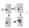
- The error diffusion process itself consists of three steps. First, a modified input is formed as the sum of the original input value and the diffused past errors (located above and left of the current pixel). In the second step, this modified error is rounded to yield the output. As the last step, the quantization error (rest of fractional part) is calculated as the difference between the modified input and the final output. Then, this quantization error will be spread to the neighbouring pixels by weighting it with a coefficient that can be chosen in various ways.
- Fig. 2 illustrates this principle. At the first stage of the example, the value of the current pixel is 4.5. Then, this value is rounded to 4 generating an error of 0.5. This error will be diffused on three neighboring pixels using three different coefficients (0.5 for the right pixel, 0.3 for the bottom right and 0.2 for the bottom one).
- Normally, the coefficients are chosen in order to keep the energy constant (sum of coefficient is 1). This is mandatory to keep a good stability in the picture. After these steps, the values of three pixels have changed:


- Then, the process will continue with the current pixel having the value 5.1.
- The main disadvantage of the concept is its dependency from the picture content. Indeed the spread error depends on the value of the current pixel and its effect is only visible on its neighbors and is thus picture dependent. Moreover, the rendition of very low levels is based on some spread pixels far from each other since the spread error is too small to have rapid effect. Finally the effect is more a noise on a low level than a real visible level.
- On the one hand, there is a multi-mask cell-based matrix dithering able to render 3 bits of fractional part in a quite invisible way, on the other hand up to 10 bits are mandatory to have a greyscale quality similar to CRT standards. Moreover, the error diffusion alone is able to render more levels but in such a noisy way that the final picture quality is not enhanced as it could be: the results will be only good at a very long viewing distance that is not the main application for very large screens today.
- A combination of error diffusion and multi-mask dithering might help to render more bits of fractional part if one can keep the major advantages of both co n-cepts: quite invisible dithering pattern with more bits (8 bits will be studied as example in the following parts of this document).
- A simple possibility for combining these algorithms is shown in Fig. 3
- The general representation "8.8 bits" means 8-bit integer and 8-bit fractional part. Since the 8 bits of the fractional part shall be handled differently, they will be decomposed in the 3 MSBs followed by 5 LSBs described as "3.5". Finally, the 16-bits of information are described under the form 8.3.5 bits.
- In the case of Fig. 3, the 8 bits of video information are forwarded to a
degamma block 1. Thisblock 1 will perform the quadratic degamma function with 16 bits resolution in order to deliver 8.3.5 bits of information. The 5 lowest bits will be diffused inblock 2 following a standard error diffusion principle as explained before. Therefore, after thisblock 2, there are only 8.3 bits of information (5 LSBs being diffused before, symbolized by adder 3). The 3bits of the fractional part are used to select theappropriate mask 4 from themulti-mask dithering function display 7. - The concept described here is simple and obvious. However, it does not work properly. Indeed, in this concept both ditherings are applied independently one after the other. This lies in some kind of interferences on the screen in the form of vertical or diagonal periodical structures. These periodical structures are quite annoying and disable a great part of the dithering function so that finally, the rendition of the fractional part does not achieve the 8 target bits.
- In view of that it is the object of the present invention to provide a method and a device for processing video data which guarantee a better picture quality.
- According to the present invention this object is solved by a method for processing video data for display on a display device having a plurality of luminous elements corresponding to the pixels of a picture, wherein the time of a video frame or field is divided into a plurality of sub-fields during which the luminous elements can be activated for light emission in small pulses corresponding to a sub-field code word of n bits used for encoding the p possible video levels lighting a pixel, comprising the steps of:
- performing cell-based, pixel-based or multi-mask dithering for reducing a quantization error, said dithering outputting a dither value "1" or "0" for each pixel or cell, a cell being a luminous element of a pixel, and performing an error diffusion for each pixel or cell for reducing the quantization error, wherein the error diffusion for a pixel or cell, during error diffusion, is added to the value of said pixel or cell if the dither value is equal to "1".
- Furthermore, there is provided a device for processing video data for display on a display device having a plurality of luminous elements corresponding to the pixels of a picture, wherein the time of a video frame or field is divided into a plurality of sub-fields during which the luminous elements can be activated for light emission in small pulses corresponding to a sub-field code word of n bits used for encoding the p possible video levels lighting a pixel, comprising: dithering means for performing cell-based, pixel-based or multi-mask dithering in order to reduce a quantization error, said dithering outputting a dither value "1" or "0" for each pixel or cell, a cell being a luminous element of a pixel, and diffusion means for performing error diffusion also in order to reduce the quantization error, wherein an output signal of said dithering means is fed to said diffusion means so that the error diffusion for a pixel or cell is added to the value of said pixel or cell if the dither value is equal to "1".
- Advantageously, the error diffusion is applied under the control of the cell-based pixel-based or multi-mask dithering. Thus, a annoying artefacts can be avoided.
- The error diffusion for a pixel or a cell is performed if the value of dithering is "1". Since the values of dithering usually are "0" or "1" these values can also be used as switching bits.
- The code words should be processed with more than n bits, so that fractional parts of code words can be formed, and the error diffusion is applicable on all bits of a fractional part. However, best results are obtained, if the result of a cell-based, pixel-based or multi-mask dithering is used as switching parameter for switching on and off the error diffusion.
- Particularly, the highest bit or a couple of the highest bits of a fractional part may be used for determining the value of the cell-based, pixel-based or multi-mask dithering. Thus, only larger quantization errors initiate an error diffusion, whereas the error diffusion for smaller quantization errors may be accumulated for one cell or one pixel. Thus, error diffusion can be performed depending on the content of the picture. If an error is not diffused it may be stored for a future pixel.
- The error to be added to a pixel or a cell by error diffusion may be limited to a maximum error. Preferably, such maximum error is 1. This limitation guarantees that the error does not increase unduly.
- The present invention will now be described in more detail along with the following drawings, showing in:
- Fig. 1
- the principle of pixel-based and cell-based dithering;
- Fig. 2
- the principle of error diffusion;
- Fig. 3
- a block diagram of the combination of multi-mask dithering and error diffusion;
- Fig. 4
- a block diagram of an improved combination of multi-mask dithering and error diffusion according to a first embodiment of the present invention; and
- Fig. 5
- a block diagram of a second embodiment of the present invention
- The main issue of combining the error diffusion with the multi-mask/cell-based dithering should be to achieve a rendition of more bits of fractional part while keeping the advantage of a structure of dithering similar to the multi-mask. According to the present invention this is achieved by a diffusion of all 8 bits of fractional part but the error will only be applied on cells having their multi-mask value at 1. In order to determine the value of the multi-mask, the three highest bits of the fractional part will be chosen. This concept is illustrated in Fig. 4.
- The
input 8 bits of video information are forwarded to thedegamma block 1. Thisblock 1 will perform the quadratic function with 16 bits resolution in order to deliver 8.3.5 bits of information. The complete information is input into anerror diffusion block 2 thereby passing an adder 3'. The 3 MSBs of the fractional part of the output from thedegamma block 1 are used to define the output of the multi-mask dithering 4', this being 1 or 0. Aswith 8 is controlled by the output of the multi-mask block 4'. In case of 1, the error diffused to this pixel is accepted and added by adder 3' to the pixel before going to theerror diffusion block 2. If the output of the multi-mask 4' is 0, the diffused error is refused, and will be re-injected viaswitch 8 inside theerror diffusion block 2. The resulting diffused error xe' and the fractional part ye' are:
and
- The error diffusion will only be applied in a multi-mask matrix manner keeping all advantages of this concept. On the other hand, the value applied in a multi-mask manner, is 8-bit fractional and follows the error diffusion principle.
- As illustrated in Fig. 4 the error diffused can be up to 1.8 bits since the error can be accumulated on a higher number of iterations (if often rejected).
- If we use the masks defined by the table given in the preamble of the present specification, a circular permutation should be done in order to add the error at the right place :
- Input between x.000 and x.125 → mask 1 (mask corresponding to
level 1/8 in the table of the preamble) - Input between x.125 and x.250 → mask 2 (mask corresponding to
level 1/4 in the table of the preamble) - Input between x.250 and x.375 → mask 3(mask corresponding to
level 3/8 in the table of the preamble) - Input between x.375 and x.500 → mask 4(mask corresponding to
level 1/2 in the table of the preamble) - Input between x.500 and x.625 → mask 5(mask corresponding to
level 5/8 in the table of the preamble) - Input between x.625 and x.750 → mask 6(mask corresponding to
level 3/4 in the table of the preamble) - Input between x.750 and x.875 → mask 7(mask corresponding to
level 7/8 in the table of the preamble) - Input between x.875 and 1 → mask 8 (mask full of 1)
- An improved embodiment of the invention is shown in Fig. 5. Since the error diffused to one pixel can be, depending on the multi-mask value, re-injected inside the
error diffusion block 2, it is easy to understand that the error can increase a lot. Therefore, an improvement of the concept will be to limit the error that can be added to the current pixel to a maximum by a limiter 9. The rest being re-injected again inside the error diffusion block as shown in Figure 5. - The updated concept is similar to the previous one, excepted the fact that the error added to the pixel is limited to 1.0, the rest being re-injected again in the
error diffusion block 2 as described below:
- The above described embodiments are directed to a PDP. However, any other kind of digital display may profit from the present invention.
Claims (8)
- Method for processing video data for display on a display device (7) having a plurality of luminous elements corresponding to the pixels of a picture, wherein the time of a video frame or field is divided into a plurality of sub-fields during which the luminous elements can be activated for light emission in small pulses corresponding to a sub-field code word of n bits used for encoding the p possible video levels lighting a pixel, comprising the steps of:- performing cell-based, pixel-based or multi-mask dithering (4') for reducing a quantization error, said dithering outputting a dither value "1" or "0" for each pixel or cell, a cell being a luminous element of a pixel, and- performing an error diffusion (2) for each pixel or cell for reducing the quantization error,
characterized in that- the error diffusion (2) for a pixel or cell, during error diffusion, is added to the value of said pixel or cell if the dither value is equal to "1". - Method according to one of the preceding claims, wherein the code words are processed with more than n bits, so that values lying between the values of rendered code words can be formed, and the error diffusion (2) is applied on all bits of each of these values.
- Method according to claim 2, wherein the highest bit or a couple of the highest bits of a fractional part is/are used for determining the value of said dithering.
- Method according to one of the preceding claims, wherein a diffused error is accumulated for one cell or pixel.
- Method according to one of the preceding claims, wherein the error to be added to a pixel or cell by error diffusion (2) is limited to a maximum error.
- Method according to claim 5, wherein the maximum error is 1.
- Device for processing video data for display on a display device (7) having a plurality of luminous elements corresponding to the pixels of a picture, wherein the time of a video frame or field is divided into a plurality of sub-fields during which the luminous elements can be activated for light emission in small pulses corresponding to a sub-field code word of n bits used for encoding the p possible video levels lighting a pixel, comprising:- dithering means (4') for performing cell-based, pixel-based or multi-mask dithering in order to reduce a quantization error, said dithering outputting a dither value "1" or "0" for each pixel or cell, a cell being a luminous element of a pixel, and- diffusion means (2) for performing error diffusion also in order to reduce the quantization error
characterized in that- an output signal of said dithering means (4') is fed to said diffusion means (2) so that the error diffusion (2) for a pixel or cell is added to the value of said pixel or cell if the dither value is equal to "1". - Device according to claim 7, wherein a diffused error is accumulatable for one cell or pixel.
Priority Applications (1)
| Application Number | Priority Date | Filing Date | Title |
|---|---|---|---|
| EP20050106222 EP1619649B1 (en) | 2004-07-23 | 2005-07-07 | Method and device for processing video data by combining error diffusion and another dithering |
Applications Claiming Priority (3)
| Application Number | Priority Date | Filing Date | Title |
|---|---|---|---|
| EP04291878A EP1619651A1 (en) | 2004-07-23 | 2004-07-23 | Method and device for processing video data by combining error diffusion and dithering |
| EP04023434 | 2004-10-01 | ||
| EP20050106222 EP1619649B1 (en) | 2004-07-23 | 2005-07-07 | Method and device for processing video data by combining error diffusion and another dithering |
Publications (3)
| Publication Number | Publication Date |
|---|---|
| EP1619649A2 true EP1619649A2 (en) | 2006-01-25 |
| EP1619649A3 EP1619649A3 (en) | 2008-02-13 |
| EP1619649B1 EP1619649B1 (en) | 2012-09-26 |
Family
ID=35276322
Family Applications (1)
| Application Number | Title | Priority Date | Filing Date |
|---|---|---|---|
| EP20050106222 Ceased EP1619649B1 (en) | 2004-07-23 | 2005-07-07 | Method and device for processing video data by combining error diffusion and another dithering |
Country Status (1)
| Country | Link |
|---|---|
| EP (1) | EP1619649B1 (en) |
Family Cites Families (3)
| Publication number | Priority date | Publication date | Assignee | Title |
|---|---|---|---|---|
| JP3354741B2 (en) * | 1995-04-17 | 2002-12-09 | 富士通株式会社 | Halftone display method and halftone display device |
| EP1262947B1 (en) * | 2001-06-01 | 2013-10-09 | Thomson Licensing | Method and apparatus for processing video picture data for a display device |
| KR100552908B1 (en) * | 2003-12-16 | 2006-02-22 | 엘지전자 주식회사 | Driving method and driving apparatus of plasma display panel |
-
2005
- 2005-07-07 EP EP20050106222 patent/EP1619649B1/en not_active Ceased
Also Published As
| Publication number | Publication date |
|---|---|
| EP1619649B1 (en) | 2012-09-26 |
| EP1619649A3 (en) | 2008-02-13 |
Similar Documents
| Publication | Publication Date | Title |
|---|---|---|
| US7312767B2 (en) | Method and device for compensating burn-in effects on display panels | |
| EP1256924B1 (en) | Method and apparatus for processing video pictures | |
| EP1536400B1 (en) | Method for processing a gray level in a plasma display panel and apparatus using the same | |
| US20070030285A1 (en) | Method and device for processing video data for display on a display device | |
| US7738719B2 (en) | Method and device for processing video data by combining error diffusion and another dithering | |
| KR100552908B1 (en) | Driving method and driving apparatus of plasma display panel | |
| US20010005186A1 (en) | Method of and unit for displaying an image in sub-fields | |
| US20060125718A1 (en) | Adaptive noise reduction for digital display panels | |
| US7609235B2 (en) | Multiscan display on a plasma display panel | |
| EP1615199A2 (en) | Plasma display apparatus and image processing method thereof | |
| EP1619651A1 (en) | Method and device for processing video data by combining error diffusion and dithering | |
| US7729557B2 (en) | Method and device for processing video data to be displayed on a display device | |
| EP1619649B1 (en) | Method and device for processing video data by combining error diffusion and another dithering | |
| US20060221239A1 (en) | Method and device for processing video data for display on a display device | |
| JP4032737B2 (en) | Image processing device | |
| EP1522964B1 (en) | Method for processing video pictures for false contours and dithering noise compensation | |
| US7633468B2 (en) | Image processing apparatus and method of plasma display panel | |
| KR20070035885A (en) | Image processing method of plasma display device | |
| JP3518205B2 (en) | Image display device | |
| KR100738816B1 (en) | Image processing apparatus and image processing method of plasma display panel | |
| KR20070022596A (en) | Method and device for processing video data to be displayed on a display device | |
| KR100625548B1 (en) | Image processing apparatus and image processing method of plasma display panel | |
| KR100579933B1 (en) | Image processing apparatus and image processing method of plasma display panel | |
| KR100625476B1 (en) | Plasma Display Device and Image Processing Method | |
| KR100625549B1 (en) | Image Processing Method of Plasma Display Panel |
Legal Events
| Date | Code | Title | Description |
|---|---|---|---|
| PUAI | Public reference made under article 153(3) epc to a published international application that has entered the european phase |
Free format text: ORIGINAL CODE: 0009012 |
|
| AK | Designated contracting states |
Kind code of ref document: A2 Designated state(s): AT BE BG CH CY CZ DE DK EE ES FI FR GB GR HU IE IS IT LI LT LU LV MC NL PL PT RO SE SI SK TR |
|
| AX | Request for extension of the european patent |
Extension state: AL BA HR MK YU |
|
| PUAL | Search report despatched |
Free format text: ORIGINAL CODE: 0009013 |
|
| AK | Designated contracting states |
Kind code of ref document: A3 Designated state(s): AT BE BG CH CY CZ DE DK EE ES FI FR GB GR HU IE IS IT LI LT LU LV MC NL PL PT RO SE SI SK TR |
|
| AX | Request for extension of the european patent |
Extension state: AL BA HR MK YU |
|
| RIC1 | Information provided on ipc code assigned before grant |
Ipc: G09G 3/28 20060101AFI20080109BHEP Ipc: G09G 3/20 20060101ALI20080109BHEP |
|
| 17P | Request for examination filed |
Effective date: 20080808 |
|
| AKX | Designation fees paid |
Designated state(s): DE FR GB |
|
| 17Q | First examination report despatched |
Effective date: 20081013 |
|
| GRAP | Despatch of communication of intention to grant a patent |
Free format text: ORIGINAL CODE: EPIDOSNIGR1 |
|
| GRAS | Grant fee paid |
Free format text: ORIGINAL CODE: EPIDOSNIGR3 |
|
| GRAA | (expected) grant |
Free format text: ORIGINAL CODE: 0009210 |
|
| AK | Designated contracting states |
Kind code of ref document: B1 Designated state(s): DE FR GB |
|
| REG | Reference to a national code |
Ref country code: GB Ref legal event code: FG4D |
|
| REG | Reference to a national code |
Ref country code: DE Ref legal event code: R084 Ref document number: 602005036253 Country of ref document: DE |
|
| REG | Reference to a national code |
Ref country code: DE Ref legal event code: R096 Ref document number: 602005036253 Country of ref document: DE Effective date: 20121122 |
|
| REG | Reference to a national code |
Ref country code: DE Ref legal event code: R084 Ref document number: 602005036253 Country of ref document: DE Effective date: 20120929 |
|
| PLBE | No opposition filed within time limit |
Free format text: ORIGINAL CODE: 0009261 |
|
| STAA | Information on the status of an ep patent application or granted ep patent |
Free format text: STATUS: NO OPPOSITION FILED WITHIN TIME LIMIT |
|
| 26N | No opposition filed |
Effective date: 20130627 |
|
| REG | Reference to a national code |
Ref country code: DE Ref legal event code: R097 Ref document number: 602005036253 Country of ref document: DE Effective date: 20130627 |
|
| GBPC | Gb: european patent ceased through non-payment of renewal fee |
Effective date: 20130707 |
|
| PG25 | Lapsed in a contracting state [announced via postgrant information from national office to epo] |
Ref country code: GB Free format text: LAPSE BECAUSE OF NON-PAYMENT OF DUE FEES Effective date: 20130707 |
|
| REG | Reference to a national code |
Ref country code: FR Ref legal event code: PLFP Year of fee payment: 12 |
|
| REG | Reference to a national code |
Ref country code: FR Ref legal event code: PLFP Year of fee payment: 13 |
|
| REG | Reference to a national code |
Ref country code: DE Ref legal event code: R082 Ref document number: 602005036253 Country of ref document: DE Representative=s name: DEHNS, DE Ref country code: DE Ref legal event code: R082 Ref document number: 602005036253 Country of ref document: DE Representative=s name: DEHNS PATENT AND TRADEMARK ATTORNEYS, DE Ref country code: DE Ref legal event code: R082 Ref document number: 602005036253 Country of ref document: DE Representative=s name: HOFSTETTER, SCHURACK & PARTNER PATENT- UND REC, DE |
|
| REG | Reference to a national code |
Ref country code: FR Ref legal event code: PLFP Year of fee payment: 14 |
|
| REG | Reference to a national code |
Ref country code: DE Ref legal event code: R082 Ref document number: 602005036253 Country of ref document: DE Representative=s name: DEHNS, DE Ref country code: DE Ref legal event code: R081 Ref document number: 602005036253 Country of ref document: DE Owner name: INTERDIGITAL CE PATENT HOLDINGS, FR Free format text: FORMER OWNER: DEUTSCHE THOMSON BRANDT, GMBH, 78048 VILLINGEN-SCHWENNINGEN, DE Ref country code: DE Ref legal event code: R081 Ref document number: 602005036253 Country of ref document: DE Owner name: INTERDIGITAL CE PATENT HOLDINGS, FR Free format text: FORMER OWNER: DEUTSCHE THOMSON-BRANDT GMBH, PATENT- UND LIZENZABTEILUNG, 30453 HANNOVER, DE Ref country code: DE Ref legal event code: R082 Ref document number: 602005036253 Country of ref document: DE Representative=s name: DEHNS PATENT AND TRADEMARK ATTORNEYS, DE |
|
| PGFP | Annual fee paid to national office [announced via postgrant information from national office to epo] |
Ref country code: FR Payment date: 20200728 Year of fee payment: 16 Ref country code: DE Payment date: 20200729 Year of fee payment: 16 |
|
| REG | Reference to a national code |
Ref country code: DE Ref legal event code: R119 Ref document number: 602005036253 Country of ref document: DE |
|
| PG25 | Lapsed in a contracting state [announced via postgrant information from national office to epo] |
Ref country code: DE Free format text: LAPSE BECAUSE OF NON-PAYMENT OF DUE FEES Effective date: 20220201 |
|
| PG25 | Lapsed in a contracting state [announced via postgrant information from national office to epo] |
Ref country code: FR Free format text: LAPSE BECAUSE OF NON-PAYMENT OF DUE FEES Effective date: 20210731 |