EP1619558A2 - Power coupling device and image forming apparatus having the same - Google Patents
Power coupling device and image forming apparatus having the same Download PDFInfo
- Publication number
- EP1619558A2 EP1619558A2 EP05253826A EP05253826A EP1619558A2 EP 1619558 A2 EP1619558 A2 EP 1619558A2 EP 05253826 A EP05253826 A EP 05253826A EP 05253826 A EP05253826 A EP 05253826A EP 1619558 A2 EP1619558 A2 EP 1619558A2
- Authority
- EP
- European Patent Office
- Prior art keywords
- coupler
- coupler member
- driving
- driven
- connection
- Prior art date
- Legal status (The legal status is an assumption and is not a legal conclusion. Google has not performed a legal analysis and makes no representation as to the accuracy of the status listed.)
- Withdrawn
Links
Images




Classifications
-
- G—PHYSICS
- G03—PHOTOGRAPHY; CINEMATOGRAPHY; ANALOGOUS TECHNIQUES USING WAVES OTHER THAN OPTICAL WAVES; ELECTROGRAPHY; HOLOGRAPHY
- G03G—ELECTROGRAPHY; ELECTROPHOTOGRAPHY; MAGNETOGRAPHY
- G03G15/00—Apparatus for electrographic processes using a charge pattern
- G03G15/75—Details relating to xerographic drum, band or plate, e.g. replacing, testing
- G03G15/757—Drive mechanisms for photosensitive medium, e.g. gears
-
- F—MECHANICAL ENGINEERING; LIGHTING; HEATING; WEAPONS; BLASTING
- F16—ENGINEERING ELEMENTS AND UNITS; GENERAL MEASURES FOR PRODUCING AND MAINTAINING EFFECTIVE FUNCTIONING OF MACHINES OR INSTALLATIONS; THERMAL INSULATION IN GENERAL
- F16D—COUPLINGS FOR TRANSMITTING ROTATION; CLUTCHES; BRAKES
- F16D1/00—Couplings for rigidly connecting two coaxial shafts or other movable machine elements
- F16D1/10—Quick-acting couplings in which the parts are connected by simply bringing them together axially
- F16D1/101—Quick-acting couplings in which the parts are connected by simply bringing them together axially without axial retaining means rotating with the coupling
-
- G—PHYSICS
- G03—PHOTOGRAPHY; CINEMATOGRAPHY; ANALOGOUS TECHNIQUES USING WAVES OTHER THAN OPTICAL WAVES; ELECTROGRAPHY; HOLOGRAPHY
- G03G—ELECTROGRAPHY; ELECTROPHOTOGRAPHY; MAGNETOGRAPHY
- G03G15/00—Apparatus for electrographic processes using a charge pattern
- G03G15/01—Apparatus for electrographic processes using a charge pattern for producing multicoloured copies
- G03G15/0105—Details of unit
- G03G15/0121—Details of unit for developing
-
- G—PHYSICS
- G03—PHOTOGRAPHY; CINEMATOGRAPHY; ANALOGOUS TECHNIQUES USING WAVES OTHER THAN OPTICAL WAVES; ELECTROGRAPHY; HOLOGRAPHY
- G03G—ELECTROGRAPHY; ELECTROPHOTOGRAPHY; MAGNETOGRAPHY
- G03G15/00—Apparatus for electrographic processes using a charge pattern
- G03G15/01—Apparatus for electrographic processes using a charge pattern for producing multicoloured copies
- G03G15/0142—Structure of complete machines
- G03G15/0178—Structure of complete machines using more than one reusable electrographic recording member, e.g. one for every monocolour image
-
- G—PHYSICS
- G03—PHOTOGRAPHY; CINEMATOGRAPHY; ANALOGOUS TECHNIQUES USING WAVES OTHER THAN OPTICAL WAVES; ELECTROGRAPHY; HOLOGRAPHY
- G03G—ELECTROGRAPHY; ELECTROPHOTOGRAPHY; MAGNETOGRAPHY
- G03G21/00—Arrangements not provided for by groups G03G13/00 - G03G19/00, e.g. cleaning, elimination of residual charge
- G03G21/16—Mechanical means for facilitating the maintenance of the apparatus, e.g. modular arrangements
- G03G21/18—Mechanical means for facilitating the maintenance of the apparatus, e.g. modular arrangements using a processing cartridge, whereby the process cartridge comprises at least two image processing means in a single unit
- G03G21/1839—Means for handling the process cartridge in the apparatus body
- G03G21/1857—Means for handling the process cartridge in the apparatus body for transmitting mechanical drive power to the process cartridge, drive mechanisms, gears, couplings, braking mechanisms
- G03G21/1864—Means for handling the process cartridge in the apparatus body for transmitting mechanical drive power to the process cartridge, drive mechanisms, gears, couplings, braking mechanisms associated with a positioning function
-
- G—PHYSICS
- G03—PHOTOGRAPHY; CINEMATOGRAPHY; ANALOGOUS TECHNIQUES USING WAVES OTHER THAN OPTICAL WAVES; ELECTROGRAPHY; HOLOGRAPHY
- G03G—ELECTROGRAPHY; ELECTROPHOTOGRAPHY; MAGNETOGRAPHY
- G03G2215/00—Apparatus for electrophotographic processes
- G03G2215/01—Apparatus for electrophotographic processes for producing multicoloured copies
- G03G2215/0103—Plural electrographic recording members
- G03G2215/0119—Linear arrangement adjacent plural transfer points
Definitions
- the present invention relates to a coupling device. More particularly, the present invention relates to a power coupling device for transmitting power between a driving unit of an organic photoconductor (OPC) of an electrophotographic image forming apparatus, and an image forming apparatus having the same.
- OPC organic photoconductor
- Electrophotographic image forming apparatuses include a photocopier, a printer, a facsimile and a word processor.
- an electrostatic latent image is formed by exposing a photoconductive medium evenly electrified by an electrifying unit to a laser for forming an image.
- the electrostatic latent image is developed into a toner image by a developing unit having a toner.
- the toner image is transferred onto a recording medium by a transfer unit, thereby forming an image.
- electrostatic latent images are formed on a plurality of photoconductive mediums for different colors, such as magenta, cyan, yellow and black, and developed by the respectively different colors of toner.
- the toner images of different colors are overlapped and transferred onto an intermediate recording medium, such as an intermediate transfer belt.
- the transferred intermediate toner images are transferred onto a final recording medium, thereby forming a color image on the final recording medium.
- the intermediate transfer belt or the photoconductive mediums of different colours are expendables that have limited lifespans, they need to be replaced at the end of the expendable's lifespans.
- image forming apparatuses have been provided with a process cartridge removably mounted in a main body thereof, wherein expendables such as the photoconductive medium, the electrifying unit, the developing unit and a cleaning unit are all integrated as one part.
- the process cartridge is removably mounted in the image forming apparatus by a driving unit for supplying power and a coupling device.
- FIG. 1 schematically shows a conventional power coupling device of an image forming apparatus.
- the conventional power coupling device comprises a driving coupler 10 and a driven coupler 20.
- the driving coupler 10 is rotatably mounted in a driving unit 1 in the image forming apparatus.
- the driving coupler 10 comprises a coupling recess 11 depressed by a certain depth and having a non-circular section, and a positioning recess 12 formed at one side of the coupling recess 11.
- the driven coupler 20 comprises a coupling protrusion 21 fixed at one side of a photoconductive drum 2 and protruding by a certain height to correspond to the coupling recess 11, and a positioning protrusion 22.
- the driving coupler 10 and the driven coupler 20 are provided in different colours, and the power of the driving unit 1 can be transmitted to the respective photoconductive mediums 2 by coupling of the driving coupler 10 and the driven coupler 20, thereby rotating the photoconductive medium 2.
- peak eccentric positions are checked, such as where radiuses of the respective photoconductive mediums 2 are the greatest, and the driven coupler 20 is fixed to the respective photoconductive mediums 2 in a manner that the positioning protrusion 22 of the driven coupler 20, for example, is located at the peak eccentric position, such that the photoconductive mediums 2 are coupled with the driving unit at the same phase.
- the offset occurs with respect to the standard, the offset among the respective colours decreases. Therefore, the visual colour registration seems insignificant.
- the colour registration in consideration of the manufacturing error and the forming error can be compensated, however, the assembly error (for example, an error of a distance between the centers of the photoconductive mediums) may not be considered in compensating the colour registration. Therefore, improvement in image quality is limited.
- the present invention addresses at least some of the above problems and/or disadvantages and provides at least some of the advantages described below.
- the present invention provides an improved power coupling device capable of compensating colour registration taking account of an assembly error as well as a manufacturing error and a forming error, without requiring an automatic controller having a complicated structure, and an image forming apparatus having the same.
- a power coupling device in which one of a driving coupler and a driven coupler provided in a driving part comprises a first coupler member and a second coupler member that are connected by a connection means.
- the power coupling device comprises a driving coupler mounted in the driving part and further comprises a first connection part and a first positioning part formed at one side of the first connection part, a driven coupler mounted in the driven part and a second connection part and a second positioning part respectively corresponding to the first connection part and the first positioning part.
- the driven coupler comprises a first coupler member fixed to the driven part, a second coupler member having the second connection part and the second positioning part for connection with the first coupler member, and a connection means for connecting the first coupler member with the second coupler member so that a connecting position of the second coupler member with respect to the first coupler member can be controlled (adjusted).
- connection means comprises a plurality of projections formed at one of the first and the second coupler members, and a plurality of depressions formed at the other one of the first and the second coupler members.
- the projections and the depressions may be formed by pins and pin holes, respectively.
- the projections and the depressions may be formed by square columns and square depressions, respectively, or any other suitable shape.
- the driven part comprises a rotation shaft
- the first coupler member is fixed to the rotation shaft by a D-cut part, a pin, or a key.
- the driven part has a peak eccentric position
- the second coupler member is positioned with respect to the first coupler member so that the second positioning part thereof corresponds to the peak eccentric position
- the driven part is a photoconductive medium
- the driving part is a driving unit of an image forming apparatus.
- the first connection part of the driving coupler has a non-circular section.
- the first connection part of the driving coupler is formed as a substantially triangular recess
- the second connection part of the driven coupler is formed as a substantially triangular protrusion to correspond to the recess.
- the reverse structure may also be adopted.
- the first positioning part of the driving coupler is formed as a recess
- the second positioning part of the driven coupler is formed as a protrusion.
- the structure can also be in reverse.
- a power coupling device for transferring the power of a driving part to a driven part, comprising a driving coupler mounted in the driving part and comprising a first connection part and a first positioning part formed at one side of the first connection part, and a driven coupler mounted in the driven part and comprising a second connection part and a second positioning part respectively corresponding to the first connection part and the first positioning part, wherein the driving coupler comprises a first coupler member fixed to the driving part, a second coupler member having the first connection part and the first positioning part for connection with the first coupler member, and a connection means for connecting the first coupler member with the second coupler member so that a connecting position of the second coupler member with respect to the first coupler member can be controlled (adjusted).
- an image forming apparatus comprising four photoconductive mediums for four different colours, being removably mounted in a main body thereof, a driving unit having four driving couplers for four different colours, the driving couplers comprising a first connection part depressed by a certain depth and having a non-circular section and a first positioning part formed at one side of the first connection part, so as to rotate the photoconductive mediums, and four driven couplers for four different colours, respectively mounted at the four photoconductive mediums to be coupled with the respective driving couplers.
- the four driven couplers respectively comprise a first coupler member fixed to the photoconductive medium, a second coupler member having the second connection part and the second positioning part corresponding to the first connection part and the first positioning part and connected with the first coupler member, and a connection means for connecting the first coupler member with the second coupler member so that a connecting position of the second coupler member with respect to the first coupler member can be controlled, and the four second coupler members are positioned with respect to the first coupler member so that the second positioning parts thereof correspond to the peak eccentric position of the photoconductive mediums, respectively.
- the colour registration can be compensated in consideration of even the assembly errors as well as the manufacturing errors and the forming errors of the photoconductive medium, and the image quality can be considerably improved.
- FIGS. 2A and 2B illustrate a power coupling device of an image forming apparatus according to an embodiment of the present invention.
- a reference number 100 denotes a driving unit as a driving part
- 200 denotes a driving coupler
- 300 denotes a photoconductive medium as a driven part
- 400 denotes a driven coupler.
- the driving coupler 200 is provided to the driving unit 100 in the image forming apparatus and comprises a first connection part 210 depressed by a certain depth and having a non-circular section and a first positioning part 220 formed at one side of the first connection part 210, which is formed as a recess.
- the section of the first connection part 210 is substantially formed as a triangle in this embodiment, any other non-circular shape can also be applied.
- the driven coupler 400 is mounted at one side of the photoconductive medium 300.
- the driven coupler 400 comprises a second connection part 410 and a second positioning part 420 to respectively correspond to the first connection part 210 and the first positioning part 220 of the driving coupler 200.
- the second connection part 420 is preferably protruded by a certain height and has a non-circular section, and the second positioning part 420 is protruded at one side of the second connection part 410.
- the driven coupler 400 comprises a first coupler member 430, a second coupler member 440 and a connection means 450.
- the first coupler member 430 is fixed to a shaft 310 of the photoconductive medium 300, and the second coupler member 440 is connected to the first coupler member 430 such that the connecting position can be adjusted by the connection means 450.
- the first coupler member 430 may be fixed to the shaft 310 by a D-cut part 431, by a pin, a key or other suitable fixing means.
- the second coupler member 440 comprises the second connection part 410 and the second positioning part 420.
- connection means 450 conjoins the first and the second coupler members 430 and 440, so that the connecting position of the second coupler member 430 with respect to the first coupler member 430 is adjustable.
- connection means 450 comprises a plurality of projections 451 preferably formed on the first coupler member 430 and a plurality of depressions 452 preferably formed on the second coupler member 440 for the projections 451 to be correspondingly fit therein.
- the projections 451 and the depressions 452 may be formed in reverse or any other suitable fashion to connect the two members together.
- the projections 451 and the depressions 452 may be implemented by pins and pin holes, however, the present invention is not limited to this embodiment. As shown in Figures 3 and 4, the projections 451 and the depressions 452 may be formed by square columns and square depressions or configured in other ways. The projections 451 and the depressions 452 can be connected in any projecting and depressing structures, including alternating depressions and projections, as long as the connection position thereof can be adjusted.
- the second coupler member 440 is connected using the above connection means 450 so that the second positioning part 420 thereof is located at the peak eccentric position of the photoconductive medium.
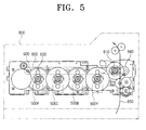
- Figure 5 is a view schematically illustrating an image forming apparatus employing the power coupling device according to an embodiment of the present invention
- Figure 6 is a perspective view showing main parts of Figure 5.
- the image forming apparatus comprises a driving unit 100, photoconductive mediums 300K, 300C, 300M and 300Y of four colours, developing units 500K, 500C, 500M and 500Y of four colours, an intermediate transfer belt 600 as an intermediate transfer medium and a power coupling device 700.
- the driving unit 100 comprises a driving source 110, and driving couplers 200K, 200C, 200M and 200Y of four colours, which are rotated by the driving source 110. Since the driving couplers have been described hereinbefore, detailed description thereof will not be repeated.
- the photoconductive mediums 300K, 300C, 300M and 300Y of four colours are disposed in a main body 800 (shown in Figure 5) of the image forming apparatus in a certain order of colours. In this embodiment, they are arranged in an order of K (black), C (cyan), M (magenta) and Y (yellow), according to the moving direction of the intermediate transfer belt 600. Also, the driving couplers 200K, 200C, 200M and 200Y and driven couplers 400K, 400C, 400M and 400Y constructing the power coupling device 700 are mounted on one side of the photoconductive mediums 300K, 300C, 300M and 300Y, respectively. A detailed description of the structure of the driven couplers will be omitted since it has been made above.
- the developing units 500K, 500C, 500M and 500Y of four colours are disposed below the respective photoconductive mediums 300K, 300C, 300M and 300Y to form a colour image on the photoconductive mediums 300K, 300C, 300M and 300Y.
- the developing unit is not an essential feature of the present invention and can be understood as well-known art. Therefore, a detailed description of the developing units has been omitted for the sake of clarity.
- the intermediate transfer belt 600 is driven in one direction, being supported by a driving roller 610, a supporting roller 620 and a plurality of T1 rollers 630.
- the intermediate transfer belt 600 is sequentially transferred with the colour images formed on the respective photoconductive mediums 300K, 300C, 300M and 300Y in an overlapping manner. Therefore, a full-colored image is transferred onto the intermediate transfer belt 600 that has finally passed through the photoconductive medium 300Y.
- the full-colored image is transferred to a printing medium 650 that passes between the intermediate transfer belt 600 and a T2 roller 640.
- the driving roller 610 is in connection with the driving unit 100 to receive rotational power and thereby move the intermediate transfer belt 600.
- the respective photoconductive mediums 300K, 300C, 300M and 300Y of the image forming apparatus are hardly ever formed as an exactly circular shape due to either a manufacturing error and a forming error, and inevitably have eccentric portions. Therefore, the second coupler member 440 is connected with the first coupler member 430 by adjusting the connecting position of the second coupler member 440 of the respective driven couplers 400K, 400C, 400M and 400Y with respect to the first coupler member 430, such that unity of the peak eccentric positions are conveniently and correctly performed, which compensates the colour registration in consideration of the manufacturing error and the forming error.
- the second coupler member 440 of the respective driven couplers 400K, 400C, 400M and 400Y is positioned so that a certain point thereof, for example, the second positioning part 420 corresponds to the peak eccentric position of the photoconductive mediums 300K, 300C, 300M and 300Y.
- the second coupler 440 of the respective driven couplers 300C, 300M and 300Y is rotated by a certain angle X°, 2X°, and 3X°, thereby enabling compensation of the colour registration in consideration of the assembly error as well.
- Equation 1 [ 360 ° X ⁇ X ( D - L ) ] / ( ⁇ X D ) wherein, D denotes a diameter of the photoconductive medium, and L denotes a distance between centers of the photoconductive mediums.
- the colour registration can be minimized, thereby improving the image quality.
- the power coupling device and the image forming device having the same are able to control the manufacturing error and/or the forming error of the photoconductive mediums to be generated in every certain period with respect to the moving direction of the intermediate transfer belt 600. Therefore, the quality of the composite colour image can be improved.
- the assembly error is also considered in compensating the colour registration, the image quality can be more enhanced.
- the peak eccentric positions of the photoconductive mediums for respective colours can be regulated more correctly and conveniently without requiring a complicated controlling device or a controlling algorithm, for compensation of the colour registration considering the manufacturing error and the forming error.
- the effort of correctly corresponding the eccentric positions of the driven couplers and the photoconductive mediums to each other, as required when using the conventional photoconductive medium, can be saved. Furthermore, a grouping process for corresponding the peak eccentric positions of the photoconductive mediums is not required, thereby enhancing assembly of the image forming apparatus.
- the power coupling device can include the driving coupler 200 separately comprising first and second coupling members 230 and 240, which are displaceably connected by a connection means 250, as shown in Figures 8A and 8B.
- the driving coupler 200 comprises the first coupler member 230, the second coupler member 240 and the connection means 250.
- the first coupler member 230 is fixed to the driving part 100.
- the second coupler member 240 for connection with the driven coupler 400, has the first connection part 210 and the first positioning part 220.
- the connection means 250 comprises a plurality of protrusions 251 formed at one end of the first and the second coupler member 230 and 240 and a plurality of recesses 252 formed at the other end of the first and the second coupler members 230 and 240.
- the driven coupler 400 comprises the second connection part 410 and the second positioning part 420, which are fixed to the driving part such as the photoconductive medium 300 corresponding to the first connection part 210 and the first positioning part 220 of the driving coupler 200, respectively.
- connection means 250 which is an essential feature of the present embodiment
- the other structures and effects of this embodiment are the same as those described with respect to the other embodiments. Therefore, a detailed description has been omitted for the sake of conciseness.
Landscapes
- Physics & Mathematics (AREA)
- General Physics & Mathematics (AREA)
- Engineering & Computer Science (AREA)
- General Engineering & Computer Science (AREA)
- Mechanical Engineering (AREA)
- Computer Vision & Pattern Recognition (AREA)
- Electrophotography Configuration And Component (AREA)
- Color Electrophotography (AREA)
- Discharging, Photosensitive Material Shape In Electrophotography (AREA)
Abstract
A power coupling device comprises a driving coupler (200) mounted in the driving unit having a first connection part (210) and a first positioning part (220); and a driven coupler (400) mounted in the driven part (300) having a second connection part (410) and a second positioning part (420), respectively. The driven coupler (400) having a first coupler member (430) fixed to the driven part (300); a second coupler member (440) having the second connection part (410) and the second positioning part (420) for connection with the first coupler member (430); and a connection means (450) for connecting the first coupler member (430) with the second coupler member (440) to control the connecting position. The connection means (450) has a plurality of projections (451) formed at one of the first and the second coupler members; and a plurality of depressions (452) formed at the other one of the first and the second coupler members.
Description
- The present invention relates to a coupling device. More particularly, the present invention relates to a power coupling device for transmitting power between a driving unit of an organic photoconductor (OPC) of an electrophotographic image forming apparatus, and an image forming apparatus having the same.
- Electrophotographic image forming apparatuses include a photocopier, a printer, a facsimile and a word processor. In such image forming apparatuses, an electrostatic latent image is formed by exposing a photoconductive medium evenly electrified by an electrifying unit to a laser for forming an image. The electrostatic latent image is developed into a toner image by a developing unit having a toner. The toner image is transferred onto a recording medium by a transfer unit, thereby forming an image.
- In the case of a color image forming apparatus, electrostatic latent images are formed on a plurality of photoconductive mediums for different colors, such as magenta, cyan, yellow and black, and developed by the respectively different colors of toner. The toner images of different colors are overlapped and transferred onto an intermediate recording medium, such as an intermediate transfer belt. The transferred intermediate toner images are transferred onto a final recording medium, thereby forming a color image on the final recording medium.
- Here, since the intermediate transfer belt or the photoconductive mediums of different colours are expendables that have limited lifespans, they need to be replaced at the end of the expendable's lifespans.
- Recently, image forming apparatuses have been provided with a process cartridge removably mounted in a main body thereof, wherein expendables such as the photoconductive medium, the electrifying unit, the developing unit and a cleaning unit are all integrated as one part. The process cartridge is removably mounted in the image forming apparatus by a driving unit for supplying power and a coupling device.
- Figure 1 schematically shows a conventional power coupling device of an image forming apparatus. The conventional power coupling device comprises a
driving coupler 10 and a driven coupler 20. - The
driving coupler 10 is rotatably mounted in a driving unit 1 in the image forming apparatus. Thedriving coupler 10 comprises acoupling recess 11 depressed by a certain depth and having a non-circular section, and apositioning recess 12 formed at one side of the coupling recess 11. - The driven coupler 20 comprises a
coupling protrusion 21 fixed at one side of aphotoconductive drum 2 and protruding by a certain height to correspond to thecoupling recess 11, and apositioning protrusion 22. - Although schematically shown in the drawings, the
driving coupler 10 and the driven coupler 20 are provided in different colours, and the power of the driving unit 1 can be transmitted to the respectivephotoconductive mediums 2 by coupling of thedriving coupler 10 and the driven coupler 20, thereby rotating thephotoconductive medium 2. - In the above-structured image forming apparatus, in order to implement colour registration of high precision by reducing image offset incurred by errors such as a manufacturing error, a forming error and an assembly error, a method is used, which regulates the eccentricities of the respective
photoconductive mediums 2 of different colours. - In other words, peak eccentric positions are checked, such as where radiuses of the respective
photoconductive mediums 2 are the greatest, and the driven coupler 20 is fixed to the respectivephotoconductive mediums 2 in a manner that thepositioning protrusion 22 of the driven coupler 20, for example, is located at the peak eccentric position, such that thephotoconductive mediums 2 are coupled with the driving unit at the same phase. In this case, although the offset occurs with respect to the standard, the offset among the respective colours decreases. Therefore, the visual colour registration seems insignificant. - However, according to the conventional method as described above, it is hard to select and group the
photoconductive mediums 2 having the same peak eccentric positions because the peak eccentric positions of thephotoconductive mediums 2 may change when fixing the drivencoupler 2 to thephotoconductive mediums 2 after measuring the peak eccentric positions of the respectivephotoconductive mediums 2. - Furthermore, using the conventional method, the colour registration in consideration of the manufacturing error and the forming error can be compensated, however, the assembly error (for example, an error of a distance between the centers of the photoconductive mediums) may not be considered in compensating the colour registration. Therefore, improvement in image quality is limited.
- There are other ways for regulating the peak eccentric positions of the photoconductive mediums 2: one is using a driving system and a sensor clutch; and the other is using a plurality of motors corresponding to the number of the photoconductive mediums. In the former way, a certain position of the photoconductive medium is marked to be recognized as a sensor, such that the peak eccentric positions of the respective photoconductive mediums are uniformly driven. In the latter way, the respective photoconductive mediums are separately driven by the plurality of motors without an intermediate clutch.
- However, the conventional methods as described above require an electronic controller or a controlling algorithm with a complicated structure. Therefore, they are not cost-effective or time-effective.
- The present invention addresses at least some of the above problems and/or disadvantages and provides at least some of the advantages described below.
- According to the present invention there is provided devices and an apparatus as set forth in the appended claims. Preferred features of the invention will be apparent from the dependent claims, and the description which follows.
- The present invention provides an improved power coupling device capable of compensating colour registration taking account of an assembly error as well as a manufacturing error and a forming error, without requiring an automatic controller having a complicated structure, and an image forming apparatus having the same.
- In one aspect of the present invention there is provided a power coupling device in which one of a driving coupler and a driven coupler provided in a driving part comprises a first coupler member and a second coupler member that are connected by a connection means.
- Preferably, the power coupling device comprises a driving coupler mounted in the driving part and further comprises a first connection part and a first positioning part formed at one side of the first connection part, a driven coupler mounted in the driven part and a second connection part and a second positioning part respectively corresponding to the first connection part and the first positioning part. The driven coupler comprises a first coupler member fixed to the driven part, a second coupler member having the second connection part and the second positioning part for connection with the first coupler member, and a connection means for connecting the first coupler member with the second coupler member so that a connecting position of the second coupler member with respect to the first coupler member can be controlled (adjusted).
- Preferably, the connection means comprises a plurality of projections formed at one of the first and the second coupler members, and a plurality of depressions formed at the other one of the first and the second coupler members.
- The projections and the depressions may be formed by pins and pin holes, respectively. Alternatively, the projections and the depressions may be formed by square columns and square depressions, respectively, or any other suitable shape.
- Preferably, the driven part comprises a rotation shaft, and the first coupler member is fixed to the rotation shaft by a D-cut part, a pin, or a key.
- Preferably, the driven part has a peak eccentric position, and the second coupler member is positioned with respect to the first coupler member so that the second positioning part thereof corresponds to the peak eccentric position.
- Preferably, the driven part is a photoconductive medium, and the driving part is a driving unit of an image forming apparatus.
- Preferably, the first connection part of the driving coupler has a non-circular section.
- Preferably, the first connection part of the driving coupler is formed as a substantially triangular recess, and the second connection part of the driven coupler is formed as a substantially triangular protrusion to correspond to the recess. The reverse structure may also be adopted.
- Preferably, the first positioning part of the driving coupler is formed as a recess, and the second positioning part of the driven coupler is formed as a protrusion. Alternatively, the structure can also be in reverse.
- In another aspect of the present invention, there is provided a power coupling device for transferring the power of a driving part to a driven part, comprising a driving coupler mounted in the driving part and comprising a first connection part and a first positioning part formed at one side of the first connection part, and a driven coupler mounted in the driven part and comprising a second connection part and a second positioning part respectively corresponding to the first connection part and the first positioning part, wherein the driving coupler comprises a first coupler member fixed to the driving part, a second coupler member having the first connection part and the first positioning part for connection with the first coupler member, and a connection means for connecting the first coupler member with the second coupler member so that a connecting position of the second coupler member with respect to the first coupler member can be controlled (adjusted).
- In a further aspect of the present invention, there is provided an image forming apparatus comprising four photoconductive mediums for four different colours, being removably mounted in a main body thereof, a driving unit having four driving couplers for four different colours, the driving couplers comprising a first connection part depressed by a certain depth and having a non-circular section and a first positioning part formed at one side of the first connection part, so as to rotate the photoconductive mediums, and four driven couplers for four different colours, respectively mounted at the four photoconductive mediums to be coupled with the respective driving couplers. The four driven couplers respectively comprise a first coupler member fixed to the photoconductive medium, a second coupler member having the second connection part and the second positioning part corresponding to the first connection part and the first positioning part and connected with the first coupler member, and a connection means for connecting the first coupler member with the second coupler member so that a connecting position of the second coupler member with respect to the first coupler member can be controlled, and the four second coupler members are positioned with respect to the first coupler member so that the second positioning parts thereof correspond to the peak eccentric position of the photoconductive mediums, respectively.
- Preferably, the second coupler members are rotated by a certain angle X°, which is calculated by the following equation for connection with the first coupler members:

wherein, D denotes the diameter of the photoconductive medium, and L denotes the distance between centers of the photoconductive mediums. - Accordingly, the colour registration can be compensated in consideration of even the assembly errors as well as the manufacturing errors and the forming errors of the photoconductive medium, and the image quality can be considerably improved.
- For a better understanding of the invention, and to show how embodiments of the same may be carried into effect, reference will now be made, by way of example, to the accompanying diagrammatic drawings in which:
- Figure 1 is a schematic view of a conventional power coupling device of an image forming apparatus;
- Figures 2A and 2B illustrate a power coupling device of an image forming apparatus, according to an embodiment of the present invention;
- Figure 3 illustrates a power coupling device of an image forming apparatus, according to another embodiment of the present invention;
- Figure 4 illustrates a power coupling device of an image forming apparatus, according to yet another embodiment of the present invention;
- Figure 5 is a schematic view illustrating an image forming apparatus adopting a power coupling device according to an embodiment of the present invention;
- Figure 6 is a perspective view of main parts of Figure 5;
- Figure 7 is a view for illustrating an example of adjusting a power connection angle of the organic photoconductor (OPC) for different colours in an image forming apparatus employing the power coupling device according to an embodiment of the present invention; and
- Figures 8A and 8B are views showing a power coupling device according to still another embodiment of the present invention.
- Throughout the figures, it should be understood that like reference numbers refer to similar features, elements and structures.
- Hereinafter, an embodiment of the present invention will be described in detail with reference to the accompanying drawing figures.
- The matters defined in the description such as a detailed construction and elements provided to assist in a comprehensive understanding of the invention. A description of well-known functions or constructions has been omitted for the sake of clarity and conciseness.
- Figures 2A and 2B illustrate a power coupling device of an image forming apparatus according to an embodiment of the present invention. A
reference number 100 denotes a driving unit as a driving part, 200 denotes a driving coupler, 300 denotes a photoconductive medium as a driven part, and 400 denotes a driven coupler. - As shown in Figure 2A, the driving
coupler 200 is provided to thedriving unit 100 in the image forming apparatus and comprises afirst connection part 210 depressed by a certain depth and having a non-circular section and afirst positioning part 220 formed at one side of thefirst connection part 210, which is formed as a recess. Although the section of thefirst connection part 210 is substantially formed as a triangle in this embodiment, any other non-circular shape can also be applied. - The driven
coupler 400 is mounted at one side of thephotoconductive medium 300. The drivencoupler 400 comprises asecond connection part 410 and asecond positioning part 420 to respectively correspond to thefirst connection part 210 and thefirst positioning part 220 of the drivingcoupler 200. Thesecond connection part 420 is preferably protruded by a certain height and has a non-circular section, and thesecond positioning part 420 is protruded at one side of thesecond connection part 410. - The driven
coupler 400 comprises afirst coupler member 430, asecond coupler member 440 and a connection means 450. - The
first coupler member 430 is fixed to ashaft 310 of thephotoconductive medium 300, and thesecond coupler member 440 is connected to thefirst coupler member 430 such that the connecting position can be adjusted by the connection means 450. - As shown in Figure 2B, the
first coupler member 430 may be fixed to theshaft 310 by a D-cutpart 431, by a pin, a key or other suitable fixing means. Thesecond coupler member 440 comprises thesecond connection part 410 and thesecond positioning part 420. - The connection means 450 conjoins the first and the
second coupler members second coupler member 430 with respect to thefirst coupler member 430 is adjustable. - The connection means 450 comprises a plurality of
projections 451 preferably formed on thefirst coupler member 430 and a plurality ofdepressions 452 preferably formed on thesecond coupler member 440 for theprojections 451 to be correspondingly fit therein. Theprojections 451 and thedepressions 452 may be formed in reverse or any other suitable fashion to connect the two members together. - The
projections 451 and thedepressions 452 may be implemented by pins and pin holes, however, the present invention is not limited to this embodiment. As shown in Figures 3 and 4, theprojections 451 and thedepressions 452 may be formed by square columns and square depressions or configured in other ways. Theprojections 451 and thedepressions 452 can be connected in any projecting and depressing structures, including alternating depressions and projections, as long as the connection position thereof can be adjusted. - In a state that the
first coupler member 430 is fixed to theshaft 310 of thephotoconductive medium 300, thesecond coupler member 440 is connected using the above connection means 450 so that thesecond positioning part 420 thereof is located at the peak eccentric position of the photoconductive medium. As a result, the peak eccentric positions of the photoconductive medium of the respective colours can be correctly and easily united. - It is apparent that as the number of the
projections 451 anddepressions 452 increases, the connecting position can be controlled more minutely. - Figure 5 is a view schematically illustrating an image forming apparatus employing the power coupling device according to an embodiment of the present invention, and Figure 6 is a perspective view showing main parts of Figure 5.
- Referring to Figure 6, the image forming apparatus according to an embodiment of the present invention comprises a
driving unit 100,photoconductive mediums units intermediate transfer belt 600 as an intermediate transfer medium and apower coupling device 700. - The driving
unit 100 comprises a drivingsource 110, and drivingcouplers source 110. Since the driving couplers have been described hereinbefore, detailed description thereof will not be repeated. - The
photoconductive mediums intermediate transfer belt 600. Also, the drivingcouplers couplers power coupling device 700 are mounted on one side of thephotoconductive mediums - Referring to Figure 5, the developing
units photoconductive mediums photoconductive mediums - The
intermediate transfer belt 600 is driven in one direction, being supported by a drivingroller 610, a supportingroller 620 and a plurality ofT1 rollers 630. Theintermediate transfer belt 600 is sequentially transferred with the colour images formed on the respectivephotoconductive mediums intermediate transfer belt 600 that has finally passed through the photoconductive medium 300Y. The full-colored image is transferred to aprinting medium 650 that passes between theintermediate transfer belt 600 and aT2 roller 640. The drivingroller 610 is in connection with the drivingunit 100 to receive rotational power and thereby move theintermediate transfer belt 600. - The respective
photoconductive mediums second coupler member 440 is connected with thefirst coupler member 430 by adjusting the connecting position of thesecond coupler member 440 of the respective drivencouplers first coupler member 430, such that unity of the peak eccentric positions are conveniently and correctly performed, which compensates the colour registration in consideration of the manufacturing error and the forming error. - Even in the conventional image forming apparatus, unity of the peak eccentric positions of the respective photoconductive mediums was performed to compensate the colour registration in consideration of the manufacturing error and the forming error. However, since an assembly error could not be taken into consideration using the conventional method, improvement of an image quality was limited.
- Another embodiment that describes compensating the colour registration in consideration of the assembly error of the photoconductive medium and the driving roller will now be described in more detail.
- More specifically, the
second coupler member 440 of the respective drivencouplers second positioning part 420 corresponds to the peak eccentric position of thephotoconductive mediums second coupler 440 of the respective drivencouplers - Here, the certain angle X° can be calculated by Equation 1 as was described above, but is reproduced below for the sake of convenience:

wherein, D denotes a diameter of the photoconductive medium, and L denotes a distance between centers of the photoconductive mediums. - According to the embodiment as described above, even though a circumferential length of the photoconductive medium (π X D) does not correspond to the distance L between the centers of the photoconductive mediums, the colour registration can be minimized, thereby improving the image quality.
- As can be appreciated from the above description, the power coupling device and the image forming device having the same are able to control the manufacturing error and/or the forming error of the photoconductive mediums to be generated in every certain period with respect to the moving direction of the
intermediate transfer belt 600. Therefore, the quality of the composite colour image can be improved. In addition, according to an embodiment of the present invention, since the assembly error is also considered in compensating the colour registration, the image quality can be more enhanced. - Accordingly, the peak eccentric positions of the photoconductive mediums for respective colours can be regulated more correctly and conveniently without requiring a complicated controlling device or a controlling algorithm, for compensation of the colour registration considering the manufacturing error and the forming error.
- In other words, the effort of correctly corresponding the eccentric positions of the driven couplers and the photoconductive mediums to each other, as required when using the conventional photoconductive medium, can be saved. Furthermore, a grouping process for corresponding the peak eccentric positions of the photoconductive mediums is not required, thereby enhancing assembly of the image forming apparatus.
- Certain embodiments, in which the driven
coupler 400 separately comprises the first and thesecond coupler members coupler 200 separately comprising first andsecond coupling members - Referring to Figures 8A and 8B, the driving
coupler 200 comprises thefirst coupler member 230, thesecond coupler member 240 and the connection means 250. Thefirst coupler member 230 is fixed to the drivingpart 100. Thesecond coupler member 240, for connection with the drivencoupler 400, has thefirst connection part 210 and thefirst positioning part 220. In addition, in the same manner as the previous embodiments, the connection means 250 comprises a plurality ofprotrusions 251 formed at one end of the first and thesecond coupler member recesses 252 formed at the other end of the first and thesecond coupler members - The driven
coupler 400 comprises thesecond connection part 410 and thesecond positioning part 420, which are fixed to the driving part such as the photoconductive medium 300 corresponding to thefirst connection part 210 and thefirst positioning part 220 of the drivingcoupler 200, respectively. - Except for the connection means 250, which is an essential feature of the present embodiment, the other structures and effects of this embodiment are the same as those described with respect to the other embodiments. Therefore, a detailed description has been omitted for the sake of conciseness.
- Although a few preferred embodiments have been shown and described, it will be appreciated by those skilled in the art that various changes and modifications might be made without departing from the scope of the invention, as defined in the appended claims.
- Attention is directed to all papers and documents which are filed concurrently with or previous to this specification in connection with this application and which are open to public inspection with this specification, and the contents of all such papers and documents are incorporated herein by reference.
- All of the features disclosed in this specification (including any accompanying claims, abstract and drawings), and/or all of the steps of any method or process so disclosed, may be combined in any combination, except combinations where at least some of such features and/or steps are mutually exclusive.
- Each feature disclosed in this specification (including any accompanying claims, abstract and drawings) may be replaced by alternative features serving the same, equivalent or similar purpose, unless expressly stated otherwise. Thus, unless expressly stated otherwise, each feature disclosed is one example only of a generic series of equivalent or similar features.
- The invention is not restricted to the details of the foregoing embodiment(s). The invention extends to any novel one, or any novel combination, of the features disclosed in this specification (including any accompanying claims, abstract and drawings), or to any novel one, or any novel combination, of the steps of any method or process so disclosed.
Claims (17)
- A power coupling device for transferring the power of a driving part (100) to a driven part (300), comprising:a driving coupler (200) mounted in the driving part (100) and comprising a first connection part (210) and a first positioning part (220) formed at one side of the first connection part (210); anda driven coupler (400) mounted in the driven part (300) and comprising a second connection part (410) and a second positioning part (420) respectively corresponding to the first connection part (210) and the first positioning part (220);
wherein the driven coupler (400) comprises:a first coupler member (430) fixed to the driven part (300);a second coupler member (440) having the second connection part (410) and the second positioning part (420), for connection with the first coupler member (430); anda connection means (450) for connecting the first coupler member (430) with the second coupler member (440) so that a connecting position of the second coupler member (440) with respect to the first coupler member (430) can be controlled. - The power coupling device of claim 1, wherein the connection means (450) comprises:a plurality of projections (451) formed at one of the first and the second coupler members (430,440); anda plurality of depressions (452) formed at the other one of the first and the second coupler members (430,440) for the plurality of projections (451) to be forcibly fit therein.
- The power coupling device of claim 2, wherein the projections (451) and the depressions (452) are formed by pins and pin holes, respectively.
- The power coupling device of claim 2 or 3, wherein the projections (451) and the depressions (452) are formed by square pins and square pin holes, respectively.
- The power coupling device of any of claims 1 to 4,, wherein the driven part (300) comprises a rotation shaft (310), and the first coupler member (430) is fixed to the rotation shaft (310) by a D-cut part (431), a pin or keyed part.
- The power coupling device of any preceding claim, wherein the driven part (300) has a peak eccentric position, and the second coupler member (440) is positioned with respect to the first coupler member (430) so that the second positioning part (420) thereof corresponds to the peak eccentric position.
- The power coupling device of any preceding claim, wherein the driven part (300) is a photoconductive medium (300), and the driving part (100) is a driving unit of an image forming apparatus.
- The power coupling device of any preceding claim, wherein the first connection part (210) of the driving coupler (200) has a non-circular section.
- The power coupling device of claim 8, wherein the first connection part (210) of the driving coupler (200) is formed as a substantially triangular recess, and the second connection part (410) of the driven coupler (400) is formed as a substantially triangular protrusion to correspond to the substantially triangular recess.
- The power coupling device of claim 8 or 9, wherein the first positioning part (220) of the driving coupler (200) is formed as a recess, and the second positioning part (420) of the driven coupler (400) is formed as a protrusion.
- An image forming apparatus comprising:four photoconductive mediums (300K, 300C, 300M, 300Y) for four different colours, being removably mounted in a main body (800) thereof;a driving unit (100) having four driving couplers (200K, 200C, 200M, 200Y) for four different colours, the driving couplers comprising a first connection part (210) depressed by a certain depth and having a non-circular section and a first positioning part (220) formed at one side of the first connection part (210), so as to rotate the photoconductive mediums; andfour driven couplers for four different colours, respectively mounted at the four photoconductive mediums (300K, 300C, 300M, 300Y) to be coupled with the respective driving couplers;
wherein the four driven couplers respectively comprises:a first coupler member (430) fixed to the photoconductive medium (300);a second coupler member (440) having the second connection part (410) and the second positioning part (420) corresponding to the first connection part (210) and the first positioning part (220) and connected with the first coupler member (430);a connection means (450) for connecting the first coupler member (430) with the second coupler member (440) so that a connecting position of the second coupler member (440) with respect to the first coupler member (430) can be controlled; andthe four second coupler members are positioned with respect to the first coupler member (430) so that the second positioning parts thereof correspond to peak eccentric position of the photoconductive mediums, respectively. - The image forming apparatus of claim 11, wherein the second coupler members are rotated by a certain angle X° which is calculated by the following equation for connection with the first coupler members:

- The image forming apparatus of claim 12, wherein the connection means (450) comprises:a plurality of projections (451) formed at one of the first and the second coupler members (430,440); anda plurality of depressions (452) formed at the other one of the first and the second coupler members (430,440) for the plurality of projections (451) to be forcibly fit therein.
- The image forming apparatus of claim 13, wherein the projections (451) and the depressions (452) are formed by pins and pin holes, respectively.
- The image forming apparatus of claim 12, wherein the photoconductive medium (300) comprises a rotation shaft (310), and the first coupler member (430) is fixed to the rotation shaft (310) by a D-cut part (431), a pin or keyed part.
- The image forming apparatus of claim 14, wherein the pins and pin holes are square, circular, hexagonal, triangular or rectangular in shape.
- A power coupling device for transferring the power of a driving part (100) to a driven part (300), comprising:a driving coupler (200) mounted in the driving part (100) and comprising a first connection part (210) and a first positioning part (220) formed at one side of the first connection part (210); anda driven coupler (400) mounted in the driven part (300) and comprising a second connection part (410) and a second positioning part (420) respectively corresponding to the first connection part (210) and the first positioning part (220);
wherein the driving coupler (200) comprises:a first coupler member (430) fixed to the driving part (100);a second coupler member (440) having the first connection part (210) and the first positioning part (220) for connection with the first coupler member (430); anda connection means (450) for connecting the first coupler member (430) with the second coupler member (440) so that a connecting position of the second coupler member (440) with respect to the first coupler member (430) can be controlled.
Applications Claiming Priority (1)
| Application Number | Priority Date | Filing Date | Title |
|---|---|---|---|
| KR1020040057783A KR100612214B1 (en) | 2004-07-23 | 2004-07-23 | Power coupling device and image forming device having the same |
Publications (1)
| Publication Number | Publication Date |
|---|---|
| EP1619558A2 true EP1619558A2 (en) | 2006-01-25 |
Family
ID=35116076
Family Applications (1)
| Application Number | Title | Priority Date | Filing Date |
|---|---|---|---|
| EP05253826A Withdrawn EP1619558A2 (en) | 2004-07-23 | 2005-06-21 | Power coupling device and image forming apparatus having the same |
Country Status (5)
| Country | Link |
|---|---|
| US (1) | US7272345B2 (en) |
| EP (1) | EP1619558A2 (en) |
| JP (1) | JP4137925B2 (en) |
| KR (1) | KR100612214B1 (en) |
| CN (1) | CN1725127A (en) |
Cited By (1)
| Publication number | Priority date | Publication date | Assignee | Title |
|---|---|---|---|---|
| EP2259156A3 (en) * | 2009-05-29 | 2015-07-01 | Samsung Electronics Co., Ltd. | Image forming apparatus and developing cartridge thereof |
Families Citing this family (16)
| Publication number | Priority date | Publication date | Assignee | Title |
|---|---|---|---|---|
| JP2006284622A (en) * | 2005-03-31 | 2006-10-19 | Konica Minolta Business Technologies Inc | Image forming apparatus |
| KR100665757B1 (en) * | 2005-11-09 | 2007-01-09 | 제일모직주식회사 | Carbon black surface treatment with benzene compound and carbon black dispersion composition for black matrix using same |
| US9063506B2 (en) | 2007-07-05 | 2015-06-23 | Static Control Components, Inc. | Systems and methods for remanufacturing imaging components |
| US7813676B2 (en) * | 2007-07-05 | 2010-10-12 | Static Control Components, Inc. | Systems and methods for remanufacturing imaging components |
| USD618720S1 (en) * | 2008-02-29 | 2010-06-29 | Toshiba Tec Kabushiki Kaisha | Coupling for toner cartridge |
| JP5181756B2 (en) * | 2008-03-19 | 2013-04-10 | 富士ゼロックス株式会社 | Image forming apparatus and driving force transmission device |
| JP5146045B2 (en) * | 2008-03-26 | 2013-02-20 | 富士ゼロックス株式会社 | Image forming apparatus |
| USD618721S1 (en) * | 2009-03-24 | 2010-06-29 | Toshiba Tec Kabushiki Kaisha | Coupling for toner cartridge |
| JP5424115B2 (en) * | 2010-01-13 | 2014-02-26 | 株式会社リコー | Drive transmission device and image forming apparatus |
| US8292150B2 (en) | 2010-11-02 | 2012-10-23 | Tyco Healthcare Group Lp | Adapter for powered surgical devices |
| KR101848393B1 (en) | 2011-11-18 | 2018-04-13 | 에스프린팅솔루션 주식회사 | Image forming apparatus and power transmission assembly of the same |
| CN103443717B (en) * | 2012-03-19 | 2017-06-13 | 富士电机株式会社 | Electrophtography photosensor |
| CN105121882B (en) * | 2014-03-25 | 2016-10-05 | 京瓷办公信息系统株式会社 | Drive transmission device and image processing system |
| HUE052180T2 (en) | 2015-02-27 | 2021-04-28 | Canon Kk | Cartridge |
| US20200300306A1 (en) * | 2020-06-08 | 2020-09-24 | Gary VanWey | Rotary Power Coupler Assembly |
| JP7625483B2 (en) * | 2020-07-10 | 2025-02-03 | キヤノン株式会社 | Image forming device |
Family Cites Families (15)
| Publication number | Priority date | Publication date | Assignee | Title |
|---|---|---|---|---|
| US3447392A (en) * | 1967-10-11 | 1969-06-03 | Claude Edward Kawchitch | Torque transmission shafts |
| JPH0414057A (en) * | 1990-05-07 | 1992-01-20 | Sharp Corp | Coupling for driving of copying machine |
| JPH08194347A (en) | 1995-01-18 | 1996-07-30 | Ricoh Co Ltd | Recording device drive |
| JPH0915975A (en) * | 1995-06-29 | 1997-01-17 | Konica Corp | Developing device for image forming device |
| JP3254370B2 (en) | 1996-03-19 | 2002-02-04 | シャープ株式会社 | Electrophotographic photoreceptor |
| JP3689504B2 (en) * | 1996-09-26 | 2005-08-31 | キヤノン株式会社 | Electrophotographic image forming apparatus |
| JP3352370B2 (en) * | 1996-11-14 | 2002-12-03 | キヤノン株式会社 | Process cartridge and electrophotographic image forming apparatus |
| JP3440887B2 (en) * | 1999-06-21 | 2003-08-25 | 松下電器産業株式会社 | Image forming device |
| JP4321948B2 (en) | 2000-05-26 | 2009-08-26 | 株式会社リコー | Image forming apparatus |
| JP3657530B2 (en) * | 2001-05-15 | 2005-06-08 | シャープ株式会社 | Image forming apparatus |
| KR100433422B1 (en) * | 2002-07-19 | 2004-05-31 | 삼성전자주식회사 | Roller spacing device |
| GB2397136A (en) * | 2003-01-10 | 2004-07-14 | Gcc Man Ltd | A toner cartridge |
| JP2005156654A (en) * | 2003-11-21 | 2005-06-16 | Canon Inc | Charging device, process cartridge, and image forming apparatus |
| US7228090B2 (en) * | 2004-02-26 | 2007-06-05 | Konica Minolta Business Technologies, Inc. | Image forming apparatus with a removable process unit capable of securing rotation transmission accuracy without stressing a holding portion despite shaft misalignment |
| US20050286933A1 (en) * | 2004-06-28 | 2005-12-29 | Samsung Electronics Co., Ltd. | Roller for image forming apparatus and method of manufacturing same |
-
2004
- 2004-07-23 KR KR1020040057783A patent/KR100612214B1/en not_active Expired - Fee Related
-
2005
- 2005-06-21 EP EP05253826A patent/EP1619558A2/en not_active Withdrawn
- 2005-06-22 CN CNA200510078634XA patent/CN1725127A/en active Pending
- 2005-07-20 US US11/184,802 patent/US7272345B2/en not_active Expired - Fee Related
- 2005-07-25 JP JP2005215139A patent/JP4137925B2/en not_active Expired - Fee Related
Cited By (1)
| Publication number | Priority date | Publication date | Assignee | Title |
|---|---|---|---|---|
| EP2259156A3 (en) * | 2009-05-29 | 2015-07-01 | Samsung Electronics Co., Ltd. | Image forming apparatus and developing cartridge thereof |
Also Published As
| Publication number | Publication date |
|---|---|
| CN1725127A (en) | 2006-01-25 |
| US20060018681A1 (en) | 2006-01-26 |
| JP4137925B2 (en) | 2008-08-20 |
| KR20060008107A (en) | 2006-01-26 |
| JP2006039561A (en) | 2006-02-09 |
| US7272345B2 (en) | 2007-09-18 |
| KR100612214B1 (en) | 2006-08-16 |
Similar Documents
| Publication | Publication Date | Title |
|---|---|---|
| EP1619558A2 (en) | Power coupling device and image forming apparatus having the same | |
| JP3542583B2 (en) | Process cartridge, electrophotographic photosensitive drum, electrophotographic image forming apparatus, and color electrophotographic image forming apparatus | |
| US8903277B2 (en) | Drive transmitter and image forming apparatus | |
| JP3658369B2 (en) | Image forming apparatus | |
| US7738812B2 (en) | Image forming apparatus | |
| US20120177398A1 (en) | Image Forming Apparatus Including Process Cartridge | |
| EP1429201A1 (en) | Colour Image forming apparatus and method with a control of the starting position of a drive gear | |
| JP3880391B2 (en) | Image forming apparatus | |
| JP5130507B2 (en) | Rotation transmission device and image forming apparatus | |
| JP2002182450A (en) | Image forming device | |
| JP5163067B2 (en) | Image forming apparatus | |
| JP4372186B2 (en) | Photoconductor drive mechanism | |
| JP4958418B2 (en) | Image forming apparatus | |
| JP4910340B2 (en) | Image forming apparatus | |
| JP4157837B2 (en) | DRIVE DEVICE, ITS ADJUSTING METHOD, AND IMAGE FORMING DEVICE | |
| KR100568245B1 (en) | Image Forming Device | |
| JP4614066B2 (en) | Image carrier driving apparatus and image forming apparatus | |
| EP1936442A1 (en) | Image Forming Apparatus and Method for Setting up Laser Scanning Unit | |
| JPH0476565A (en) | Color image forming device | |
| JP4084586B2 (en) | Color image forming apparatus | |
| JP3651818B2 (en) | Color image forming apparatus | |
| JPH0862997A (en) | Electrophotographic equipment | |
| JP2003066681A (en) | Phase matching method | |
| JPH0990698A (en) | Image forming device | |
| JP2002296975A (en) | Image carrier driving device and image forming apparatus |
Legal Events
| Date | Code | Title | Description |
|---|---|---|---|
| PUAI | Public reference made under article 153(3) epc to a published international application that has entered the european phase |
Free format text: ORIGINAL CODE: 0009012 |
|
| AK | Designated contracting states |
Kind code of ref document: A2 Designated state(s): AT BE BG CH CY CZ DE DK EE ES FI FR GB GR HU IE IS IT LI LT LU MC NL PL PT RO SE SI SK TR |
|
| AX | Request for extension of the european patent |
Extension state: AL BA HR LV MK YU |
|
| STAA | Information on the status of an ep patent application or granted ep patent |
Free format text: STATUS: THE APPLICATION IS DEEMED TO BE WITHDRAWN |
|
| 18D | Application deemed to be withdrawn |
Effective date: 20091231 |