EP1619539A1 - Display panel device with improved rigidity - Google Patents
Display panel device with improved rigidity Download PDFInfo
- Publication number
- EP1619539A1 EP1619539A1 EP05254292A EP05254292A EP1619539A1 EP 1619539 A1 EP1619539 A1 EP 1619539A1 EP 05254292 A EP05254292 A EP 05254292A EP 05254292 A EP05254292 A EP 05254292A EP 1619539 A1 EP1619539 A1 EP 1619539A1
- Authority
- EP
- European Patent Office
- Prior art keywords
- display panel
- heat radiating
- radiating plate
- crystal display
- liquid crystal
- Prior art date
- Legal status (The legal status is an assumption and is not a legal conclusion. Google has not performed a legal analysis and makes no representation as to the accuracy of the status listed.)
- Granted
Links
Images



Classifications
-
- G—PHYSICS
- G02—OPTICS
- G02F—OPTICAL DEVICES OR ARRANGEMENTS FOR THE CONTROL OF LIGHT BY MODIFICATION OF THE OPTICAL PROPERTIES OF THE MEDIA OF THE ELEMENTS INVOLVED THEREIN; NON-LINEAR OPTICS; FREQUENCY-CHANGING OF LIGHT; OPTICAL LOGIC ELEMENTS; OPTICAL ANALOGUE/DIGITAL CONVERTERS
- G02F1/00—Devices or arrangements for the control of the intensity, colour, phase, polarisation or direction of light arriving from an independent light source, e.g. switching, gating or modulating; Non-linear optics
- G02F1/01—Devices or arrangements for the control of the intensity, colour, phase, polarisation or direction of light arriving from an independent light source, e.g. switching, gating or modulating; Non-linear optics for the control of the intensity, phase, polarisation or colour
- G02F1/13—Devices or arrangements for the control of the intensity, colour, phase, polarisation or direction of light arriving from an independent light source, e.g. switching, gating or modulating; Non-linear optics for the control of the intensity, phase, polarisation or colour based on liquid crystals, e.g. single liquid crystal display cells
- G02F1/133—Constructional arrangements; Operation of liquid crystal cells; Circuit arrangements
- G02F1/1333—Constructional arrangements; Manufacturing methods
- G02F1/133308—Support structures for LCD panels, e.g. frames or bezels
-
- F—MECHANICAL ENGINEERING; LIGHTING; HEATING; WEAPONS; BLASTING
- F16—ENGINEERING ELEMENTS AND UNITS; GENERAL MEASURES FOR PRODUCING AND MAINTAINING EFFECTIVE FUNCTIONING OF MACHINES OR INSTALLATIONS; THERMAL INSULATION IN GENERAL
- F16M—FRAMES, CASINGS OR BEDS OF ENGINES, MACHINES OR APPARATUS, NOT SPECIFIC TO ENGINES, MACHINES OR APPARATUS PROVIDED FOR ELSEWHERE; STANDS; SUPPORTS
- F16M11/00—Stands or trestles as supports for apparatus or articles placed thereon ; Stands for scientific apparatus such as gravitational force meters
- F16M11/02—Heads
- F16M11/04—Means for attachment of apparatus; Means allowing adjustment of the apparatus relatively to the stand
- F16M11/06—Means for attachment of apparatus; Means allowing adjustment of the apparatus relatively to the stand allowing pivoting
- F16M11/10—Means for attachment of apparatus; Means allowing adjustment of the apparatus relatively to the stand allowing pivoting around a horizontal axis
-
- G—PHYSICS
- G02—OPTICS
- G02F—OPTICAL DEVICES OR ARRANGEMENTS FOR THE CONTROL OF LIGHT BY MODIFICATION OF THE OPTICAL PROPERTIES OF THE MEDIA OF THE ELEMENTS INVOLVED THEREIN; NON-LINEAR OPTICS; FREQUENCY-CHANGING OF LIGHT; OPTICAL LOGIC ELEMENTS; OPTICAL ANALOGUE/DIGITAL CONVERTERS
- G02F1/00—Devices or arrangements for the control of the intensity, colour, phase, polarisation or direction of light arriving from an independent light source, e.g. switching, gating or modulating; Non-linear optics
- G02F1/01—Devices or arrangements for the control of the intensity, colour, phase, polarisation or direction of light arriving from an independent light source, e.g. switching, gating or modulating; Non-linear optics for the control of the intensity, phase, polarisation or colour
- G02F1/13—Devices or arrangements for the control of the intensity, colour, phase, polarisation or direction of light arriving from an independent light source, e.g. switching, gating or modulating; Non-linear optics for the control of the intensity, phase, polarisation or colour based on liquid crystals, e.g. single liquid crystal display cells
- G02F1/133—Constructional arrangements; Operation of liquid crystal cells; Circuit arrangements
- G02F1/1333—Constructional arrangements; Manufacturing methods
- G02F1/133308—Support structures for LCD panels, e.g. frames or bezels
- G02F1/133314—Back frames
-
- G—PHYSICS
- G02—OPTICS
- G02F—OPTICAL DEVICES OR ARRANGEMENTS FOR THE CONTROL OF LIGHT BY MODIFICATION OF THE OPTICAL PROPERTIES OF THE MEDIA OF THE ELEMENTS INVOLVED THEREIN; NON-LINEAR OPTICS; FREQUENCY-CHANGING OF LIGHT; OPTICAL LOGIC ELEMENTS; OPTICAL ANALOGUE/DIGITAL CONVERTERS
- G02F1/00—Devices or arrangements for the control of the intensity, colour, phase, polarisation or direction of light arriving from an independent light source, e.g. switching, gating or modulating; Non-linear optics
- G02F1/01—Devices or arrangements for the control of the intensity, colour, phase, polarisation or direction of light arriving from an independent light source, e.g. switching, gating or modulating; Non-linear optics for the control of the intensity, phase, polarisation or colour
- G02F1/13—Devices or arrangements for the control of the intensity, colour, phase, polarisation or direction of light arriving from an independent light source, e.g. switching, gating or modulating; Non-linear optics for the control of the intensity, phase, polarisation or colour based on liquid crystals, e.g. single liquid crystal display cells
- G02F1/133—Constructional arrangements; Operation of liquid crystal cells; Circuit arrangements
- G02F1/1333—Constructional arrangements; Manufacturing methods
- G02F1/133308—Support structures for LCD panels, e.g. frames or bezels
- G02F1/133328—Segmented frames
-
- G—PHYSICS
- G02—OPTICS
- G02F—OPTICAL DEVICES OR ARRANGEMENTS FOR THE CONTROL OF LIGHT BY MODIFICATION OF THE OPTICAL PROPERTIES OF THE MEDIA OF THE ELEMENTS INVOLVED THEREIN; NON-LINEAR OPTICS; FREQUENCY-CHANGING OF LIGHT; OPTICAL LOGIC ELEMENTS; OPTICAL ANALOGUE/DIGITAL CONVERTERS
- G02F1/00—Devices or arrangements for the control of the intensity, colour, phase, polarisation or direction of light arriving from an independent light source, e.g. switching, gating or modulating; Non-linear optics
- G02F1/01—Devices or arrangements for the control of the intensity, colour, phase, polarisation or direction of light arriving from an independent light source, e.g. switching, gating or modulating; Non-linear optics for the control of the intensity, phase, polarisation or colour
- G02F1/13—Devices or arrangements for the control of the intensity, colour, phase, polarisation or direction of light arriving from an independent light source, e.g. switching, gating or modulating; Non-linear optics for the control of the intensity, phase, polarisation or colour based on liquid crystals, e.g. single liquid crystal display cells
- G02F1/133—Constructional arrangements; Operation of liquid crystal cells; Circuit arrangements
- G02F1/1333—Constructional arrangements; Manufacturing methods
- G02F1/133382—Heating or cooling of liquid crystal cells other than for activation, e.g. circuits or arrangements for temperature control, stabilisation or uniform distribution over the cell
- G02F1/133385—Heating or cooling of liquid crystal cells other than for activation, e.g. circuits or arrangements for temperature control, stabilisation or uniform distribution over the cell with cooling means, e.g. fans
-
- G—PHYSICS
- G06—COMPUTING OR CALCULATING; COUNTING
- G06F—ELECTRIC DIGITAL DATA PROCESSING
- G06F1/00—Details not covered by groups G06F3/00 - G06F13/00 and G06F21/00
- G06F1/16—Constructional details or arrangements
- G06F1/1601—Constructional details related to the housing of computer displays, e.g. of CRT monitors, of flat displays
-
- G—PHYSICS
- G06—COMPUTING OR CALCULATING; COUNTING
- G06F—ELECTRIC DIGITAL DATA PROCESSING
- G06F1/00—Details not covered by groups G06F3/00 - G06F13/00 and G06F21/00
- G06F1/16—Constructional details or arrangements
- G06F1/20—Cooling means
- G06F1/203—Cooling means for portable computers, e.g. for laptops
-
- H—ELECTRICITY
- H05—ELECTRIC TECHNIQUES NOT OTHERWISE PROVIDED FOR
- H05K—PRINTED CIRCUITS; CASINGS OR CONSTRUCTIONAL DETAILS OF ELECTRIC APPARATUS; MANUFACTURE OF ASSEMBLAGES OF ELECTRICAL COMPONENTS
- H05K7/00—Constructional details common to different types of electric apparatus
- H05K7/20—Modifications to facilitate cooling, ventilating, or heating
- H05K7/20954—Modifications to facilitate cooling, ventilating, or heating for display panels
- H05K7/20972—Forced ventilation, e.g. on heat dissipaters coupled to components
-
- F—MECHANICAL ENGINEERING; LIGHTING; HEATING; WEAPONS; BLASTING
- F16—ENGINEERING ELEMENTS AND UNITS; GENERAL MEASURES FOR PRODUCING AND MAINTAINING EFFECTIVE FUNCTIONING OF MACHINES OR INSTALLATIONS; THERMAL INSULATION IN GENERAL
- F16M—FRAMES, CASINGS OR BEDS OF ENGINES, MACHINES OR APPARATUS, NOT SPECIFIC TO ENGINES, MACHINES OR APPARATUS PROVIDED FOR ELSEWHERE; STANDS; SUPPORTS
- F16M2200/00—Details of stands or supports
- F16M2200/06—Arms
- F16M2200/061—Scissors arms
Definitions
- the present invention relates to a display panel device such as a liquid crystal display panel device or the like.
- Display panel devices such as liquid crystal display panel devices or the like which have large screen sizes are required to have increased display panel strength for higher rigidity and also to discharge heat generated in the devices reliably and effectively out of the devices.
- Japanese Patent Laid-open No. 2003-150076 discloses a liquid crystal display panel device having a liquid crystal display panel that is fixed to a front cover by left, right, and central stays extending in the transverse direction of the front cover and pressing peripheral edges of the liquid crystal display panel.
- the disclosed liquid crystal display panel device also has a planar rear cover mounted on the rear side of the liquid crystal display panel.
- liquid crystal display panel device of the above construction fails to provide sufficiently increased display panel strength for sufficiently high rigidity and also fails to discharge heat generated in the device reliably and effectively out of the device.
- Embodiments of the present invention seek to provide a liquid crystal display panel device of simple structure which has increased display panel strength for higher rigidity and which is capable of discharging heat generated in the device reliably and effectively out of the device.
- a display panel device including a display panel having a rear side, a left heat radiating plate mounted on the rear side of the display panel in a left position thereof, the left heat radiating plate having a substantially L-shaped cross section including a vertically extending support disposed on an end thereof close to a center of the rear side, a right heat radiating plate mounted on the rear side of the display panel in a right position thereof, the right heat radiating plate having a substantially L-shaped cross section including a vertically extending support disposed on an end thereof close to the center of the rear side in confronting relation to the support of the left heat radiating plate, a central rear cover having left and right ends fixedly mounted respectively on the supports of the left heat radiating plate and the right heat radiating plate, a left rear cover mounted on a rear side of the left heat radiating plate, and a right rear cover mounted on a rear side of the right heat radiating plate.
- the left heat radiating plate, the right heat radiating plate, and the central rear cover are mounted on the rear side of the display panel, and the left heat radiating plate and the right heat radiating plate function as stiffening members having the mechanical strength of L-shaped angles and are of a substantially L-shaped cross section, the left heat radiating plate and the right heat radiating plate having the vertically extending supports near the center of the rear side of the display panel. Since the central rear cover extends and is secured in place between the supports, which confront each other, of the left heat radiating plate and the right heat radiating plate, the mechanical strength of the display panel is sufficiently increased, and the rigidity of the display panel device is also sufficiently increased.
- the central rear cover includes a heat radiating plate having a plurality of fins, then the central rear cover can easily be formed as an aluminum extrusion or the like. Since the central rear cover with the fins extend over a wide central area of the rear side of the display panel, the rear side of the display panel device provides excellent designability for better functional appearance.
- a display panel device which is constructed as a self-standing liquid crystal display panel device, includes a frame assembly 10 and a liquid crystal display panel 20 which are mounted on a stand 51.
- the frame assembly 10 includes an outer frame 100, an inner frame (cabinet) that is omitted from illustration in FIG. 1, a transparent upper side plate 210, a transparent lower side plate 220, a transparent left side plate 230, and a transparent right side plate 240 which are interposed between the outer frame 100 and the inner frame.
- the outer frame 100 has upper left, upper right, lower left, and lower right corners combined with respective corner covers 510, 520, 530 and 540.
- the transparent upper side plate 210, the transparent lower side plate 220, the transparent left side plate 230, and the transparent right side plate 240 serve to create a floating effect which makes the display screen of the liquid crystal display panel 20 look floating in the air by making a wall behind the liquid crystal display panel device visible through the transparent upper side plate 210, the transparent lower side plate 220, the transparent left side plate 230, and the transparent right side plate 240.
- Each of the transparent upper side plate 210, the transparent lower side plate 220, the transparent left side plate 230, and the transparent right side plate 240 is formed as an acrylic plate or a polycarbonate plate, and has a thickness of about 10 mm in the vertical or horizontal direction and a width of at least about several cm along the depth, i.e., in the front-to-rear direction. Therefore, the width is greater than the thickness.
- the liquid crystal display panel 20 is mounted in the inner frame, and has a liquid crystal display unit, a backlight, and a circuit and a power supply for energizing the liquid crystal display unit and the backlight.
- the liquid crystal display panel device has left and right speakers disposed within the inner frame.
- the display screen of the liquid crystal display panel 20 has peripheral edges spaced inwardly from the inner edges of the transparent upper side plate 210, the transparent lower side plate 220, the transparent left side plate 230, and the transparent right side plate 240.
- the space between the peripheral edges of the display screen and the inner edges of the side plates 210, 220, 230, 240 is covered with a front mask 890 for concealing an inner structure of the liquid crystal display panel device.
- the front mask 890 has a number of small circular holes (not shown) defined in each of the areas thereof which are aligned with the respective left and right speakers.
- the terms “vertical”, “upper”, “lower”, “horizontal”, “left”, and “right”, etc. are used with respect to the display screen of the liquid crystal display panel 20 as shown in FIG. 1, and the term “depth” is used to represent a direction normal to the display screen, i.e., the sheet of FIG. 1.
- the terms “inward”, “inner”, “outward”, and “outer”, etc. are used with respect to the geometric center of the display screen.
- the terms “forward” and “front” are used to represent a direction toward the viewer of FIG. 1, and the terms “rearward” and “rear” are used to represent a direction away from the viewer of FIG. 1.
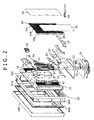
- FIG. 2 shows in exploded perspective components of the crystal display panel device according to an embodiment of the present invention.
- the outer frame 100 includes an outer frame upper side plate, an outer frame lower side plate, an outer frame left side plate, and an outer frame right side plate which are formed as aluminum extrusions, for example, and interfitted at the corners.
- the transparent upper side plate 210, the transparent lower side plate 220, the transparent left side plate 230, and the transparent right side plate 240, shown in FIG. 1, are applied by double-sided adhesive tapes to the respective inner sides of the outer frame upper side plate, the outer frame lower side plate, the outer frame left side plate, and the outer frame right side plate.
- Holders having mounting lugs on their inner sides are applied by double-sided adhesive tapes to the respective inner sides of the transparent upper side plate 210, the transparent lower side plate 220, the transparent left side plate 230, and the transparent right side plate 240.
- the outer frame 100 to which the holders, the transparent upper side plate 210, the transparent lower side plate 220, the transparent left side plate 230, and the transparent right side plate 240 are applied, is mounted on an inner frame 900 by the lugs that are fastened to the inner frame 900 by screws.
- the inner frame 900 is integrally molded of plastics.
- the liquid crystal display panel 20 is mounted in the inner frame 900, and the front mask 890 is mounted on a front side of the inner frame 900.
- a left heat radiating plate 31 and a right heat radiating plate 32 are mounted on the rear side of the liquid crystal display panel 20 respectively in left and right positions thereon.
- Each of the left heat radiating plate 31 and the right heat radiating plate 32 has a plurality of vertically extending fins that are spaced horizontally.
- the left heat radiating plate 31 and the right heat radiating plate 32 have vertically extending supports 31a, 32a, respectively, at their ends closer to the center of the rear side of the liquid crystal display panel 20, i.e., at the right end of the left heat radiating plate 31 and the left end of the right heat radiating plate 32, respectively.
- the supports 31a, 32a are higher than the fins.
- the left heat radiating plate 31 and the right heat radiating plate 32 are of a substantially L-shaped cross section, and are in the form of aluminum extrusions having identical cross-sectional shapes, for example.
- left heat radiating plate 31 and the right heat radiating plate 32 have the integrally formed supports 31a, 32a, they function as stiffening members having the mechanical strength of L-shaped angles, as a whole.
- Fans 41, 42 are mounted on the respective rear surfaces of the left heat radiating plate 31 and the right heat radiating plate 32.
- two fans 41 and two fans 42 are illustrated.
- One of the two fans 41 is shown as a mounted fan 41 and the other as a fan 41 prior to being mounted.
- one of the two fans 41 is shown as a mounted fan 41 and the other as a fan 42 prior to being mounted.
- the stand 51 has stand posts 52 combined with respective stand holders 53.
- the stand 51 is attached to the rear side of the liquid crystal display panel 20 by the stand holders 53.
- a circuit assembly (circuit board) 47 including a power supply circuit and a driver circuit is mounted on the rear side of the liquid crystal display panel 20 between the support 31a formed on the right end of the left heat radiating plate 31 and the support 32a formed on the left end of the right heat radiating plate 32.
- a central rear cover 33 which covers the circuit assembly 47 is also mounted on the rear side of the liquid crystal display panel 20 between the left heat radiating plate 31 and the right heat radiating plate 32 at a position behind the left heat radiating plate 31 and the right heat radiating plate 32.
- the central rear cover 33 includes a plurality of vertically extending fins that are spaced horizontally, as with the left heat radiating plate 31 and the right heat radiating plate 32, and is formed as aluminum extrusions, for example.
- the central rear cover 33 includes four cover members 33a, 33b, 33c, 33d that are horizontally joined by joints 34a, 34b, 34c.
- the central rear cover 33 is mounted on a stay 61 in an upper position on the rear side of the liquid crystal display panel 20 by screws 66 shown in FIG. 3 and a stay 63 in a lower position on the rear side of the liquid crystal display panel 20 by screws 66 shown in FIG. 3, in covering relation to the circuit assembly 47.
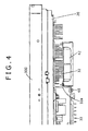
- FIG. 4 shows a right mounting structure on the rear side of the liquid crystal display panel 20.
- the central rear cover 33 has a right end fastened by screws 65 to the support 32a on the left end of the right heat radiating plate 32.
- the central rear cover 33 has a left end fastened by screws 65 (see FIG. 3) to the support 31a on the right end of the left heat radiating plate 31.
- a connector bracket 37 is mounted on a lower side of the central rear cover 33.
- the connector bracket 37 has a lower window 38 into which connector plugs 49 are inserted for supplying electric power and signals to the circuit assembly 47.
- a left rear cover 35 and a right rear cover 36 are mounted on the rear side of the liquid crystal display panel 20 in covering relation to the left heat radiating plate 31 and the right heat radiating plate 32, respectively.
- the left rear cover 35 and the right rear cover 36 lie substantially flush with the central rear cover 33.
- the left rear cover 35 and the right rear cover 36 are formed as flat plastic moldings.
- the left rear cover 35 and the right rear cover 36 are fastened to the inner frame 900 and the central rear cover 33 by screws 67.
- the left heat radiating plate 31, the right heat radiating plate 32, and the central rear cover 33 are mounted on the rear side of the liquid crystal display panel 20, and the left heat radiating plate 31 and the right heat radiating plate 32 function as stiffening members having the mechanical strength of L-shaped angles and are of a substantially L-shaped cross section, the left heat radiating plate 31 and the right heat radiating plate 32 having the vertically extending supports 31a, 32a near the center of the rear side of the liquid crystal display panel 20.
- the central rear cover 33 extends and is secured in place between the supports 31a, 32a, which confront each other, of the left heat radiating plate 31 and the right heat radiating plate 32, the mechanical strength of the liquid crystal display panel 20 is sufficiently increased, and the rigidity of the liquid crystal display panel device is also sufficiently increased.
- the left heat radiating plate 31 As the left heat radiating plate 31, the right heat radiating plate 32, and the central rear cover 33, each having fins, extend substantially fully over the rear side of the liquid crystal display panel 20, heat generated in the liquid crystal display panel device is reliably and effectively discharged out of the liquid crystal display panel device.
- heat generated by the liquid crystal display panel 20 is reduced by the left heat radiating plate 31 and the right heat radiating plate 32, and transferred to the central rear cover 33, which radiates the heat through its fins.
- the central rear cover 33 having fins and formed as an aluminum extrusion, for example, extends over a wide central area of the rear side of the liquid crystal display panel 20, the rear side of the liquid crystal display panel device provides excellent designability for a better functional appearance.
- the left rear cover 35 and the right rear cover 36 which lie substantially flush with the central rear cover 33 and are disposed one on each side of the central rear cover 33 provide an improved appearance.
- the central rear cover 33, the left rear cover 35 and the right rear cover 36 are made of one material such as aluminum and coated in one color, then they provide excellent designability.
- a display panel device may be constructed as a wall-mounted display panel device.
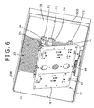
- FIG. 6 shows a wall-mounted liquid crystal display panel device 5.
- the wall-mounted liquid crystal display panel device 5 includes a liquid crystal display panel 20 whose rear structure is essentially identical to the rear structure shown in FIGS. 1 through 5 except that it does not have a stand and related parts. Therefore, those parts of the wall-mounted liquid crystal display panel device 5 which are identical to those of the self-standing liquid crystal display panel device are denoted by identical reference numerals and will not be described in detail below.
- the wall-mounted liquid crystal display panel device 5 has a wall-mounting unit 70 on the rear side thereof.
- the wall-mounting unit 70 includes mounting bars 71, 72 and 73, each in the form of a pipe having a rectangular cross section, extending horizontally between the left rear cover 35 and the right rear cover 36 on the rear side of the liquid crystal display panel device 5 and fastened to the central rear cover 33 through the left rear cover 35 and the right rear cover 36 by screws 76.
- the mounting bars 71, 72 and 73 are coupled to a mounting plate 74 fixed to a wall 9 by a collapsible link mechanism 75.
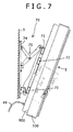
- the collapsible link mechanism 75 allows the liquid crystal display panel device 5 to be angularly moved between a tilted position in which the liquid crystal display panel device 5 is tilted away from the wall 9 as shown in FIG. 7 and a parallel position in which the liquid crystal display panel device 5 is parallel to the wall 9.
- the display panel device has been described as a liquid crystal display panel device. However, the principles of the present invention are also applicable to any of various other display panel devices, such as a plasma display panel device.
- left and right heat radiating plates are mounted on the rear side of a liquid crystal display panel in respective left and right positions thereon.
- the left and right heat radiating plates are of a substantially L-shaped cross section including a plurality of fins and respective supports near the center of the rear side of the liquid crystal display panel.
- a central rear cover has a plurality of fins and has left and right ends fixedly mounted respectively on the supports of the left and right heat radiating plates in covering relation to a circuit assembly on the rear side of the liquid crystal display panel.
- Left and right rear covers are mounted respectively on rear sides of the left and right heat radiating plates and lie substantially flush with the central rear cover.
Landscapes
- Physics & Mathematics (AREA)
- Engineering & Computer Science (AREA)
- Nonlinear Science (AREA)
- General Physics & Mathematics (AREA)
- General Engineering & Computer Science (AREA)
- Theoretical Computer Science (AREA)
- Mathematical Physics (AREA)
- Chemical & Material Sciences (AREA)
- Crystallography & Structural Chemistry (AREA)
- Optics & Photonics (AREA)
- Computer Hardware Design (AREA)
- Human Computer Interaction (AREA)
- Thermal Sciences (AREA)
- Microelectronics & Electronic Packaging (AREA)
- Mechanical Engineering (AREA)
- Devices For Indicating Variable Information By Combining Individual Elements (AREA)
- Liquid Crystal (AREA)
Abstract
Description
- The present invention relates to a display panel device such as a liquid crystal display panel device or the like.
- Display panel devices such as liquid crystal display panel devices or the like which have large screen sizes are required to have increased display panel strength for higher rigidity and also to discharge heat generated in the devices reliably and effectively out of the devices.
- Japanese Patent Laid-open No. 2003-150076 discloses a liquid crystal display panel device having a liquid crystal display panel that is fixed to a front cover by left, right, and central stays extending in the transverse direction of the front cover and pressing peripheral edges of the liquid crystal display panel. The disclosed liquid crystal display panel device also has a planar rear cover mounted on the rear side of the liquid crystal display panel.
- However, the liquid crystal display panel device of the above construction fails to provide sufficiently increased display panel strength for sufficiently high rigidity and also fails to discharge heat generated in the device reliably and effectively out of the device.
- Embodiments of the present invention seek to provide a liquid crystal display panel device of simple structure which has increased display panel strength for higher rigidity and which is capable of discharging heat generated in the device reliably and effectively out of the device.
- According to one aspect of the present invention, there is provided a display panel device including a display panel having a rear side, a left heat radiating plate mounted on the rear side of the display panel in a left position thereof, the left heat radiating plate having a substantially L-shaped cross section including a vertically extending support disposed on an end thereof close to a center of the rear side, a right heat radiating plate mounted on the rear side of the display panel in a right position thereof, the right heat radiating plate having a substantially L-shaped cross section including a vertically extending support disposed on an end thereof close to the center of the rear side in confronting relation to the support of the left heat radiating plate, a central rear cover having left and right ends fixedly mounted respectively on the supports of the left heat radiating plate and the right heat radiating plate, a left rear cover mounted on a rear side of the left heat radiating plate, and a right rear cover mounted on a rear side of the right heat radiating plate.
- With the above arrangement, the left heat radiating plate, the right heat radiating plate, and the central rear cover are mounted on the rear side of the display panel, and the left heat radiating plate and the right heat radiating plate function as stiffening members having the mechanical strength of L-shaped angles and are of a substantially L-shaped cross section, the left heat radiating plate and the right heat radiating plate having the vertically extending supports near the center of the rear side of the display panel. Since the central rear cover extends and is secured in place between the supports, which confront each other, of the left heat radiating plate and the right heat radiating plate, the mechanical strength of the display panel is sufficiently increased, and the rigidity of the display panel device is also sufficiently increased.
- As the left heat radiating plate and the right heat radiating plate cover left and right areas of the rear side of the display panel and have their supports joined to the central rear cover, heat generated in the display panel device is reliably and effectively radiated out of the display panel device.
- If the central rear cover includes a heat radiating plate having a plurality of fins, then the central rear cover can easily be formed as an aluminum extrusion or the like. Since the central rear cover with the fins extend over a wide central area of the rear side of the display panel, the rear side of the display panel device provides excellent designability for better functional appearance.
- Further particular and preferred aspects of the present invention are set out in the accompanying independent and dependent claims. Features of the dependent claims may be combined with features of the independent claims as appropriate, and in combinations other than those explicitly set out in the claims.
- The present invention will be described further, by way of example only, with reference to preferred embodiments thereof as illustrated in the accompanying drawings, in which:
- FIG. 1 is a front elevational view of a liquid crystal display panel device according to an embodiment of the present invention, which is used as a self-standing liquid crystal display panel device;
- FIG. 2 is an exploded perspective view of components of the crystal display panel device according to an embodiment of the present invention;
- FIG. 3 is a perspective view of a central rear cover of the crystal display panel device according to an embodiment of the present invention;
- FIG. 4 is a fragmentary plan view of the crystal display panel device according to an embodiment of the present invention;
- FIG. 5 is a perspective view, partly cut away, showing a rear structure of the crystal display panel device according to an embodiment of the present invention;
- FIG. 6 is a rear view of the crystal display panel device according to an embodiment of the present invention, which is used as a wall-mounted crystal display panel device; and
- FIG. 7 is a side elevational view of the wall-mounted crystal display panel device shown in FIG. 6.
- As shown in FIG. 1, a display panel device according to an embodiment of the present invention, which is constructed as a self-standing liquid crystal display panel device, includes a
frame assembly 10 and a liquidcrystal display panel 20 which are mounted on astand 51. - The
frame assembly 10 includes anouter frame 100, an inner frame (cabinet) that is omitted from illustration in FIG. 1, a transparentupper side plate 210, a transparentlower side plate 220, a transparentleft side plate 230, and a transparentright side plate 240 which are interposed between theouter frame 100 and the inner frame. Theouter frame 100 has upper left, upper right, lower left, and lower right corners combined withrespective corner covers - The transparent
upper side plate 210, the transparentlower side plate 220, the transparentleft side plate 230, and the transparentright side plate 240 serve to create a floating effect which makes the display screen of the liquidcrystal display panel 20 look floating in the air by making a wall behind the liquid crystal display panel device visible through the transparentupper side plate 210, the transparentlower side plate 220, the transparentleft side plate 230, and the transparentright side plate 240. - Each of the transparent
upper side plate 210, the transparentlower side plate 220, the transparentleft side plate 230, and the transparentright side plate 240 is formed as an acrylic plate or a polycarbonate plate, and has a thickness of about 10 mm in the vertical or horizontal direction and a width of at least about several cm along the depth, i.e., in the front-to-rear direction. Therefore, the width is greater than the thickness. - The liquid
crystal display panel 20 is mounted in the inner frame, and has a liquid crystal display unit, a backlight, and a circuit and a power supply for energizing the liquid crystal display unit and the backlight. The liquid crystal display panel device has left and right speakers disposed within the inner frame. - The display screen of the liquid
crystal display panel 20 has peripheral edges spaced inwardly from the inner edges of the transparentupper side plate 210, the transparentlower side plate 220, the transparentleft side plate 230, and the transparentright side plate 240. The space between the peripheral edges of the display screen and the inner edges of theside plates front mask 890 for concealing an inner structure of the liquid crystal display panel device. - The
front mask 890 has a number of small circular holes (not shown) defined in each of the areas thereof which are aligned with the respective left and right speakers. - In the description which follows, the terms "vertical", "upper", "lower", "horizontal", "left", and "right", etc. are used with respect to the display screen of the liquid
crystal display panel 20 as shown in FIG. 1, and the term "depth" is used to represent a direction normal to the display screen, i.e., the sheet of FIG. 1. The terms "inward", "inner", "outward", and "outer", etc. are used with respect to the geometric center of the display screen. The terms "forward" and "front" are used to represent a direction toward the viewer of FIG. 1, and the terms "rearward" and "rear" are used to represent a direction away from the viewer of FIG. 1. - FIG. 2 shows in exploded perspective components of the crystal display panel device according to an embodiment of the present invention. The
outer frame 100 includes an outer frame upper side plate, an outer frame lower side plate, an outer frame left side plate, and an outer frame right side plate which are formed as aluminum extrusions, for example, and interfitted at the corners. - The transparent
upper side plate 210, the transparentlower side plate 220, the transparentleft side plate 230, and the transparentright side plate 240, shown in FIG. 1, are applied by double-sided adhesive tapes to the respective inner sides of the outer frame upper side plate, the outer frame lower side plate, the outer frame left side plate, and the outer frame right side plate. - Holders having mounting lugs on their inner sides are applied by double-sided adhesive tapes to the respective inner sides of the transparent
upper side plate 210, the transparentlower side plate 220, the transparentleft side plate 230, and the transparentright side plate 240. - The
outer frame 100, to which the holders, the transparentupper side plate 210, the transparentlower side plate 220, the transparentleft side plate 230, and the transparentright side plate 240 are applied, is mounted on aninner frame 900 by the lugs that are fastened to theinner frame 900 by screws. Theinner frame 900 is integrally molded of plastics. - The liquid
crystal display panel 20 is mounted in theinner frame 900, and thefront mask 890 is mounted on a front side of theinner frame 900. - A left
heat radiating plate 31 and a rightheat radiating plate 32 are mounted on the rear side of the liquidcrystal display panel 20 respectively in left and right positions thereon. Each of the left heatradiating plate 31 and the right heatradiating plate 32 has a plurality of vertically extending fins that are spaced horizontally. The leftheat radiating plate 31 and the right heatradiating plate 32 have vertically extending supports 31a, 32a, respectively, at their ends closer to the center of the rear side of the liquidcrystal display panel 20, i.e., at the right end of the leftheat radiating plate 31 and the left end of the rightheat radiating plate 32, respectively. Thesupports heat radiating plate 31 and the rightheat radiating plate 32 are of a substantially L-shaped cross section, and are in the form of aluminum extrusions having identical cross-sectional shapes, for example. - Since the left
heat radiating plate 31 and the right heatradiating plate 32 have the integrally formed supports 31a, 32a, they function as stiffening members having the mechanical strength of L-shaped angles, as a whole. -
Fans heat radiating plate 31 and the rightheat radiating plate 32. In FIG. 2, twofans 41 and twofans 42 are illustrated. One of the twofans 41 is shown as a mountedfan 41 and the other as afan 41 prior to being mounted. Similarly, one of the twofans 41 is shown as a mountedfan 41 and the other as afan 42 prior to being mounted. - The
stand 51 has standposts 52 combined withrespective stand holders 53. Thestand 51 is attached to the rear side of the liquidcrystal display panel 20 by thestand holders 53. - A circuit assembly (circuit board) 47 including a power supply circuit and a driver circuit is mounted on the rear side of the liquid
crystal display panel 20 between thesupport 31a formed on the right end of the leftheat radiating plate 31 and thesupport 32a formed on the left end of the rightheat radiating plate 32. - A central
rear cover 33 which covers thecircuit assembly 47 is also mounted on the rear side of the liquidcrystal display panel 20 between the leftheat radiating plate 31 and the rightheat radiating plate 32 at a position behind the leftheat radiating plate 31 and the rightheat radiating plate 32. - The central
rear cover 33 includes a plurality of vertically extending fins that are spaced horizontally, as with the left heatradiating plate 31 and the rightheat radiating plate 32, and is formed as aluminum extrusions, for example. - It is difficult to form the central
rear cover 33 as a single extrusion having a large horizontal width. Actually, as also shown in FIG. 3, the centralrear cover 33 includes fourcover members joints - The central
rear cover 33 is mounted on astay 61 in an upper position on the rear side of the liquidcrystal display panel 20 byscrews 66 shown in FIG. 3 and astay 63 in a lower position on the rear side of the liquidcrystal display panel 20 byscrews 66 shown in FIG. 3, in covering relation to thecircuit assembly 47. - FIG. 4 shows a right mounting structure on the rear side of the liquid
crystal display panel 20. The centralrear cover 33 has a right end fastened byscrews 65 to thesupport 32a on the left end of the rightheat radiating plate 32. The centralrear cover 33 has a left end fastened by screws 65 (see FIG. 3) to thesupport 31a on the right end of the leftheat radiating plate 31. - As shown in FIG. 5, a
connector bracket 37 is mounted on a lower side of the centralrear cover 33. Theconnector bracket 37 has alower window 38 into which connector plugs 49 are inserted for supplying electric power and signals to thecircuit assembly 47. - A left
rear cover 35 and a rightrear cover 36 are mounted on the rear side of the liquidcrystal display panel 20 in covering relation to the leftheat radiating plate 31 and the rightheat radiating plate 32, respectively. The leftrear cover 35 and the rightrear cover 36 lie substantially flush with the centralrear cover 33. Unlike the centralrear cover 33, the leftrear cover 35 and the rightrear cover 36 are formed as flat plastic moldings. The leftrear cover 35 and the rightrear cover 36 are fastened to theinner frame 900 and the centralrear cover 33 byscrews 67. - According to the rear structure of the liquid
crystal display panel 20 as described above, the leftheat radiating plate 31, the rightheat radiating plate 32, and the centralrear cover 33 are mounted on the rear side of the liquidcrystal display panel 20, and the leftheat radiating plate 31 and the rightheat radiating plate 32 function as stiffening members having the mechanical strength of L-shaped angles and are of a substantially L-shaped cross section, the leftheat radiating plate 31 and the rightheat radiating plate 32 having the vertically extendingsupports crystal display panel 20. Since the centralrear cover 33 extends and is secured in place between thesupports heat radiating plate 31 and the rightheat radiating plate 32, the mechanical strength of the liquidcrystal display panel 20 is sufficiently increased, and the rigidity of the liquid crystal display panel device is also sufficiently increased. - As the left
heat radiating plate 31, the rightheat radiating plate 32, and the centralrear cover 33, each having fins, extend substantially fully over the rear side of the liquidcrystal display panel 20, heat generated in the liquid crystal display panel device is reliably and effectively discharged out of the liquid crystal display panel device. - Particularly, heat generated by the liquid
crystal display panel 20 is reduced by the leftheat radiating plate 31 and the rightheat radiating plate 32, and transferred to the centralrear cover 33, which radiates the heat through its fins. - Because the central
rear cover 33 having fins and formed as an aluminum extrusion, for example, extends over a wide central area of the rear side of the liquidcrystal display panel 20, the rear side of the liquid crystal display panel device provides excellent designability for a better functional appearance. The leftrear cover 35 and the rightrear cover 36 which lie substantially flush with the centralrear cover 33 and are disposed one on each side of the centralrear cover 33 provide an improved appearance. - If the central
rear cover 33, the leftrear cover 35 and the rightrear cover 36 are made of one material such as aluminum and coated in one color, then they provide excellent designability. - A display panel device according to an embodiment of the present invention may be constructed as a wall-mounted display panel device.
- FIG. 6 shows a wall-mounted liquid crystal
display panel device 5. The wall-mounted liquid crystaldisplay panel device 5 includes a liquidcrystal display panel 20 whose rear structure is essentially identical to the rear structure shown in FIGS. 1 through 5 except that it does not have a stand and related parts. Therefore, those parts of the wall-mounted liquid crystaldisplay panel device 5 which are identical to those of the self-standing liquid crystal display panel device are denoted by identical reference numerals and will not be described in detail below. - As shown in FIG. 7, the wall-mounted liquid crystal
display panel device 5 has a wall-mountingunit 70 on the rear side thereof. - The wall-mounting
unit 70 includes mountingbars rear cover 35 and the rightrear cover 36 on the rear side of the liquid crystaldisplay panel device 5 and fastened to the centralrear cover 33 through the leftrear cover 35 and the rightrear cover 36 byscrews 76. The mounting bars 71, 72 and 73 are coupled to a mountingplate 74 fixed to awall 9 by acollapsible link mechanism 75. - The
collapsible link mechanism 75 allows the liquid crystaldisplay panel device 5 to be angularly moved between a tilted position in which the liquid crystaldisplay panel device 5 is tilted away from thewall 9 as shown in FIG. 7 and a parallel position in which the liquid crystaldisplay panel device 5 is parallel to thewall 9. - The display panel device according to an embodiment of the present invention has been described as a liquid crystal display panel device. However, the principles of the present invention are also applicable to any of various other display panel devices, such as a plasma display panel device.
- In embodiments, left and right heat radiating plates are mounted on the rear side of a liquid crystal display panel in respective left and right positions thereon. The left and right heat radiating plates are of a substantially L-shaped cross section including a plurality of fins and respective supports near the center of the rear side of the liquid crystal display panel. A central rear cover has a plurality of fins and has left and right ends fixedly mounted respectively on the supports of the left and right heat radiating plates in covering relation to a circuit assembly on the rear side of the liquid crystal display panel. Left and right rear covers are mounted respectively on rear sides of the left and right heat radiating plates and lie substantially flush with the central rear cover.
- Although particular embodiments have been described herein, it will be appreciated that the invention is not limited thereto and that many modifications and additions thereto may be made within the scope of the invention. For example, various combinations of the features of the following dependent claims can be made with the features of the independent claims without departing from the scope of the present invention.
Claims (5)
- A display panel device comprising:a display panel having a rear side;a left heat radiating plate mounted on the rear side of said display panel in a left position thereof, said left heat radiating plate having a substantially L-shaped cross section comprising a vertically extending support disposed on an end thereof close to a center of said rear side;a right heat radiating plate mounted on the rear side of said display panel in a right position thereof, said right heat radiating plate having a substantially L-shaped cross section comprising a vertically extending support disposed on an end thereof close to the center of said rear side in confronting relation to the support of said left heat radiating plate;a central rear cover having left and right ends fixedly mounted respectively on the supports of said left heat radiating plate and said right heat radiating plate;a left rear cover mounted on a rear side of said left heat radiating plate; anda right rear cover mounted on a rear side of said right heat radiating plate.
- The display panel device according to claim 1, wherein said central rear cover has a plurality of vertically extending fins which are spaced horizontally.
- The display panel device according to claim 2, wherein said central rear cover comprises an aluminum extrusion.
- The display panel device according to claim 1, wherein said display panel comprises a liquid crystal display panel.
- The display panel device according to claim 1, further comprising:a wall-mounting unit mounted on said central rear cover near the left and right ends thereof which are fixedly mounted respectively on the supports of said left heat radiating plate and said right heat radiating plate.
Applications Claiming Priority (2)
| Application Number | Priority Date | Filing Date | Title |
|---|---|---|---|
| JP2004205322 | 2004-07-12 | ||
| JP2005159446A JP4221605B2 (en) | 2004-07-12 | 2005-05-31 | Display panel device |
Publications (2)
| Publication Number | Publication Date |
|---|---|
| EP1619539A1 true EP1619539A1 (en) | 2006-01-25 |
| EP1619539B1 EP1619539B1 (en) | 2008-03-26 |
Family
ID=35057082
Family Applications (1)
| Application Number | Title | Priority Date | Filing Date |
|---|---|---|---|
| EP05254292A Expired - Lifetime EP1619539B1 (en) | 2004-07-12 | 2005-07-08 | Display panel device with improved rigidity |
Country Status (5)
| Country | Link |
|---|---|
| US (1) | US7269023B2 (en) |
| EP (1) | EP1619539B1 (en) |
| JP (1) | JP4221605B2 (en) |
| KR (1) | KR101066145B1 (en) |
| DE (1) | DE602005005566T2 (en) |
Cited By (1)
| Publication number | Priority date | Publication date | Assignee | Title |
|---|---|---|---|---|
| EP2592525A3 (en) * | 2011-11-11 | 2015-01-28 | MEKRA Lang GmbH & Co. KG | Monitor and back panel for monitor |
Families Citing this family (58)
| Publication number | Priority date | Publication date | Assignee | Title |
|---|---|---|---|---|
| KR20060027124A (en) * | 2004-09-22 | 2006-03-27 | 삼성에스디아이 주식회사 | Plasma display module having a filter film and plasma display device comprising the same |
| KR100670273B1 (en) * | 2005-01-18 | 2007-01-16 | 삼성에스디아이 주식회사 | Heat dissipation assembly for plasma display device and plasma display device having same |
| TWM278930U (en) * | 2005-04-29 | 2005-10-21 | Innolux Display Corp | A supporting bracket and liquid crystal display device using the same |
| US20070086167A1 (en) * | 2005-10-18 | 2007-04-19 | Chi Lin Technology Co., Ltd. | Heat sink having speed-up heat-dissipating structure |
| JP4572828B2 (en) * | 2005-12-08 | 2010-11-04 | ソニー株式会社 | Image display device |
| WO2007097592A1 (en) * | 2006-02-23 | 2007-08-30 | Lg Chem, Ltd. | Display apparatus, heat conductive adhesive sheet for display apparatus, and process for preparing the same |
| US7733633B2 (en) * | 2006-03-01 | 2010-06-08 | Pdi Communication Systems, Inc. | Video display unit support bracket |
| TWM307949U (en) * | 2006-09-22 | 2007-03-11 | Forcecon Technology Co Ltd | Heat-dissipating module structure with heat-conductive panel |
| JP5259110B2 (en) * | 2007-03-27 | 2013-08-07 | 三菱電機株式会社 | Display device |
| KR101435801B1 (en) * | 2007-08-30 | 2014-08-29 | 엘지전자 주식회사 | Display device |
| US8854595B2 (en) | 2008-03-03 | 2014-10-07 | Manufacturing Resources International, Inc. | Constricted convection cooling system for an electronic display |
| US12185512B2 (en) | 2007-11-16 | 2024-12-31 | Manufacturing Resources International, Inc. | Electronic display assembly with thermal management |
| US8654302B2 (en) | 2008-03-03 | 2014-02-18 | Manufacturing Resources International, Inc. | Heat exchanger for an electronic display |
| US8497972B2 (en) | 2009-11-13 | 2013-07-30 | Manufacturing Resources International, Inc. | Thermal plate with optional cooling loop in electronic display |
| US8693185B2 (en) | 2008-03-26 | 2014-04-08 | Manufacturing Resources International, Inc. | System and method for maintaining a consistent temperature gradient across an electronic display |
| EP2110734B1 (en) * | 2008-04-16 | 2011-01-26 | Siemens Aktiengesellschaft | Support frame for holding an operating panel |
| US8167253B2 (en) * | 2008-06-02 | 2012-05-01 | Sony Corporation | Flat panel TV stand providing floating appearance |
| TWI375505B (en) * | 2008-10-24 | 2012-10-21 | Wistron Corp | Frame structure and display apparatus using the same |
| US10827656B2 (en) | 2008-12-18 | 2020-11-03 | Manufacturing Resources International, Inc. | System for cooling an electronic image assembly with circulating gas and ambient gas |
| US8749749B2 (en) | 2008-12-18 | 2014-06-10 | Manufacturing Resources International, Inc. | System for cooling an electronic image assembly with manifolds and ambient gas |
| TWI396152B (en) * | 2009-06-26 | 2013-05-11 | Au Optronics Corp | Display device |
| CN102375514A (en) * | 2010-08-19 | 2012-03-14 | 鸿富锦精密工业(深圳)有限公司 | Electronic device |
| CN102566719A (en) * | 2010-12-30 | 2012-07-11 | 鸿富锦精密工业(深圳)有限公司 | Electronic device |
| US9036338B2 (en) * | 2012-04-16 | 2015-05-19 | SmallHD, LLC | Support frame for high definition field monitor |
| KR101868077B1 (en) | 2012-10-16 | 2018-06-18 | 매뉴팩처링 리소시스 인터내셔널 인코포레이티드 | Back pan cooling assembly for electric display |
| US9648790B2 (en) | 2013-03-15 | 2017-05-09 | Manufacturing Resources International, Inc. | Heat exchanger assembly for an electronic display |
| US10524384B2 (en) | 2013-03-15 | 2019-12-31 | Manufacturing Resources International, Inc. | Cooling assembly for an electronic display |
| CA2917868A1 (en) | 2013-07-08 | 2015-01-15 | Manufacturing Resources International, Inc. | Figure eight closed loop cooling system for electronic display |
| KR102040612B1 (en) * | 2013-08-21 | 2019-11-05 | 엘지전자 주식회사 | Display device |
| ES2745563T3 (en) | 2014-03-11 | 2020-03-02 | Mri Inc | Hybrid back cover and mounting bracket for an electronic display |
| CA2947524C (en) | 2014-04-30 | 2018-04-03 | Manufacturing Resources International, Inc. | Back to back electronic display assembly |
| US9723765B2 (en) | 2015-02-17 | 2017-08-01 | Manufacturing Resources International, Inc. | Perimeter ventilation system for electronic display |
| JP6528137B2 (en) | 2015-03-19 | 2019-06-12 | パナソニックIpマネジメント株式会社 | Curved display device |
| US9857618B2 (en) * | 2015-05-18 | 2018-01-02 | Michael S. Barnes | Display enclosure with passive cooling system |
| CN104951010B (en) * | 2015-07-17 | 2019-03-08 | 成都阿普奇科技股份有限公司 | Combined Industrial Panel PC |
| EP3423886B1 (en) | 2016-03-04 | 2022-02-16 | Manufacturing Resources International, Inc. | Cooling system for double sided display assembly |
| JP6867205B2 (en) | 2017-03-22 | 2021-04-28 | シャープ株式会社 | Cover mounting structure and display device |
| US10485113B2 (en) | 2017-04-27 | 2019-11-19 | Manufacturing Resources International, Inc. | Field serviceable and replaceable display |
| US10398066B2 (en) | 2017-04-27 | 2019-08-27 | Manufacturing Resources International, Inc. | System and method for preventing display bowing |
| US10559965B2 (en) | 2017-09-21 | 2020-02-11 | Manufacturing Resources International, Inc. | Display assembly having multiple charging ports |
| USD888054S1 (en) * | 2018-02-05 | 2020-06-23 | Dell Products L.P. | Monitor with integrated camera |
| US10602626B2 (en) | 2018-07-30 | 2020-03-24 | Manufacturing Resources International, Inc. | Housing assembly for an integrated display unit |
| US11096317B2 (en) | 2019-02-26 | 2021-08-17 | Manufacturing Resources International, Inc. | Display assembly with loopback cooling |
| US10795413B1 (en) | 2019-04-03 | 2020-10-06 | Manufacturing Resources International, Inc. | Electronic display assembly with a channel for ambient air in an access panel |
| US11477923B2 (en) | 2020-10-02 | 2022-10-18 | Manufacturing Resources International, Inc. | Field customizable airflow system for a communications box |
| US11778757B2 (en) | 2020-10-23 | 2023-10-03 | Manufacturing Resources International, Inc. | Display assemblies incorporating electric vehicle charging equipment |
| US11470749B2 (en) | 2020-10-23 | 2022-10-11 | Manufacturing Resources International, Inc. | Forced air cooling for display assemblies using centrifugal fans |
| US11966263B2 (en) | 2021-07-28 | 2024-04-23 | Manufacturing Resources International, Inc. | Display assemblies for providing compressive forces at electronic display layers |
| US12408312B2 (en) | 2021-07-28 | 2025-09-02 | Manufacturing Resources International, Inc. | Display assemblies with vents |
| US11919393B2 (en) | 2021-08-23 | 2024-03-05 | Manufacturing Resources International, Inc. | Display assemblies inducing relatively turbulent flow and integrating electric vehicle charging equipment |
| US11744054B2 (en) | 2021-08-23 | 2023-08-29 | Manufacturing Resources International, Inc. | Fan unit for providing improved airflow within display assemblies |
| US11762231B2 (en) | 2021-08-23 | 2023-09-19 | Manufacturing Resources International, Inc. | Display assemblies inducing turbulent flow |
| US11968813B2 (en) | 2021-11-23 | 2024-04-23 | Manufacturing Resources International, Inc. | Display assembly with divided interior space |
| GB2614748B (en) * | 2022-01-18 | 2024-10-09 | Amscreen Group Ltd | Cooling of electronic displays |
| US12010813B2 (en) | 2022-07-22 | 2024-06-11 | Manufacturing Resources International, Inc. | Self-contained electronic display assembly, mounting structure and methods for the same |
| US12072561B2 (en) | 2022-07-22 | 2024-08-27 | Manufacturing Resources International, Inc. | Self-contained electronic display assembly, mounting structure and methods for the same |
| US12035486B1 (en) | 2022-07-25 | 2024-07-09 | Manufacturing Resources International, Inc. | Electronic display assembly with fabric panel communications box |
| US12598727B2 (en) | 2024-01-09 | 2026-04-07 | Manufacturing Resources International, Inc. | Double sided display assembly with bi-directional flow through a common, partitioned heat exchanger |
Citations (5)
| Publication number | Priority date | Publication date | Assignee | Title |
|---|---|---|---|---|
| WO2000005620A1 (en) * | 1998-07-22 | 2000-02-03 | Silicon Graphics, Inc. | Monitor |
| US20020048152A1 (en) * | 2000-09-29 | 2002-04-25 | Ibm | IC heat radiation structure and display device |
| JP2003150076A (en) | 2001-11-08 | 2003-05-21 | Sony Corp | Display device |
| US20030095216A1 (en) * | 2000-03-15 | 2003-05-22 | Nec Corporation | Liquid crystal display and light source device used for the same |
| EP1382991A2 (en) * | 2002-07-16 | 2004-01-21 | Samsung Electronics Co., Ltd. | Display apparatus |
Family Cites Families (7)
| Publication number | Priority date | Publication date | Assignee | Title |
|---|---|---|---|---|
| US5971566A (en) * | 1996-07-23 | 1999-10-26 | Matsushita Electric Industrial Co., Ltd. | Plasma display device and its manufacturing method |
| JP3747306B2 (en) * | 1998-03-25 | 2006-02-22 | 株式会社日立プラズマパテントライセンシング | Plasma display device |
| TW393666B (en) * | 1998-06-15 | 2000-06-11 | Acer Display Tech Inc | A plasma display device having a heated airflow guiding groove |
| JP2001183987A (en) | 1999-12-27 | 2001-07-06 | Pioneer Electronic Corp | Cooling structure and display device using the same |
| JP2001337611A (en) | 2000-03-22 | 2001-12-07 | Furukawa Electric Co Ltd:The | Display frame |
| JP5042414B2 (en) * | 2001-04-24 | 2012-10-03 | 株式会社日立製作所 | Plasma display device |
| US7072179B1 (en) * | 2004-09-10 | 2006-07-04 | Micro Industries Corporation | Fanless computer with integrated display |
-
2005
- 2005-05-31 JP JP2005159446A patent/JP4221605B2/en not_active Expired - Fee Related
- 2005-07-07 KR KR1020050061348A patent/KR101066145B1/en not_active Expired - Fee Related
- 2005-07-08 DE DE602005005566T patent/DE602005005566T2/en not_active Expired - Lifetime
- 2005-07-08 EP EP05254292A patent/EP1619539B1/en not_active Expired - Lifetime
- 2005-07-11 US US11/177,386 patent/US7269023B2/en not_active Expired - Fee Related
Patent Citations (5)
| Publication number | Priority date | Publication date | Assignee | Title |
|---|---|---|---|---|
| WO2000005620A1 (en) * | 1998-07-22 | 2000-02-03 | Silicon Graphics, Inc. | Monitor |
| US20030095216A1 (en) * | 2000-03-15 | 2003-05-22 | Nec Corporation | Liquid crystal display and light source device used for the same |
| US20020048152A1 (en) * | 2000-09-29 | 2002-04-25 | Ibm | IC heat radiation structure and display device |
| JP2003150076A (en) | 2001-11-08 | 2003-05-21 | Sony Corp | Display device |
| EP1382991A2 (en) * | 2002-07-16 | 2004-01-21 | Samsung Electronics Co., Ltd. | Display apparatus |
Cited By (2)
| Publication number | Priority date | Publication date | Assignee | Title |
|---|---|---|---|---|
| EP2592525A3 (en) * | 2011-11-11 | 2015-01-28 | MEKRA Lang GmbH & Co. KG | Monitor and back panel for monitor |
| US9049804B2 (en) | 2011-11-11 | 2015-06-02 | Mekra Lang Gmbh & Co. Kg | Modular monitor enclosed in a housing with a novel rear panel |
Also Published As
| Publication number | Publication date |
|---|---|
| DE602005005566D1 (en) | 2008-05-08 |
| US20060018092A1 (en) | 2006-01-26 |
| US7269023B2 (en) | 2007-09-11 |
| KR101066145B1 (en) | 2011-09-20 |
| DE602005005566T2 (en) | 2009-04-30 |
| JP2006053529A (en) | 2006-02-23 |
| KR20060049937A (en) | 2006-05-19 |
| EP1619539B1 (en) | 2008-03-26 |
| JP4221605B2 (en) | 2009-02-12 |
Similar Documents
| Publication | Publication Date | Title |
|---|---|---|
| EP1619539B1 (en) | Display panel device with improved rigidity | |
| KR100441526B1 (en) | Plasma display device | |
| US6421231B1 (en) | Display unit and portable computer using the same | |
| EP1318675B1 (en) | Display apparatus | |
| US8098487B2 (en) | Display apparatus | |
| US10545360B2 (en) | Liquid crystal module assembly and display device including the same | |
| US6661473B1 (en) | Projection type television receiver, and manufacturing method thereof | |
| US9470379B2 (en) | Display apparatus | |
| JP2013218117A (en) | Display apparatus | |
| CN101277414A (en) | display device | |
| AU733859B2 (en) | Air conditioning unit | |
| KR100542520B1 (en) | Plasma display device | |
| JPH11146305A (en) | Flat panel display | |
| CN107317985A (en) | Liquid crystal TV set | |
| EP2257144A2 (en) | Cabinet and display apparatus | |
| EP1617280A2 (en) | Frame assembly and electronic device | |
| CN107272243A (en) | Liquid crystal display | |
| CN107302674A (en) | Liquid crystal TV set | |
| US20140132877A1 (en) | Liquid crystal display, and configuration thereof | |
| CN100381896C (en) | display panel device | |
| US20090059500A1 (en) | Plasma Display System | |
| CN1312644C (en) | Chassis base unit for plasma display device and plasma display device including the chassis base unit | |
| AU2009203020A1 (en) | Low temperature showcase | |
| CN214545228U (en) | Display device | |
| CN113227888A (en) | Display panel and display device |
Legal Events
| Date | Code | Title | Description |
|---|---|---|---|
| PUAI | Public reference made under article 153(3) epc to a published international application that has entered the european phase |
Free format text: ORIGINAL CODE: 0009012 |
|
| AK | Designated contracting states |
Kind code of ref document: A1 Designated state(s): AT BE BG CH CY CZ DE DK EE ES FI FR GB GR HU IE IS IT LI LT LU LV MC NL PL PT RO SE SI SK TR |
|
| AX | Request for extension of the european patent |
Extension state: AL BA HR MK YU |
|
| 17P | Request for examination filed |
Effective date: 20060707 |
|
| GRAP | Despatch of communication of intention to grant a patent |
Free format text: ORIGINAL CODE: EPIDOSNIGR1 |
|
| AKX | Designation fees paid |
Designated state(s): DE FR GB |
|
| GRAS | Grant fee paid |
Free format text: ORIGINAL CODE: EPIDOSNIGR3 |
|
| GRAA | (expected) grant |
Free format text: ORIGINAL CODE: 0009210 |
|
| AK | Designated contracting states |
Kind code of ref document: B1 Designated state(s): DE FR GB |
|
| REG | Reference to a national code |
Ref country code: GB Ref legal event code: FG4D |
|
| REF | Corresponds to: |
Ref document number: 602005005566 Country of ref document: DE Date of ref document: 20080508 Kind code of ref document: P |
|
| ET | Fr: translation filed | ||
| PLBE | No opposition filed within time limit |
Free format text: ORIGINAL CODE: 0009261 |
|
| STAA | Information on the status of an ep patent application or granted ep patent |
Free format text: STATUS: NO OPPOSITION FILED WITHIN TIME LIMIT |
|
| 26N | No opposition filed |
Effective date: 20081230 |
|
| REG | Reference to a national code |
Ref country code: GB Ref legal event code: 746 Effective date: 20091130 |
|
| PGFP | Annual fee paid to national office [announced via postgrant information from national office to epo] |
Ref country code: FR Payment date: 20110729 Year of fee payment: 7 |
|
| PGFP | Annual fee paid to national office [announced via postgrant information from national office to epo] |
Ref country code: DE Payment date: 20110722 Year of fee payment: 7 Ref country code: GB Payment date: 20110721 Year of fee payment: 7 |
|
| GBPC | Gb: european patent ceased through non-payment of renewal fee |
Effective date: 20120708 |
|
| REG | Reference to a national code |
Ref country code: FR Ref legal event code: ST Effective date: 20130329 |
|
| PG25 | Lapsed in a contracting state [announced via postgrant information from national office to epo] |
Ref country code: DE Free format text: LAPSE BECAUSE OF NON-PAYMENT OF DUE FEES Effective date: 20130201 Ref country code: GB Free format text: LAPSE BECAUSE OF NON-PAYMENT OF DUE FEES Effective date: 20120708 Ref country code: FR Free format text: LAPSE BECAUSE OF NON-PAYMENT OF DUE FEES Effective date: 20120731 |
|
| REG | Reference to a national code |
Ref country code: DE Ref legal event code: R119 Ref document number: 602005005566 Country of ref document: DE Effective date: 20130201 |