EP1619381A1 - Fuel tank unit for a motor vehicle - Google Patents
Fuel tank unit for a motor vehicle Download PDFInfo
- Publication number
- EP1619381A1 EP1619381A1 EP20050015658 EP05015658A EP1619381A1 EP 1619381 A1 EP1619381 A1 EP 1619381A1 EP 20050015658 EP20050015658 EP 20050015658 EP 05015658 A EP05015658 A EP 05015658A EP 1619381 A1 EP1619381 A1 EP 1619381A1
- Authority
- EP
- European Patent Office
- Prior art keywords
- fuel tank
- fuel
- pump
- pad
- attached
- Prior art date
- Legal status (The legal status is an assumption and is not a legal conclusion. Google has not performed a legal analysis and makes no representation as to the accuracy of the status listed.)
- Withdrawn
Links
Images


Classifications
-
- F—MECHANICAL ENGINEERING; LIGHTING; HEATING; WEAPONS; BLASTING
- F02—COMBUSTION ENGINES; HOT-GAS OR COMBUSTION-PRODUCT ENGINE PLANTS
- F02M—SUPPLYING COMBUSTION ENGINES IN GENERAL WITH COMBUSTIBLE MIXTURES OR CONSTITUENTS THEREOF
- F02M37/00—Apparatus or systems for feeding liquid fuel from storage containers to carburettors or fuel-injection apparatus; Arrangements for purifying liquid fuel specially adapted for, or arranged on, internal-combustion engines
- F02M37/04—Feeding by means of driven pumps
- F02M37/08—Feeding by means of driven pumps electrically driven
- F02M37/10—Feeding by means of driven pumps electrically driven submerged in fuel, e.g. in reservoir
- F02M37/103—Mounting pumps on fuel tanks
-
- F—MECHANICAL ENGINEERING; LIGHTING; HEATING; WEAPONS; BLASTING
- F04—POSITIVE - DISPLACEMENT MACHINES FOR LIQUIDS; PUMPS FOR LIQUIDS OR ELASTIC FLUIDS
- F04D—NON-POSITIVE-DISPLACEMENT PUMPS
- F04D13/00—Pumping installations or systems
- F04D13/02—Units comprising pumps and their driving means
- F04D13/06—Units comprising pumps and their driving means the pump being electrically driven
- F04D13/0666—Units comprising pumps and their driving means the pump being electrically driven the motor being of the plane gap type
-
- F—MECHANICAL ENGINEERING; LIGHTING; HEATING; WEAPONS; BLASTING
- F04—POSITIVE - DISPLACEMENT MACHINES FOR LIQUIDS; PUMPS FOR LIQUIDS OR ELASTIC FLUIDS
- F04D—NON-POSITIVE-DISPLACEMENT PUMPS
- F04D5/00—Pumps with circumferential or transverse flow
- F04D5/002—Regenerative pumps
-
- B—PERFORMING OPERATIONS; TRANSPORTING
- B60—VEHICLES IN GENERAL
- B60K—ARRANGEMENT OR MOUNTING OF PROPULSION UNITS OR OF TRANSMISSIONS IN VEHICLES; ARRANGEMENT OR MOUNTING OF PLURAL DIVERSE PRIME-MOVERS IN VEHICLES; AUXILIARY DRIVES FOR VEHICLES; INSTRUMENTATION OR DASHBOARDS FOR VEHICLES; ARRANGEMENTS IN CONNECTION WITH COOLING, AIR INTAKE, GAS EXHAUST OR FUEL SUPPLY OF PROPULSION UNITS IN VEHICLES
- B60K15/00—Arrangement in connection with fuel supply of combustion engines or other fuel consuming energy converters, e.g. fuel cells; Mounting or construction of fuel tanks
- B60K15/03—Fuel tanks
- B60K2015/03328—Arrangements or special measures related to fuel tanks or fuel handling
- B60K2015/03453—Arrangements or special measures related to fuel tanks or fuel handling for fixing or mounting parts of the fuel tank together
-
- Y—GENERAL TAGGING OF NEW TECHNOLOGICAL DEVELOPMENTS; GENERAL TAGGING OF CROSS-SECTIONAL TECHNOLOGIES SPANNING OVER SEVERAL SECTIONS OF THE IPC; TECHNICAL SUBJECTS COVERED BY FORMER USPC CROSS-REFERENCE ART COLLECTIONS [XRACs] AND DIGESTS
- Y10—TECHNICAL SUBJECTS COVERED BY FORMER USPC
- Y10T—TECHNICAL SUBJECTS COVERED BY FORMER US CLASSIFICATION
- Y10T137/00—Fluid handling
- Y10T137/8593—Systems
- Y10T137/85978—With pump
- Y10T137/86035—Combined with fluid receiver
- Y10T137/86043—Reserve or surge receiver
Definitions
- the present invention relates to a fuel tank unit having a fuel tank and a fuel pump, and more particularly to technology to attach the fuel pump to the fuel tank.
- Japanese Laid-open Patent Publication No. 5-305827 describes a fuel tank unit.
- This fuel tank unit comprises a fuel tank and a fuel pump disposed within the fuel tank.
- the fuel pump supplies fuel from the fuel tank to an internal combustion engine of a vehicle.
- the fuel pump is located at the bottom in the center of the fuel tank where the depth of the fuel is stable even when the level of the fuel in the fuel tank changes dramatically.
- the fuel pump is mounted on one end of a pump support member, and positioned at the center of the bottom of the fuel tank. The other end of the pump support member is attached to the lid on the top of the fuel tank.
- the lid of the fuel tank has a union and a connector protruding and facing outward, with a fuel supply line is connected to the union, and a wire harness which supplies electrical power to the fuel pump connected to the connector. Space is required above the lid in order to arrange the union, the connector, the fuel supply line, and the harness. Conventionally, with a construction where the lid is located above the fuel tank, the space above the fuel tank cannot be conserved. Accordingly, it is one object of the present teachings to provide a fuel tank unit which can conserve the space above the fuel tank.
- fuel tank unit may comprise a fuel tank, a fuel pump, and a pad.
- the fuel pump may be attached to the bottom of the inside of the fuel tank.
- the pad is preferably located between the fuel tank and the fuel pump.
- the pad is preferably made of resin material (e.g., plastic).
- the fuel tank may have a flat box shape exterior. Preferably, at least a part of the top circumferential edge of the outside of the fuel tank is beveled.
- the fuel tank may have a lid in the region where the edge has been beveled.
- the fuel pump may be located substantially in the center of the inside bottom of the fuel tank. The space above the fuel tank can be conserved by having the lid at the location where the edge on outside of the fuel tank has been beveled.
- the length of the pump support member must be longer than if the lid is located on the top surface of the fuel tank.
- a flat fuel tank enhances this tendency.
- the rigidity of the pump support member decreases as the length increases. If the rigidity of the pump support member is low, the fuel pump itself will vibrate strongly when operating. If the fuel pump vibrates strongly, the vibrations will be transferred to the vehicle through the pump support member and cause a large noise. Rashly increasing the rigidity of the pump support member is impractical because of the cost or the like.
- the fuel tank unit comprises a pad which is located between the fuel tank and the fuel pump.
- a pump support member which is attached to the lid and supports the fuel pump is not necessary. Therefore, there will not be a loud noise from the fuel pump caused by the low rigidity of the fuel pump member. Furthermore, the noise produced by the fuel pump can be reduced by the vibration absorbing effect of the pad.
- the fuel pump may have a substantially disc shaped impeller and a casing which rotatably accommodates the impeller.
- the pad may be formed as a sheet.
- the casing of the fuel pump may be attached to the top surface of the pad.
- the inside surface of the casing of the fuel pump may have a fuel intake opening.
- the fuel pump may be attached to the fuel tank by the attracting action of a magnetic located in the bottom of the fuel tank.
- a recess may be formed on one side of the fuel tank and pad.
- a protrusion may be formed on the other side of the fuel tank and pad.
- the pad may be attached to the fuel tank by press fitting the protrusion into the recess.
- a hook accepting unit may be formed on one side of the fuel tank and pad.
- a hook may be established on the other side of the fuel tank and pad.
- the pad may be attached to the fuel tank by hooking the hook into the hook accepting unit.
- the fuel tank may have a member for determining the position of the pad.
- the member may be formed in the bottom of the fuel tank. If the member is formed to position the pad in the bottom of the fuel tank, positioning will be simplified when the fuel pump is to be attached inside the fuel tank.
- the fuel tank unit of the present embodiment may be used in a motor vehicle.
- the fuel tank unit comprises a fuel pump 10 and a fuel tank 11.
- the fuel pump 10 supplies fuel to an engine of the motor vehicle.
- the fuel pump 10 is attached to the bottom 12 of the fuel tank 11.
- the fuel tank 11 may have a flat box shape.
- the fuel tank 11 may be made from resin material (e.g., plastic).
- the fuel pump 10 is preferably located in the center region of the fuel tank 11 where the change in the depth of the fuel is stable even if the level 13 of the fuel in the fuel tank 11 changes.
- the fuel tank 11 may comprise a fuel tank body 11a and a set plate (tank lid) 14.
- the fuel tank body 11 a has a flat box shaped exterior and is formed such that a part of the top circumferential edge is beveled. An opening 11b is formed on the beveled region.
- the set plate 14 is attached to the opening 11b.
- a union 15 and an electrical connector 16 are fixed to the set plate 14.
- the union 15 and the fuel pump 10 are connected together by a fuel hose 20.
- the electrical connector 16 and the fuel pump 10 are connected by a wire harness 21.
- the fuel which is drawn into the fuel pump 10 flows through the fuel hose 20 and the union 15 and is pumped out of the fuel tank 11.
- the fuel which is pumped out of the fuel tank 11 is supplied to the engine.
- the fuel pump 10 is provided electrical power from the outside through the connector 16 and the wire harness 21.
- the set plate was attached to the top surface of the fuel tank. Therefore, space above the fuel tank is required for the fuel hose which is externally connected through the union and the wire harness which is externally connected to the electrical connector. If the space above the fuel tank is used, the comfort of the vehicle will be hindered.
- the fuel tank 11 has a flat box shape and the set plate 14 is positioned at an angle in the region where part of the upper circumferential edge of the fuel tank has been beveled. Therefore, the fuel tank 11 of the present embodiment is flat and contributes to improved comfort in the vehicle by conserving the space above the fuel tank.
- the fuel pump 10 has a pump body 31.
- a pad 63 is attached to the bottom of the pump body 31.
- the pump body 31 is attached to the bottom 12 of the fuel tank 11 through the pad 63.
- the pump body 31 comprises a housing 30, a circuit section 32, and a pump section 43.
- the housing 30 has a substantially cylindrical shape on the bottom, and the circuit section 32 and the pump section 43 are accommodated by crimping the top edge inward.
- the housing 30 may be made of steel.
- the circuit section 32 comprises a circuit casing 33 and a circuit board 34.
- the circuit casing 33 has a discharge port 36 which opens facing upward.
- One end of the fuel hose 20 (shown in Fig. 1) is connected to the discharge port 36.
- a bead 36a extending in the circumferential direction is formed on the outside surface of the discharge port 36.
- the bead 36a is established in order to positively connect the fuel hose 20 to the discharge port 36, or in other words to prevent the fuel hose 20 from separating from the discharge port 36.
- a terminal 37 is established on the top surface of the circuit casing 33.
- One end of the wire harness 21 (shown in Fig. 1) is connected to the terminal 37.
- the circuit board 34 is accommodated in the space inside the circuit casing 33 by means of a board base 35.
- a motor control circuit 41 is attached to the circuit board 34.
- the motor control circuit 41 converts the direct current power supplied from the outside through the terminal 37 into three-phase alternating current power. This alternating current power is supplied by an electrical power supply line 42 to a drive coil 61 (described later).
- the pump section 43 comprises a pump casing 44 and an impeller 45.
- the pump casing 44 accommodates the impeller 45.
- the impeller 45 is formed in a substantially disc shape and is attached through a bearing 51 to a shaft 48 which is attached to the pump casing 44.
- a small gap is established between the pump casing 44 and the top, bottom, and outside circumferential surfaces of the impeller 45. Therefore, the impeller 45 rotates around the shaft 48 while accommodated in the pump casing 44.
- a group of concavities 46 and a group of concavities 47 are formed in upper and lower faces of the impeller 45.
- the group of concavities 46 and 47 extends along the circumference direction of the impeller 45.
- the concavities 46 and 47 are repeated in a circumference direction.
- a plurality of permanent magnets 52 is disposed in the impeller. The permanent magnets are located on the top side of the impeller 45 toward the inside of the concavities 46.
- a top surface groove 53 which extends from the upstream end to the downstream end is formed on the surface opposite to the top surface of the impeller 45 of the pump casing 44 in the region corresponding to the group of concavities 46 of the impeller 45.
- the upstream end of the top surface groove 53 is connected through to the outside by an intake channel 55 which is formed in the pump casing 44.
- the downstream end of the top surface groove 53 is connected through to a discharge port 36 through a discharge channel 57 which is formed in the pump casing 44.
- a bottom surface groove 54 which extends from the upstream end to the downstream end is formed on the surface opposite to the bottom surface of the impeller 45 of the pump casing 44 in the region corresponding to the group of concavities 47 of the impeller 45.
- the upstream end of the bottom surface groove 54 is connected through to the outside through the intake channel 56, and the downstream end is connected through to the discharge port 36 through the discharge channel 58.
- Drive coils 61 is attached to the pump casing 44 in the region opposite the permanent magnets 52. As previously described, electrical power is supplied from the motor control circuit 41 through the power supply line 42 to the drive coils 61. When electrical power supplied to the drive coils 61, the impeller 45 will rotate because of the magnetic effect generated thereby. When the impeller 45 rotates, fuel will circulate through each of the concavities 46 and the top surface groove 53. While circulating, the fuel flows from the upstream end of the top surface groove 53 to the downstream end, and is pressurized in the process. As a result, fuel from the outside will be drawn in through the intake channel 55, flow through the top channel groove 53 from the upstream end to the downstream end, and be discharged from the discharge channel 57.
- the fuel which is discharged from the discharge channel 57 is transferred to the discharge port 36, and is discharged from the discharge port 36 to the fuel hose 20.
- fuel is also drawn into the intake channel 56, flows through the bottom surface groove 54 and is discharged from the discharge channel 58.
- the fuel which is discharged from the discharge channel 58 is transported to the discharge port 36, and is discharged from the discharge port 36 to the fuel hose 20.
- the pad 63 is made from rubber, and as shown in Fig. 2 and Fig. 3, an upward facing lip 65 is established on the outer circumference of the disc shaped bottom 64.
- a notch 66 is formed in the lip 65.
- the notch 66 is located in a position which corresponds to the intake channel 56 of the pump body 31. Therefore, the lip 65 is prevented from plugging the intake channel 56.
- the inside diameter of the lip 65 is slightly smaller than the outside diameter of the pump body 31. Therefore, the pump body 31 is attached to the pad 63 by being press fit into the lip 65. Attaching the pump body 31 to the pad 63 is not restricted to press fitting, and for instance, an adhesive may also be used.
- a recess 67 which opens facing downward is formed in the bottom surface of the bottom 64. The lateral cross-section of the recess 67 is round.
- the fuel tank 11 is made of plastic. As shown in Fig. 2, a magnet 71 is attached to the fuel tank 11 such that the top of the magnet protrudes from the bottom 12 of the fuel tank.
- the magnet 71 has a cylindrical shape and the outside diameter is slightly smaller than the inside diameter of the recess 67 in the pad 63.
- the magnet 71 may be attached to the bottom 12 of the fuel tank 11 by adhesive or press fitting or the like.
- the housing 30 of the pump body 31 is made of steel. Therefore, the housing 30 will be acted on by the magnetic attraction of the magnet 71 through the pad 63.
- the fuel pump 10 is fixed to the bottom 12 of the fuel tank 11 by the magnetic attraction of the magnet 71 on the housing 30.
- the set plate 14 of the fuel tank 11 is positioned in the region where a part of the upper circumferential edge of the fuel tank 11 was beveled. Furthermore, the fuel pump 10 is attached to the center of the bottom of the fuel tank 11. Therefore, an operator must attach the fuel pump 10 in a position deep within the fuel tank 11 when the set plate 14 is removed. As described above, a recess 67 is formed in the bottom 64 of the pad 63 and a magnet 71 protrudes out from the bottom 12 of the fuel tank 11. Therefore, by adjusting the position of the fuel pump 10 so that the protruding portion of the magnet 71 will fit into the recess 67 of the pad 63, the position of the fuel pump 10 can easily be set. Other operations are not required because the fuel pump 10 will be secured by the magnetic attraction of the magnet 71. With this type of construction, the fuel pump 10 can easily be attached in a position deep within the fuel tank 11, and therefore the cost will be inexpensive.
- one end of the pump supporting member is attached to the set plate and the fuel pump is attached to the other end of the pump support member so the fuel pump is normally suspended down and positioned in the fuel tank.
- the set plate is located in the region where the upper edge of the fuel tank has been beveled and the fuel pump is to be positioned at a location in the center of the bottom of the fuel tank.
- the length of the pump support member must be made longer.
- the rigidity will be insufficient.
- the fuel pump will vibrate strongly when functioning. If the fuel pump vibrates strongly, large quantities of abrasion powder will be generated because of strong contact between the internal metal components.
- the fuel pump 10 of the present embodiment is attached to a fuel tank 11 through the pad 63. Therefore a pump support member is not necessary. Furthermore, the aforementioned problems caused by the length of the pump support member can be prevented. Moreover the pad 63 is made from rubber. Therefore, vibrations which transfer from the pump body 31 to the vehicle are reduced by the vibration absorbing effects of the pad 63. Therefore, the quietness of the vehicle can be enhanced. It is also possible for magnet 71 to be attached to the pump body 31, and the region which is attracted by the magnet 71 may be on the fuel tank side.
- an upward facing protruding part 73 is formed in the bottom 12 of the fuel tank 11.
- the protruding part 73 has a cylindrical shape and the diameter is slightly larger than the recess 67 in the pad 63.
- the fuel pump 10 is attached to the bottom 12 of the fuel tank I 1 by press fitting the protruding part 73 of the fuel tank 11 into the recess 67 in the fuel pad 63. With this preferred embodiment, the fuel pump 10 can be attached to the fuel tank 11 by a simplified construction.
- a protruding part 74 is formed in the bottom 12 of the fuel tank 11, similar to the second representative embodiment. Furthermore, a tank recess 67 is formed in the bottom 12 of the fuel tank 11 by an upward protruding wall 75.
- the tank recess 76 has a cylindrical plane.
- the protruding wall 75 of the tank recess 76 is formed such that the side further from the set plate 14 (left-hand side in Fig. 5) is taller than the side near the set plate 14 (right hand side in Fig. 5). Therefore, when the operator attaches the fuel pump 10, the protruding wall 75 on the side further from the set plate 14 will function as a stopper, and the position of the fuel pump 10 can be more easily set.
- the fuel pump 10 is attached to the bottom 12 of the fuel tank 11 by press fitting the protruding part 74 of the fuel tank 11 into the recess 67 in the pad 63.
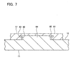
- Fig. 7 is a detailed diagram of section A of Fig. 6.
- a recess 82 with a round lateral cross section is formed in the bottom 81 of the pad 77.
- the recess 82 has a locking groove 83 which extends circumferentially.
- a protrusion 84 with a round lateral cross section is formed in the bottom 12 of the fuel tank 11.
- a lip shaped locking hook 85 is formed in the top edge of the protrusion 84.
- the fuel pump 10 is secured to the fuel tank 11 by locking the locking hook 85 of the fuel tank 11 into the locking groove 83 of the pad 77.
- the protruding wall 75 shown in the third representative embodiment may be formed in the fuel tank 11. If a protruding wall 75 is established, determining the position for locking the locking hook 85 of the fuel tank 11 to the locking groove 83 of the pad 77 will be simplified.
- an upward facing edge 88 is formed in the pad 87.
- a locking groove 89 which extends in the circumferential direction is formed in the outer circumference of the edge of the edge 88.
- a tank recess 90 is formed by a protruding wall 86 and the bottom 12 of the fuel tank 11. The planar configuration of the tank recess 90 is round.
- a locking hook 91 which extends in the circumferential direction is formed in the top end of the protruding wall 86. The fuel pump 10 is secured to the fuel tank 11 by locking the locking hook 91 of the fuel tank 11 into the locking groove 89 of the pad 87.
- a major portion of the pump body 31 of the fuel pump 10 is covered by a rubber vibration absorbing cover 92.
- a fuel filter 93 is inserted into a side opening 92a in the vibration absorbing cover 92.
- a hook receiving unit 94 is formed in the bottom edge of the vibration absorbing cover 92.
- a tank recess 96 is formed by a protruding wall 95 in the bottom 12 of the fuel tank 11. The planar configuration of the tank recess 96 is round.
- a locking hook 99 which extends circumferentially is formed in the top edge of the protruding wall 95.
- the fuel pump 10 is secured to the fuel tank 11 by locking the locking hook 99 into the hook accepting unit 94.
- the pump body 31 is covered by the vibration absorbing cover 92, so the amount of vibration of the fuel pump 10 which is transferred externally will be reduced, and vehicle quietness will be further enhanced.
Landscapes
- Engineering & Computer Science (AREA)
- Mechanical Engineering (AREA)
- General Engineering & Computer Science (AREA)
- Chemical & Material Sciences (AREA)
- Combustion & Propulsion (AREA)
- Cooling, Air Intake And Gas Exhaust, And Fuel Tank Arrangements In Propulsion Units (AREA)
Abstract

Description
- The present invention relates to a fuel tank unit having a fuel tank and a fuel pump, and more particularly to technology to attach the fuel pump to the fuel tank.
- Japanese Laid-open Patent Publication No. 5-305827 describes a fuel tank unit. This fuel tank unit comprises a fuel tank and a fuel pump disposed within the fuel tank. The fuel pump supplies fuel from the fuel tank to an internal combustion engine of a vehicle. When the vehicle goes around a curve or during rapid starting or stopping, the level of the fuel in the fuel tank will change dramatically. Therefore, the fuel pump is located at the bottom in the center of the fuel tank where the depth of the fuel is stable even when the level of the fuel in the fuel tank changes dramatically. The fuel pump is mounted on one end of a pump support member, and positioned at the center of the bottom of the fuel tank. The other end of the pump support member is attached to the lid on the top of the fuel tank.
- Improving comfort in vehicles, demands for flattening the fuel tank and conserving the space above the fuel tank have been steadily increasing in recent years. The lid of the fuel tank has a union and a connector protruding and facing outward, with a fuel supply line is connected to the union, and a wire harness which supplies electrical power to the fuel pump connected to the connector. Space is required above the lid in order to arrange the union, the connector, the fuel supply line, and the harness. Conventionally, with a construction where the lid is located above the fuel tank, the space above the fuel tank cannot be conserved.
Accordingly, it is one object of the present teachings to provide a fuel tank unit which can conserve the space above the fuel tank. - In one aspect of the present teachings, fuel tank unit may comprise a fuel tank, a fuel pump, and a pad. The fuel pump may be attached to the bottom of the inside of the fuel tank. The pad is preferably located between the fuel tank and the fuel pump. The pad is preferably made of resin material (e.g., plastic). The fuel tank may have a flat box shape exterior. Preferably, at least a part of the top circumferential edge of the outside of the fuel tank is beveled. The fuel tank may have a lid in the region where the edge has been beveled. The fuel pump may be located substantially in the center of the inside bottom of the fuel tank. The space above the fuel tank can be conserved by having the lid at the location where the edge on outside of the fuel tank has been beveled.
- If the lid is located in the region where the edge of the outside of the fuel tank has been beveled and the fuel pump is located in the center of the bottom of the fuel tank, the length of the pump support member must be longer than if the lid is located on the top surface of the fuel tank. A flat fuel tank enhances this tendency. The rigidity of the pump support member decreases as the length increases. If the rigidity of the pump support member is low, the fuel pump itself will vibrate strongly when operating. If the fuel pump vibrates strongly, the vibrations will be transferred to the vehicle through the pump support member and cause a large noise. Rashly increasing the rigidity of the pump support member is impractical because of the cost or the like. The fuel tank unit comprises a pad which is located between the fuel tank and the fuel pump. Therefore, a pump support member which is attached to the lid and supports the fuel pump is not necessary. Therefore, there will not be a loud noise from the fuel pump caused by the low rigidity of the fuel pump member. Furthermore, the noise produced by the fuel pump can be reduced by the vibration absorbing effect of the pad.
- In another aspect of the present teachings, the fuel pump may have a substantially disc shaped impeller and a casing which rotatably accommodates the impeller. The pad may be formed as a sheet. The casing of the fuel pump may be attached to the top surface of the pad. With a fuel tank unit with this type of construction, the vibration transferred from the fuel pump casing to the fuel tank is effectively suppressed by the pad.
The inside surface of the casing of the fuel pump may have a fuel intake opening. The fuel pump may be attached to the fuel tank by the attracting action of a magnetic located in the bottom of the fuel tank. - In another aspect of the present teachings, a recess may be formed on one side of the fuel tank and pad. A protrusion may be formed on the other side of the fuel tank and pad. The pad may be attached to the fuel tank by press fitting the protrusion into the recess.
- In another aspect of the present teachings, a hook accepting unit may be formed on one side of the fuel tank and pad. A hook may be established on the other side of the fuel tank and pad. The pad may be attached to the fuel tank by hooking the hook into the hook accepting unit.
- In another aspect of the present teachings, the fuel tank may have a member for determining the position of the pad. The member may be formed in the bottom of the fuel tank. If the member is formed to position the pad in the bottom of the fuel tank, positioning will be simplified when the fuel pump is to be attached inside the fuel tank.
- These aspects and features may be utilized singularly or, in combination, in order to make improved fuel pump. In addition, other objects, features and advantages of the present teachings will be readily understood after reading the following detailed description together with the accompanying drawings and claims. Of course, the additional features and aspects disclosed herein also may be utilized singularly or, in combination with the above-described aspect and features.
-
- Fig. 1 is an internal component diagram of a fuel tank unit of a first representative embodiment of the present teachings.
- Fig. 2 is a vertical cross section diagram of a fuel pump and fuel tank of the first representative embodiment.
- Fig. 3 is a perspective view diagram of a pad of the first representative embodiment.
- Fig. 4 is a vertical cross section diagram of a fuel pump and fuel tank of a second representative embodiment of the present teachings.
- Fig. 5 is a vertical cross section diagram of a fuel pump and fuel tank of a third representative of the present teachings.
- Fig. 6 is a vertical cross section diagram of a fuel pump and fuel tank of a fourth representative embodiment of the present teachings.
- Fig. 7 is a detailed diagram of region A of Fig. 6.
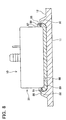
- Fig. 8 is a vertical cross section diagram of a fuel pump and fuel tank of a fifth representative embodiment of the present teachings.
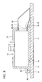
- Fig. 9 is a vertical cross section diagram of a fuel pump and fuel tank of a sixth representative embodiment of the present teachings.
- A fuel tank unit according to a first representative embodiment of the present teachings will be described while referring to the drawings. The fuel tank unit of the present embodiment may be used in a motor vehicle. As shown in Fig. 1, the fuel tank unit comprises a
fuel pump 10 and afuel tank 11.
Thefuel pump 10 supplies fuel to an engine of the motor vehicle. Thefuel pump 10 is attached to the bottom 12 of thefuel tank 11. Thefuel tank 11 may have a flat box shape. Thefuel tank 11 may be made from resin material (e.g., plastic). When the vehicle goes around a curve or accelerates or decelerates, thelevel 13 of the fuel in thefuel tank 11 will change. Therefore, thefuel pump 10 is preferably located in the center region of thefuel tank 11 where the change in the depth of the fuel is stable even if thelevel 13 of the fuel in thefuel tank 11 changes. - The
fuel tank 11 may comprise afuel tank body 11a and a set plate (tank lid) 14. Thefuel tank body 11 a has a flat box shaped exterior and is formed such that a part of the top circumferential edge is beveled. Anopening 11b is formed on the beveled region. Theset plate 14 is attached to theopening 11b. Aunion 15 and anelectrical connector 16 are fixed to theset plate 14. Theunion 15 and thefuel pump 10 are connected together by afuel hose 20. Theelectrical connector 16 and thefuel pump 10 are connected by awire harness 21. The fuel which is drawn into thefuel pump 10 flows through thefuel hose 20 and theunion 15 and is pumped out of thefuel tank 11. The fuel which is pumped out of thefuel tank 11 is supplied to the engine. Thefuel pump 10 is provided electrical power from the outside through theconnector 16 and thewire harness 21. - Conventionally, the set plate was attached to the top surface of the fuel tank. Therefore, space above the fuel tank is required for the fuel hose which is externally connected through the union and the wire harness which is externally connected to the electrical connector. If the space above the fuel tank is used, the comfort of the vehicle will be hindered. As described above, the
fuel tank 11 has a flat box shape and theset plate 14 is positioned at an angle in the region where part of the upper circumferential edge of the fuel tank has been beveled. Therefore, thefuel tank 11 of the present embodiment is flat and contributes to improved comfort in the vehicle by conserving the space above the fuel tank. - As shown in Fig. 2, the
fuel pump 10 has apump body 31. Apad 63 is attached to the bottom of thepump body 31. Thepump body 31 is attached to the bottom 12 of thefuel tank 11 through thepad 63.
Thepump body 31 comprises ahousing 30, acircuit section 32, and a pump section 43. Thehousing 30 has a substantially cylindrical shape on the bottom, and thecircuit section 32 and the pump section 43 are accommodated by crimping the top edge inward. Thehousing 30 may be made of steel. - The
circuit section 32 comprises acircuit casing 33 and acircuit board 34. Thecircuit casing 33 has adischarge port 36 which opens facing upward. One end of the fuel hose 20 (shown in Fig. 1) is connected to thedischarge port 36. Abead 36a extending in the circumferential direction is formed on the outside surface of thedischarge port 36. Thebead 36a is established in order to positively connect thefuel hose 20 to thedischarge port 36, or in other words to prevent thefuel hose 20 from separating from thedischarge port 36. A terminal 37 is established on the top surface of thecircuit casing 33. One end of the wire harness 21 (shown in Fig. 1) is connected to the terminal 37.
Thecircuit board 34 is accommodated in the space inside thecircuit casing 33 by means of aboard base 35. Amotor control circuit 41 is attached to thecircuit board 34. Themotor control circuit 41 converts the direct current power supplied from the outside through the terminal 37 into three-phase alternating current power. This alternating current power is supplied by an electricalpower supply line 42 to a drive coil 61 (described later). - The pump section 43 comprises a
pump casing 44 and animpeller 45. Thepump casing 44 accommodates theimpeller 45. Theimpeller 45 is formed in a substantially disc shape and is attached through abearing 51 to ashaft 48 which is attached to thepump casing 44. A small gap is established between thepump casing 44 and the top, bottom, and outside circumferential surfaces of theimpeller 45. Therefore, theimpeller 45 rotates around theshaft 48 while accommodated in thepump casing 44. A group ofconcavities 46 and a group ofconcavities 47 are formed in upper and lower faces of theimpeller 45. The group ofconcavities impeller 45. Theconcavities upper concavities 46 and lower concavities communicates via through-hole. A plurality ofpermanent magnets 52 is disposed in the impeller. The permanent magnets are located on the top side of theimpeller 45 toward the inside of theconcavities 46. - A
top surface groove 53 which extends from the upstream end to the downstream end is formed on the surface opposite to the top surface of theimpeller 45 of thepump casing 44 in the region corresponding to the group ofconcavities 46 of theimpeller 45. The upstream end of thetop surface groove 53 is connected through to the outside by anintake channel 55 which is formed in thepump casing 44. The downstream end of thetop surface groove 53 is connected through to adischarge port 36 through adischarge channel 57 which is formed in thepump casing 44.
Abottom surface groove 54 which extends from the upstream end to the downstream end is formed on the surface opposite to the bottom surface of theimpeller 45 of thepump casing 44 in the region corresponding to the group ofconcavities 47 of theimpeller 45. The upstream end of thebottom surface groove 54 is connected through to the outside through theintake channel 56, and the downstream end is connected through to thedischarge port 36 through thedischarge channel 58. - Drive coils 61 is attached to the
pump casing 44 in the region opposite thepermanent magnets 52. As previously described, electrical power is supplied from themotor control circuit 41 through thepower supply line 42 to the drive coils 61. When electrical power supplied to the drive coils 61, theimpeller 45 will rotate because of the magnetic effect generated thereby.
When theimpeller 45 rotates, fuel will circulate through each of theconcavities 46 and thetop surface groove 53. While circulating, the fuel flows from the upstream end of thetop surface groove 53 to the downstream end, and is pressurized in the process. As a result, fuel from the outside will be drawn in through theintake channel 55, flow through thetop channel groove 53 from the upstream end to the downstream end, and be discharged from thedischarge channel 57. The fuel which is discharged from thedischarge channel 57 is transferred to thedischarge port 36, and is discharged from thedischarge port 36 to thefuel hose 20. Similarly, fuel is also drawn into theintake channel 56, flows through thebottom surface groove 54 and is discharged from thedischarge channel 58. The fuel which is discharged from thedischarge channel 58 is transported to thedischarge port 36, and is discharged from thedischarge port 36 to thefuel hose 20. - The
pad 63 is made from rubber, and as shown in Fig. 2 and Fig. 3, an upward facinglip 65 is established on the outer circumference of the disc shapedbottom 64. Anotch 66 is formed in thelip 65. Thenotch 66 is located in a position which corresponds to theintake channel 56 of thepump body 31. Therefore, thelip 65 is prevented from plugging theintake channel 56. The inside diameter of thelip 65 is slightly smaller than the outside diameter of thepump body 31. Therefore, thepump body 31 is attached to thepad 63 by being press fit into thelip 65. Attaching thepump body 31 to thepad 63 is not restricted to press fitting, and for instance, an adhesive may also be used. Arecess 67 which opens facing downward is formed in the bottom surface of the bottom 64. The lateral cross-section of therecess 67 is round. - The
fuel tank 11 is made of plastic. As shown in Fig. 2, amagnet 71 is attached to thefuel tank 11 such that the top of the magnet protrudes from the bottom 12 of the fuel tank. Themagnet 71 has a cylindrical shape and the outside diameter is slightly smaller than the inside diameter of therecess 67 in thepad 63. Themagnet 71 may be attached to the bottom 12 of thefuel tank 11 by adhesive or press fitting or the like.
As previously described, thehousing 30 of thepump body 31 is made of steel. Therefore, thehousing 30 will be acted on by the magnetic attraction of themagnet 71 through thepad 63. Thefuel pump 10 is fixed to the bottom 12 of thefuel tank 11 by the magnetic attraction of themagnet 71 on thehousing 30. - As previously described, the
set plate 14 of thefuel tank 11 is positioned in the region where a part of the upper circumferential edge of thefuel tank 11 was beveled. Furthermore, thefuel pump 10 is attached to the center of the bottom of thefuel tank 11. Therefore, an operator must attach thefuel pump 10 in a position deep within thefuel tank 11 when theset plate 14 is removed. As described above, arecess 67 is formed in the bottom 64 of thepad 63 and amagnet 71 protrudes out from the bottom 12 of thefuel tank 11. Therefore, by adjusting the position of thefuel pump 10 so that the protruding portion of themagnet 71 will fit into therecess 67 of thepad 63, the position of thefuel pump 10 can easily be set. Other operations are not required because thefuel pump 10 will be secured by the magnetic attraction of themagnet 71. With this type of construction, thefuel pump 10 can easily be attached in a position deep within thefuel tank 11, and therefore the cost will be inexpensive. - Conventionally, one end of the pump supporting member is attached to the set plate and the fuel pump is attached to the other end of the pump support member so the fuel pump is normally suspended down and positioned in the fuel tank. However, if the set plate is located in the region where the upper edge of the fuel tank has been beveled and the fuel pump is to be positioned at a location in the center of the bottom of the fuel tank, the length of the pump support member must be made longer. When the length of the pump support member is increased, the rigidity will be insufficient. Furthermore when the length of the pump support member is increased, the fuel pump will vibrate strongly when functioning. If the fuel pump vibrates strongly, large quantities of abrasion powder will be generated because of strong contact between the internal metal components. When large quantities of abrasion powder are generated, the fuel pump will be damaged. Furthermore, when the fuel pump vibrates strongly, the vibrations will transfer through the pump support member to the fuel tank and noise will be generated. However, rashly increasing the strength of the pump support member is impractical because of the cost or the like.
- The
fuel pump 10 of the present embodiment is attached to afuel tank 11 through thepad 63. Therefore a pump support member is not necessary. Furthermore, the aforementioned problems caused by the length of the pump support member can be prevented. Moreover thepad 63 is made from rubber. Therefore, vibrations which transfer from thepump body 31 to the vehicle are reduced by the vibration absorbing effects of thepad 63. Therefore, the quietness of the vehicle can be enhanced.
It is also possible formagnet 71 to be attached to thepump body 31, and the region which is attracted by themagnet 71 may be on the fuel tank side. - Descriptions which are duplicate with those of the first representative embodiment will be omitted, and only the content which is characteristic to the present embodiment will be described. (The same applies to the third through sixth representative embodiments which will be described later).
As shown in Fig. 4, an upwardfacing protruding part 73 is formed in the bottom 12 of thefuel tank 11. The protrudingpart 73 has a cylindrical shape and the diameter is slightly larger than therecess 67 in thepad 63. Thefuel pump 10 is attached to the bottom 12 of the fuel tank I 1 by press fitting theprotruding part 73 of thefuel tank 11 into therecess 67 in thefuel pad 63. With this preferred embodiment, thefuel pump 10 can be attached to thefuel tank 11 by a simplified construction. - As shown in Fig. 5, a protruding
part 74 is formed in the bottom 12 of thefuel tank 11, similar to the second representative embodiment. Furthermore, atank recess 67 is formed in the bottom 12 of thefuel tank 11 by an upward protrudingwall 75. Thetank recess 76 has a cylindrical plane. The protrudingwall 75 of thetank recess 76 is formed such that the side further from the set plate 14 (left-hand side in Fig. 5) is taller than the side near the set plate 14 (right hand side in Fig. 5). Therefore, when the operator attaches thefuel pump 10, the protrudingwall 75 on the side further from theset plate 14 will function as a stopper, and the position of thefuel pump 10 can be more easily set. Thefuel pump 10 is attached to the bottom 12 of thefuel tank 11 by press fitting theprotruding part 74 of thefuel tank 11 into therecess 67 in thepad 63. - As shown in Fig. 6, with this embodiment the
fuel pump 10 is attached to thefuel tank 11 by locking thepad 77 of thefuel pump 10 into the bottom 12 of thefuel tank 11. Fig. 7 is a detailed diagram of section A of Fig. 6. As shown in Fig. 7, arecess 82 with a round lateral cross section is formed in the bottom 81 of thepad 77. Therecess 82 has a lockinggroove 83 which extends circumferentially. Aprotrusion 84 with a round lateral cross section is formed in the bottom 12 of thefuel tank 11. A lip shaped lockinghook 85 is formed in the top edge of theprotrusion 84. Thefuel pump 10 is secured to thefuel tank 11 by locking the lockinghook 85 of thefuel tank 11 into the lockinggroove 83 of thepad 77.
In addition to the aforementioned configuration, the protrudingwall 75 shown in the third representative embodiment may be formed in thefuel tank 11. If a protrudingwall 75 is established, determining the position for locking the lockinghook 85 of thefuel tank 11 to the lockinggroove 83 of thepad 77 will be simplified. - As shown in Fig. 8, an upward facing
edge 88 is formed in thepad 87. A lockinggroove 89 which extends in the circumferential direction is formed in the outer circumference of the edge of theedge 88. Atank recess 90 is formed by a protrudingwall 86 and the bottom 12 of thefuel tank 11. The planar configuration of thetank recess 90 is round. A lockinghook 91 which extends in the circumferential direction is formed in the top end of the protrudingwall 86. Thefuel pump 10 is secured to thefuel tank 11 by locking the lockinghook 91 of thefuel tank 11 into the lockinggroove 89 of thepad 87. - As shown in Fig. 9, a major portion of the
pump body 31 of thefuel pump 10 is covered by a rubbervibration absorbing cover 92. Afuel filter 93 is inserted into aside opening 92a in thevibration absorbing cover 92. Ahook receiving unit 94 is formed in the bottom edge of thevibration absorbing cover 92. Atank recess 96 is formed by a protrudingwall 95 in the bottom 12 of thefuel tank 11. The planar configuration of thetank recess 96 is round. A lockinghook 99 which extends circumferentially is formed in the top edge of the protrudingwall 95. Thefuel pump 10 is secured to thefuel tank 11 by locking the lockinghook 99 into thehook accepting unit 94. Thepump body 31 is covered by thevibration absorbing cover 92, so the amount of vibration of thefuel pump 10 which is transferred externally will be reduced, and vehicle quietness will be further enhanced. - Finally, although the preferred representative embodiments have been described in detail, the present embodiments are for illustrative purpose only and not restrictive. It is to be understood that various changes and modifications may be made without departing from the spirit or scope of the appended claims. In addition, the additional features and aspects disclosed herein also may be utilized singularly or in combination with the above aspects and features.
It is explicitly stated that all features disclosed in the description and/or the claims are intended to be disclosed separately and independently from each other for the purpose of original disclosure as well as for the purpose of restricting the claimed invention independent of the composition of the features in the embodiments and/or the claims. It is explicitly stated that all value ranges or indications of groups of entities disclose every possible intermediate value or intermediate entity for the purpose of original disclosure as well as for the purpose of restricting the claimed invention, in particular as limits of value ranges.
Claims (8)
- A fuel tank unit, comprising:a fuel tank comprising a fuel tank body and a lid, wherein the fuel tank body has a flat box shaped exterior, wherein at least a portion of the top circumferential edge of the outside of the fuel tank body is beveled, and wherein the lid is attached to the beveled region of the fuel tank body;a fuel pump attached to the bottom of the inside of the fuel tank body, the fuel pump being located substantially at the center of the inside bottom of the fuel tank body; anda pad located between the fuel tank and the fuel pump.
- A fuel tank unit as in claim 1, wherein the pad is made of resin material.
- A fuel tank unit as in claim 1, wherein the fuel pump has a substantially disc shaped impeller and a casing which rotatably accommodates the impeller, wherein the pad is formed as a sheet, and wherein the casing of the fuel pump is attached to the top surface of the pad.
- A fuel tank unit as in claim 3, wherein a fuel intake opening is formed in the side surface of the fuel pump casing.
- A fuel tank unit as in claim 1, wherein the fuel pump is attached to the fuel tank by the attractive force of a magnet which is attached to the bottom of the fuel tank body.
- A fuel tank unit as in claim 1, wherein a recess is formed in one of either the fuel tank or the pad, wherein a protrusion is formed in the other of either the fuel tank or the pad, and wherein the pad is attached to the fuel tank by the protrusion being press-fit into the recess.
- A fuel tank unit as in claim 1, wherein a hook receiving unit is formed in one of either the fuel tank or the pad, wherein a locking hook is formed in the other of either the fuel tank or the pad, and wherein the pad is attached to the fuel tank by hooking the locking hook into the hook receiving unit.
- A fuel tank unit as in claim 1, wherein the fuel tank further comprise a member for determining the position of the pad, the member being formed in the bottom of the fuel tank body.
Applications Claiming Priority (1)
| Application Number | Priority Date | Filing Date | Title |
|---|---|---|---|
| JP2004210978A JP2006029244A (en) | 2004-07-20 | 2004-07-20 | Fuel tank unit |
Publications (1)
| Publication Number | Publication Date |
|---|---|
| EP1619381A1 true EP1619381A1 (en) | 2006-01-25 |
Family
ID=34937878
Family Applications (1)
| Application Number | Title | Priority Date | Filing Date |
|---|---|---|---|
| EP20050015658 Withdrawn EP1619381A1 (en) | 2004-07-20 | 2005-07-19 | Fuel tank unit for a motor vehicle |
Country Status (3)
| Country | Link |
|---|---|
| US (1) | US7201151B2 (en) |
| EP (1) | EP1619381A1 (en) |
| JP (1) | JP2006029244A (en) |
Families Citing this family (15)
| Publication number | Priority date | Publication date | Assignee | Title |
|---|---|---|---|---|
| DE10322621B4 (en) * | 2003-05-20 | 2006-05-04 | Siemens Ag | For attachment in a fuel tank provided delivery unit |
| JP2008007137A (en) * | 2006-06-27 | 2008-01-17 | Yanmar Co Ltd | Engine-driven type refrigerated container |
| US20080299517A1 (en) * | 2007-06-01 | 2008-12-04 | Delaney Ii Page W | Denture with suction attachment |
| FR2917791B1 (en) * | 2007-06-20 | 2009-08-21 | Inergy Automotive Systems Res | METHOD FOR STARTING A PUMP |
| US8529216B2 (en) * | 2007-07-30 | 2013-09-10 | Continental Automotive Systems, Inc. | Jet pump retention and seal method with living hinge |
| US20090266830A1 (en) * | 2008-04-24 | 2009-10-29 | Benjey Robert P | Fluid container component assembly |
| JP5436826B2 (en) | 2008-09-30 | 2014-03-05 | 愛三工業株式会社 | Fuel tank |
| EP3004644A4 (en) | 2013-05-31 | 2017-08-23 | Intellectual Property Holdings, LLC | Natural gas compressor |
| DE102015221377A1 (en) | 2015-11-02 | 2017-05-04 | Ti Automotive Technology Center Gmbh | Plastic container with cup-like body |
| JP6575497B2 (en) * | 2016-12-07 | 2019-09-18 | トヨタ自動車株式会社 | Pump module assembly structure |
| CN110486298A (en) * | 2019-08-02 | 2019-11-22 | 烟台菱辰能源有限公司 | A vortex hydrogen circulation pump based on a disc motor structure |
| KR102212672B1 (en) * | 2020-03-17 | 2021-02-05 | 현담산업 주식회사 | Fixation apparatus of fuel pump |
| US12012915B2 (en) * | 2021-02-09 | 2024-06-18 | Honda Motor Co., Ltd. | Pump cover attachment system |
| EP4052946B1 (en) * | 2021-03-05 | 2024-05-01 | Magna Energy Storage Systems GesmbH | Plastic tank |
| KR20230028825A (en) * | 2021-08-23 | 2023-03-03 | 현대자동차주식회사 | Fuel pump module for vehicle |
Citations (10)
| Publication number | Priority date | Publication date | Assignee | Title |
|---|---|---|---|---|
| US4750513A (en) * | 1987-11-19 | 1988-06-14 | Chrysler Motors Corporation | Pivotally mounted fuel collector |
| US4844621A (en) * | 1985-08-10 | 1989-07-04 | Nippondenso Co., Ltd. | Fuel pump with passage for attenuating noise generated by impeller |
| DE3920276A1 (en) * | 1988-06-29 | 1990-01-04 | Volkswagen Ag | Internal tank pump, especially a fuel pump for a motor vehicle |
| EP0378796A2 (en) * | 1988-12-07 | 1990-07-25 | Nissan Motor Co., Ltd. | Fuel tank structure for automotive vehicle |
| EP0379631A1 (en) * | 1988-12-20 | 1990-08-01 | VDO Adolf Schindling AG | Fuel-pumping device |
| JPH05305827A (en) | 1992-04-30 | 1993-11-19 | Kurata:Kk | Fuel storage container support structure |
| EP0875411A2 (en) * | 1997-04-28 | 1998-11-04 | SOLVAY (Société Anonyme) | Plastic hollow body with internal fastening arrangement |
| US20030102035A1 (en) * | 2001-11-30 | 2003-06-05 | Dasilva Antonio J. | Fuel tank assembly |
| WO2003062627A1 (en) * | 2002-01-24 | 2003-07-31 | Mikuni Corporation | Fuel feeder |
| DE10355689A1 (en) * | 2003-11-28 | 2005-07-14 | Dr.Ing.H.C. F. Porsche Ag | Fuel delivery system holding device for use in fuel tank of motor vehicle, has lock device formed at face of pump via two receptacle units, and safety lug to fix pump in final position |
Family Cites Families (5)
| Publication number | Priority date | Publication date | Assignee | Title |
|---|---|---|---|---|
| DE1947505A1 (en) * | 1969-09-19 | 1971-06-16 | Bosch Gmbh Robert | Suspension device for an electric fuel pump |
| US4651701A (en) * | 1986-02-13 | 1987-03-24 | Steart-Warner Corp. | Submersible fuel pump and sender assembly |
| EP0314068B1 (en) * | 1987-10-26 | 1994-01-19 | Nippondenso Co., Ltd. | Fuel supply device for vehicles |
| JPH08225023A (en) | 1995-12-07 | 1996-09-03 | Nifco Inc | Swirling tank device for automobile fuel tank |
| US6830687B2 (en) * | 2003-01-21 | 2004-12-14 | Delphi Technologies, Inc. | Fuel strainer assembly |
-
2004
- 2004-07-20 JP JP2004210978A patent/JP2006029244A/en active Pending
-
2005
- 2005-07-19 EP EP20050015658 patent/EP1619381A1/en not_active Withdrawn
- 2005-07-20 US US11/184,947 patent/US7201151B2/en not_active Expired - Fee Related
Patent Citations (10)
| Publication number | Priority date | Publication date | Assignee | Title |
|---|---|---|---|---|
| US4844621A (en) * | 1985-08-10 | 1989-07-04 | Nippondenso Co., Ltd. | Fuel pump with passage for attenuating noise generated by impeller |
| US4750513A (en) * | 1987-11-19 | 1988-06-14 | Chrysler Motors Corporation | Pivotally mounted fuel collector |
| DE3920276A1 (en) * | 1988-06-29 | 1990-01-04 | Volkswagen Ag | Internal tank pump, especially a fuel pump for a motor vehicle |
| EP0378796A2 (en) * | 1988-12-07 | 1990-07-25 | Nissan Motor Co., Ltd. | Fuel tank structure for automotive vehicle |
| EP0379631A1 (en) * | 1988-12-20 | 1990-08-01 | VDO Adolf Schindling AG | Fuel-pumping device |
| JPH05305827A (en) | 1992-04-30 | 1993-11-19 | Kurata:Kk | Fuel storage container support structure |
| EP0875411A2 (en) * | 1997-04-28 | 1998-11-04 | SOLVAY (Société Anonyme) | Plastic hollow body with internal fastening arrangement |
| US20030102035A1 (en) * | 2001-11-30 | 2003-06-05 | Dasilva Antonio J. | Fuel tank assembly |
| WO2003062627A1 (en) * | 2002-01-24 | 2003-07-31 | Mikuni Corporation | Fuel feeder |
| DE10355689A1 (en) * | 2003-11-28 | 2005-07-14 | Dr.Ing.H.C. F. Porsche Ag | Fuel delivery system holding device for use in fuel tank of motor vehicle, has lock device formed at face of pump via two receptacle units, and safety lug to fix pump in final position |
Also Published As
| Publication number | Publication date |
|---|---|
| US7201151B2 (en) | 2007-04-10 |
| JP2006029244A (en) | 2006-02-02 |
| US20060016485A1 (en) | 2006-01-26 |
Similar Documents
| Publication | Publication Date | Title |
|---|---|---|
| US7201151B2 (en) | Fuel tank unit | |
| US5038741A (en) | In-tank fuel module | |
| CN101741181B (en) | Motor for field of heating ventilation air conditioning | |
| US20040234395A1 (en) | Magnetic coupling pump | |
| US6702555B2 (en) | Fluid pump having an isolated stator assembly | |
| CN110323867B (en) | Motor and air supply device | |
| CN101013831A (en) | motor | |
| CN1959126A (en) | Centrifugal fan | |
| US20040234389A1 (en) | Waterpump | |
| CN107091249A (en) | Centrifugal pump | |
| US11742714B2 (en) | Motor and driving member | |
| CN111448395B (en) | Motor for drain pump, method for manufacturing the same, and drain pump having the same | |
| CN100521445C (en) | Electric motor for a fuel pump | |
| CN222526456U (en) | Reciprocating compressor, vehicle-mounted refrigerator and vehicle | |
| JP2005226832A (en) | Spherical bearing, electric motor and circulating pump | |
| JP2014152726A (en) | Fuel pump module | |
| JPH11218059A (en) | Fuel pump | |
| JP2005233067A (en) | Fuel supply device | |
| JP2003097375A (en) | Motor type fuel pump for vehicles | |
| JPH08275438A (en) | motor | |
| CN101010852B (en) | Devices for containing electric motors and electric motors | |
| US7950898B2 (en) | Fuel pump having impeller | |
| CN215672695U (en) | Electric pump and vehicle loading device | |
| JP2510153B2 (en) | Fluid pump | |
| JP4143851B2 (en) | Fuel supply device |
Legal Events
| Date | Code | Title | Description |
|---|---|---|---|
| PUAI | Public reference made under article 153(3) epc to a published international application that has entered the european phase |
Free format text: ORIGINAL CODE: 0009012 |
|
| 17P | Request for examination filed |
Effective date: 20050719 |
|
| AK | Designated contracting states |
Kind code of ref document: A1 Designated state(s): AT BE BG CH CY CZ DE DK EE ES FI FR GB GR HU IE IS IT LI LT LU LV MC NL PL PT RO SE SI SK TR |
|
| AX | Request for extension of the european patent |
Extension state: AL BA HR MK YU |
|
| AKX | Designation fees paid |
Designated state(s): DE FR IT |
|
| 17Q | First examination report despatched |
Effective date: 20070129 |
|
| 17Q | First examination report despatched |
Effective date: 20070129 |
|
| STAA | Information on the status of an ep patent application or granted ep patent |
Free format text: STATUS: THE APPLICATION IS DEEMED TO BE WITHDRAWN |
|
| 18D | Application deemed to be withdrawn |
Effective date: 20070706 |