EP1619112A1 - Arrangement of air cleaner for scooters - Google Patents
Arrangement of air cleaner for scooters Download PDFInfo
- Publication number
- EP1619112A1 EP1619112A1 EP04016961A EP04016961A EP1619112A1 EP 1619112 A1 EP1619112 A1 EP 1619112A1 EP 04016961 A EP04016961 A EP 04016961A EP 04016961 A EP04016961 A EP 04016961A EP 1619112 A1 EP1619112 A1 EP 1619112A1
- Authority
- EP
- European Patent Office
- Prior art keywords
- air cleaner
- frame
- air
- recess
- arrangement
- Prior art date
- Legal status (The legal status is an assumption and is not a legal conclusion. Google has not performed a legal analysis and makes no representation as to the accuracy of the status listed.)
- Granted
Links
Images


Classifications
-
- B—PERFORMING OPERATIONS; TRANSPORTING
- B62—LAND VEHICLES FOR TRAVELLING OTHERWISE THAN ON RAILS
- B62K—CYCLES; CYCLE FRAMES; CYCLE STEERING DEVICES; RIDER-OPERATED TERMINAL CONTROLS SPECIALLY ADAPTED FOR CYCLES; CYCLE AXLE SUSPENSIONS; CYCLE SIDECARS, FORECARS, OR THE LIKE
- B62K19/00—Cycle frames
- B62K19/30—Frame parts shaped to receive other cycle parts or accessories
-
- F—MECHANICAL ENGINEERING; LIGHTING; HEATING; WEAPONS; BLASTING
- F02—COMBUSTION ENGINES; HOT-GAS OR COMBUSTION-PRODUCT ENGINE PLANTS
- F02M—SUPPLYING COMBUSTION ENGINES IN GENERAL WITH COMBUSTIBLE MIXTURES OR CONSTITUENTS THEREOF
- F02M35/00—Combustion-air cleaners, air intakes, intake silencers, or induction systems specially adapted for, or arranged on, internal-combustion engines
- F02M35/16—Combustion-air cleaners, air intakes, intake silencers, or induction systems specially adapted for, or arranged on, internal-combustion engines characterised by use in vehicles
- F02M35/162—Motorcycles; All-terrain vehicles, e.g. quads, snowmobiles; Small vehicles, e.g. forklifts
-
- B—PERFORMING OPERATIONS; TRANSPORTING
- B62—LAND VEHICLES FOR TRAVELLING OTHERWISE THAN ON RAILS
- B62K—CYCLES; CYCLE FRAMES; CYCLE STEERING DEVICES; RIDER-OPERATED TERMINAL CONTROLS SPECIALLY ADAPTED FOR CYCLES; CYCLE AXLE SUSPENSIONS; CYCLE SIDECARS, FORECARS, OR THE LIKE
- B62K2202/00—Motorised scooters
-
- F—MECHANICAL ENGINEERING; LIGHTING; HEATING; WEAPONS; BLASTING
- F02—COMBUSTION ENGINES; HOT-GAS OR COMBUSTION-PRODUCT ENGINE PLANTS
- F02M—SUPPLYING COMBUSTION ENGINES IN GENERAL WITH COMBUSTIBLE MIXTURES OR CONSTITUENTS THEREOF
- F02M35/00—Combustion-air cleaners, air intakes, intake silencers, or induction systems specially adapted for, or arranged on, internal-combustion engines
- F02M35/02—Air cleaners
Definitions
- This invention is related to an improvement in the arrangement of an air cleaner for scooters, and in particular to one for scooters with large cylinder volume.
- the air cleaner 14 is fixedly mounted on the transmission box 132 of the power unit 13, so that when the scooter 1 goes to make the power unit 13 oscillate, the air cleaner 14 will oscillate with the power unit 13. Hence, it is impossible to arrange any other component part(s) within the range of the oscillation.
- the arrangement of the air cleaner 14 is only suitable for scooters with small cylinder volume. As for scooters with large cylinder volume, the transmission box 132 will be larger than that of scooters with small cylinder volume, and so arrangement space of the air cleaner 14 will be limited. Furthermore, the air cleaner 14 will probably interfere with other machine parts when the air cleaner 14 is oscillated with the power unit 13.
- the scooter 2 is provided with a power unit 23 under the seat 21 and the compartment 22.
- the power unit 23 comprises an engine 231, a transmission box 232, a crankshaft case 233 and a gear box 234.
- the transmission box 232 forms a left fork LF of the power unit 23
- a rod S forms a right fork RF of the power unit 23.
- the gear box 234, the left fork LF and the right fork RF constitute a U-shaped frame which will oscillate with respect to the crankshaft 2331, thereby making it impossible to mount the air cleaner 24 on the transmission box 232.
- the air cleaner 24 must be mounted under the compartment between two sides of the frame P, thus limiting the volume of the compartment 22 and therefore making it unfit for practical use.
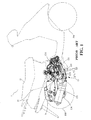
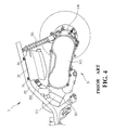
- FIG 4 illustrates another conventional arrangement of the air cleaner in a scooter.
- the scooter 3 is provided with a power unit 31 under the seat and the compartment.
- the power unit 31 includes an engine 311, a transmission box 312, a crankshaft case 313 and a gear box 314.
- the air cleaner 32 is fixedly mounted on the frame P2 by screws extending through the lugs Pe on the frame P2.
- the air inlet 321 and the air outlet 322 of the air cleaner 32 are installed right under the frame P2, so that the body of the air cleaner 32 has to extend downwardly thereby increasing the vertical size and therefore limiting the design of the body cover in vertical direction.
- an object of the present invention to provide an improvement in the arrangement of an air cleaner for scooters which can obviate and mitigate the above-mentioned drawbacks.
- This invention is related to an improvement in the arrangement of an air cleaner for scooters, and in particular to one for scooters with large cylinder volume.
- a power unit 43 is mounted under a compartment 42 and a seat 41 of a scooter 4.
- the power unit 43 generally comprises an engine 431, a transmission box 432, and a gear box (not shown).
- the power unit 43 is used for supplying power to the scooter 4 and is well known in the art. Hence, it is no longer necessary to describe the power unit 43 here in detail.
- Above the transmission box 432 of the power unit 43 is mounted a shock absorber 44.
- the shock absorber 44 is connected between the transmission box 432 and the frame P3.
- the clean air required by the engine 431 of the power unit 43 is supplied by the air cleaner 5 which is fixedly mounted on the frame P3.
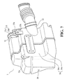
- the air cleaner 5 at least includes an air inlet 51 and an air outlet 52.
- One side of the air cleaner 5 is formed with a first recess 53 at the upper portion and a second recess 54 at the lower portion.
- the first recess 53 includes a vertical side 53a and a horizontal side 53b
- the second recess 54 includes a vertical side 54a and a horizontal side 54b.
- the vertical side 54a has a larger height than the vertical side 53a.
- the first recess 53 and the second recess 54 are designed to receive the frame P3 and the air outlet 52, respectively.
- the air cleaner 5 is provided with three lugs 55a, 55b and 55c and a threaded hole 56 close to the first recess 53, which are aligned with lugs Pe1, Pe2, Pe3 and Pe4 respectively, thereby enabling the air cleaner 5 to be conveniently fastened on the frame P3 by screws 6.
- the air cleaner 5 is fastened to the frame P3 by the screws 6 extending through the lugs 55a, 55b, 55c and threaded hole 56 and the ears Pe1, Pe2, Pe3 and Pe4.
- the air inlet 51 of the air cleaner 5 is arranged outside of the frame P3, i.e. between the frame P3 and the cover C.
- the frame P3 is disposed between the air inlet 51 and the air outlet 52 of the air cleaner 5 and located in the first recess 53.
- the compartment 42 is arranged in the second recess 54 of the air cleaner 5, so that the volume of the compartment 42 will be maximized.
- the air cleaner 5 is fastened to the frame P3 and disposed in front of the shock absorber 44 (see FIG 5). Moreover, the air inlet 51 and the air outlet 52 of the air cleaner 5 are arranged in the same direction. The air inlet 51 is arranged in parallel to one side of the frame P3.
- the present invention is characterized in that when the air cleaner 5 is fastened to the frame P3, the air inlet 51 of the air cleaner 5 will be installed between the outer side of the frame P3 and the inner side of the cover 3, while the air outlet 52 is arranged at the inner side of the frame P3.
- the space between the frame P3 and the cover C is fully utilized thereby increasing the space utilization efficiency of scooters.
- the air cleaner 5 will not move with the power unit 43 thereby effectively preventing the air cleaner 5 from getting interference with the large transmission box of scooters with large cylinder volume.
- the air inlet 51 of the air cleaner 5 is arranged between the frame P3 and the body cover C and the frame P3 is arranged in the first recess 53 thus providing a compact arrangement between the air cleaner 5 and the frame P3 and therefore reducing the influence of the arrangement of the air cleaner 5 to the other machine parts.
- the air cleaner 5 is fastened to the frame P3 in front of the shock absorber 44.
- the second recess 54 is located close to the compartment 42 thereby making the arrangement more compact and therefore effectively maximizing the space utilization of the scooter.
Landscapes
- Engineering & Computer Science (AREA)
- Mechanical Engineering (AREA)
- Chemical & Material Sciences (AREA)
- Combustion & Propulsion (AREA)
- General Engineering & Computer Science (AREA)
- Automatic Cycles, And Cycles In General (AREA)
- Filtering Of Dispersed Particles In Gases (AREA)
- Respiratory Apparatuses And Protective Means (AREA)
Abstract
Description
- This invention is related to an improvement in the arrangement of an air cleaner for scooters, and in particular to one for scooters with large cylinder volume.
- FIG 1 illustrates how the air cleaner is arranged in a conventional scooter. As shown, the conventional scooter 1 has a
seat 11 and acompartment 12 under which there is apower unit 13 having anengine 131, atransmission box 132, acrankshaft case 133, and agear box 134. The clean air required by theengine 131 is obtained from anair cleaner 14. Theair cleaner 14 is used for supplying clean air to mix with fuel oil to form fuel gas which is then transmitted to theengine 131 for combustion thereby generating power and therefore pushing thepiston 1311 to reciprocate rapidly. Then, thepiston 1311 drives thecrankshaft 1331 to rotate within thecrankshaft case 133 thus driving the belt transmission mechanism in thetransmission box 132. Thereafter, the belt transmission mechanism drives the gear train in thegear box 134 to drive the rear wheel which will in turn drive the front wheel to rotate, enabling the scooter 1 to travel. - However, the
air cleaner 14 is fixedly mounted on thetransmission box 132 of thepower unit 13, so that when the scooter 1 goes to make thepower unit 13 oscillate, theair cleaner 14 will oscillate with thepower unit 13. Hence, it is impossible to arrange any other component part(s) within the range of the oscillation. The arrangement of theair cleaner 14 is only suitable for scooters with small cylinder volume. As for scooters with large cylinder volume, thetransmission box 132 will be larger than that of scooters with small cylinder volume, and so arrangement space of theair cleaner 14 will be limited. Furthermore, theair cleaner 14 will probably interfere with other machine parts when theair cleaner 14 is oscillated with thepower unit 13. - In order to solve this problem, an arrangement of the air cleaner especially designed for scooters with large cylinder volume has been developed (see FIG 2). As illustrated, the
scooter 2 is provided with apower unit 23 under theseat 21 and thecompartment 22. Thepower unit 23 comprises anengine 231, atransmission box 232, acrankshaft case 233 and agear box 234. Referring to FIG 3, thetransmission box 232 forms a left fork LF of thepower unit 23, and a rod S forms a right fork RF of thepower unit 23. Thegear box 234, the left fork LF and the right fork RF constitute a U-shaped frame which will oscillate with respect to thecrankshaft 2331, thereby making it impossible to mount theair cleaner 24 on thetransmission box 232. Hence, theair cleaner 24 must be mounted under the compartment between two sides of the frame P, thus limiting the volume of thecompartment 22 and therefore making it unfit for practical use. - FIG 4 illustrates another conventional arrangement of the air cleaner in a scooter. As can be seen, the
scooter 3 is provided with apower unit 31 under the seat and the compartment. Thepower unit 31 includes anengine 311, atransmission box 312, acrankshaft case 313 and agear box 314. Theair cleaner 32 is fixedly mounted on the frame P2 by screws extending through the lugs Pe on the frame P2. Theair inlet 321 and theair outlet 322 of theair cleaner 32 are installed right under the frame P2, so that the body of theair cleaner 32 has to extend downwardly thereby increasing the vertical size and therefore limiting the design of the body cover in vertical direction. - It is, therefore, an object of the present invention to provide an improvement in the arrangement of an air cleaner for scooters which can obviate and mitigate the above-mentioned drawbacks.
- This invention is related to an improvement in the arrangement of an air cleaner for scooters, and in particular to one for scooters with large cylinder volume.
- It is the primary object of the present invention to provide an arrangement of an air cleaner for scooters wherein the air inlet of the air cleaner is arranged at one side of the frame, the air outlet of the air cleaner is mounted at the other side of the frame, and the air inlet of the air cleaner is installed between the frame and the body cover, so that frame is located between the air inlet and the air outlet thereby enabling the space between the frame and the body cover to be fully utilized and preventing the air cleaner from oscillating with the power unit and getting into interference with the other component parts.
- It is another object of the present invention to provide an arrangement of an air cleaner for scooters wherein air inlet of the air cleaner is arranged in parallel to one side of the frame and one side of the frame is received in the first recess of the air cleaner thereby making the arrangement between the air cleaner and the frame more compact and minimizing the influence to the other component parts.
- It is a further object of the present invention to provide an arrangement of an air cleaner for scooters wherein the air cleaner is fastened to the frame in front of the shock absorber and has a second recess for receiving the compartment thereby further making the arrangement more compact and maximizing the utilization of the space of a scooter.
- The foregoing objects and summary provide only a brief introduction to the present invention. To fully appreciate these and other objects of the present invention as well as the invention itself, all of which will become apparent to those skilled in the art, the following detailed description of the invention and the claims should be read in conjunction with the accompanying drawings. Throughout the specification and drawings identical reference numerals refer to identical or similar parts.
- Many other advantages and features of the present invention will become manifest to those versed in the art upon making reference to the detailed description and the accompanying sheets of drawings in which a preferred structural embodiment incorporating the principles of the present invention is shown by way of illustrative example.
-
- FIG 1 illustrates how the air cleaner is arranged in a conventional scooter;
- FIG 2 illustrates how the air cleaner is arranged in another conventional scooter;
- FIG 3 is a sectional view of FIG 2;
- FIG 4 illustrates how the air cleaner is arranged in another conventional scooter;
- FIG 5 illustrates how the air cleaner is arranged in a scooter according to present invention;
- FIG 6 is a perspective view of the air cleaner according to the present invention;
- FIG 7 is another perspective view of the air cleaner according to the present invention; and
- FIG 8 illustrates how the air cleaner, the frame and the cover are joined together.
- For the purpose of promoting an understanding of the principles of the invention, reference will now be made to the embodiment illustrated in the drawings. Specific language will be used to describe same. It will, nevertheless, be understood that no limitation of the scope of the invention is thereby intended, alterations and further modifications in the illustrated device, and further applications of the principles of the invention as illustrated herein being contemplated as would normally occur to one skilled in the art to which the invention relates.
- Referring to FIG 5, a
power unit 43 is mounted under acompartment 42 and aseat 41 of a scooter 4. Thepower unit 43 generally comprises anengine 431, atransmission box 432, and a gear box (not shown). Thepower unit 43 is used for supplying power to the scooter 4 and is well known in the art. Hence, it is no longer necessary to describe thepower unit 43 here in detail. Above thetransmission box 432 of thepower unit 43 is mounted ashock absorber 44. Theshock absorber 44 is connected between thetransmission box 432 and the frame P3. The clean air required by theengine 431 of thepower unit 43 is supplied by theair cleaner 5 which is fixedly mounted on the frame P3. - Referring to FIGS. 6, 7 and 8, the
air cleaner 5 at least includes anair inlet 51 and anair outlet 52. One side of theair cleaner 5 is formed with afirst recess 53 at the upper portion and asecond recess 54 at the lower portion. Thefirst recess 53 includes avertical side 53a and ahorizontal side 53b, while thesecond recess 54 includes avertical side 54a and a horizontal side 54b. Thevertical side 54a has a larger height than thevertical side 53a. Thefirst recess 53 and thesecond recess 54 are designed to receive the frame P3 and theair outlet 52, respectively. Theair cleaner 5 is provided with threelugs hole 56 close to thefirst recess 53, which are aligned with lugs Pe1, Pe2, Pe3 and Pe4 respectively, thereby enabling theair cleaner 5 to be conveniently fastened on the frame P3 byscrews 6. - The
air inlet 51 of theair cleaner 5 is mounted close to thevertical side 53a of thefirst recess 53, while theair outlet 52 is arranged on thevertical side 54a of thesecond recess 54. - Referring to FIG 8, the
air cleaner 5 is fastened to the frame P3 by thescrews 6 extending through thelugs hole 56 and the ears Pe1, Pe2, Pe3 and Pe4. When theair cleaner 5 is fastened to the frame P3, theair inlet 51 of theair cleaner 5 is arranged outside of the frame P3, i.e. between the frame P3 and the cover C. Meanwhile, the frame P3 is disposed between theair inlet 51 and theair outlet 52 of theair cleaner 5 and located in thefirst recess 53. Thecompartment 42 is arranged in thesecond recess 54 of theair cleaner 5, so that the volume of thecompartment 42 will be maximized. Furthermore, theair cleaner 5 is fastened to the frame P3 and disposed in front of the shock absorber 44 (see FIG 5). Moreover, theair inlet 51 and theair outlet 52 of theair cleaner 5 are arranged in the same direction. Theair inlet 51 is arranged in parallel to one side of the frame P3. - The present invention is characterized in that when the
air cleaner 5 is fastened to the frame P3, theair inlet 51 of theair cleaner 5 will be installed between the outer side of the frame P3 and the inner side of thecover 3, while theair outlet 52 is arranged at the inner side of the frame P3. By means of this arrangement, the space between the frame P3 and the cover C is fully utilized thereby increasing the space utilization efficiency of scooters. Further, theair cleaner 5 will not move with thepower unit 43 thereby effectively preventing theair cleaner 5 from getting interference with the large transmission box of scooters with large cylinder volume. Further, theair inlet 51 of theair cleaner 5 is arranged between the frame P3 and the body cover C and the frame P3 is arranged in thefirst recess 53 thus providing a compact arrangement between theair cleaner 5 and the frame P3 and therefore reducing the influence of the arrangement of theair cleaner 5 to the other machine parts. Similarly, theair cleaner 5 is fastened to the frame P3 in front of theshock absorber 44. Thesecond recess 54 is located close to thecompartment 42 thereby making the arrangement more compact and therefore effectively maximizing the space utilization of the scooter. - It will be understood that each of the elements described above, or two or more together may also find a useful application in other types of methods differing from the type described above.
- While certain novel features of this invention have been shown and described and are pointed out in the annexed claim, it is not intended to be limited to the details above, since it will be understood that various omissions, modifications, substitutions and changes in the forms and details of the device illustrated and in its operation can be made by those skilled in the art without departing in any way from the spirit of the present invention.
Claims (7)
- In a scooter having a frame, an air cleaner, a seat, a cover, a compartment and a power unit under said compartment, the improvement wherein said air cleaner has an air inlet arranged at one side of said frame and an air outlet arranged at the other side of said frame, said air inlet being disposed between said frame and said cover, said frame being arranged between said air inlet and said air outlet.
- The air cleaner as claimed in claim 1, wherein said air inlet is arranged in parallel to one side of said frame.
- The power unit as claimed in claim 1, further comprising a transmission box connected to said frame via shock absorbers.
- The air cleaner as claimed in claim 1, wherein said air cleaner is formed with a first recess and a second recess below said first recess.
- The air cleaner as claimed in claim 1, wherein said first recess receives said frame.
- The air cleaner as claimed in claim 1, wherein said second recess receives said compartment.
- The air cleaner as claimed in claim 1, wherein said air inlet and said air outlet are arranged in the same direction.
Priority Applications (4)
| Application Number | Priority Date | Filing Date | Title |
|---|---|---|---|
| EP04016961A EP1619112B1 (en) | 2004-07-19 | 2004-07-19 | Arrangement of air cleaner for scooters |
| DE602004016306T DE602004016306D1 (en) | 2004-07-19 | 2004-07-19 | Arrangement of an air filter for scooters |
| ES04016961T ES2309423T3 (en) | 2004-07-19 | 2004-07-19 | AIR FILTER PROVISION FOR MOTORCYCLES. |
| AT04016961T ATE407054T1 (en) | 2004-07-19 | 2004-07-19 | ARRANGEMENT OF AN AIR FILTER FOR MOTOR SCOOTER |
Applications Claiming Priority (1)
| Application Number | Priority Date | Filing Date | Title |
|---|---|---|---|
| EP04016961A EP1619112B1 (en) | 2004-07-19 | 2004-07-19 | Arrangement of air cleaner for scooters |
Publications (2)
| Publication Number | Publication Date |
|---|---|
| EP1619112A1 true EP1619112A1 (en) | 2006-01-25 |
| EP1619112B1 EP1619112B1 (en) | 2008-09-03 |
Family
ID=34925806
Family Applications (1)
| Application Number | Title | Priority Date | Filing Date |
|---|---|---|---|
| EP04016961A Expired - Lifetime EP1619112B1 (en) | 2004-07-19 | 2004-07-19 | Arrangement of air cleaner for scooters |
Country Status (4)
| Country | Link |
|---|---|
| EP (1) | EP1619112B1 (en) |
| AT (1) | ATE407054T1 (en) |
| DE (1) | DE602004016306D1 (en) |
| ES (1) | ES2309423T3 (en) |
Cited By (3)
| Publication number | Priority date | Publication date | Assignee | Title |
|---|---|---|---|---|
| EP2009273A1 (en) | 2007-06-28 | 2008-12-31 | Honda Motor Co., Ltd | Scooter-type vehicle |
| EP2765071A1 (en) * | 2013-02-07 | 2014-08-13 | Yamaha Motor Co., Ltd. | Straddle-type vehicle with air-cooled transmission |
| CN115649337A (en) * | 2022-11-14 | 2023-01-31 | 江门市大长江集团有限公司 | A motorcycle frame |
Citations (17)
| Publication number | Priority date | Publication date | Assignee | Title |
|---|---|---|---|---|
| DE571538C (en) | 1930-08-19 | 1933-03-01 | Junkers & Co | Liquid heater |
| GB1179402A (en) | 1965-12-03 | 1970-01-28 | Radiation Ltd | Improvements in and relating to Casings |
| GB2145204A (en) | 1983-07-29 | 1985-03-20 | Ti Glow Worm Ltd | Installation of wall-mounted gas appliances |
| DE8903315U1 (en) | 1989-03-17 | 1989-05-03 | Joh. Vaillant Gmbh U. Co, 5630 Remscheid | Housing for a wall device, e.g. a water heater |
| JPH04262982A (en) * | 1991-02-19 | 1992-09-18 | Suzuki Motor Corp | Scooter type vehicle |
| JPH04292279A (en) * | 1991-03-20 | 1992-10-16 | Honda Motor Co Ltd | Intake system in motor-scooter type vehicle |
| JPH05139364A (en) * | 1991-11-15 | 1993-06-08 | Suzuki Motor Corp | Exhaust emission control device for scooter |
| JPH06117338A (en) * | 1992-09-30 | 1994-04-26 | Suzuki Motor Corp | Air cleaner for scooter type vehicle |
| JPH07324656A (en) * | 1994-05-31 | 1995-12-12 | Suzuki Motor Corp | Motorcycle air cleaner |
| EP0707141A1 (en) * | 1994-10-14 | 1996-04-17 | Yamaha Hatsudoki Kabushiki Kaisha | Motorcycle |
| JPH08175452A (en) * | 1994-12-28 | 1996-07-09 | Yamaha Motor Co Ltd | Scooter type motorcycle |
| FR2748702A1 (en) * | 1996-05-17 | 1997-11-21 | Honda Motor Co Ltd | Scooter air intake structure |
| JPH10205400A (en) * | 1997-01-20 | 1998-08-04 | Honda Motor Co Ltd | Scooter type vehicle equipped with air cleaner device and unit swing type power unit |
| DE19754099A1 (en) | 1997-12-08 | 1999-06-17 | Viessmann Werke Kg | Casing surrounding heating boiler |
| US6182613B1 (en) | 2000-03-14 | 2001-02-06 | Mccraney W. Jeffrey | Self-assembly water heater enclosure and kit |
| JP2001063665A (en) * | 1999-08-31 | 2001-03-13 | Yamaha Motor Co Ltd | Scooter-type motorcycle air cleaner |
| JP2003182675A (en) * | 2001-12-20 | 2003-07-03 | Yamaha Motor Co Ltd | Motorcycle air cleaner waterproof structure |
-
2004
- 2004-07-19 EP EP04016961A patent/EP1619112B1/en not_active Expired - Lifetime
- 2004-07-19 DE DE602004016306T patent/DE602004016306D1/en not_active Expired - Fee Related
- 2004-07-19 AT AT04016961T patent/ATE407054T1/en not_active IP Right Cessation
- 2004-07-19 ES ES04016961T patent/ES2309423T3/en not_active Expired - Lifetime
Patent Citations (17)
| Publication number | Priority date | Publication date | Assignee | Title |
|---|---|---|---|---|
| DE571538C (en) | 1930-08-19 | 1933-03-01 | Junkers & Co | Liquid heater |
| GB1179402A (en) | 1965-12-03 | 1970-01-28 | Radiation Ltd | Improvements in and relating to Casings |
| GB2145204A (en) | 1983-07-29 | 1985-03-20 | Ti Glow Worm Ltd | Installation of wall-mounted gas appliances |
| DE8903315U1 (en) | 1989-03-17 | 1989-05-03 | Joh. Vaillant Gmbh U. Co, 5630 Remscheid | Housing for a wall device, e.g. a water heater |
| JPH04262982A (en) * | 1991-02-19 | 1992-09-18 | Suzuki Motor Corp | Scooter type vehicle |
| JPH04292279A (en) * | 1991-03-20 | 1992-10-16 | Honda Motor Co Ltd | Intake system in motor-scooter type vehicle |
| JPH05139364A (en) * | 1991-11-15 | 1993-06-08 | Suzuki Motor Corp | Exhaust emission control device for scooter |
| JPH06117338A (en) * | 1992-09-30 | 1994-04-26 | Suzuki Motor Corp | Air cleaner for scooter type vehicle |
| JPH07324656A (en) * | 1994-05-31 | 1995-12-12 | Suzuki Motor Corp | Motorcycle air cleaner |
| EP0707141A1 (en) * | 1994-10-14 | 1996-04-17 | Yamaha Hatsudoki Kabushiki Kaisha | Motorcycle |
| JPH08175452A (en) * | 1994-12-28 | 1996-07-09 | Yamaha Motor Co Ltd | Scooter type motorcycle |
| FR2748702A1 (en) * | 1996-05-17 | 1997-11-21 | Honda Motor Co Ltd | Scooter air intake structure |
| JPH10205400A (en) * | 1997-01-20 | 1998-08-04 | Honda Motor Co Ltd | Scooter type vehicle equipped with air cleaner device and unit swing type power unit |
| DE19754099A1 (en) | 1997-12-08 | 1999-06-17 | Viessmann Werke Kg | Casing surrounding heating boiler |
| JP2001063665A (en) * | 1999-08-31 | 2001-03-13 | Yamaha Motor Co Ltd | Scooter-type motorcycle air cleaner |
| US6182613B1 (en) | 2000-03-14 | 2001-02-06 | Mccraney W. Jeffrey | Self-assembly water heater enclosure and kit |
| JP2003182675A (en) * | 2001-12-20 | 2003-07-03 | Yamaha Motor Co Ltd | Motorcycle air cleaner waterproof structure |
Non-Patent Citations (9)
| Title |
|---|
| PATENT ABSTRACTS OF JAPAN vol. 0170, no. 53 (M - 1361) 3 February 1993 (1993-02-03) * |
| PATENT ABSTRACTS OF JAPAN vol. 0170, no. 99 (M - 1373) 26 February 1993 (1993-02-26) * |
| PATENT ABSTRACTS OF JAPAN vol. 0175, no. 27 (M - 1484) 22 September 1993 (1993-09-22) * |
| PATENT ABSTRACTS OF JAPAN vol. 0184, no. 08 (M - 1647) 29 July 1994 (1994-07-29) * |
| PATENT ABSTRACTS OF JAPAN vol. 1996, no. 04 30 April 1996 (1996-04-30) * |
| PATENT ABSTRACTS OF JAPAN vol. 1996, no. 11 29 November 1996 (1996-11-29) * |
| PATENT ABSTRACTS OF JAPAN vol. 1998, no. 13 30 November 1998 (1998-11-30) * |
| PATENT ABSTRACTS OF JAPAN vol. 2000, no. 20 10 July 2001 (2001-07-10) * |
| PATENT ABSTRACTS OF JAPAN vol. 2003, no. 11 5 November 2003 (2003-11-05) * |
Cited By (4)
| Publication number | Priority date | Publication date | Assignee | Title |
|---|---|---|---|---|
| EP2009273A1 (en) | 2007-06-28 | 2008-12-31 | Honda Motor Co., Ltd | Scooter-type vehicle |
| CN101333987B (en) * | 2007-06-28 | 2011-12-14 | 本田技研工业株式会社 | Scooter-type vehicle |
| EP2765071A1 (en) * | 2013-02-07 | 2014-08-13 | Yamaha Motor Co., Ltd. | Straddle-type vehicle with air-cooled transmission |
| CN115649337A (en) * | 2022-11-14 | 2023-01-31 | 江门市大长江集团有限公司 | A motorcycle frame |
Also Published As
| Publication number | Publication date |
|---|---|
| ATE407054T1 (en) | 2008-09-15 |
| ES2309423T3 (en) | 2008-12-16 |
| DE602004016306D1 (en) | 2008-10-16 |
| EP1619112B1 (en) | 2008-09-03 |
Similar Documents
| Publication | Publication Date | Title |
|---|---|---|
| US7588010B2 (en) | Power unit for a vehicle | |
| US11124260B2 (en) | Saddle type vehicle | |
| US6427796B1 (en) | Rear wheel suspension system of motorcycle | |
| US10471994B2 (en) | Vehicle front structure | |
| CN101186228B (en) | Motorcycle | |
| JP2018131001A (en) | Motorcycle frame | |
| JP2010281223A (en) | Oil breather device for motorcycle engines | |
| US8256561B2 (en) | Vehicle | |
| US9068538B2 (en) | Intake system for internal combustion engine | |
| EP1619112A1 (en) | Arrangement of air cleaner for scooters | |
| US10794484B2 (en) | Transmission structure for vehicle | |
| JP6819455B2 (en) | Vehicle power transmission device | |
| US20170349232A1 (en) | Saddle-ride type vehicle | |
| US11156255B2 (en) | Power unit | |
| CN101469624B (en) | Exhausting system and straddle type vehicle | |
| JP2005076609A (en) | Parallel multi-cylinder engine | |
| JP6390741B1 (en) | Engine accessory mounting structure | |
| JP4400827B2 (en) | Scooter air cleaner layout | |
| JP7302403B2 (en) | hybrid drive | |
| JP4839167B2 (en) | Vehicle engine | |
| US20220041046A1 (en) | Electric vehicle | |
| JP3155319U (en) | Engine equipped with breather device and straddle-type vehicle equipped with the same | |
| JPWO2005008100A1 (en) | Saddle-type vehicle engine and straddle-type vehicle equipped with the same | |
| TW512111B (en) | Motorcycle with pedals | |
| JP3416414B2 (en) | Component layout structure in front of car |
Legal Events
| Date | Code | Title | Description |
|---|---|---|---|
| PUAI | Public reference made under article 153(3) epc to a published international application that has entered the european phase |
Free format text: ORIGINAL CODE: 0009012 |
|
| AK | Designated contracting states |
Kind code of ref document: A1 Designated state(s): AT BE BG CH CY CZ DE DK EE ES FI FR GB GR HU IE IT LI LU MC NL PL PT RO SE SI SK TR |
|
| AX | Request for extension of the european patent |
Extension state: AL HR LT LV MK |
|
| 17P | Request for examination filed |
Effective date: 20060614 |
|
| 17Q | First examination report despatched |
Effective date: 20060713 |
|
| AKX | Designation fees paid |
Designated state(s): AT BE BG CH CY CZ DE DK EE ES FI FR GB GR HU IE IT LI LU MC NL PL PT RO SE SI SK TR |
|
| 17Q | First examination report despatched |
Effective date: 20060713 |
|
| GRAP | Despatch of communication of intention to grant a patent |
Free format text: ORIGINAL CODE: EPIDOSNIGR1 |
|
| GRAS | Grant fee paid |
Free format text: ORIGINAL CODE: EPIDOSNIGR3 |
|
| GRAA | (expected) grant |
Free format text: ORIGINAL CODE: 0009210 |
|
| AK | Designated contracting states |
Kind code of ref document: B1 Designated state(s): AT BE BG CH CY CZ DE DK EE ES FI FR GB GR HU IE IT LI LU MC NL PL PT RO SE SI SK TR |
|
| REG | Reference to a national code |
Ref country code: GB Ref legal event code: FG4D |
|
| REG | Reference to a national code |
Ref country code: CH Ref legal event code: EP |
|
| REG | Reference to a national code |
Ref country code: IE Ref legal event code: FG4D |
|
| REF | Corresponds to: |
Ref document number: 602004016306 Country of ref document: DE Date of ref document: 20081016 Kind code of ref document: P |
|
| REG | Reference to a national code |
Ref country code: ES Ref legal event code: FG2A Ref document number: 2309423 Country of ref document: ES Kind code of ref document: T3 |
|
| PG25 | Lapsed in a contracting state [announced via postgrant information from national office to epo] |
Ref country code: NL Free format text: LAPSE BECAUSE OF FAILURE TO SUBMIT A TRANSLATION OF THE DESCRIPTION OR TO PAY THE FEE WITHIN THE PRESCRIBED TIME-LIMIT Effective date: 20080903 |
|
| PG25 | Lapsed in a contracting state [announced via postgrant information from national office to epo] |
Ref country code: AT Free format text: LAPSE BECAUSE OF FAILURE TO SUBMIT A TRANSLATION OF THE DESCRIPTION OR TO PAY THE FEE WITHIN THE PRESCRIBED TIME-LIMIT Effective date: 20080903 Ref country code: FI Free format text: LAPSE BECAUSE OF FAILURE TO SUBMIT A TRANSLATION OF THE DESCRIPTION OR TO PAY THE FEE WITHIN THE PRESCRIBED TIME-LIMIT Effective date: 20080903 Ref country code: SI Free format text: LAPSE BECAUSE OF FAILURE TO SUBMIT A TRANSLATION OF THE DESCRIPTION OR TO PAY THE FEE WITHIN THE PRESCRIBED TIME-LIMIT Effective date: 20080903 |
|
| NLV1 | Nl: lapsed or annulled due to failure to fulfill the requirements of art. 29p and 29m of the patents act | ||
| PG25 | Lapsed in a contracting state [announced via postgrant information from national office to epo] |
Ref country code: BE Free format text: LAPSE BECAUSE OF FAILURE TO SUBMIT A TRANSLATION OF THE DESCRIPTION OR TO PAY THE FEE WITHIN THE PRESCRIBED TIME-LIMIT Effective date: 20080903 |
|
| PG25 | Lapsed in a contracting state [announced via postgrant information from national office to epo] |
Ref country code: BG Free format text: LAPSE BECAUSE OF FAILURE TO SUBMIT A TRANSLATION OF THE DESCRIPTION OR TO PAY THE FEE WITHIN THE PRESCRIBED TIME-LIMIT Effective date: 20081203 |
|
| PG25 | Lapsed in a contracting state [announced via postgrant information from national office to epo] |
Ref country code: CZ Free format text: LAPSE BECAUSE OF FAILURE TO SUBMIT A TRANSLATION OF THE DESCRIPTION OR TO PAY THE FEE WITHIN THE PRESCRIBED TIME-LIMIT Effective date: 20080903 Ref country code: SK Free format text: LAPSE BECAUSE OF FAILURE TO SUBMIT A TRANSLATION OF THE DESCRIPTION OR TO PAY THE FEE WITHIN THE PRESCRIBED TIME-LIMIT Effective date: 20080903 Ref country code: RO Free format text: LAPSE BECAUSE OF FAILURE TO SUBMIT A TRANSLATION OF THE DESCRIPTION OR TO PAY THE FEE WITHIN THE PRESCRIBED TIME-LIMIT Effective date: 20080903 Ref country code: PT Free format text: LAPSE BECAUSE OF FAILURE TO SUBMIT A TRANSLATION OF THE DESCRIPTION OR TO PAY THE FEE WITHIN THE PRESCRIBED TIME-LIMIT Effective date: 20090203 |
|
| PLBE | No opposition filed within time limit |
Free format text: ORIGINAL CODE: 0009261 |
|
| STAA | Information on the status of an ep patent application or granted ep patent |
Free format text: STATUS: NO OPPOSITION FILED WITHIN TIME LIMIT |
|
| PG25 | Lapsed in a contracting state [announced via postgrant information from national office to epo] |
Ref country code: DK Free format text: LAPSE BECAUSE OF FAILURE TO SUBMIT A TRANSLATION OF THE DESCRIPTION OR TO PAY THE FEE WITHIN THE PRESCRIBED TIME-LIMIT Effective date: 20080903 Ref country code: EE Free format text: LAPSE BECAUSE OF FAILURE TO SUBMIT A TRANSLATION OF THE DESCRIPTION OR TO PAY THE FEE WITHIN THE PRESCRIBED TIME-LIMIT Effective date: 20080903 |
|
| 26N | No opposition filed |
Effective date: 20090604 |
|
| PG25 | Lapsed in a contracting state [announced via postgrant information from national office to epo] |
Ref country code: SE Free format text: LAPSE BECAUSE OF FAILURE TO SUBMIT A TRANSLATION OF THE DESCRIPTION OR TO PAY THE FEE WITHIN THE PRESCRIBED TIME-LIMIT Effective date: 20081203 |
|
| PG25 | Lapsed in a contracting state [announced via postgrant information from national office to epo] |
Ref country code: MC Free format text: LAPSE BECAUSE OF NON-PAYMENT OF DUE FEES Effective date: 20090731 |
|
| REG | Reference to a national code |
Ref country code: CH Ref legal event code: PL |
|
| GBPC | Gb: european patent ceased through non-payment of renewal fee |
Effective date: 20090719 |
|
| REG | Reference to a national code |
Ref country code: FR Ref legal event code: ST Effective date: 20100331 |
|
| REG | Reference to a national code |
Ref country code: IE Ref legal event code: MM4A |
|
| PG25 | Lapsed in a contracting state [announced via postgrant information from national office to epo] |
Ref country code: CH Free format text: LAPSE BECAUSE OF NON-PAYMENT OF DUE FEES Effective date: 20090731 Ref country code: LI Free format text: LAPSE BECAUSE OF NON-PAYMENT OF DUE FEES Effective date: 20090731 Ref country code: FR Free format text: LAPSE BECAUSE OF NON-PAYMENT OF DUE FEES Effective date: 20090731 |
|
| PG25 | Lapsed in a contracting state [announced via postgrant information from national office to epo] |
Ref country code: PL Free format text: LAPSE BECAUSE OF FAILURE TO SUBMIT A TRANSLATION OF THE DESCRIPTION OR TO PAY THE FEE WITHIN THE PRESCRIBED TIME-LIMIT Effective date: 20080903 Ref country code: GB Free format text: LAPSE BECAUSE OF NON-PAYMENT OF DUE FEES Effective date: 20090719 |
|
| PG25 | Lapsed in a contracting state [announced via postgrant information from national office to epo] |
Ref country code: DE Free format text: LAPSE BECAUSE OF NON-PAYMENT OF DUE FEES Effective date: 20100202 |
|
| PG25 | Lapsed in a contracting state [announced via postgrant information from national office to epo] |
Ref country code: IE Free format text: LAPSE BECAUSE OF NON-PAYMENT OF DUE FEES Effective date: 20090719 |
|
| PG25 | Lapsed in a contracting state [announced via postgrant information from national office to epo] |
Ref country code: GR Free format text: LAPSE BECAUSE OF FAILURE TO SUBMIT A TRANSLATION OF THE DESCRIPTION OR TO PAY THE FEE WITHIN THE PRESCRIBED TIME-LIMIT Effective date: 20081204 |
|
| PG25 | Lapsed in a contracting state [announced via postgrant information from national office to epo] |
Ref country code: LU Free format text: LAPSE BECAUSE OF NON-PAYMENT OF DUE FEES Effective date: 20090719 |
|
| PG25 | Lapsed in a contracting state [announced via postgrant information from national office to epo] |
Ref country code: HU Free format text: LAPSE BECAUSE OF FAILURE TO SUBMIT A TRANSLATION OF THE DESCRIPTION OR TO PAY THE FEE WITHIN THE PRESCRIBED TIME-LIMIT Effective date: 20090304 |
|
| PG25 | Lapsed in a contracting state [announced via postgrant information from national office to epo] |
Ref country code: TR Free format text: LAPSE BECAUSE OF FAILURE TO SUBMIT A TRANSLATION OF THE DESCRIPTION OR TO PAY THE FEE WITHIN THE PRESCRIBED TIME-LIMIT Effective date: 20080903 |
|
| PG25 | Lapsed in a contracting state [announced via postgrant information from national office to epo] |
Ref country code: CY Free format text: LAPSE BECAUSE OF FAILURE TO SUBMIT A TRANSLATION OF THE DESCRIPTION OR TO PAY THE FEE WITHIN THE PRESCRIBED TIME-LIMIT Effective date: 20080903 |
|
| PGFP | Annual fee paid to national office [announced via postgrant information from national office to epo] |
Ref country code: ES Payment date: 20120713 Year of fee payment: 9 Ref country code: IT Payment date: 20120725 Year of fee payment: 9 |
|
| PG25 | Lapsed in a contracting state [announced via postgrant information from national office to epo] |
Ref country code: IT Free format text: LAPSE BECAUSE OF NON-PAYMENT OF DUE FEES Effective date: 20130719 |
|
| REG | Reference to a national code |
Ref country code: ES Ref legal event code: FD2A Effective date: 20150709 |
|
| PG25 | Lapsed in a contracting state [announced via postgrant information from national office to epo] |
Ref country code: ES Free format text: LAPSE BECAUSE OF NON-PAYMENT OF DUE FEES Effective date: 20130720 |