EP1618370B1 - Method and device for detecting volatile analytes in air samples - Google Patents
Method and device for detecting volatile analytes in air samples Download PDFInfo
- Publication number
- EP1618370B1 EP1618370B1 EP04729431A EP04729431A EP1618370B1 EP 1618370 B1 EP1618370 B1 EP 1618370B1 EP 04729431 A EP04729431 A EP 04729431A EP 04729431 A EP04729431 A EP 04729431A EP 1618370 B1 EP1618370 B1 EP 1618370B1
- Authority
- EP
- European Patent Office
- Prior art keywords
- sensor
- mass
- sample
- air
- analyte
- Prior art date
- Legal status (The legal status is an assumption and is not a legal conclusion. Google has not performed a legal analysis and makes no representation as to the accuracy of the status listed.)
- Expired - Lifetime
Links
- 238000000034 method Methods 0.000 title claims abstract description 44
- 239000012491 analyte Substances 0.000 claims abstract description 37
- 230000035945 sensitivity Effects 0.000 claims abstract description 22
- 239000002344 surface layer Substances 0.000 claims abstract description 21
- 230000008859 change Effects 0.000 claims abstract description 8
- 239000000523 sample Substances 0.000 claims description 76
- 239000003570 air Substances 0.000 claims description 53
- 239000002689 soil Substances 0.000 claims description 37
- LGDSHSYDSCRFAB-UHFFFAOYSA-N Methyl isothiocyanate Chemical compound CN=C=S LGDSHSYDSCRFAB-UHFFFAOYSA-N 0.000 claims description 35
- 239000010453 quartz Substances 0.000 claims description 31
- VYPSYNLAJGMNEJ-UHFFFAOYSA-N silicon dioxide Inorganic materials O=[Si]=O VYPSYNLAJGMNEJ-UHFFFAOYSA-N 0.000 claims description 31
- 238000001514 detection method Methods 0.000 claims description 22
- 239000000463 material Substances 0.000 claims description 22
- 238000005259 measurement Methods 0.000 claims description 22
- 239000010410 layer Substances 0.000 claims description 21
- 239000012080 ambient air Substances 0.000 claims description 15
- 238000010926 purge Methods 0.000 claims description 13
- VTJUKNSKBAOEHE-UHFFFAOYSA-N calixarene Chemical class COC(=O)COC1=C(CC=2C(=C(CC=3C(=C(C4)C=C(C=3)C(C)(C)C)OCC(=O)OC)C=C(C=2)C(C)(C)C)OCC(=O)OC)C=C(C(C)(C)C)C=C1CC1=C(OCC(=O)OC)C4=CC(C(C)(C)C)=C1 VTJUKNSKBAOEHE-UHFFFAOYSA-N 0.000 claims description 12
- 239000000412 dendrimer Substances 0.000 claims description 9
- 229920000736 dendritic polymer Polymers 0.000 claims description 9
- 150000002678 macrocyclic compounds Chemical class 0.000 claims description 6
- GZUXJHMPEANEGY-UHFFFAOYSA-N bromomethane Chemical compound BrC GZUXJHMPEANEGY-UHFFFAOYSA-N 0.000 claims description 5
- UOORRWUZONOOLO-OWOJBTEDSA-N (E)-1,3-dichloropropene Chemical compound ClC\C=C\Cl UOORRWUZONOOLO-OWOJBTEDSA-N 0.000 claims description 3
- UOORRWUZONOOLO-UHFFFAOYSA-N telone II Natural products ClCC=CCl UOORRWUZONOOLO-UHFFFAOYSA-N 0.000 claims description 3
- WQOXQRCZOLPYPM-UHFFFAOYSA-N dimethyl disulfide Chemical class CSSC WQOXQRCZOLPYPM-UHFFFAOYSA-N 0.000 claims description 2
- INQOMBQAUSQDDS-UHFFFAOYSA-N iodomethane Chemical class IC INQOMBQAUSQDDS-UHFFFAOYSA-N 0.000 claims description 2
- 229940102396 methyl bromide Drugs 0.000 claims description 2
- 230000002441 reversible effect Effects 0.000 claims description 2
- 239000000645 desinfectant Substances 0.000 claims 1
- 235000012239 silicon dioxide Nutrition 0.000 description 30
- 239000007789 gas Substances 0.000 description 28
- 238000000576 coating method Methods 0.000 description 25
- 239000011248 coating agent Substances 0.000 description 20
- 239000000126 substance Substances 0.000 description 17
- 239000002316 fumigant Substances 0.000 description 10
- 230000010355 oscillation Effects 0.000 description 9
- 238000001179 sorption measurement Methods 0.000 description 9
- XLYOFNOQVPJJNP-UHFFFAOYSA-N water Chemical compound O XLYOFNOQVPJJNP-UHFFFAOYSA-N 0.000 description 9
- -1 however Substances 0.000 description 8
- 230000000694 effects Effects 0.000 description 7
- WSFSSNUMVMOOMR-UHFFFAOYSA-N Formaldehyde Chemical compound O=C WSFSSNUMVMOOMR-UHFFFAOYSA-N 0.000 description 6
- 238000012360 testing method Methods 0.000 description 5
- 150000004945 aromatic hydrocarbons Chemical class 0.000 description 4
- 230000008901 benefit Effects 0.000 description 4
- 150000001875 compounds Chemical class 0.000 description 4
- QAYICIQNSGETAS-UHFFFAOYSA-N dazomet Chemical compound CN1CSC(=S)N(C)C1 QAYICIQNSGETAS-UHFFFAOYSA-N 0.000 description 4
- 229920001903 high density polyethylene Polymers 0.000 description 4
- 239000004700 high-density polyethylene Substances 0.000 description 4
- 239000006283 soil fumigant Substances 0.000 description 4
- 238000010897 surface acoustic wave method Methods 0.000 description 4
- QGZKDVFQNNGYKY-UHFFFAOYSA-N Ammonia Chemical compound N QGZKDVFQNNGYKY-UHFFFAOYSA-N 0.000 description 3
- 241000196324 Embryophyta Species 0.000 description 3
- 235000007849 Lepidium sativum Nutrition 0.000 description 3
- 244000211187 Lepidium sativum Species 0.000 description 3
- 239000013543 active substance Substances 0.000 description 3
- 238000004458 analytical method Methods 0.000 description 3
- 238000010276 construction Methods 0.000 description 3
- 238000013461 design Methods 0.000 description 3
- 238000003795 desorption Methods 0.000 description 3
- 238000009792 diffusion process Methods 0.000 description 3
- 230000005284 excitation Effects 0.000 description 3
- 239000000178 monomer Substances 0.000 description 3
- ISWSIDIOOBJBQZ-UHFFFAOYSA-N phenol group Chemical group C1(=CC=CC=C1)O ISWSIDIOOBJBQZ-UHFFFAOYSA-N 0.000 description 3
- 230000008569 process Effects 0.000 description 3
- 239000007787 solid Substances 0.000 description 3
- 239000002904 solvent Substances 0.000 description 3
- 229920000265 Polyparaphenylene Polymers 0.000 description 2
- 239000013078 crystal Substances 0.000 description 2
- 230000001419 dependent effect Effects 0.000 description 2
- RTZKZFJDLAIYFH-UHFFFAOYSA-N ether Substances CCOCC RTZKZFJDLAIYFH-UHFFFAOYSA-N 0.000 description 2
- PCHJSUWPFVWCPO-UHFFFAOYSA-N gold Chemical compound [Au] PCHJSUWPFVWCPO-UHFFFAOYSA-N 0.000 description 2
- 239000010931 gold Substances 0.000 description 2
- 229910052737 gold Inorganic materials 0.000 description 2
- 239000008187 granular material Substances 0.000 description 2
- 229920006262 high density polyethylene film Polymers 0.000 description 2
- 230000003993 interaction Effects 0.000 description 2
- 239000005645 nematicide Substances 0.000 description 2
- 210000001331 nose Anatomy 0.000 description 2
- 239000004033 plastic Substances 0.000 description 2
- 229920003023 plastic Polymers 0.000 description 2
- 231100000614 poison Toxicity 0.000 description 2
- 229920000642 polymer Polymers 0.000 description 2
- 238000004886 process control Methods 0.000 description 2
- 230000004044 response Effects 0.000 description 2
- 125000000999 tert-butyl group Chemical group [H]C([H])([H])C(*)(C([H])([H])[H])C([H])([H])[H] 0.000 description 2
- 241001120493 Arene Species 0.000 description 1
- VEXZGXHMUGYJMC-UHFFFAOYSA-M Chloride anion Chemical compound [Cl-] VEXZGXHMUGYJMC-UHFFFAOYSA-M 0.000 description 1
- 239000005644 Dazomet Substances 0.000 description 1
- 102000004190 Enzymes Human genes 0.000 description 1
- 108090000790 Enzymes Proteins 0.000 description 1
- VGGSQFUCUMXWEO-UHFFFAOYSA-N Ethene Chemical compound C=C VGGSQFUCUMXWEO-UHFFFAOYSA-N 0.000 description 1
- 241000233866 Fungi Species 0.000 description 1
- 241000238631 Hexapoda Species 0.000 description 1
- 241000244206 Nematoda Species 0.000 description 1
- CYTYCFOTNPOANT-UHFFFAOYSA-N Perchloroethylene Chemical group ClC(Cl)=C(Cl)Cl CYTYCFOTNPOANT-UHFFFAOYSA-N 0.000 description 1
- XSTXAVWGXDQKEL-UHFFFAOYSA-N Trichloroethylene Chemical compound ClC=C(Cl)Cl XSTXAVWGXDQKEL-UHFFFAOYSA-N 0.000 description 1
- 241000607479 Yersinia pestis Species 0.000 description 1
- 238000010521 absorption reaction Methods 0.000 description 1
- 230000004913 activation Effects 0.000 description 1
- 229910021529 ammonia Inorganic materials 0.000 description 1
- 238000003491 array Methods 0.000 description 1
- 230000015572 biosynthetic process Effects 0.000 description 1
- GQPLZGRPYWLBPW-UHFFFAOYSA-N calix[4]arene Chemical compound C1C(C=2)=CC=CC=2CC(C=2)=CC=CC=2CC(C=2)=CC=CC=2CC2=CC=CC1=C2 GQPLZGRPYWLBPW-UHFFFAOYSA-N 0.000 description 1
- MMYYTPYDNCIFJU-UHFFFAOYSA-N calix[6]arene Chemical compound C1C(C=2)=CC=CC=2CC(C=2)=CC=CC=2CC(C=2)=CC=CC=2CC(C=2)=CC=CC=2CC(C=2)=CC=CC=2CC2=CC=CC1=C2 MMYYTPYDNCIFJU-UHFFFAOYSA-N 0.000 description 1
- 150000001728 carbonyl compounds Chemical class 0.000 description 1
- 230000015556 catabolic process Effects 0.000 description 1
- 230000000723 chemosensory effect Effects 0.000 description 1
- 238000004140 cleaning Methods 0.000 description 1
- 230000009194 climbing Effects 0.000 description 1
- 238000001816 cooling Methods 0.000 description 1
- 125000004122 cyclic group Chemical group 0.000 description 1
- 238000013016 damping Methods 0.000 description 1
- 238000006731 degradation reaction Methods 0.000 description 1
- 238000011161 development Methods 0.000 description 1
- 230000018109 developmental process Effects 0.000 description 1
- 125000004427 diamine group Chemical group 0.000 description 1
- 238000010790 dilution Methods 0.000 description 1
- 239000012895 dilution Substances 0.000 description 1
- 238000001548 drop coating Methods 0.000 description 1
- 238000005516 engineering process Methods 0.000 description 1
- 125000001033 ether group Chemical group 0.000 description 1
- 238000011156 evaluation Methods 0.000 description 1
- 230000002349 favourable effect Effects 0.000 description 1
- 239000012634 fragment Substances 0.000 description 1
- 239000000446 fuel Substances 0.000 description 1
- 125000000524 functional group Chemical group 0.000 description 1
- 230000000855 fungicidal effect Effects 0.000 description 1
- 239000000417 fungicide Substances 0.000 description 1
- 230000035784 germination Effects 0.000 description 1
- 150000008282 halocarbons Chemical class 0.000 description 1
- 238000010438 heat treatment Methods 0.000 description 1
- 150000002500 ions Chemical class 0.000 description 1
- 230000002427 irreversible effect Effects 0.000 description 1
- 125000001449 isopropyl group Chemical group [H]C([H])([H])C([H])(*)C([H])([H])[H] 0.000 description 1
- 239000003446 ligand Substances 0.000 description 1
- 239000007788 liquid Substances 0.000 description 1
- 239000012669 liquid formulation Substances 0.000 description 1
- 229920001684 low density polyethylene Polymers 0.000 description 1
- 239000004702 low-density polyethylene Substances 0.000 description 1
- 239000002184 metal Substances 0.000 description 1
- 229910052751 metal Inorganic materials 0.000 description 1
- 230000007483 microbial process Effects 0.000 description 1
- 239000000203 mixture Substances 0.000 description 1
- 230000007935 neutral effect Effects 0.000 description 1
- 229910000069 nitrogen hydride Inorganic materials 0.000 description 1
- 230000037361 pathway Effects 0.000 description 1
- 150000002989 phenols Chemical class 0.000 description 1
- 230000000704 physical effect Effects 0.000 description 1
- 230000000885 phytotoxic effect Effects 0.000 description 1
- 239000002574 poison Substances 0.000 description 1
- 238000002360 preparation method Methods 0.000 description 1
- 238000012545 processing Methods 0.000 description 1
- 150000003254 radicals Chemical class 0.000 description 1
- 230000009467 reduction Effects 0.000 description 1
- 230000000241 respiratory effect Effects 0.000 description 1
- 238000007363 ring formation reaction Methods 0.000 description 1
- 238000000926 separation method Methods 0.000 description 1
- 239000004447 silicone coating Substances 0.000 description 1
- 239000000779 smoke Substances 0.000 description 1
- 238000004528 spin coating Methods 0.000 description 1
- 230000000638 stimulation Effects 0.000 description 1
- 230000002889 sympathetic effect Effects 0.000 description 1
- 238000003786 synthesis reaction Methods 0.000 description 1
- 229950011008 tetrachloroethylene Drugs 0.000 description 1
- 238000012549 training Methods 0.000 description 1
- 229960002415 trichloroethylene Drugs 0.000 description 1
- 241001478887 unidentified soil bacteria Species 0.000 description 1
- 238000011144 upstream manufacturing Methods 0.000 description 1
- 238000007740 vapor deposition Methods 0.000 description 1
- 239000012855 volatile organic compound Substances 0.000 description 1
- 239000002699 waste material Substances 0.000 description 1
- 238000005303 weighing Methods 0.000 description 1
Images


Classifications
-
- G—PHYSICS
- G01—MEASURING; TESTING
- G01N—INVESTIGATING OR ANALYSING MATERIALS BY DETERMINING THEIR CHEMICAL OR PHYSICAL PROPERTIES
- G01N5/00—Analysing materials by weighing, e.g. weighing small particles separated from a gas or liquid
- G01N5/02—Analysing materials by weighing, e.g. weighing small particles separated from a gas or liquid by absorbing or adsorbing components of a material and determining change of weight of the adsorbent, e.g. determining moisture content
-
- G—PHYSICS
- G01—MEASURING; TESTING
- G01N—INVESTIGATING OR ANALYSING MATERIALS BY DETERMINING THEIR CHEMICAL OR PHYSICAL PROPERTIES
- G01N29/00—Investigating or analysing materials by the use of ultrasonic, sonic or infrasonic waves; Visualisation of the interior of objects by transmitting ultrasonic or sonic waves through the object
- G01N29/02—Analysing fluids
- G01N29/036—Analysing fluids by measuring frequency or resonance of acoustic waves
-
- G—PHYSICS
- G01—MEASURING; TESTING
- G01N—INVESTIGATING OR ANALYSING MATERIALS BY DETERMINING THEIR CHEMICAL OR PHYSICAL PROPERTIES
- G01N27/00—Investigating or analysing materials by the use of electric, electrochemical, or magnetic means
-
- G—PHYSICS
- G01—MEASURING; TESTING
- G01N—INVESTIGATING OR ANALYSING MATERIALS BY DETERMINING THEIR CHEMICAL OR PHYSICAL PROPERTIES
- G01N2291/00—Indexing codes associated with group G01N29/00
- G01N2291/02—Indexing codes associated with the analysed material
- G01N2291/025—Change of phase or condition
- G01N2291/0256—Adsorption, desorption, surface mass change, e.g. on biosensors
- G01N2291/0257—Adsorption, desorption, surface mass change, e.g. on biosensors with a layer containing at least one organic compound
-
- G—PHYSICS
- G01—MEASURING; TESTING
- G01N—INVESTIGATING OR ANALYSING MATERIALS BY DETERMINING THEIR CHEMICAL OR PHYSICAL PROPERTIES
- G01N33/00—Investigating or analysing materials by specific methods not covered by groups G01N1/00 - G01N31/00
- G01N33/0004—Gaseous mixtures, e.g. polluted air
- G01N33/0009—General constructional details of gas analysers, e.g. portable test equipment
- G01N33/0027—General constructional details of gas analysers, e.g. portable test equipment concerning the detector
- G01N33/0036—General constructional details of gas analysers, e.g. portable test equipment concerning the detector specially adapted to detect a particular component
- G01N33/0047—Organic compounds
-
- G—PHYSICS
- G01—MEASURING; TESTING
- G01N—INVESTIGATING OR ANALYSING MATERIALS BY DETERMINING THEIR CHEMICAL OR PHYSICAL PROPERTIES
- G01N33/00—Investigating or analysing materials by specific methods not covered by groups G01N1/00 - G01N31/00
- G01N33/24—Earth materials
Definitions
- the invention relates to a method and a device for detecting volatile analytes in air samples, in particular to a method and a device for detecting volatile substances, in particular fumigants from soil samples.
- the applicant's international patent application WO 02/068953 discloses a method and a device for detecting soil fumigants by analyzing air from a soil sample.
- soils used in agriculture or in horticultural establishments can be infected with plant-injurious organisms, also known as phytopathogens, such as nematodes, soil-dwelling insects, germinating plants, soil bacteria or soil fungi. Frequently, it is therefore necessary to disinfest agriculturally used soils prior to the next planting or replanting, for example by treatment with a fungicide or a nematicide. Soil disinfestation is in most cases carried out using what are known as fumigants (smoke generators or gas-generating products for the soil). Fumigants are conventionally applied in liquid form or in solid form.
- the preparations diffuse through the capillary system of the soil, where they meet the pests in the form of a respiratory poison. When coming into direct contact, fumigants may also act as contact poisons.
- WO 02/068953 describes a portable analyzer for detecting soil fumigants such as MITC, which is simple to operate, yields rapid and reliable results and therefore appears as a promising alternative to the cress test.
- the apparatus described in this document comprises detection means which, upon contact with the air sample, generate electrical signals which depend on the concentration in the air sample of the fumigants to be detected.
- the detection means comprise at least one mass-sensitive sensor which comprises suitable surface layers which have selective sensitivity for the fumigants to be detected.
- Mass-sensitive sensors are, for example, what are known as “quartz micro-balances” (QMB) or as “surface-acoustic wave devices” (SAW). Quartz micro-balances are employed for example in coating plants, for example in sputter plants, for controlling the thickness of the coating.
- a quartz oscillator is integrated into an electrical resonant circuit.
- the quartz crystal makes contact with metallic electrodes and, exploiting the reverse piezo-electrical effect, is stimulated with a frequency which is typically in the radio frequency range and which corresponds to a mechanical resonant frequency of the quartz. This results in the stimulation of sympathetic vibrations, which fix a stable oscillation frequency of the resonant circuit.
- the frequency of resonance depends on the mass of the quartz oscillator, so that mass changes, for example caused by adsorption or absorption of a substance to be detected, can be detected as changes in the frequency of resonance.
- Electrical bridge circuits can be used to measure frequency changes in the order of 1 Hz.
- the sensor is provided with a coating which is as selectively sensitive as possible for the analyte to be detected, for example MITC.
- a coating which is as selectively sensitive as possible for the analyte to be detected, for example MITC.
- MITC MITC
- air samples such as, for example, soil air from the agricultural sector, comprise a multiplicity of different substances.
- increased CO 2 contents typically 0.3 to 3.0, but in some cases also up to 10% by volume
- other gases are also formed in soils, mainly owing to microbial processes.
- these gases may be, for example, N 2 O, NO, NO 2 , NH 3 , SO 2 , H 2 S, CH 4 , C 2 H 4 , and other substances with a relatively high vapor pressure.
- these gases may be, for example, N 2 O, NO, NO 2 , NH 3 , SO 2 , H 2 S, CH 4 , C 2 H 4 , and other substances with a relatively high vapor pressure.
- solvents and similar from anthropogenic sources must be expected in the soil air.
- tetrachloroethylene contents in the soil air of 0.1 to 112 mg/m 3 and similarly increased trichloroethene and trichlorethane contents were measured approximately 15 years ago even in largely unpolluted soils of south Germany.
- Coated mass-sensitive sensors usually display a more or less pronounced sensitivity for individual, but usually several, components of a gas mixture. Chemosensors frequently also respond with similar sensitivity to substances which are related in type owing to what is known as “cross-sensitivities”. This is why in most cases a plurality of sensor areas in suitable combinations, known as sensor arrays, are required for distinguishing, or unambiguously detecting, even a single chemical compound.
- Such systems which are based on a wide range of chemosensory measuring principles, have already been described in the literature for other applications than the detection of fumigants as what are known as “electronic noses”.
- liquid-stationary coating materials for mass-sensitive sensors which are known from the what are known as chemical noses, such as, for example, polymer and in particular silicone coatings, prove to be unsuitable for highly sensitive measurements since the viscous mass causes great damping of the oscillator quartz.
- Other detection techniques such as, for example, the use of conductivity sensors, frequently fail in practice since the sensor material need not only to be compatible with the analyte to be detected, but also to show the desired physical effect, that is to say, for example, a change in conductivity, upon adsorption of the analyte.
- WO 02/068953 therefore proposes to coat the mass-sensitive sensor of the detection system with macrocycles and/or dendrimers.
- enhancement modules must generally be arranged upstream of the actual sensor unit in order to achieve the sensitivities required in practice, for example when detecting MITC. While an increased layer thickness of the selective coatings would also be accompanied by a higher sensitivity since correspondingly more adsorption sites are then available to the analytes, this leads to extremely long measuring times until a stationary signal is achieved, which, again, cannot be tolerated in practical use. A broader use of the sensor system for detecting volatile analytes other than fumigants is not mentioned in this document.
- US 4,895,017 discloses a method for detecting volatile analytes in air samples, where a mass-sensitive sensor with at least one sensor area which is equipped with a surface layer with selective sensitivity for the analyte(s) to be detected is brought into contact with the air sample to be analyzed, the mass change of the surface layer is detected in the form of electrical signals and the electrical signals are evaluated, where the sensor signal is evaluated at a point in time at which the maximum sensor signal is not yet obtained.
- the present invention is therefore based on the object of providing a method for detecting volatile analytes in air samples which is capable of determining the concentration of the analytes in air samples to be detected within as short as possible a measuring time with high sensitivity and accuracy.
- the method according to the invention is to be carried out in particular in a small portable apparatus. Carrying out the method according to the invention with the apparatus according to the invention is to be so simple and reliable a procedure that no or only minimal training of the user is required.
- the method according to the invention and the corresponding device are to be highly flexible in design so that they can be adapted readily to the detection of a wide range of volatile analytes.
- the signal intensity during the analysis of an air sample shows, as a rule, an exponential curve so that relatively soon after bringing the sensor into contact with the sample as much as approximately 80 to 90 percent of the later maximum signal intensity are obtained while the final adjustment of the accumulated signal value takes considerably longer.
- the measuring time can therefore be shortened considerably owing to the dynamic measuring method which has been proposed in accordance with the invention, where the measured signal is already detected in the build-up phase.
- volatile analytes are understood as meaning any nonair substances which may be present in air samples, depending on the field of application.
- the sensor signal is preferably evaluated at a point in time at which between 50 and 99%, preferably between 70 and 90% and especially preferably approximately 80 to 85% of the maximum sensor signal are obtained.
- t 90 value the time of measurement after bringing the sensor into contact with the air sample which corresponds to, for example, 90% of the sensor signal. If the point in time of bringing the sensor into contact with the air sample to be analyzed and the point in time of measurement are controlled accurately, the t 90 value can be measured with the same reproducibility as the accumulated signal value, which is obtained much later. The t 90 value can then even be used for carrying out absolute concentration measurements by corresponding calibration for the analyte in question. Typical gas contact times up to the data registration are 1 to 60 minutes, preferably 5 to 30 minutes. In comparison, measuring times in the order of hours are required for measuring the maximum sensor signal.
- an additional, short measuring interval can be defined once the predetermined time of measurement has been reached, over which interval the mean of the sensor signals, which are still climbing slightly at this point in time, is taken.
- the mass-sensitive sensor is purged with a purge gas to allow the desorption of the analytes which have accumulated on the surface layer or in the layer. Purging with the gas takes place immediately after the time of measurement or the short measuring interval. Owing to the dynamic recording of the signal prior to reaching the accumulated signal value, the time required in the purge phase until the sensor signal has returned to the initial level is reduced drastically. The sensor thus takes considerably less time to be ready for a new measurement.
- the mass-sensitive sensor is therefore preferably purged with a purge gas immediately prior to each measurement.
- the purge gas used for the mass-sensitive sensor is ambient air, which can be delivered for example by a small pump or a blower. This allows the realization of a particularly small and handy instrument which requires no integrated purge gas store or no connections for an external purge gas store.
- the sample material is arranged in a sample container, where a concentration equilibrium of the analyte concentration between the sample material and the air in the sample container establishes so that, once the equilibrium phase has elapsed, the analyte can be detected in the air taken from the sample container.
- a large number of the selective surface layers preferably used in the method according to the invention are moisture-sensitive. This problem arises in particular in the case of those surface layers which are sensitive for the detection of polar analytes.
- the humidity content of the air sample comprising the analyte to be detected corresponds to the humidity content of the ambient air used as purge gas. This is achieved by enclosing a sample material to be analyzed in a container which is impermeable for water vapor and permeable for the analyte(s) to be detected.
- the sealed container which is filled with the sample material, is arranged in a sample container filled with ambient air.
- the sample container is likewise sealed, and a certain time is allowed to elapse until an equilibrium concentration of the volatile analyte between the sample material to be analyzed and the air sample surrounding the container. Owing to the use of the water-vapor-impermeable film, the atmospheric humidity of the air sample in the sample container is unchanged and continues to correspond to the atmospheric humidity of the ambient air. Thereafter, the air sample from the sample container is analyzed. The results obtained are virtually independent of the actual atmospheric humidity of the ambient air at the time of measurement. Suitable containers, which are impermeable for moisture, but permeable for a large number of analytes to be detected, are, for example, bags made of a plastic material.
- HDPE high density polyethylene
- an HDPE film with a wall thickness of approx. 16 ⁇ m has proven useful for detecting soil fumigants such as MITC.
- LDPE films with a typical wall thickness of 10 to 15 ⁇ m may also be used.
- the terms "permeable” and “impermeable” are, of course, to be understood in the relative sense in the present context.
- the container is moisture-impermeable in the present context when the time constant for the diffusion of water vapor substantially exceeds the time constant for the diffusion of the analyte to be detected.
- the humidity content of the air sample can also be determined.
- the analyte concentrations measured can then be corrected via the atmospheric humidity determined.
- a commercially available capacitive sensor as humidity sensor.
- the mass-sensitive sensor is brought into contact with the air sample to be analyzed in what is known the stop-flow method.
- the air sample can be taken from a sample container for example using a pump which, in order to reduce dead volumes, is preferably arranged behind a measuring chamber comprising the mass-sensitive sensor. After a brief period, the pump is stopped. Owing to the defined gas flow via the pump and accurate process control, the amount of the gas sample taken is defined, which ensures that the maximum analyte concentration from the gas phase of the sample container is available, during the measuring process, for measuring the sensor equilibrium in the measuring chamber. In this way, measurements can be carried out using a minimal volume of the air sample, so that the concentration equilibrium, of the volatile analyte to be detected, between the sample material and the surrounding air is disturbed as little as possible when taking the air sample from the sample container.
- the mass-sensitive sensor is maintained at an essentially constant temperature during operation.
- the preferred temperature at which the mass-sensitive sensor is maintained is between 20 and 100°C, especially preferably between 30 and 60°C and in particular more than 40°C. The latter case ensures that standardized and validated measuring programs can be provided for a wide range of climatic regions and use conditions.
- the fact that the adsorption and desorption processes of the analyte at the mass-sensitive layers are temperature-dependent and generally proceed more rapidly at elevated temperature additionally proves to be advantageous.
- the method according to the invention is suitable for detecting all inorganic and organic volatile substances whose partial pressure suffices for bringing about analyte concentrations in the ambient air which are capable of being measured.
- the method according to the invention is used in the analysis of soil samples, in particular in the analysis of soil samples treated with soil disinfestants.
- Typical soil disinfestants or fumigants which can be detected with the method according to the invention comprise MITC, methyl bromide, 1,3-dichloropropene, dimethyl disulfides, or iodomethanes.
- volatile analytes in air samples in particular soil fumigants, at a concentration in the range of from 0.1-1000 ppm, preferably in the range of from 1-100 ppm, can be detected rapidly, reliably and with high accuracy.
- the invention relates to a device, preferably designed as a portable hand-held unit, for detecting volatile analytes in air samples, in a particular device for carrying out the above-described detection method.
- the device according to the invention is defined in claim 8.
- the sensor signal detected at the predetermined point in time amounts to between 50% and 99%, by preference between 70% and 90% and especially preferably approximately 80% to 85% of the maximum sensor signal.
- the mass-sensitive sensor can comprise a surface- acoustic wave device. While changes in the mass occupation can be measured with high sensitivity using surface- acoustic wave devices, such sensors are at the same time highly temperature-sensitive so that complicated measures for thermostatting the devices must be taken.
- the possibility of designing the device as a small compact portable unit is advantageous for the fields of application of the device according to the invention which are especially preferred for the purposes of the present invention. In these fields of application, surface- acoustic wave devices are less suitable.
- the sensor area of the mass-sensitive sensor therefore especially preferably comprises a quartz micro-balance, where the detection means comprise an electric resonant circuit in which the quartz micro-balance is arranged.
- a quartz micro-balance requires an effect which is capable of being measured physically and which is proportional to the parameter to be detected by the sensor. In this case, this is the piezoelectric effect, or its reversal, electrostriction.
- a quartz oscillator is a thin disk which is excised from a natural or synthetic quartz single crystal. Since the latter must be excited to oscillate, electrodes, mostly made of gold, are applied to the platelet excised, for example by vapor deposition.
- various types of volume oscillation can be generated by applying an electrical AC voltage.
- the type of oscillation is influenced not only by the way the quartz disk is cut, but also by the oscillator switch used. This allows the targeted provocation of both longitudinal and transverse thickness oscillations with low excitation frequencies ( ⁇ 200 kHz) and thickness shear oscillations with high frequencies (1-300 MHz) as overtone oscillations.
- the thickness shear oscillation (transverse shear effect) (AT, BT section), with its high excitation frequency, is the most sensitive volume oscillation for mass weighing. If a quartz disk is coated with two thin gold layers, it can be excited to oscillate by applying an AC voltage.
- the basic frequency of the quartzes which are used by preference is in the order of magnitude of 10 MHz.
- the AC voltage applied excites a standing wave in the quartz, where in the case of the thickness shear oscillation, the parallel layers in the quartz are shifted relative to one another without further deformation.
- the resulting wavelength of the quartz plate depends on the mass and the shear module of the quartz.
- the connection between frequency and mass has been described in 1959 by Sauerbrey in the relationship named after him. This relationship allows the use of quartz oscillators as miniature scales with very high sensitivity.
- the quartz oscillator thus constitutes a piezoelectric resonator in the electric resonant circuit. Changes in the mass occupation of the resonator lead to a shift in the resonance frequency of the resonant circuit, which can be evaluated electronically.
- the quartz micro-balance is provided with a surface layer with selective sensitivity for the analytes to be detected. The detectable mass increase in the surface layer, which is the result of the adsorption of volatile analytes from the air sample, is directly proportional to the sensor signal registered, i.e. the detuning of the resonant circuit.
- the method according to the invention makes it possible to apply the surface layer(s) with selective sensitivity in such a thickness that adsorption of the volatile analyte from the air sample takes place not only at the surface of the layer, but within the entire volume of the coating material.
- Great layer thicknesses i.e. great volumes of coating material, drastically increase the number of adsorption sites for the analyte.
- volume oscillators such as the quartz micro-balance preferred in accordance with the invention, can therefore be equipped with selective surface materials with a layer thickness of several micrometers, which corresponds to coating masses of 20 kHz for excitation frequencies in the range of 10 MHz.
- the response would deteriorate drastically since the diffusion of the analyte in the adsorbing layer would have to be taken into consideration.
- the sensitive layer material might provide, for one and the same analyte, adsorption sites with different activation energies for adsorption and desorption, which would preferentially or less preferentially be occupied/liberated. This is why, with a given analyte concentration in the air sample, the maximum signal value in sensors with great layer thicknesses establishes only very slowly.
- the method according to the invention makes it possible to use firstly great layer thicknesses and secondly to keep the measuring time required very brief, since measuring already takes place before the maximum sensor signal which is possible is obtained. This is why the method according to the invention and the device according to the invention allow simultaneously very sensitive and rapid measuring.
- the mass-sensitive sensor especially preferably comprises at least two sensor areas which are coated with the same selective coating material, but with different layer thicknesses.
- the thinner layers have a shorter response time. This is why their signal can be used from a safety aspect for controlling the means for bringing the mass-sensitive sensor into contact with the analyte so that, for example, the contacting means can be switched off briefly when a rapid, powerful resonance signal of the thin layers shows that the analytes are present in very high concentrations. An overload and damage of the mass-sensitive sensor system caused by high analyte concentrations is thus prevented efficiently. This applies in particular to reactive nonair analytes which, when present in high concentrations, can for example cause irreversible damage to the receptor surfaces of the surface layers with selective sensitivity.
- the concentration measuring range of the sensor can be increased advantageously by using sensor areas with surface layers with different thicknesses.
- the thicknesses of the different layers are preferably chosen in such a way that their detection sensitivities for the analytes to be detected differ by at least a factor of 10.
- the mass-sensitive sensor preferably has a plurality of sensor areas which are equipped with surface layers with sensitivities for different analytes.
- the device according to the invention advantageously furthermore comprises at least one sensor for determining the atmospheric humidity.
- the sensor for determining the atmospheric humidity is designed as an additional capacitive sensor unit.
- the sensor for determining atmospheric humidity is also a mass-sensitive sensor which is equipped with a surface layer with selective sensitivity for water.
- the surface layer comprises macrocycles, dendrimers and/or calixarenes.
- the invention also relates to methods and devices which comprise the individual features according to the invention, which have been described above, in any combination.
- FIG. 1 a preferred embodiment, in total designated with the number 10, of the device according to the invention for the detection of volatile analytes in air samples can be seen, which in the case shown is employed for the detection of MITC.
- a soil sample 11 which may originate for example from a field treated with Basamid ® , is first removed from the soil by means of an auger which provides defined volumes of soil and introduced into a water-tight film bag 12. Between 0.01 and 5 kg, preferably 0.1 to 1 kg, of a soil sample are typically used.
- the film bag 12 is sealed and arranged in a sample container 13 which preferably consists of stable plastic material or of metal. Depending on the application, the volume of the sample container is between 0.1 and 2 liters, preferably between 0.5 and 1 liters.
- the sample container is equipped with a largely hermetically sealable, removable lid 14 which comprises a connection 15, for example a flange opening or a valve, with which the sensor device 16 according to the invention can be connected via a corresponding connection piece 17.
- the use of the film bag 12 has two important advantages. Firstly, the bag saves complicated cleaning of the sample container 13 and thus allows different samples to be analyzed rapidly one after the other.
- a second aspect of the use of the film bag is the separation of water and high amounts of water vapor from very moist or indeed wet soil samples 11.
- the film acts as a water filter which, while being impermeable for water, permits the unhindered passage of smaller volatile organic molecules such as, for example, MITC into the sample container.
- Suitable film bags consist for example of HDPE (high density polyethylene) with a wall thickness in the range of from 15-25 ⁇ m.
- HDPE high density polyethylene
- the type and thickness of the film bag must naturally be adapted to the individual case to ensure that the gaseous analyte can diffuse more or less freely through the film wall.
- equilibrium phase means that the MITC concentration in the gas phase 18 of the sample container, or in the film bag 12, is in equilibrium with the concentration in the soil sample 11.
- the construction of the sensor device 16 according to the invention is shown in more detail in Figure 2 .
- the sensor device 16 comprises a measuring chamber 19 in which the mass-sensitive sensor 20 is arranged.
- the sensor 20 has six different sensor areas 21 in the form of a sensor array.
- the MITC-sensitive sensor areas are designed as quartz micro-balances and provided with a coating of calixarenes.
- the sensor 20 is brought into contact with an air sample from the gas phase 18 of the sample container 13 via a pump 22 arranged downstream of the measuring chamber 19. To bring the sensor 20 into contact with ambient air, the direction of delivery of the pump 22 can be reversed.
- the sensor device 16 has a control and evaluation unit 23 and a display 24 for displaying the data.
- the sensor device 16 can additionally be provided with connections 25 for transferring data, for example to an external electronic recording medium or a computer.
- the measurement is carried out in a stop-flow mode.
- a measuring chamber of very small volume for example to avoid unduly high dilution with incoming fresh air of the gas space of the sample container for a possible second measurement.
- the volume of the measuring chamber which is advantageously likewise in the 1 ml order of magnitude, is purged repeatedly with the MITC-comprising gas.
- the gas sample is withdrawn from the sample container 13 via the pump 22, which is arranged downstream of the measuring chamber 20 in order to further reduce dead volumes. After a brief time, the pump is stopped.
- the amount of the gas sample taken is defined by the defined gas flow via the pump and the accurate process control and it is ensured that the maximum MITC concentration from the gas phase of the sample container is available for the equilibrium measurement of the sensors in the measuring chamber during the entire measuring process.
- the measuring chamber together with the sensors is thermostatted to for example 45°C so that the instrument can be operated with standardized and validated measuring programs in all climates and in a wide range of external conditions.
- the calixarene coating which is especially preferably employed for the detection of MITC, is sensitive to humidity
- the effect of humidity on the measurement is eliminated by firstly using ambient air for purging the sensors and secondly by ensuring, by using the film bag in the sample container, that ambient air is also employed as the air sample to be analyzed.
- Purge gas and air sample therefore have essentially the same atmospheric humidity.
- This method even makes it possible to substantially eliminate the effect of the atmospheric humidity which in the tropics can be more than 90% relative atmospheric humidity, on the measured result.
- the additional use of a humidity sensor is, however, advantageous. Suitable are generally mass-sensitive humidity sensors based on quartz resonator technology or sensors which operate as capacitive systems and which cause a change in measured resistances by changed atmospheric humidities.
- Such capacitive sensors are commercially available.
- the humidity sensors are advantageously arranged directly in the gas stream.
- the effect on the volatile analyte, or on the specific sensor layers, can be determined.
- analytes can be identified with a relatively high accuracy of measurement.
- MITC ranges of from 1-100 ppm can thus be readily measured with standard deviations of less than 20%.
- Figure 3 shows a typical curve of a measured signal which illustrates the advantages of the measuring method according to the invention.
- the mass-sensitive sensor is brought into contact with the air sample to be analyzed.
- the measured signal S has reached 85% of its maximum signal intensity S max .
- the value of the signal is determined.
- the sensor is purged with ambient air by reversing the pump so that the signal already returns to its original value after a total measuring time of T 85 .
- the corresponding measurement times t 100 and T 100 for measuring the maximum signal intensity at a given analyte concentration are shown in a further curve. It can be seen that the method according to the invention leads to a drastic reduction of the measuring times.
- Suitable coating materials for the sensor areas of the mass-sensitive sensor are all those compounds which are capable of reversibly adsorbing certain guest substances such as, for example, MITC.
- the coating material should be a solid so that the material remains on the quartz even when the quartz micro-balance moves and oscillates. It should be nonvolatile and should be chemically stable and not change its state up to the desired measuring temperature.
- Calixarenes have proved to be especially preferred coating materials.
- the general term is calix[n]arenes, where n > 3).
- the calixarenes belong to the metacyclophans. They can be synthesized by subjecting phenols and formaldehyde to cyclocondensation, can be functionalized in many ways and thus tailored to desired host-guest relations. By varying the number of phenol rings, it is also possible to modify the size of the internal cavity.
- Typical calixarenes which are suitable as coating materials are compiled in Table 1 hereinbelow.
- Table 1 Calixarenes Name Abbreviation Ring size Radical Basic structure Tert.-butylcalix[6]arene 4C6 6 t-butyl Calix[6]arene HC6 6 H Isopropylcalix[6]arene 3C4 4 i-propyl Tert.-butylcalix[8]arene 4C8 8 t-butyl
- the novolacks which are chemically related to the calixarenes and which are polymeric phenol/formaldehyde condensates which can be both chain-like and ring-like in structure, are also suitable as coating materials.
- Suitable coating materials are macrocycles such as, for example, lactam macrocycles or ether macrocycles.
- the diamine group and also the diacid chloride can be replaced readily.
- a further advantage of this group of substances is that the large number of functional groups gives rise to a broad spectrum of possible host-guest interactions, which means that, as a group of substances, they are candidates for forming good sensor layers.
- Ether macrocycles can also be assembled in the form of a modular design, as can the lactamamide macrocycles.
- the phenolic ether groups which are present, the p-systems of the aromatics and any further functionalities in the ring system open up a broad spectrum of host-guest interactions.
- dendrimers and polyphenylenes are also suitable as coating materials.
- Three parameters characterize a dendrimer They are the generation number, the degree of branching and the type of linkage.
- the generation number indicates the number of monomeric fragments in a.chain which are bound to the central core.
- the degree of branching describes the number of branchings per monomer per generation.
- the absolute number of monomer units results from the degree of branching to the power of the generation number.
- the type of linkage indicates the manner in which each generation is bound to the previous one.
- the class of the hyper-branched polyphenylenes is very similar to the dendrimers. They are not crosslinked but, in contrast to the dendrimers, are not monodisperse but polydisperse in design.
- the two parameters viz. the number-averaged molecular mass M n and the weight-averaged molecular mass M w , determine the polydispersity as the M w /M n ratio.
- Drop-coating, spin-coating, airbrush or electrospray methods can be employed for coating the quartz disks with the preferred materials with selective sensitivity.
- the electrospray method where the substance to be applied is dissolved in a suitable solvent which is capable of being electrically polarized, is especially preferred in this context.
Landscapes
- Chemical & Material Sciences (AREA)
- Physics & Mathematics (AREA)
- Life Sciences & Earth Sciences (AREA)
- Health & Medical Sciences (AREA)
- Pathology (AREA)
- Analytical Chemistry (AREA)
- Biochemistry (AREA)
- General Health & Medical Sciences (AREA)
- General Physics & Mathematics (AREA)
- Immunology (AREA)
- Engineering & Computer Science (AREA)
- Acoustics & Sound (AREA)
- Chemical Kinetics & Catalysis (AREA)
- Electrochemistry (AREA)
- Environmental & Geological Engineering (AREA)
- General Life Sciences & Earth Sciences (AREA)
- Geology (AREA)
- Remote Sensing (AREA)
- Food Science & Technology (AREA)
- Medicinal Chemistry (AREA)
- Investigating Or Analyzing Materials By The Use Of Fluid Adsorption Or Reactions (AREA)
- Sampling And Sample Adjustment (AREA)
- Investigating Or Analyzing Materials By The Use Of Electric Means (AREA)
Abstract
Description
- The invention relates to a method and a device for detecting volatile analytes in air samples, in particular to a method and a device for detecting volatile substances, in particular fumigants from soil samples.
- The applicant's international patent application
WO 02/068953 - The soils used in agriculture or in horticultural establishments can be infected with plant-injurious organisms, also known as phytopathogens, such as nematodes, soil-dwelling insects, germinating plants, soil bacteria or soil fungi. Frequently, it is therefore necessary to disinfest agriculturally used soils prior to the next planting or replanting, for example by treatment with a fungicide or a nematicide. Soil disinfestation is in most cases carried out using what are known as fumigants (smoke generators or gas-generating products for the soil). Fumigants are conventionally applied in liquid form or in solid form. While liquid formulations act in the soil owing to their high vapor pressure, solid compounds, which are introduced into the soil for example in the form of granules, disintegrate as the result of the soil moisture to give gaseous, biocidally active compounds. The preparations diffuse through the capillary system of the soil, where they meet the pests in the form of a respiratory poison. When coming into direct contact, fumigants may also act as contact poisons. A large number of modem soil disinfestants such as, for example, the applicant's dazomet granules BASAMID®, release, upon use, methyl isothiocyanate (MITC), of the formula

-
WO 02/068953 - Mass-sensitive sensors are, for example, what are known as "quartz micro-balances" (QMB) or as "surface-acoustic wave devices" (SAW). Quartz micro-balances are employed for example in coating plants, for example in sputter plants, for controlling the thickness of the coating. Usually, a quartz oscillator is integrated into an electrical resonant circuit. The quartz crystal makes contact with metallic electrodes and, exploiting the reverse piezo-electrical effect, is stimulated with a frequency which is typically in the radio frequency range and which corresponds to a mechanical resonant frequency of the quartz. This results in the stimulation of sympathetic vibrations, which fix a stable oscillation frequency of the resonant circuit. The frequency of resonance depends on the mass of the quartz oscillator, so that mass changes, for example caused by adsorption or absorption of a substance to be detected, can be detected as changes in the frequency of resonance. Electrical bridge circuits can be used to measure frequency changes in the order of 1 Hz.
- The sensor is provided with a coating which is as selectively sensitive as possible for the analyte to be detected, for example MITC. In the ideal case, a single sensor with a highly specific coating would therefore suffice for detecting the substance in question. However, air samples such as, for example, soil air from the agricultural sector, comprise a multiplicity of different substances. In addition to the gases present in the atmospheric air, increased CO2 contents (typically 0.3 to 3.0, but in some cases also up to 10% by volume) are found in the soil air, mainly owing to the microbially-caused degradation of degradable organic substances. Besides, other gases are also formed in soils, mainly owing to microbial processes. Depending on the substances present, and the Eh-pH conditions of the different soils, which vary depending on the season, these gases may be, for example, N2O, NO, NO2, NH3, SO2, H2S, CH4, C2H4, and other substances with a relatively high vapor pressure. Moreover, depending on the load of the ambient air and of the soils with the presence of volatile organic compounds such as fuels, solvents and similar from anthropogenic sources must be expected in the soil air. Thus, tetrachloroethylene contents in the soil air of 0.1 to 112 mg/m3 and similarly increased trichloroethene and trichlorethane contents were measured approximately 15 years ago even in largely unpolluted soils of south Germany.
- Coated mass-sensitive sensors usually display a more or less pronounced sensitivity for individual, but usually several, components of a gas mixture. Chemosensors frequently also respond with similar sensitivity to substances which are related in type owing to what is known as "cross-sensitivities". This is why in most cases a plurality of sensor areas in suitable combinations, known as sensor arrays, are required for distinguishing, or unambiguously detecting, even a single chemical compound. Such systems, which are based on a wide range of chemosensory measuring principles, have already been described in the literature for other applications than the detection of fumigants as what are known as "electronic noses". In accordance with
WO 02/068953 - The liquid-stationary coating materials for mass-sensitive sensors which are known from the what are known as chemical noses, such as, for example, polymer and in particular silicone coatings, prove to be unsuitable for highly sensitive measurements since the viscous mass causes great damping of the oscillator quartz. Other detection techniques such as, for example, the use of conductivity sensors, frequently fail in practice since the sensor material need not only to be compatible with the analyte to be detected, but also to show the desired physical effect, that is to say, for example, a change in conductivity, upon adsorption of the analyte.
WO 02/068953 - While the detection system described in
WO 02/068953 -
US 4,895,017 discloses a method for detecting volatile analytes in air samples, where a mass-sensitive sensor with at least one sensor area which is equipped with a surface layer with selective sensitivity for the analyte(s) to be detected is brought into contact with the air sample to be analyzed, the mass change of the surface layer is detected in the form of electrical signals and the electrical signals are evaluated, where the sensor signal is evaluated at a point in time at which the maximum sensor signal is not yet obtained. - The present invention is therefore based on the object of providing a method for detecting volatile analytes in air samples which is capable of determining the concentration of the analytes in air samples to be detected within as short as possible a measuring time with high sensitivity and accuracy. The method according to the invention is to be carried out in particular in a small portable apparatus. Carrying out the method according to the invention with the apparatus according to the invention is to be so simple and reliable a procedure that no or only minimal training of the user is required. The method according to the invention and the corresponding device are to be highly flexible in design so that they can be adapted readily to the detection of a wide range of volatile analytes.
- This object is achieved by the method in accordance with the
present claim 1. Advantageous developments of the method according to the invention are subject-matter of the dependent claims. - The signal intensity during the analysis of an air sample, after the sensor has been brought into contact with the air sample to be analyzed, shows, as a rule, an exponential curve so that relatively soon after bringing the sensor into contact with the sample as much as approximately 80 to 90 percent of the later maximum signal intensity are obtained while the final adjustment of the accumulated signal value takes considerably longer. The measuring time can therefore be shortened considerably owing to the dynamic measuring method which has been proposed in accordance with the invention, where the measured signal is already detected in the build-up phase.
- In the present connection, volatile analytes are understood as meaning any nonair substances which may be present in air samples, depending on the field of application.
- The sensor signal is preferably evaluated at a point in time at which between 50 and 99%, preferably between 70 and 90% and especially preferably approximately 80 to 85% of the maximum sensor signal are obtained. By calibrating the sensor for a particular analyte, the time of measurement after bringing the sensor into contact with the air sample which corresponds to, for example, 90% of the sensor signal (t90 value) can be determined. If the point in time of bringing the sensor into contact with the air sample to be analyzed and the point in time of measurement are controlled accurately, the t90 value can be measured with the same reproducibility as the accumulated signal value, which is obtained much later. The t90 value can then even be used for carrying out absolute concentration measurements by corresponding calibration for the analyte in question. Typical gas contact times up to the data registration are 1 to 60 minutes, preferably 5 to 30 minutes. In comparison, measuring times in the order of hours are required for measuring the maximum sensor signal.
- To obtain a more favorable signal-noise ratio, an additional, short measuring interval can be defined once the predetermined time of measurement has been reached, over which interval the mean of the sensor signals, which are still climbing slightly at this point in time, is taken.
- After each measurement, the mass-sensitive sensor is purged with a purge gas to allow the desorption of the analytes which have accumulated on the surface layer or in the layer. Purging with the gas takes place immediately after the time of measurement or the short measuring interval. Owing to the dynamic recording of the signal prior to reaching the accumulated signal value, the time required in the purge phase until the sensor signal has returned to the initial level is reduced drastically. The sensor thus takes considerably less time to be ready for a new measurement. The mass-sensitive sensor is therefore preferably purged with a purge gas immediately prior to each measurement.
- In accordance with the method according to the invention, the purge gas used for the mass-sensitive sensor is ambient air, which can be delivered for example by a small pump or a blower. This allows the realization of a particularly small and handy instrument which requires no integrated purge gas store or no connections for an external purge gas store.
- The sample material is arranged in a sample container, where a concentration equilibrium of the analyte concentration between the sample material and the air in the sample container establishes so that, once the equilibrium phase has elapsed, the analyte can be detected in the air taken from the sample container.
- A large number of the selective surface layers preferably used in the method according to the invention are moisture-sensitive. This problem arises in particular in the case of those surface layers which are sensitive for the detection of polar analytes. To suppress the moisture sensitivity of the sensors, it is proposed in accordance with the invention that the humidity content of the air sample comprising the analyte to be detected corresponds to the humidity content of the ambient air used as purge gas. This is achieved by enclosing a sample material to be analyzed in a container which is impermeable for water vapor and permeable for the analyte(s) to be detected. The sealed container, which is filled with the sample material, is arranged in a sample container filled with ambient air. The sample container is likewise sealed, and a certain time is allowed to elapse until an equilibrium concentration of the volatile analyte between the sample material to be analyzed and the air sample surrounding the container. Owing to the use of the water-vapor-impermeable film, the atmospheric humidity of the air sample in the sample container is unchanged and continues to correspond to the atmospheric humidity of the ambient air. Thereafter, the air sample from the sample container is analyzed. The results obtained are virtually independent of the actual atmospheric humidity of the ambient air at the time of measurement. Suitable containers, which are impermeable for moisture, but permeable for a large number of analytes to be detected, are, for example, bags made of a plastic material. Such bags especially preferably consist of, for example, an HDPE film (HDPE = high density polyethylene) with a wall thickness of 10-25 µm, preferably 15-20 µm. In particular, an HDPE film with a wall thickness of approx. 16 µm has proven useful for detecting soil fumigants such as MITC. Depending on the analyte, however, LDPE films with a typical wall thickness of 10 to 15 µm may also be used. The terms "permeable" and "impermeable" are, of course, to be understood in the relative sense in the present context. Thus, the container is moisture-impermeable in the present context when the time constant for the diffusion of water vapor substantially exceeds the time constant for the diffusion of the analyte to be detected.
- In addition, to the above-described compensation of the sensors' moisture sensitivity, it is possible to employ, in the method according to the invention, at least one specific moisture-sensitive sensor, besides the sensors which are sensitive to the analyte(s) to be detected, so that the humidity content of the air sample can also be determined. The analyte concentrations measured can then be corrected via the atmospheric humidity determined. It is preferred to use a commercially available capacitive sensor as humidity sensor. However, it is also possible to coat a sensor area of the mass-sensitive sensor with a material with selective sensitivity for water (H2O).
- The mass-sensitive sensor is brought into contact with the air sample to be analyzed in what is known the stop-flow method. Here, the air sample can be taken from a sample container for example using a pump which, in order to reduce dead volumes, is preferably arranged behind a measuring chamber comprising the mass-sensitive sensor. After a brief period, the pump is stopped. Owing to the defined gas flow via the pump and accurate process control, the amount of the gas sample taken is defined, which ensures that the maximum analyte concentration from the gas phase of the sample container is available, during the measuring process, for measuring the sensor equilibrium in the measuring chamber. In this way, measurements can be carried out using a minimal volume of the air sample, so that the concentration equilibrium, of the volatile analyte to be detected, between the sample material and the surrounding air is disturbed as little as possible when taking the air sample from the sample container.
- In accordance with an advantageous variant of the method according to the invention, the mass-sensitive sensor is maintained at an essentially constant temperature during operation. In this context, it is particularly advantageous to carry out not only the measurement, but also the subsequent purge phase, at an essentially constant temperature. Time-consuming heating and cooling phases are thereby dispensed with, so that expansive measurement series can be carried out in substantially less time. The preferred temperature at which the mass-sensitive sensor is maintained, is between 20 and 100°C, especially preferably between 30 and 60°C and in particular more than 40°C. The latter case ensures that standardized and validated measuring programs can be provided for a wide range of climatic regions and use conditions. Moreover, the fact that the adsorption and desorption processes of the analyte at the mass-sensitive layers are temperature-dependent and generally proceed more rapidly at elevated temperature additionally proves to be advantageous.
- The method according to the invention is suitable for detecting all inorganic and organic volatile substances whose partial pressure suffices for bringing about analyte concentrations in the ambient air which are capable of being measured.
- The method according to the invention is used in the analysis of soil samples, in particular in the analysis of soil samples treated with soil disinfestants. Typical soil disinfestants or fumigants which can be detected with the method according to the invention comprise MITC, methyl bromide, 1,3-dichloropropene, dimethyl disulfides, or iodomethanes.
- Using the method according to the invention, volatile analytes in air samples, in particular soil fumigants, at a concentration in the range of from 0.1-1000 ppm, preferably in the range of from 1-100 ppm, can be detected rapidly, reliably and with high accuracy.
- Moreover, the invention relates to a device, preferably designed as a portable hand-held unit, for detecting volatile analytes in air samples, in a particular device for carrying out the above-described detection method. The device according to the invention is defined in claim 8.
- Advantageously, the sensor signal detected at the predetermined point in time amounts to between 50% and 99%, by preference between 70% and 90% and especially preferably approximately 80% to 85% of the maximum sensor signal.
- For example, the mass-sensitive sensor can comprise a surface- acoustic wave device. While changes in the mass occupation can be measured with high sensitivity using surface- acoustic wave devices, such sensors are at the same time highly temperature-sensitive so that complicated measures for thermostatting the devices must be taken. The possibility of designing the device as a small compact portable unit is advantageous for the fields of application of the device according to the invention which are especially preferred for the purposes of the present invention. In these fields of application, surface- acoustic wave devices are less suitable.
- The sensor area of the mass-sensitive sensor therefore especially preferably comprises a quartz micro-balance, where the detection means comprise an electric resonant circuit in which the quartz micro-balance is arranged. As is the case with any type of sensor, a quartz micro-balance requires an effect which is capable of being measured physically and which is proportional to the parameter to be detected by the sensor. In this case, this is the piezoelectric effect, or its reversal, electrostriction. A quartz oscillator is a thin disk which is excised from a natural or synthetic quartz single crystal. Since the latter must be excited to oscillate, electrodes, mostly made of gold, are applied to the platelet excised, for example by vapor deposition. Depending on the crystallographic orientation of the quartz disk and the arrangement of the electrodes, various types of volume oscillation can be generated by applying an electrical AC voltage. The type of oscillation is influenced not only by the way the quartz disk is cut, but also by the oscillator switch used. This allows the targeted provocation of both longitudinal and transverse thickness oscillations with low excitation frequencies (< 200 kHz) and thickness shear oscillations with high frequencies (1-300 MHz) as overtone oscillations. The thickness shear oscillation (transverse shear effect) (AT, BT section), with its high excitation frequency, is the most sensitive volume oscillation for mass weighing. If a quartz disk is coated with two thin gold layers, it can be excited to oscillate by applying an AC voltage. The basic frequency of the quartzes which are used by preference is in the order of magnitude of 10 MHz. The AC voltage applied excites a standing wave in the quartz, where in the case of the thickness shear oscillation, the parallel layers in the quartz are shifted relative to one another without further deformation. The resulting wavelength of the quartz plate depends on the mass and the shear module of the quartz. The connection between frequency and mass has been described in 1959 by Sauerbrey in the relationship named after him. This relationship allows the use of quartz oscillators as miniature scales with very high sensitivity.
- The quartz oscillator thus constitutes a piezoelectric resonator in the electric resonant circuit. Changes in the mass occupation of the resonator lead to a shift in the resonance frequency of the resonant circuit, which can be evaluated electronically. To this end, the quartz micro-balance is provided with a surface layer with selective sensitivity for the analytes to be detected. The detectable mass increase in the surface layer, which is the result of the adsorption of volatile analytes from the air sample, is directly proportional to the sensor signal registered, i.e. the detuning of the resonant circuit.
- The method according to the invention makes it possible to apply the surface layer(s) with selective sensitivity in such a thickness that adsorption of the volatile analyte from the air sample takes place not only at the surface of the layer, but within the entire volume of the coating material. Great layer thicknesses, i.e. great volumes of coating material, drastically increase the number of adsorption sites for the analyte. In particular volume oscillators such as the quartz micro-balance preferred in accordance with the invention, can therefore be equipped with selective surface materials with a layer thickness of several micrometers, which corresponds to coating masses of 20 kHz for excitation frequencies in the range of 10 MHz. In conventional quartz oscillator systems with such sensors, the response would deteriorate drastically since the diffusion of the analyte in the adsorbing layer would have to be taken into consideration. Moreover, the sensitive layer material might provide, for one and the same analyte, adsorption sites with different activation energies for adsorption and desorption, which would preferentially or less preferentially be occupied/liberated. This is why, with a given analyte concentration in the air sample, the maximum signal value in sensors with great layer thicknesses establishes only very slowly. However, the method according to the invention makes it possible to use firstly great layer thicknesses and secondly to keep the measuring time required very brief, since measuring already takes place before the maximum sensor signal which is possible is obtained. This is why the method according to the invention and the device according to the invention allow simultaneously very sensitive and rapid measuring.
- The mass-sensitive sensor especially preferably comprises at least two sensor areas which are coated with the same selective coating material, but with different layer thicknesses. The thinner layers have a shorter response time. This is why their signal can be used from a safety aspect for controlling the means for bringing the mass-sensitive sensor into contact with the analyte so that, for example, the contacting means can be switched off briefly when a rapid, powerful resonance signal of the thin layers shows that the analytes are present in very high concentrations. An overload and damage of the mass-sensitive sensor system caused by high analyte concentrations is thus prevented efficiently. This applies in particular to reactive nonair analytes which, when present in high concentrations, can for example cause irreversible damage to the receptor surfaces of the surface layers with selective sensitivity.
- Moreover, the concentration measuring range of the sensor can be increased advantageously by using sensor areas with surface layers with different thicknesses. The thicknesses of the different layers are preferably chosen in such a way that their detection sensitivities for the analytes to be detected differ by at least a factor of 10.
- If one and the same sensor is to be used for detecting different volatile analytes in air samples, the mass-sensitive sensor preferably has a plurality of sensor areas which are equipped with surface layers with sensitivities for different analytes.
- The device according to the invention advantageously furthermore comprises at least one sensor for determining the atmospheric humidity. In accordance with a first embodiment, the sensor for determining the atmospheric humidity is designed as an additional capacitive sensor unit. In accordance with a second embodiment, the sensor for determining atmospheric humidity is also a mass-sensitive sensor which is equipped with a surface layer with selective sensitivity for water.
- In accordance with an especially preferred variant of the device according to the invention, the surface layer comprises macrocycles, dendrimers and/or calixarenes.
- The invention also relates to methods and devices which comprise the individual features according to the invention, which have been described above, in any combination.
- The invention is now illustrated in greater detail with reference to a use example and the appended drawings.
- In the drawings:
- Figure 1
- shows the principle of the construction of the measuring set-up according to the invention for determining the residual content of MITC from the soil disinfestant Basamid® in a soil sample;
- Figure 2
- shows the schematic construction of a preferred embodiment of the device according to the invention;
- Figure 3
- shows the time curve of the sensor signal in the detection method according to the invention in comparison with a conventional detection method, where the maximum sensor signal is evaluated; and
- Figure 4
- shows the structure of typical calixarenes, which are preferred as coating materials of the sensor areas.
- Referring to
Figure 1 , a preferred embodiment, in total designated with thenumber 10, of the device according to the invention for the detection of volatile analytes in air samples can be seen, which in the case shown is employed for the detection of MITC. - A
soil sample 11, which may originate for example from a field treated with Basamid®, is first removed from the soil by means of an auger which provides defined volumes of soil and introduced into a water-tight film bag 12. Between 0.01 and 5 kg, preferably 0.1 to 1 kg, of a soil sample are typically used. Thefilm bag 12 is sealed and arranged in asample container 13 which preferably consists of stable plastic material or of metal. Depending on the application, the volume of the sample container is between 0.1 and 2 liters, preferably between 0.5 and 1 liters. The sample container is equipped with a largely hermetically sealable,removable lid 14 which comprises aconnection 15, for example a flange opening or a valve, with which thesensor device 16 according to the invention can be connected via acorresponding connection piece 17. The use of thefilm bag 12 has two important advantages. Firstly, the bag saves complicated cleaning of thesample container 13 and thus allows different samples to be analyzed rapidly one after the other. A second aspect of the use of the film bag is the separation of water and high amounts of water vapor from very moist or indeedwet soil samples 11. Here, the film acts as a water filter which, while being impermeable for water, permits the unhindered passage of smaller volatile organic molecules such as, for example, MITC into the sample container. Suitable film bags consist for example of HDPE (high density polyethylene) with a wall thickness in the range of from 15-25 µm. Depending on the volatile analyte to be detected in each case, the type and thickness of the film bag must naturally be adapted to the individual case to ensure that the gaseous analyte can diffuse more or less freely through the film wall. - After an adjustment or equilibratium phase of typically approximately 5 to 20 minutes, the
sensor device 17 is connected to the interior of thesample container 13 via theconnections gas phase 18 of the sample container, or in thefilm bag 12, is in equilibrium with the concentration in thesoil sample 11. - The construction of the
sensor device 16 according to the invention is shown in more detail inFigure 2 . Thesensor device 16 comprises a measuringchamber 19 in which the mass-sensitive sensor 20 is arranged. In the example shown, thesensor 20 has sixdifferent sensor areas 21 in the form of a sensor array. The MITC-sensitive sensor areas are designed as quartz micro-balances and provided with a coating of calixarenes. Thesensor 20 is brought into contact with an air sample from thegas phase 18 of thesample container 13 via apump 22 arranged downstream of the measuringchamber 19. To bring thesensor 20 into contact with ambient air, the direction of delivery of thepump 22 can be reversed. In addition, thesensor device 16 has a control andevaluation unit 23 and adisplay 24 for displaying the data. As can be seen fromFigure 1 , thesensor device 16 can additionally be provided withconnections 25 for transferring data, for example to an external electronic recording medium or a computer. - The measurement is carried out in a stop-flow mode. In this context, it is especially advantageous to use a measuring chamber of very small volume, for example to avoid unduly high dilution with incoming fresh air of the gas space of the sample container for a possible second measurement. In general, it suffices to remove a very small gas sample of a few ml, preferably from 0.1 to 5 ml, and especially preferably of approximately 1 ml. Usually, the volume of the measuring chamber, which is advantageously likewise in the 1 ml order of magnitude, is purged repeatedly with the MITC-comprising gas. By directly attaching the
MITC sensor 16 to thesample container 13, the dead volumes in the gas pathways are small and negligible. The gas sample is withdrawn from thesample container 13 via thepump 22, which is arranged downstream of the measuringchamber 20 in order to further reduce dead volumes. After a brief time, the pump is stopped. The amount of the gas sample taken is defined by the defined gas flow via the pump and the accurate process control and it is ensured that the maximum MITC concentration from the gas phase of the sample container is available for the equilibrium measurement of the sensors in the measuring chamber during the entire measuring process. - The measuring chamber together with the sensors is thermostatted to for example 45°C so that the instrument can be operated with standardized and validated measuring programs in all climates and in a wide range of external conditions.
- Since the calixarene coating, which is especially preferably employed for the detection of MITC, is sensitive to humidity, the effect of humidity on the measurement is eliminated by firstly using ambient air for purging the sensors and secondly by ensuring, by using the film bag in the sample container, that ambient air is also employed as the air sample to be analyzed. Purge gas and air sample therefore have essentially the same atmospheric humidity. This method even makes it possible to substantially eliminate the effect of the atmospheric humidity which in the tropics can be more than 90% relative atmospheric humidity, on the measured result. The additional use of a humidity sensor is, however, advantageous. Suitable are generally mass-sensitive humidity sensors based on quartz resonator technology or sensors which operate as capacitive systems and which cause a change in measured resistances by changed atmospheric humidities. Such capacitive sensors are commercially available. The humidity sensors are advantageously arranged directly in the gas stream. By suitable calibration, the effect on the volatile analyte, or on the specific sensor layers, can be determined. In this manner, analytes can be identified with a relatively high accuracy of measurement. In the case of MITC, ranges of from 1-100 ppm can thus be readily measured with standard deviations of less than 20%.
-
Figure 3 shows a typical curve of a measured signal which illustrates the advantages of the measuring method according to the invention. At time t = 0, the mass-sensitive sensor is brought into contact with the air sample to be analyzed. At the time t85, the measured signal S has reached 85% of its maximum signal intensity Smax. At this point in time, the value of the signal is determined. Then, the sensor is purged with ambient air by reversing the pump so that the signal already returns to its original value after a total measuring time of T85. In comparison, the corresponding measurement times t100 and T100 for measuring the maximum signal intensity at a given analyte concentration are shown in a further curve. It can be seen that the method according to the invention leads to a drastic reduction of the measuring times. - Suitable coating materials for the sensor areas of the mass-sensitive sensor are all those compounds which are capable of reversibly adsorbing certain guest substances such as, for example, MITC. The coating material should be a solid so that the material remains on the quartz even when the quartz micro-balance moves and oscillates. It should be nonvolatile and should be chemically stable and not change its state up to the desired measuring temperature.
- Calixarenes have proved to be especially preferred coating materials. The term calixarene is derived from the cup shape (Greek: calix = cup or vase) of the simplest representative, calix[4]arene, which is shown in
Figure 4 . The general term is calix[n]arenes, where n > 3). - The calixarenes belong to the metacyclophans. They can be synthesized by subjecting phenols and formaldehyde to cyclocondensation, can be functionalized in many ways and thus tailored to desired host-guest relations. By varying the number of phenol rings, it is also possible to modify the size of the internal cavity.
- Owing to their ability of being able to complex neutral organic molecules and ions, they are extremely interesting as sensor layer. Moreover, they are used as selective ligands in analytical chemistry, in medical diagnostics, in the processing of nuclear waste and as enzyme mimetics.
- Typical calixarenes which are suitable as coating materials are compiled in Table 1 hereinbelow.
Table 1: Calixarenes Name Abbreviation Ring size Radical Basic structure Tert.-butylcalix[6]arene 4C6 6 t-butyl 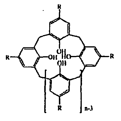
Calix[6]arene HC6 6 H Isopropylcalix[6]arene 3C4 4 i-propyl Tert.-butylcalix[8]arene 4C8 8 t-butyl - The novolacks, which are chemically related to the calixarenes and which are polymeric phenol/formaldehyde condensates which can be both chain-like and ring-like in structure, are also suitable as coating materials.
- Other suitable coating materials are macrocycles such as, for example, lactam macrocycles or ether macrocycles. A great advantage in the synthesis of the lactam macrocycles, as is in the case of the calixarenes, is the great variety of the derivatives available. The diamine group and also the diacid chloride can be replaced readily. A further advantage of this group of substances is that the large number of functional groups gives rise to a broad spectrum of possible host-guest interactions, which means that, as a group of substances, they are candidates for forming good sensor layers. Ether macrocycles can also be assembled in the form of a modular design, as can the lactamamide macrocycles. The phenolic ether groups which are present, the p-systems of the aromatics and any further functionalities in the ring system open up a broad spectrum of host-guest interactions.
- Finally, what are known as dendrimers and polyphenylenes are also suitable as coating materials. The dendrimers are monodisperse oligomeric or polymeric compounds with highly branched monomers which, however, are not crosslinked. This results in a tree-like structure which gives rise to the name (Greek: "dendron" = tree). Three parameters characterize a dendrimer. They are the generation number, the degree of branching and the type of linkage. The generation number indicates the number of monomeric fragments in a.chain which are bound to the central core. The degree of branching describes the number of branchings per monomer per generation. The absolute number of monomer units results from the degree of branching to the power of the generation number. The type of linkage indicates the manner in which each generation is bound to the previous one. The class of the hyper-branched polyphenylenes is very similar to the dendrimers. They are not crosslinked but, in contrast to the dendrimers, are not monodisperse but polydisperse in design. The two parameters, viz. the number-averaged molecular mass Mn and the weight-averaged molecular mass Mw, determine the polydispersity as the Mw/Mn ratio.
- Macrocycles and dendrimers which are suitable as sensor coatings are described in greater detail in the applicant's
WO 02/068953 - Drop-coating, spin-coating, airbrush or electrospray methods can be employed for coating the quartz disks with the preferred materials with selective sensitivity. The electrospray method, where the substance to be applied is dissolved in a suitable solvent which is capable of being electrically polarized, is especially preferred in this context.
Claims (17)
- A method for detecting volatile analytes in air samples from soil, where
a sample material (11) to be analyzed is enclosed in a container (12) which is impermeable to moisture and permeable for the analyte(s) to be detected,
the container is arranged in a sample container (13) filled with ambient air,
an equilibrium concentration of the volatile analyte between the sample material to be analyzed and the air sample is allowed to establish, and the air sample from the sample container is subsequently analyzed wherein
a mass-sensitive sensor (20) with at least one sensor area which is equipped with a surface layer with selective sensitivity for the analyte(s) to be detected is brought into contact with the air sample to be analyzed,
the mass change of the surface layer is detected in the form of electrical signals and the electrical signals are evaluated, where the sensor signal is evaluated at a point in time at which the maximum sensor signal is not yet obtained
wherein the mass-sensitive sensor is purged with ambient air before and/or after each measurement. - A method as claimed in claim 1, wherein the sensor signal is evaluated at a point in time at which between 50 and 99%, preferably between 70 and 90% and especially preferably approximately 80 to 85% of the maximum sensor signal is obtained.
- A method as claimed in claim 1 or 2, wherein, starting with the point in time of measurement, the mean of several sensor signal values which are recorded in short intervals is taken.
- A method as claimed in any of the preceding claims, wherein the humidity content of the air sample is determined.
- A method as claimed in any of the preceding claims, wherein the mass-sensitive sensor is brought into contact with the air sample to be analyzed in the stop-flow method.
- A method as claimed in any of the preceding claims, wherein the mass-sensitive sensor is maintained at an essentially constant temperature during operation.
- A method as claimed in any of the preceding claims for detecting soil disinfectants, in particular MITC, methyl bromide, 1,3-dichloropropene, dimethyl disulfides, iodomethanes.
- A device for detecting volatile analytes in air samples from soil, in particular for carrying out the method according to in any of claims 1 to 7, with
a container (12) which is impermeable to moisture and permeable for the analyte(s) to be detected for enclosing a soil sample material (11) to be analyzed,
a sample container (13) filled with ambient air for housing the container (12),
a mass-sensitive sensor (20) with at least one sensor area (21) which is equipped with a surface layer with selective sensitivity for the analyte(s) to be detected,
means (22) for purging said mass-sensitive sensor (20) with ambient air before and/or after each measurement,
means (22) for bringing the mass-sensitive sensor into contact with the air sample to be analyzed,
detection means for determining the mass change of the surface layer of the sensor area, where the detection means provide a sensor signal which depends on the mass change, and
control means (23) for controlling the detection means and the means (22) for bringing the mass-sensitive sensor into said contact, wherein the control means (23) are arranged such that the sensor signal is evaluated at a point in time at which the maximum sensor signal is not yet obtained. - A device as claimed in claim 8, wherein said means for purging said mass-sensitive sensor and said means for bringing the mass-sensitive sensor into contact with the air sample to be analyzed comprise a pump (22) having a reversible direction of delivery.
- A device as claimed in any of claims 8 or 9, wherein the sensor signal detected at the predetermined point in time amounts to between 50% and 99%, by preference between 70% and 90% and especially preferably approximately 80% to 85% of the maximum sensor signal.
- A device as claimed in any of claims 8 to 10, wherein the sensor area (21) of the mass-sensitive sensor (20) comprises a quartz micro-balance and the detection means comprise an electric resonant circuit in which the quartz micro-balance is arranged.
- A device as claimed in any of claims 8 to 11, wherein the mass-sensitive sensor (20) comprises at least two sensor areas (21) which are coated with the same material, but with different thicknesses.
- A device as claimed in any of claims 8 to 12, wherein the mass-sensitive sensor (20) exhibits sensor areas (21) which are equipped with layers with selectivity for different analytes.
- A device as claimed in any of claims 8 to 8, wherein a humidity sensor for determining the humidity of the air sample is additionally provided.
- A device as claimed in claim 14, wherein the humidity sensor is a separate capacitive sensor unit.
- A device as claimed in any of claims 8 to 15, wherein the selective surface layer comprises a material which is selected from the group consisting of macrocycles, dendrimers, calixarenes and novolacks.
- A device as claimed in any of claims 8 to 16, wherein the device is designed asa portable sensor device (16).
Applications Claiming Priority (2)
| Application Number | Priority Date | Filing Date | Title |
|---|---|---|---|
| DE10318956A DE10318956A1 (en) | 2003-04-26 | 2003-04-26 | Method and device for the detection of volatile analytes in air samples |
| PCT/EP2004/004401 WO2004097390A1 (en) | 2003-04-26 | 2004-04-26 | Method and device for detecting volatile analytes in air samples |
Publications (2)
| Publication Number | Publication Date |
|---|---|
| EP1618370A1 EP1618370A1 (en) | 2006-01-25 |
| EP1618370B1 true EP1618370B1 (en) | 2010-05-12 |
Family
ID=33154454
Family Applications (1)
| Application Number | Title | Priority Date | Filing Date |
|---|---|---|---|
| EP04729431A Expired - Lifetime EP1618370B1 (en) | 2003-04-26 | 2004-04-26 | Method and device for detecting volatile analytes in air samples |
Country Status (10)
| Country | Link |
|---|---|
| US (1) | US7950270B2 (en) |
| EP (1) | EP1618370B1 (en) |
| JP (1) | JP4610549B2 (en) |
| KR (1) | KR20060007397A (en) |
| AT (1) | ATE467831T1 (en) |
| CA (1) | CA2523554A1 (en) |
| DE (2) | DE10318956A1 (en) |
| EC (1) | ECSP056124A (en) |
| ES (1) | ES2344203T3 (en) |
| WO (1) | WO2004097390A1 (en) |
Cited By (1)
| Publication number | Priority date | Publication date | Assignee | Title |
|---|---|---|---|---|
| RU2554623C1 (en) * | 2013-10-31 | 2015-06-27 | Федеральное государственное бюджетное учреждение науки Государственный научный центр Российской Федерации-Институт медико-биологических проблем Российской академии наук (ГНЦ РФ-ИМБП РАН) | Method of estimation and forecast of ageing processes (destruction) of polymer materials according to dynamics of total gas discharge and toxisity of volatile organic compounds (voc) migrating from polymer during ageing and detected by chromatography-mass spectrometry |
Families Citing this family (17)
| Publication number | Priority date | Publication date | Assignee | Title |
|---|---|---|---|---|
| JP2007248323A (en) * | 2006-03-17 | 2007-09-27 | National Institute Of Advanced Industrial & Technology | Molecular detection sensor |
| US20100107735A1 (en) * | 2005-09-22 | 2010-05-06 | Igor Pavlovsky | Gas Sensor |
| DE102006003560B4 (en) * | 2006-01-23 | 2008-01-24 | Union Apparatebaugesellschaft Mbh | Method and apparatus for measuring the concentration of a gas component in a gas mixture |
| JP4973441B2 (en) * | 2007-10-19 | 2012-07-11 | 富士通株式会社 | Atmosphere analyzer and atmosphere analysis method |
| DE102011075005A1 (en) | 2011-04-29 | 2012-10-31 | BSH Bosch und Siemens Hausgeräte GmbH | Vacuum cleaner for cleaning dust in house, has odor sensor that absorbs detected odorant substance on sensor surface, where mass change in odorant substance is detected by odor sensor |
| WO2016194879A1 (en) * | 2015-05-29 | 2016-12-08 | 京セラ株式会社 | Detection method and detection device |
| EP3371583B1 (en) * | 2015-11-06 | 2024-08-14 | Qorvo Us, Inc. | Acoustic resonator devices and fabrication methods providing hermeticity and surface functionalization |
| JP2018155576A (en) * | 2017-03-17 | 2018-10-04 | 太陽誘電株式会社 | Detection element and detection device |
| CN106970202A (en) * | 2017-04-28 | 2017-07-21 | 兰州大学 | A kind of disintegration test comprehensive analysis device and its verification method |
| TWI637360B (en) * | 2017-12-25 | 2018-10-01 | 研能科技股份有限公司 | Method for detecting and warning of volatile organic compounds |
| JP2021528664A (en) * | 2018-07-06 | 2021-10-21 | コーボ ユーエス,インコーポレイティド | Bulk acoustic wave resonator with expanded dynamic range |
| US12078627B2 (en) * | 2019-07-25 | 2024-09-03 | National Institute For Materials Science | Measurement method and measurement device using gas sensor |
| US11493490B2 (en) * | 2019-08-14 | 2022-11-08 | Electronics And Telecommunications Research Institute | Electronic nose apparatus based on spectrum analysis and method of implementing the same |
| KR102815624B1 (en) * | 2019-08-14 | 2025-06-04 | 한국전자통신연구원 | Electronic nose apparatus and method using spectrum analysis |
| CN110927053B (en) * | 2019-12-13 | 2022-07-01 | 深圳市集洁号环保科技有限公司 | Environmental protection material toxic substance volatilization check out test set |
| CN114112776A (en) * | 2021-11-24 | 2022-03-01 | 西安镭博赛因科学仪器有限公司 | Based on closed circulation absorption measurement H in natural gas2Method for S content |
| DE102022120655A1 (en) | 2022-08-16 | 2023-09-28 | J.Schmalz Gmbh | Negative pressure handling device with odor sensor |
Family Cites Families (15)
| Publication number | Priority date | Publication date | Assignee | Title |
|---|---|---|---|---|
| SE418017B (en) * | 1978-06-14 | 1981-04-27 | Bifok Ab | SET TO CONTINUOUSLY DETERMINE DIFFERENT SLOWLY REACTIVE SUBSTANCES QUANTITATIVE USING A SINGLE METCELL |
| NL8803223A (en) * | 1988-12-30 | 1990-07-16 | Flucon Bv | CAPACITIVE MOISTURE SENSOR. |
| US4895017A (en) * | 1989-01-23 | 1990-01-23 | The Boeing Company | Apparatus and method for early detection and identification of dilute chemical vapors |
| JPH0460446A (en) * | 1990-06-29 | 1992-02-26 | Meidensha Corp | Flow cell device |
| JPH0812141B2 (en) * | 1991-12-16 | 1996-02-07 | 日本電信電話株式会社 | Gas discrimination method |
| EP0878711A1 (en) * | 1997-05-15 | 1998-11-18 | Interuniversitair Micro-Elektronica Centrum Vzw | Chemically sensitive sensor comprising arylene alkenylene oligomers |
| US6156578A (en) * | 1998-06-01 | 2000-12-05 | Advanced Technology Materials, Inc. | Quartz crystal microbalance system for detecting concentration of a selected gas component in a multicomponent gas stream |
| US6321588B1 (en) * | 1998-09-11 | 2001-11-27 | Femtometrics, Inc. | Chemical sensor array |
| US6357278B1 (en) * | 1999-08-09 | 2002-03-19 | General Electric Company | Polymer coatings for chemical sensors |
| US6257049B1 (en) * | 1999-08-31 | 2001-07-10 | Lucent Technologies, Inc. | Ambient humidity measurement using microwaves |
| US6405135B1 (en) * | 2000-07-18 | 2002-06-11 | John J. Adriany | System for remote detection and notification of subterranean pollutants |
| JP2002156321A (en) * | 2000-11-22 | 2002-05-31 | Shimadzu Corp | Suspended particulate matter measurement device |
| JP3461167B2 (en) * | 2001-02-07 | 2003-10-27 | 株式会社日立製作所 | Position calculation method and position calculation device |
| DE10109534A1 (en) * | 2001-02-28 | 2002-09-12 | Basf Ag | Method and device for the detection of fuimigants in air samples |
| US6931913B2 (en) * | 2004-01-21 | 2005-08-23 | Constellation Technology Corporation | Chemical agent detector |
-
2003
- 2003-04-26 DE DE10318956A patent/DE10318956A1/en not_active Withdrawn
-
2004
- 2004-04-26 US US10/554,591 patent/US7950270B2/en not_active Expired - Fee Related
- 2004-04-26 DE DE602004027129T patent/DE602004027129D1/en not_active Expired - Lifetime
- 2004-04-26 ES ES04729431T patent/ES2344203T3/en not_active Expired - Lifetime
- 2004-04-26 KR KR1020057020293A patent/KR20060007397A/en not_active Ceased
- 2004-04-26 JP JP2006505272A patent/JP4610549B2/en not_active Expired - Fee Related
- 2004-04-26 EP EP04729431A patent/EP1618370B1/en not_active Expired - Lifetime
- 2004-04-26 CA CA002523554A patent/CA2523554A1/en not_active Abandoned
- 2004-04-26 AT AT04729431T patent/ATE467831T1/en active
- 2004-04-26 WO PCT/EP2004/004401 patent/WO2004097390A1/en not_active Ceased
-
2005
- 2005-10-26 EC EC2005006124A patent/ECSP056124A/en unknown
Non-Patent Citations (1)
| Title |
|---|
| J. REIBEL ET AL.: "Gas analysis with SAW sensor systems", SENSORS AND ACTUATORS, vol. B65, 2000, pages 173 - 175, XP004208630 * |
Cited By (1)
| Publication number | Priority date | Publication date | Assignee | Title |
|---|---|---|---|---|
| RU2554623C1 (en) * | 2013-10-31 | 2015-06-27 | Федеральное государственное бюджетное учреждение науки Государственный научный центр Российской Федерации-Институт медико-биологических проблем Российской академии наук (ГНЦ РФ-ИМБП РАН) | Method of estimation and forecast of ageing processes (destruction) of polymer materials according to dynamics of total gas discharge and toxisity of volatile organic compounds (voc) migrating from polymer during ageing and detected by chromatography-mass spectrometry |
Also Published As
| Publication number | Publication date |
|---|---|
| DE602004027129D1 (en) | 2010-06-24 |
| EP1618370A1 (en) | 2006-01-25 |
| US7950270B2 (en) | 2011-05-31 |
| KR20060007397A (en) | 2006-01-24 |
| CA2523554A1 (en) | 2004-11-11 |
| DE10318956A1 (en) | 2004-11-11 |
| ECSP056124A (en) | 2006-12-20 |
| US20080105029A1 (en) | 2008-05-08 |
| JP4610549B2 (en) | 2011-01-12 |
| JP2006524804A (en) | 2006-11-02 |
| ES2344203T3 (en) | 2010-08-20 |
| WO2004097390A1 (en) | 2004-11-11 |
| ATE467831T1 (en) | 2010-05-15 |
Similar Documents
| Publication | Publication Date | Title |
|---|---|---|
| US7950270B2 (en) | Method and device for detecting volatile analytes in air samples | |
| Penza et al. | Relative humidity sensing by PVA-coated dual resonator SAW oscillator | |
| Di Pietrantonio et al. | A surface acoustic wave bio-electronic nose for detection of volatile odorant molecules | |
| US6360585B1 (en) | Method and apparatus for determining chemical properties | |
| Mirmohseni et al. | Construction of a sensor for determination of ammonia and aliphatic amines using polyvinylpyrrolidone coated quartz crystal microbalance | |
| Chen et al. | The application of CNT/Nafion composite material to low humidity sensing measurement | |
| WO1999018431A1 (en) | Method and apparatus for characterizing materials by using a mechanical resonator | |
| US7459483B2 (en) | Method and device for detecting fumigants in air samples | |
| Penza et al. | SAW chemical sensing using poly-ynes and organometallic polymer films | |
| Cunningham et al. | Design, fabrication and vapor characterization of a microfabricated flexural plate resonator sensor and application to integrated sensor arrays | |
| US7335336B1 (en) | Sensor array using lateral field excited resonators | |
| Holloway et al. | Impedance analysis of the thickness shear mode resonator for organic vapour sensing | |
| JP2001083060A (en) | Polymer coating for chemical sensors | |
| Avramov et al. | Investigations on plasma-polymer-coated SAW and STW resonators for chemical gas-sensing applications | |
| Mirmohseni et al. | Determination of chlorinated aliphatic hydrocarbons in air using a polymer coated quartz crystal microbalance sensor | |
| Rapp et al. | SAGAS: gas analyzing sensor systems based on surface acoustic wave devices-an issue of commercialization of SAW sensor technology | |
| Stedman et al. | Distinguishing chemicals using CMUT chemical sensor array and artificial neural networks | |
| EP2673617B1 (en) | Method and apparatus for detecting and identifying an analyte present in a gaseous medium | |
| Abbas et al. | Multicomponent gas analysis of a mixture of chloroform, octane and toluene using a piezoelectric quartz crystal sensor array | |
| Pinkham et al. | A lateral field excited acoustic wave pesticide sensor | |
| CN105910946B (en) | Sensing system and detection method for VOCs detection | |
| WO2006078255A1 (en) | Method and apparatus for detecting humans and human remains | |
| Mah et al. | Acoustic methods of detection in gas chromatography | |
| Mirmohseni et al. | Application of a quartz crystal nanobalance to the molecularly imprinted recognition of phenylalanine in solution | |
| Potyrailo et al. | Field evaluation of acoustic-wave chemical sensors for monitoring of organic solvents in groundwater |
Legal Events
| Date | Code | Title | Description |
|---|---|---|---|
| PUAI | Public reference made under article 153(3) epc to a published international application that has entered the european phase |
Free format text: ORIGINAL CODE: 0009012 |
|
| 17P | Request for examination filed |
Effective date: 20051025 |
|
| AK | Designated contracting states |
Kind code of ref document: A1 Designated state(s): AT BE BG CH CY CZ DE DK EE ES FI FR GB GR HU IE IT LI LU MC NL PL PT RO SE SI SK TR |
|
| AX | Request for extension of the european patent |
Extension state: AL HR LT LV MK |
|
| DAX | Request for extension of the european patent (deleted) | ||
| 17Q | First examination report despatched |
Effective date: 20070426 |
|
| GRAP | Despatch of communication of intention to grant a patent |
Free format text: ORIGINAL CODE: EPIDOSNIGR1 |
|
| GRAS | Grant fee paid |
Free format text: ORIGINAL CODE: EPIDOSNIGR3 |
|
| GRAA | (expected) grant |
Free format text: ORIGINAL CODE: 0009210 |
|
| AK | Designated contracting states |
Kind code of ref document: B1 Designated state(s): AT BE BG CH CY CZ DE DK EE ES FI FR GB GR HU IE IT LI LU MC NL PL PT RO SE SI SK TR |
|
| REG | Reference to a national code |
Ref country code: GB Ref legal event code: FG4D |
|
| REG | Reference to a national code |
Ref country code: CH Ref legal event code: EP |
|
| REG | Reference to a national code |
Ref country code: IE Ref legal event code: FG4D |
|
| REF | Corresponds to: |
Ref document number: 602004027129 Country of ref document: DE Date of ref document: 20100624 Kind code of ref document: P |
|
| REG | Reference to a national code |
Ref country code: CH Ref legal event code: NV Representative=s name: SCHMAUDER & PARTNER AG PATENT- UND MARKENANWAELTE |
|
| REG | Reference to a national code |
Ref country code: NL Ref legal event code: T3 |
|
| REG | Reference to a national code |
Ref country code: ES Ref legal event code: FG2A Ref document number: 2344203 Country of ref document: ES Kind code of ref document: T3 |
|
| REG | Reference to a national code |
Ref country code: GR Ref legal event code: EP Ref document number: 20100401563 Country of ref document: GR |
|
| PG25 | Lapsed in a contracting state [announced via postgrant information from national office to epo] |
Ref country code: SE Free format text: LAPSE BECAUSE OF FAILURE TO SUBMIT A TRANSLATION OF THE DESCRIPTION OR TO PAY THE FEE WITHIN THE PRESCRIBED TIME-LIMIT Effective date: 20100512 |
|
| REG | Reference to a national code |
Ref country code: HU Ref legal event code: AG4A Ref document number: E008259 Country of ref document: HU |
|
| PG25 | Lapsed in a contracting state [announced via postgrant information from national office to epo] |
Ref country code: SI Free format text: LAPSE BECAUSE OF FAILURE TO SUBMIT A TRANSLATION OF THE DESCRIPTION OR TO PAY THE FEE WITHIN THE PRESCRIBED TIME-LIMIT Effective date: 20100512 Ref country code: FI Free format text: LAPSE BECAUSE OF FAILURE TO SUBMIT A TRANSLATION OF THE DESCRIPTION OR TO PAY THE FEE WITHIN THE PRESCRIBED TIME-LIMIT Effective date: 20100512 |
|
| PG25 | Lapsed in a contracting state [announced via postgrant information from national office to epo] |
Ref country code: PL Free format text: LAPSE BECAUSE OF FAILURE TO SUBMIT A TRANSLATION OF THE DESCRIPTION OR TO PAY THE FEE WITHIN THE PRESCRIBED TIME-LIMIT Effective date: 20100512 Ref country code: CY Free format text: LAPSE BECAUSE OF FAILURE TO SUBMIT A TRANSLATION OF THE DESCRIPTION OR TO PAY THE FEE WITHIN THE PRESCRIBED TIME-LIMIT Effective date: 20100512 |
|
| PG25 | Lapsed in a contracting state [announced via postgrant information from national office to epo] |
Ref country code: EE Free format text: LAPSE BECAUSE OF FAILURE TO SUBMIT A TRANSLATION OF THE DESCRIPTION OR TO PAY THE FEE WITHIN THE PRESCRIBED TIME-LIMIT Effective date: 20100512 Ref country code: PT Free format text: LAPSE BECAUSE OF FAILURE TO SUBMIT A TRANSLATION OF THE DESCRIPTION OR TO PAY THE FEE WITHIN THE PRESCRIBED TIME-LIMIT Effective date: 20100913 Ref country code: DK Free format text: LAPSE BECAUSE OF FAILURE TO SUBMIT A TRANSLATION OF THE DESCRIPTION OR TO PAY THE FEE WITHIN THE PRESCRIBED TIME-LIMIT Effective date: 20100512 |
|
| PG25 | Lapsed in a contracting state [announced via postgrant information from national office to epo] |
Ref country code: CZ Free format text: LAPSE BECAUSE OF FAILURE TO SUBMIT A TRANSLATION OF THE DESCRIPTION OR TO PAY THE FEE WITHIN THE PRESCRIBED TIME-LIMIT Effective date: 20100512 Ref country code: SK Free format text: LAPSE BECAUSE OF FAILURE TO SUBMIT A TRANSLATION OF THE DESCRIPTION OR TO PAY THE FEE WITHIN THE PRESCRIBED TIME-LIMIT Effective date: 20100512 Ref country code: RO Free format text: LAPSE BECAUSE OF FAILURE TO SUBMIT A TRANSLATION OF THE DESCRIPTION OR TO PAY THE FEE WITHIN THE PRESCRIBED TIME-LIMIT Effective date: 20100512 |
|
| PLBE | No opposition filed within time limit |
Free format text: ORIGINAL CODE: 0009261 |
|
| STAA | Information on the status of an ep patent application or granted ep patent |
Free format text: STATUS: NO OPPOSITION FILED WITHIN TIME LIMIT |
|
| 26N | No opposition filed |
Effective date: 20110215 |
|
| REG | Reference to a national code |
Ref country code: DE Ref legal event code: R097 Ref document number: 602004027129 Country of ref document: DE Effective date: 20110214 |
|
| PGFP | Annual fee paid to national office [announced via postgrant information from national office to epo] |
Ref country code: ES Payment date: 20110518 Year of fee payment: 8 Ref country code: FR Payment date: 20110426 Year of fee payment: 8 Ref country code: CH Payment date: 20110412 Year of fee payment: 8 Ref country code: GR Payment date: 20110412 Year of fee payment: 8 |
|
| PGFP | Annual fee paid to national office [announced via postgrant information from national office to epo] |
Ref country code: HU Payment date: 20110414 Year of fee payment: 8 Ref country code: NL Payment date: 20110420 Year of fee payment: 8 Ref country code: BE Payment date: 20110411 Year of fee payment: 8 Ref country code: AT Payment date: 20110412 Year of fee payment: 8 Ref country code: GB Payment date: 20110420 Year of fee payment: 8 |
|
| PGFP | Annual fee paid to national office [announced via postgrant information from national office to epo] |
Ref country code: IT Payment date: 20110422 Year of fee payment: 8 Ref country code: DE Payment date: 20110429 Year of fee payment: 8 |
|
| PG25 | Lapsed in a contracting state [announced via postgrant information from national office to epo] |
Ref country code: MC Free format text: LAPSE BECAUSE OF NON-PAYMENT OF DUE FEES Effective date: 20110430 |
|
| REG | Reference to a national code |
Ref country code: IE Ref legal event code: MM4A |
|
| PG25 | Lapsed in a contracting state [announced via postgrant information from national office to epo] |
Ref country code: IE Free format text: LAPSE BECAUSE OF NON-PAYMENT OF DUE FEES Effective date: 20110426 |
|
| BERE | Be: lapsed |
Owner name: KANESHO SOIL TREATMENT BVBA Effective date: 20120430 |
|
| REG | Reference to a national code |
Ref country code: NL Ref legal event code: V1 Effective date: 20121101 |
|
| REG | Reference to a national code |
Ref country code: CH Ref legal event code: PL |
|
| REG | Reference to a national code |
Ref country code: AT Ref legal event code: MM01 Ref document number: 467831 Country of ref document: AT Kind code of ref document: T Effective date: 20120426 |
|
| GBPC | Gb: european patent ceased through non-payment of renewal fee |
Effective date: 20120426 |
|
| REG | Reference to a national code |
Ref country code: FR Ref legal event code: ST Effective date: 20121228 |
|
| REG | Reference to a national code |
Ref country code: GR Ref legal event code: ML Ref document number: 20100401563 Country of ref document: GR Effective date: 20121102 |
|
| PG25 | Lapsed in a contracting state [announced via postgrant information from national office to epo] |
Ref country code: GB Free format text: LAPSE BECAUSE OF NON-PAYMENT OF DUE FEES Effective date: 20120426 Ref country code: HU Free format text: LAPSE BECAUSE OF NON-PAYMENT OF DUE FEES Effective date: 20120427 Ref country code: CH Free format text: LAPSE BECAUSE OF NON-PAYMENT OF DUE FEES Effective date: 20120430 Ref country code: BE Free format text: LAPSE BECAUSE OF NON-PAYMENT OF DUE FEES Effective date: 20120430 Ref country code: LI Free format text: LAPSE BECAUSE OF NON-PAYMENT OF DUE FEES Effective date: 20120430 Ref country code: AT Free format text: LAPSE BECAUSE OF NON-PAYMENT OF DUE FEES Effective date: 20120426 |
|
| REG | Reference to a national code |
Ref country code: DE Ref legal event code: R119 Ref document number: 602004027129 Country of ref document: DE Effective date: 20121101 |
|
| PG25 | Lapsed in a contracting state [announced via postgrant information from national office to epo] |
Ref country code: FR Free format text: LAPSE BECAUSE OF NON-PAYMENT OF DUE FEES Effective date: 20120430 Ref country code: GR Free format text: LAPSE BECAUSE OF NON-PAYMENT OF DUE FEES Effective date: 20121102 Ref country code: IT Free format text: LAPSE BECAUSE OF NON-PAYMENT OF DUE FEES Effective date: 20120426 |
|
| PG25 | Lapsed in a contracting state [announced via postgrant information from national office to epo] |
Ref country code: NL Free format text: LAPSE BECAUSE OF NON-PAYMENT OF DUE FEES Effective date: 20121101 |
|
| PG25 | Lapsed in a contracting state [announced via postgrant information from national office to epo] |
Ref country code: LU Free format text: LAPSE BECAUSE OF NON-PAYMENT OF DUE FEES Effective date: 20110426 |
|
| REG | Reference to a national code |
Ref country code: ES Ref legal event code: FD2A Effective date: 20130716 |
|
| PG25 | Lapsed in a contracting state [announced via postgrant information from national office to epo] |
Ref country code: ES Free format text: LAPSE BECAUSE OF NON-PAYMENT OF DUE FEES Effective date: 20120427 |
|
| PG25 | Lapsed in a contracting state [announced via postgrant information from national office to epo] |
Ref country code: BG Free format text: LAPSE BECAUSE OF FAILURE TO SUBMIT A TRANSLATION OF THE DESCRIPTION OR TO PAY THE FEE WITHIN THE PRESCRIBED TIME-LIMIT Effective date: 20100812 Ref country code: TR Free format text: LAPSE BECAUSE OF FAILURE TO SUBMIT A TRANSLATION OF THE DESCRIPTION OR TO PAY THE FEE WITHIN THE PRESCRIBED TIME-LIMIT Effective date: 20100512 |
|
| PG25 | Lapsed in a contracting state [announced via postgrant information from national office to epo] |
Ref country code: DE Free format text: LAPSE BECAUSE OF NON-PAYMENT OF DUE FEES Effective date: 20121101 |