EP1617797B1 - Portable raising and lowering device and equipment therefor - Google Patents
Portable raising and lowering device and equipment therefor Download PDFInfo
- Publication number
- EP1617797B1 EP1617797B1 EP04711550A EP04711550A EP1617797B1 EP 1617797 B1 EP1617797 B1 EP 1617797B1 EP 04711550 A EP04711550 A EP 04711550A EP 04711550 A EP04711550 A EP 04711550A EP 1617797 B1 EP1617797 B1 EP 1617797B1
- Authority
- EP
- European Patent Office
- Prior art keywords
- links
- raising
- sections
- arms
- lowering mechanism
- Prior art date
- Legal status (The legal status is an assumption and is not a legal conclusion. Google has not performed a legal analysis and makes no representation as to the accuracy of the status listed.)
- Expired - Lifetime
Links
- 230000007246 mechanism Effects 0.000 claims description 69
- 239000004033 plastic Substances 0.000 claims description 7
- 229920003023 plastic Polymers 0.000 claims description 7
- 239000002184 metal Substances 0.000 claims description 5
- 229910052751 metal Inorganic materials 0.000 claims description 5
- 239000000463 material Substances 0.000 claims description 4
- 230000005484 gravity Effects 0.000 claims description 3
- 238000000926 separation method Methods 0.000 claims description 3
- 241001465754 Metazoa Species 0.000 abstract description 6
- 230000002441 reversible effect Effects 0.000 description 10
- 230000002265 prevention Effects 0.000 description 6
- 238000013461 design Methods 0.000 description 4
- 238000000034 method Methods 0.000 description 4
- 230000009467 reduction Effects 0.000 description 3
- 238000003860 storage Methods 0.000 description 3
- 230000006378 damage Effects 0.000 description 2
- 230000003247 decreasing effect Effects 0.000 description 2
- 230000036961 partial effect Effects 0.000 description 2
- 241000282412 Homo Species 0.000 description 1
- 241000304405 Sedum burrito Species 0.000 description 1
- 230000001154 acute effect Effects 0.000 description 1
- 230000002238 attenuated effect Effects 0.000 description 1
- 238000003287 bathing Methods 0.000 description 1
- 230000008901 benefit Effects 0.000 description 1
- 230000015572 biosynthetic process Effects 0.000 description 1
- 238000005266 casting Methods 0.000 description 1
- 238000003486 chemical etching Methods 0.000 description 1
- 238000000748 compression moulding Methods 0.000 description 1
- 238000004512 die casting Methods 0.000 description 1
- 230000000694 effects Effects 0.000 description 1
- 230000003203 everyday effect Effects 0.000 description 1
- 239000004744 fabric Substances 0.000 description 1
- 230000006872 improvement Effects 0.000 description 1
- 238000002347 injection Methods 0.000 description 1
- 239000007924 injection Substances 0.000 description 1
- 238000001746 injection moulding Methods 0.000 description 1
- 230000010354 integration Effects 0.000 description 1
- 238000005495 investment casting Methods 0.000 description 1
- 238000005304 joining Methods 0.000 description 1
- 238000003754 machining Methods 0.000 description 1
- -1 metal die casting Chemical class 0.000 description 1
- 150000002739 metals Chemical class 0.000 description 1
- 230000004048 modification Effects 0.000 description 1
- 238000012986 modification Methods 0.000 description 1
- 239000002991 molded plastic Substances 0.000 description 1
- 238000000465 moulding Methods 0.000 description 1
- 238000012856 packing Methods 0.000 description 1
- 239000000843 powder Substances 0.000 description 1
- 230000008569 process Effects 0.000 description 1
- 230000002829 reductive effect Effects 0.000 description 1
- 238000005488 sandblasting Methods 0.000 description 1
- 238000007569 slipcasting Methods 0.000 description 1
- 239000000725 suspension Substances 0.000 description 1
- 238000012546 transfer Methods 0.000 description 1
- 238000011282 treatment Methods 0.000 description 1
Images







Classifications
-
- A—HUMAN NECESSITIES
- A61—MEDICAL OR VETERINARY SCIENCE; HYGIENE
- A61G—TRANSPORT, PERSONAL CONVEYANCES, OR ACCOMMODATION SPECIALLY ADAPTED FOR PATIENTS OR DISABLED PERSONS; OPERATING TABLES OR CHAIRS; CHAIRS FOR DENTISTRY; FUNERAL DEVICES
- A61G7/00—Beds specially adapted for nursing; Devices for lifting patients or disabled persons
- A61G7/10—Devices for lifting patients or disabled persons, e.g. special adaptations of hoists thereto
- A61G7/104—Devices carried or supported by
- A61G7/1042—Rail systems
-
- A—HUMAN NECESSITIES
- A61—MEDICAL OR VETERINARY SCIENCE; HYGIENE
- A61G—TRANSPORT, PERSONAL CONVEYANCES, OR ACCOMMODATION SPECIALLY ADAPTED FOR PATIENTS OR DISABLED PERSONS; OPERATING TABLES OR CHAIRS; CHAIRS FOR DENTISTRY; FUNERAL DEVICES
- A61G7/00—Beds specially adapted for nursing; Devices for lifting patients or disabled persons
- A61G7/10—Devices for lifting patients or disabled persons, e.g. special adaptations of hoists thereto
- A61G7/1013—Lifting of patients by
- A61G7/1015—Cables, chains or cords
-
- A—HUMAN NECESSITIES
- A61—MEDICAL OR VETERINARY SCIENCE; HYGIENE
- A61G—TRANSPORT, PERSONAL CONVEYANCES, OR ACCOMMODATION SPECIALLY ADAPTED FOR PATIENTS OR DISABLED PERSONS; OPERATING TABLES OR CHAIRS; CHAIRS FOR DENTISTRY; FUNERAL DEVICES
- A61G7/00—Beds specially adapted for nursing; Devices for lifting patients or disabled persons
- A61G7/10—Devices for lifting patients or disabled persons, e.g. special adaptations of hoists thereto
- A61G7/1049—Attachment, suspending or supporting means for patients
- A61G7/1051—Flexible harnesses or slings
-
- B—PERFORMING OPERATIONS; TRANSPORTING
- B66—HOISTING; LIFTING; HAULING
- B66D—CAPSTANS; WINCHES; TACKLES, e.g. PULLEY BLOCKS; HOISTS
- B66D3/00—Portable or mobile lifting or hauling appliances
- B66D3/12—Chain or like hand-operated tackles with or without power transmission gearing between operating member and lifting rope, chain or cable
- B66D3/16—Chain or like hand-operated tackles with or without power transmission gearing between operating member and lifting rope, chain or cable operated by an endless chain passing over a pulley or a sprocket
-
- B—PERFORMING OPERATIONS; TRANSPORTING
- B66—HOISTING; LIFTING; HAULING
- B66D—CAPSTANS; WINCHES; TACKLES, e.g. PULLEY BLOCKS; HOISTS
- B66D3/00—Portable or mobile lifting or hauling appliances
- B66D3/18—Power-operated hoists
- B66D3/26—Other details, e.g. housings
-
- A—HUMAN NECESSITIES
- A61—MEDICAL OR VETERINARY SCIENCE; HYGIENE
- A61G—TRANSPORT, PERSONAL CONVEYANCES, OR ACCOMMODATION SPECIALLY ADAPTED FOR PATIENTS OR DISABLED PERSONS; OPERATING TABLES OR CHAIRS; CHAIRS FOR DENTISTRY; FUNERAL DEVICES
- A61G2200/00—Information related to the kind of patient or his position
- A61G2200/30—Specific positions of the patient
- A61G2200/34—Specific positions of the patient sitting
-
- A—HUMAN NECESSITIES
- A61—MEDICAL OR VETERINARY SCIENCE; HYGIENE
- A61G—TRANSPORT, PERSONAL CONVEYANCES, OR ACCOMMODATION SPECIALLY ADAPTED FOR PATIENTS OR DISABLED PERSONS; OPERATING TABLES OR CHAIRS; CHAIRS FOR DENTISTRY; FUNERAL DEVICES
- A61G7/00—Beds specially adapted for nursing; Devices for lifting patients or disabled persons
- A61G7/10—Devices for lifting patients or disabled persons, e.g. special adaptations of hoists thereto
- A61G7/1049—Attachment, suspending or supporting means for patients
- A61G7/1061—Yokes
-
- A—HUMAN NECESSITIES
- A61—MEDICAL OR VETERINARY SCIENCE; HYGIENE
- A61G—TRANSPORT, PERSONAL CONVEYANCES, OR ACCOMMODATION SPECIALLY ADAPTED FOR PATIENTS OR DISABLED PERSONS; OPERATING TABLES OR CHAIRS; CHAIRS FOR DENTISTRY; FUNERAL DEVICES
- A61G7/00—Beds specially adapted for nursing; Devices for lifting patients or disabled persons
- A61G7/10—Devices for lifting patients or disabled persons, e.g. special adaptations of hoists thereto
- A61G7/1063—Safety means
- A61G7/1069—Safety means for quick release
Definitions
- This invention relates to portable raising and lowering devices often referred to as hoists, winches or lifts. More particularly, although not exclusively, the invention relates to such devices intended for lifting and optionally transporting human or animal patients who are temporarily or permanently incapacitated. The invention also relates to equipment used as parts of, or for operation of, such devices.
- the present invention relates to raising and lowering devices of all kinds, but it is especially suitable for use in medical or patient care settings for raising and lowering human or animal patients.
- the invention will be described primarily in this context, but it should be noted that the load to be raised or lowered may be of any kind and is generally a load that is difficult, but usually not impossible, for a single person to move without mechanical assistance.
- the load carrying support is often a generally horizontal bar having spaced end sections onto which the load carrying arrangement, such as a patient sling, can be attached.
- the wide separation of the end sections allows for stable attachment of a sling or straps at separated locations.
- an elongated spreader bar makes the device rather bulky and awkward when it has to be transported from on point of use to another, or merely stored.
- devices provided with electric motors, while convenient, are rather heavy and therefore difficult to transport.
- An object of the present invention is to improve raising and lowering devices of the kind to which the present invention relates.
- the load-carrying support is positioned beneath the raising and lowering mechanism, and the arms move in a vertical plane when pivoted from the operating position to the stored position, whereupon the distal end sections are positioned above the raising and lowering mechanism when the arms are in the stored position.
- the attachment element may be connected to the raising and lowering mechanism by an elongated flexible support member, with the raising and lowering mechanism drawing the flexible support member into the mechanism to raise the load- carrying support, and feeding the flexible support member out of the mechanism to lower the load-carrying support.
- the elongated arms and the attachment element are positioned on the device in relation to the raising and lowering mechanism to allow the device to hang vertically from an elevated support to provide without tilting.
- the device of claim 2 wherein the proximal ends of the elongated arms are pivotally attached to a connector member that is itself pivotally attached to the raising and lowering mechanism.
- the raising and lowering mechanism may be operated manually, electrically or via detachable electric motor.
- the mechanism preferably has a rotatable wheel that operates the mechanism when turned, and wherein a flexible element passes around the wheel and forms a dangling loop that is adapted to be grasped and moved by hand.
- the wheel is normally a sprocket wheel having projecting circumferential sprockets, and the flexible element is a chain having recesses for receiving the sprockets.
- the chain comprises two different kinds of links, the links of the two kinds being arranged in alternating sequence and being pivotally attached to each other in a way that allows adjacent links to be oriented to be coplanar or mutually pivoted about axes that are transverse to the chain, and the links of one of the two kinds being wider in a lateral direction of the chain than the links of the other of the two kinds, thereby creating lateral recesses in side edges of the chain at spaced locations along the chain, and wherein the sprockets project in aligned pairs at opposite edges of a circumference of the sprocket wheel in positions adapted to enter and engage with the recesses as the chain passes around the wheel.
- the links of one of the two kinds may be provided with re-entrant sections at each longitudinal end, and wherein the links of the other of the two kinds are elongated and have opposed ends shaped and dimensioned to fit within the re-entrant sections of the links of the one kind. Adjacent links may then be mutually pivotally attached by bosses or pins extending between the links within the re-entrant sections.
- the links of the other kind are shaped such that two links of the one kind attached at opposite ends of a link of the other kind are enabled to pivot into mutual contact without causing detachment of the pins or permanent deformation of the links.
- the device may be provided with both a sprocket and chain drive and a central drive element for powered drive so that the user has the option of manual or electrically driven operation.
- the fact that the links 21 and 22 are of different widths and alternate in sequence along the length of the chain 20 means that the chain has a series of recesses 27 extending at regular intervals inwardly from both side edges 28 of the chain part way through the width of the chain. These recesses 27 are shaped to receive the sprockets 19a and 19b projecting from the sprocket wheel 18 adjacent to each side edge of the wheel (see Figs. 3a and 3b ).
- the shoulders 29 of the larger links 21 abut the sprockets and provide the wheel 18 with a positive drive while allowing the sprockets to disengage the chain without sticking at the point the chain and wheel separate from each other.
- the smaller links 22 are dimensioned to fit between opposing pairs of sprockets 19a and 19b so that the chain lies flat against the cylindrical circumferential surface of the wheel 18.
- the links 21, 22 are preferably made as individual finished components from injection molded plastics, with integrated bosses 25 and holes 26 for connecting the links.
- the links may also be formed by compression molding of plastics, by casting, by machining or by other methods of forming plastics or metals, including metal die casting, investment casting, slip casting or powder injection molding. If the bosses and holes are not made as integral parts at the time of formation of the links, holes may be machined into the links, and the chain may be held together by pins or other fasteners.
- a surface texture may also be added during the molding process by adding a texture to the mold surface, or the links can be given a texture by other methods like sand blasting, drum tumbling or chemical etching.
- the chain also works in the same way as the previous embodiment in that the small links 22' joining the large links 21' form pairs of recesses 27' positioned at regular intervals along the length of the chain and these recesses receive and abut the sprockets 19' of sprocket wheel 18'.
- the engagement of the sprockets and chain is therefore at the two opposed sides of the chain, thus providing an even and secure drive.
- Fig. 8 shows a device 10 not according to the invention having a single spreader bar 7 centrally pivotally mounted on the housing 11.
- the spreader bar 7 In the operating position of the spreader bar 7 (shown in solid lines), the spreader bar hangs downwardly and forms a support for a sling 15 or the like.
- the spreader bar 7 In the stored position (shown in broken lines), the spreader bar 7 is folded upwardly in front of the sprocket wheel 18 and the distal end section 7b forms a graspable handle 16 useful for carrying the device.
- the spreader bar 7 preferably locks in the storage position to facilitate carrying, and can be unlocked when configured for use.
- Figs. 9 and 10 show an alternative embodiment of the device 10 having a pair of spreader bars 7.
- Fig. 9 shows the device in the operating position
- Fig. 10 shows the device in the stored position ready for storage or transportation.
- spreader bars 7 are provided with thickened, reinforced elbow sections 7d that abut firmly together when the arms 7 are in their open position to provide secure support for a sling, such as the one shown at 15 in the earlier embodiment.
- the spreader bars are provided with generally horizontal plastic loops 7e that fit together when the device is in the closed position to form a two parts of a carrying handle 16. In the open position, the loops 7e prevent the straps of the sling from slipping off inadvertently.
- This embodiment is provided with a transparent cover 11 a at the front of the housing 11 that extends over sprocket wheel 18.
- Fig. 12 shows an exploded assembly drawing of one embodiment of the internal components forming a raising and lowering mechanism suitable for use in the present invention, as well as pivotable spreader bars 7 and drive input 1,3.
- the mechanism and spreader bars 7 are supported by a pair of side plates 30 and 32 that may be located within a housing (not shown).
- the plates 30 and 32 have lower attachment points in the form of spreader bar sleeves 52 for the spreader bars 7.
- the spreader bars are pivotally attached to the spreader bar sleeves via attachment pins 53 and friction end caps 54.
- a flexible elongated member 5 e.g. a fabric belt or strap
- the cooperating friction disc 43 and friction plate 44 make it possible to lower a load when desired.
- the friction disc 43 and friction plate 44 together act as a friction clutch normally causing the running gear 45b to rotate when the sprocket wheel 18 rotates.
- One of these elements is attached to the running gear 45b and the other is attached to the remainder of the gear train extending from sprocket wheel 18 to pinion 36.
- mutual slippage between these elements permits the gear train to be moved in the reverse direction even when the running gear 45b is held stationary by the reverse prevention gear.
- the frictional force is made such that it is not exceeded by the torque applied by the maximum load likely to be supported by the device, but is less than the torque that can be applied by a combination of the load and a force exerted by pulling on the flexible element 3 in the reverse (lowering) direction.
- the load can be lowered from a fixed suspended position in a controlled manner by reversal of the rotation of the wheel 18 that causes slippage between elements 43 and 44.
- this lowering mechanism operates essentially without noise and the patient can be lowered to any desired elevation and held there.
- the rollers 191 are pushed in the direction of the narrow lands 192 between the enlargements 193.
- the lands 192 are too narrow to fully receive the rollers 191 and the rollers are causes to bind between the stub axle 190 and the sloping walls 195 of the shell 187, thus preventing further rotation in this direction.
- the springs 194 acting between the rollers 191 and the shell 187 bias the rollers towards the enlargements 193 so that there is less tendency for the rollers to continue to bind when the direction of rotation is changed from that of Fig. 14b to that of Fig. 14a .
- the clutch 60 is preferably incorporated into the sprocket wheel 18 that is driven by the flexible element 3 (e.g. as shown in Fig. 3 ).
- the sprocket wheel 18 has an outer circumferential surface (rim) 61 and an annular wall 62 provided with a central hole 63 that receives a central shaft 64 leading to a gear train of the raising and lowering mechanism (not shown).
- the annular wall 62 acts as a drive input clutch plate as it is driven by the flexible element operated by the user.
- a disc 65 extends peripherally from a central hub 66 that is keyed to the shaft 64 for positive rotation with the shaft.
- the hub extends snugly through the central hole 63 of the annular wall 62 and the annular wall may rotate on the outer surface of the hub.
- the disc 65 forms a driven or follower clutch plate. Both the annular wall 62 and the disc 65 are formed with depressions 67 and 68, respectively, that extend partially through the thickness of the annular wall and drive disc. The depressions 67 and 68 are filled with flat circular magnets 69 and 70, respectively, that lie flush with the adjacent surfaces of the adjacent annular wall or disc.
- a thin plastic separator disc 71 is located between the annular wall 62 and the disc 65. This disc 71 has a central hole 72 that is not keyed to the hub 66 and is free to rotate or to remain stationary.
- the annular wall 62 and disc 65 thus form a pair of rotatable elements that are capable of being rotatable independently of each other but have confronting parts that are magnetically attractive and thus tend to rotate in unison until the attractive force is exceeded.
- the magnets 69 and 70 are preferably positioned such that the magnets 69 in the annular wall 62 all align with the magnets 70 in the disc 65 and face each other on opposite sides of the separator disc 71.
- the magnets are preferably symmetrically arranged around the axis of the central shaft 64 at equal spacings from the axis.
- the magnetic poles are arranged for mutual attraction of the magnets across the separator disc and their magnetic strength is sufficient to hold the disc 65 firmly to the annular wall 62 during normal operation of the equipment. In this case, rotation of the wheel 18 by the flexible element 3 causes equivalent rotation of the disc 65.
- the disc 65 in turn, being keyed to the shaft 64, causes rotation of the shaft and operation of the gear train.
- the torque at which the clutch slips can be varied (if required) by varying the number of magnets 69, 70 and/or by increasing or decreasing the magnetic attraction between the magnets (either by using magnets of different magnetic strength, or by increasing or deceasing the thickness of the separator disc 71).
- a simple way of varying the slippage torque is to remove some of the magnets from one side of the separator disc (e.g. having four magnets on one side and six on the other). It may also be advantageous for some embodiments of the invention to arrange the magnets asymmetrically around the shaft 64 or in a manner than not all magnets confront each other.
- the magnetic clutch fits completely within the outline of the sprocket wheel 18 of the drive input 1, with one of the clutch elements being part of the sprocket wheel itself and the other being a disc fitting within a recess formed within the sprocket wheel.
- the clutch therefore takes up no additional space and its weight is kept to a minimum.
Landscapes
- Health & Medical Sciences (AREA)
- Nursing (AREA)
- Life Sciences & Earth Sciences (AREA)
- Animal Behavior & Ethology (AREA)
- General Health & Medical Sciences (AREA)
- Public Health (AREA)
- Veterinary Medicine (AREA)
- Engineering & Computer Science (AREA)
- Mechanical Engineering (AREA)
- Invalid Beds And Related Equipment (AREA)
- Handcart (AREA)
Abstract
Description
- This invention relates to portable raising and lowering devices often referred to as hoists, winches or lifts. More particularly, although not exclusively, the invention relates to such devices intended for lifting and optionally transporting human or animal patients who are temporarily or permanently incapacitated. The invention also relates to equipment used as parts of, or for operation of, such devices.
- The present invention relates to raising and lowering devices of all kinds, but it is especially suitable for use in medical or patient care settings for raising and lowering human or animal patients. For the sake of convenience, the invention will be described primarily in this context, but it should be noted that the load to be raised or lowered may be of any kind and is generally a load that is difficult, but usually not impossible, for a single person to move without mechanical assistance.
- Incapacitated humans or animals often have to be lifted and transported over short distances for medical procedures or treatments, or merely for everyday functions such as bathing, transfer from a bed to a wheelchair (and vice versa), and the like. Devices intended for lifting and lowering patients in this way are well known and commonly used in homes, offices, extended care facilities, acute care institutions, hospitals, and by home support agencies and the like. Such devices reduce the requirement for heavy lifting by attendants and thus eliminate fatigue and potential injuries for such people and their patients. Early examples of such devices are described in
US Patent No. 788,606 which issued on May 2, 1905 to Robert F. Scott et al. and Australian patent No.623 585 issued to Kenneth William Miles on May 21, 1992 claim 1. - Raising and lowering devices of this kind normally include an attachment element for attaching the device to an elevated support, such as a ceiling track or fixed anchor (e.g. a hook), a raising and lowering mechanism including a gear train capable of handling the weight of a patient, and a load carrying support for attachment of a sling, straps or other carrying arrangement for directly supporting the patient. Devices of this kind may be electrically driven or manually operable. Once the patient has been secured by the carrying arrangement, the raising and lowering mechanism may be operated to raise the patient from a bed or chair. If the attachment element is secured in a ceiling track or on a rail, the patient can be moved from one location to another over short distances while held in the raised position.
- The load carrying support is often a generally horizontal bar having spaced end sections onto which the load carrying arrangement, such as a patient sling, can be attached. The wide separation of the end sections allows for stable attachment of a sling or straps at separated locations. However, the provision of an elongated spreader bar makes the device rather bulky and awkward when it has to be transported from on point of use to another, or merely stored. Moreover, devices provided with electric motors, while convenient, are rather heavy and therefore difficult to transport.
- It would therefore be advantageous to make such devices lighter, smaller and more easily transportable.
- Furthermore, the raising and lowering mechanisms of such devices often include ratchet-like mechanisms (ratchet and pawl arrangements) to hold the patient securely in an elevated position. However, such mechanisms are noisy and can be annoying or disturbing to patients and operators alike.
- There is therefore a need for improvement of raising and lowering devices of this kind.
- An object of the present invention is to improve raising and lowering devices of the kind to which the present invention relates.
- According to the present invention, there is provided a raising and lowering device according to
claim 1. - The arms have elongated sections between the proximal and distal end sections, and the distal end sections are preferably oriented at an angle (e. g. in the range of 45 to 135 degrees, and more preferably 90 degrees) to the elongated sections, thereby forming upward projections from the elongated sections when the arms are in the operating position. This provides hook-like elements to prevent patient carrying arrangements from slipping off the arms. The arms have elongated sections between the proximal and distal end sections, and the proximal end sections are preferably orientated at an angle to the elongated sections, thereby forming upward projections from the elongated sections when the arms are in the operating position.
- Also, the arms have elbow sections where the proximal end sections join the elongated sections, and wherein the elbow sections abut against each other when the arms are in the operating position, thereby preventing downward pivotal motion of the arms.
- Normally, during operation of the device, the load-carrying support is positioned beneath the raising and lowering mechanism, and the arms move in a vertical plane when pivoted from the operating position to the stored position, whereupon the distal end sections are positioned above the raising and lowering mechanism when the arms are in the stored position.
- The attachment element may be connected to the raising and lowering mechanism by an elongated flexible support member, with the raising and lowering mechanism drawing the flexible support member into the mechanism to raise the load- carrying support, and feeding the flexible support member out of the mechanism to lower the load-carrying support.
- Alternatively, the load carrying support may be attached to the raising and lowering mechanism by an elongated flexible support member, and with the raising and lowering mechanism drawing the flexible support member into the mechanism to raise the load-carrying member, and feeding the flexible support member out of the mechanism to lower the load-carrying support. In this case, the load carrying support may include a mechanical linkage connected to the flexible member and carrying the pivotable arms. The proximal end sections of the elongated arms may each be pivotally connected to the mechanical linkage.
- Ideally, the elongated arms and the attachment element are positioned on the device in relation to the raising and lowering mechanism to allow the device to hang vertically from an elevated support to provide without tilting. To assist in this, the device of
claim 2, wherein the proximal ends of the elongated arms are pivotally attached to a connector member that is itself pivotally attached to the raising and lowering mechanism. - The raising and lowering mechanism may be operated manually, electrically or via detachable electric motor. The mechanism preferably has a rotatable wheel that operates the mechanism when turned, and wherein a flexible element passes around the wheel and forms a dangling loop that is adapted to be grasped and moved by hand. The wheel is normally a sprocket wheel having projecting circumferential sprockets, and the flexible element is a chain having recesses for receiving the sprockets. Preferably, the chain comprises two different kinds of links, the links of the two kinds being arranged in alternating sequence and being pivotally attached to each other in a way that allows adjacent links to be oriented to be coplanar or mutually pivoted about axes that are transverse to the chain, and the links of one of the two kinds being wider in a lateral direction of the chain than the links of the other of the two kinds, thereby creating lateral recesses in side edges of the chain at spaced locations along the chain, and wherein the sprockets project in aligned pairs at opposite edges of a circumference of the sprocket wheel in positions adapted to enter and engage with the recesses as the chain passes around the wheel. Adjacent links may be pivotally attached to each other by laterally extending coaxial pairs of bosses or pins extending between the links. At least one of the adjacent links preferably has sockets for receiving and retaining ends of the bosses or pins, and wherein the sockets have cut-outs allowing snap-fitting together or, alternatively, manual separation of the adjacent links by mutual twisting of the adjacent links. The links are made of a rigid plastics material, or alternatively metal, have an outer surface provided with a non-slip finish.
- The links of one of the two kinds may be provided with re-entrant sections at each longitudinal end, and wherein the links of the other of the two kinds are elongated and have opposed ends shaped and dimensioned to fit within the re-entrant sections of the links of the one kind. Adjacent links may then be mutually pivotally attached by bosses or pins extending between the links within the re-entrant sections. The links of the other kind are shaped such that two links of the one kind attached at opposite ends of a link of the other kind are enabled to pivot into mutual contact without causing detachment of the pins or permanent deformation of the links.
- The raising and lowering mechanism preferably includes a one-way roller bearing for an axle and an axle journaled in the bearing, the bearing allowing mutual rotation between the bearing and the axle in one direction consistent with raising of the load, but preventing mutual rotation in an opposite direction consistent with lowering of the load, thereby enabling the load to be raised to any desired elevation by operation of the raising and lowering mechanism and held at the elevation without lowering upon ceasing operation of the raising and lowering mechanism. The raising and lowering mechanisms preferably also includes a magnetic clutch that prevents overload of the raising and lowering mechanism.
-
-
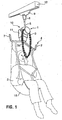
Fig. 1 is a perspective view of one embodiment of the raising and lowering device of the present invention in use lifting a patient; -
Fig. 2 is a front elevation of an alternative device; -
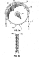
Fig. 3 a is view of the sprocket wheel and flexible drive element of the embodiment ofFig. 1 ; -
Fig. 3b is a side view of the sprocket wheel ofFig. 3a ; -
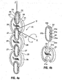
Figs. 4a and 4b are perspective views of the flexible drive element, and links thereof, of the embodiment ofFig. 1 ; -
Fig. 5 shows an alternative form of a flexible drive element and sprocket wheel for use in the devices illustrated in the earlier figures; -
Fig. 6 is a view similar toFig. 2 showing the spreader bars retracted and pivoted to a stored position; -
Figs. 7a and 7b are views similar toFig. 6 of a modified embodiment having shaped carrying handles and also showing the device with the spreader bars in the operating (load carrying) position as well as the stored position; -
Fig. 8 is a side elevation of a device not according to the present invention having a single spreader bar as the load-carrying support; -
Fig. 9 is a perspective view of a further embodiment of the device shown in the operating position; -
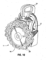
Fig. 10 shows the device ofFig. 9 in the stored position ready for transport; -
Fig. 11 shows and alternative form of the device having spreader bars attached to a pivoted support plate; -
Fig. 12 is an exploded view of one embodiment of a lifting and lowering mechanism according to the present invention; -
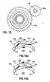
Fig. 13 is a view of parts of the mechanism ofclaim 12 particularly illustrating a one-way roller bearing; -
Figs. 14a and 14b are partial views showing operation of a needle roller race used in the mechanism ofFig. 12 ; -
Fig. 15 is a vertical cross-section of a magnetic clutch employed in a preferred form of the device of the present invention; -
Fig. 16 is a front view of one component of the magnetic clutch ofFig. 15 ; andFig. 17 is a front view of a second component of the magnetic clutch ofFig. 15 . - As shown in
Fig. 1 of the accompanying drawings, one form of the present invention comprises a raising and loweringdevice 10 for ahuman patient 2. Thedevice 10 is provided with a housing 11 (forming a casing enclosing a raising and lowering mechanism), a flexibleelongated member 5, such as a strong flexible but inextensible webbing strap, belt or band, extending from thehousing 11 and secured at an opposite (upper) end to an attachment element 6, such as a hook having a releasable locking tongue, that suspends the device from a slider 9 movable in an elevated fixedtrack 12. The flexibleelongated member 5 can be wound and unwound about a reel component forming part of the raising and lowering mechanism within thehousing 11 of thedevice 10 and is configured such that the induced rotation of the reel component by a drive input in one direction or the other leads to the raising or lowering of thehousing 11. The drive input may be manually powered by means of aflexible element 3, such as a chain, forming an endless dangling loop 3 a that can be rotated by the user in either direction and itself causes rotation of the reel component via a gear train in thehousing 11 that allows a relatively small pulling force to lift the weight of the patient. The device also includes a load-carryingsupport 4 in the form of a pair of elongated arms acting asspreader bars 7 pivotally attached to thehousing 11. The spreader bars are designed for integration with a patient carrying arrangement in the form of asling 15. - As already noted, the device shown in
Fig. 1 is arranged such that the elongatedflexible element 5 raises and lowers thehousing 11, and thereby raises or lowers the load-carryingsupport 4 fixed to thehousing 11. Alternatively, as shown inFig. 2 , the elongatedflexible element 5 may be arranged such that it raises or lowers just the load-carryingsupport 4 while thehousing 11 remains stationary, attached to an elevated support 9 via aconnector 13 of fixed length, e.g. a strap or chain. In this case, the spreader bars 7 may be attached to amechanical linkage 8 that in turn connects the elongatedflexible element 5 to the spreader bars 7. As an alternative to the use of aconnector 13, thehousing 11 may be directly secured to (or integrated as part of) a support, e.g. a support framework movable on casters or the like (not shown), as in this embodiment thehousing 11 does not move vertically during use. - As shown in
Fig. 3a , adrive input 1 for the device may be in the form of asprocket wheel 18 having outwardly projecting circumferential sprockets (teeth) 19 spaced at regular intervals around the periphery of the sprocket wheel. In fact, as shown more clearly inFig. 3b , the sprockets are arranged in transversely alignedpairs sprocket 19a of each pair being provided at the front edge of the wheel rim and the other 19b at the rear edge, spaced apart by a part of the cylindrical circumferential surface of thesprocket wheel 18. Thesprockets flexible element 3 which is in the form of a specialized chain described more fully later. Thesprocket wheel 18 is appropriately connected (see later) such that induced rotation of thedrive input 1 in one direction leads to the raising of theload carrying support 4, and induced rotation in the opposite direction leads to lowering of theload carrying support 4. For example, a clockwise rotation of thedrive input 1 may raise the load carrying support and counter-clockwise rotation of the driveninput 1 may lower theload carrying support 4. - The
drive input 1 may be configured such that when rotation is ceased, the raising or lowering of the device is also ceased, leaving the load-carryingsupport 4 securely fixed at any position. The way in which this is achieved is described later. - As previously described, the
drive input 1 is operated manually by means of an operator pulling down on one side or the other of theflexible element 3. Alternatively, thedrive input 1 may be engaged by means of either a rigid component, such as a handle or crank (not shown) or a turning wheel (not shown). As a further alternative, thedrive input 1 may be operated by a small electrical motor (not shown) forming an integral part of thedevice 10 or, more preferably, forming a separate portable component. For example, a tool similar or identical to an electric screw driver provided with a suitable socket instead of a screw driver blade may be temporarily connected to a central fixed drive element 14 (e.g. a protruding multi-faced nut) on thesprocket wheel 18 and used to turn the wheel in one direction or the other (such electric tools are normally reversible). An arrangement of this kind avoids the need to build an electric drive into the device itself in those cases where power assistance is required, and therefore does not contribute to the weight of the device. Of course, the device may be provided with both a sprocket and chain drive and a central drive element for powered drive so that the user has the option of manual or electrically driven operation. - A preferred embodiment of the
flexible element 3, taking the form of an ergonomically configuredchain 20, is shown in more detail inFig. 4a . The chain consists of rigidindividual links Fig. 4b . Thelinks drive input 1. Thelinks flat bodies 23 and 24 provided with smooth rounded edges to ensure user comfort. A textured surface may also be applied to the links to increase the friction between the user's hand and thechain 20 and thus improve grip strength. Thelinks - The fact that the
links chain 20 means that the chain has a series ofrecesses 27 extending at regular intervals inwardly from both side edges 28 of the chain part way through the width of the chain. Theserecesses 27 are shaped to receive thesprockets sprocket wheel 18 adjacent to each side edge of the wheel (seeFigs. 3a and 3b ). Theshoulders 29 of thelarger links 21 abut the sprockets and provide thewheel 18 with a positive drive while allowing the sprockets to disengage the chain without sticking at the point the chain and wheel separate from each other. Thesmaller links 22 are dimensioned to fit between opposing pairs ofsprockets wheel 18. - As shown in
Fig. 1 , thechain 20 is preferably configured such that it remains a comfortable distance away from thepatient 2 at all times while remaining accessible to the user. If the flexible element has too many degrees of freedom it may swing and hit the patient in the face or head area during use. The avoidance of this inconvenience is an important preferred feature of the device of the present invention because patient comfort is significant to the acceptance of the device. As shown inFig. 4a , this is achieved by endowing the flexible element with the following characteristics: - It can rotate about the X-axis only (transversely to the longitudinal direction of the flexible element).
- It is constrained from rotating to more than a minor amount about the Y axis (twisting laterally about an axis extending at right angles into a face of the chain) and the Z axis (swivelling around the longitudinal axis of the chain when drawn into a straight line).
- In the case of the chain illustrated in
Figs. 4a and 4b , thelarger links 21 havere-entrant sections 21 a at each longitudinal end, and thesmaller links 22 have ends 22c that fit within the re-entrant sections of the larger links. Thelinks device 10. - The
links integrated bosses 25 and holes 26 for connecting the links. The links may also be formed by compression molding of plastics, by casting, by machining or by other methods of forming plastics or metals, including metal die casting, investment casting, slip casting or powder injection molding. If the bosses and holes are not made as integral parts at the time of formation of the links, holes may be machined into the links, and the chain may be held together by pins or other fasteners. A surface texture may also be added during the molding process by adding a texture to the mold surface, or the links can be given a texture by other methods like sand blasting, drum tumbling or chemical etching. - The bosses 25 (or pins) and holes 26 are preferably formed in such a way that the links can be snap-fitted together or separated by hand, e.g. by gripping two adjacent links and firmly twisting them about the Z axis of
Fig. 4a . By this means, the flexible element can be installed on thedevice 10 or removed very easily and the length of the element can be adjusted to the best length for operation. To facilitate this convenient form of attachment or detachment, the links provided withholes 26 to receive thebosses 25 or pins preferably have cut-outs 26a in the material of the walls surrounding the holes that make it easier for the bosses or pins to snap out of, or alternatively to snap into, the holes when desired, while being dimensioned to retain the bosses or pins during normal use of the elongated element. The cut-outs 26a are most preferably positioned such that they are remote from the points of abutment between the bosses or pins and the material surrounding the holes when theflexible element 3 is under tension. However, the cut-outs 26a are positioned directly in the path of the bosses or pins when adjacent links are twisted firmly about axis Z. - As shown in
Fig. 4b , thesmall link 22 hasshallow recesses 22a in the side edges of the major faces. These recesses allow two adjacentlarge links 21 to lie directly one on top of the other, by suitably folding the chain, without interference from or binding of the interveningsmall link 22. Such interference might otherwise cause the links to separate when compressive force is applied to a folded chain, e.g. during packing for storage or transport. - A flexible element of alternative design and a correspondingly modified sprocket wheel are shown in
Fig. 5 . This alternative design is intended to make theflexible element 3 even more comfortable for the user to grip and pull. In this design, large links 21' are approximately cylindrical or of a smoothly rounded "jelly bean" shape. The intervening small links 22' may also be of similar shape or may be generally flat and similar to thelinks 22 of the previous embodiment. The resulting chain 20' feels rather like a smooth thin rope or cord as it is rounded or essentially cylindrical and flexible. However, it still retains the important advantage that adjacent links are freely rotatable only about the "X-axis" as the links are attached in the same manner as the previous embodiment, so that the chain stands clear of the patient's head or body. The chain also works in the same way as the previous embodiment in that the small links 22' joining the large links 21' form pairs of recesses 27' positioned at regular intervals along the length of the chain and these recesses receive and abut the sprockets 19' of sprocket wheel 18'. The engagement of the sprockets and chain is therefore at the two opposed sides of the chain, thus providing an even and secure drive. - In this alternative design, the sprocket wheel 18' is shaped to conform to the shape of the links of the chain. Consequently, the circumference of the wheel has dished
pockets 75 between adjacent pairs of sprockets 19' to accommodate the shape of the large links 21', and generallyflat regions 76 between the sprockets 19' of adjacent pairs to accommodate the shape of the small links 22', assuming that the small links are essentially flat. The resulting effect is that the chain fits snugly around the sprocket wheel 18' with the sprockets 19' fitting securely into and extending through the recesses 27'. - As shown in
Figs. 2 and6 , the spreader bars 7 (elongated rigid arms acting as a load-carrying support are configured so as to be stored in a folded-up position when not in use, e.g. when transporting thedevice 10 from one location to another. This is achieved by providing left and right spreader bars that can rotate in a vertical plane about twopins 17. As shown inFig. 2 the spreader bars haveproximal end sections 7a,distal end sections 7b,elongated sections 7c between the proximal and distal end sections, andelbow sections 7d between the proximal end sections and the elongated sections. Theelbow sections 7d firmly abut against each other when the spreader bars are in the operating position ofFig. 2 . The proximal and distal end sections are set at an angle to the elongated sections, the angle preferably being in the range of 45 to 135 degrees, and normally about 90 degrees. Thedistal end sections 7b angled in this way act as "hooks" that prevent straps of asling 15 or the like from slipping off the spreader bars. - As shown in
Fig. 6 , the distal ends 7b of the spreader bars 7 also function together to form a graspable carrying handle 16 for the device when the spreader bars are rotated to an upright stored position. In this position, thehandle 16 is located above the raising and lowering mechanism within thehousing 11. As shown more particularly inFigs. 7a and 7b , thedistal end sections 7b of the spreader bars may be ergonomically configured so that together they form agraspable handle 16 that conforms to the shape of the operator's hand, which allows for a grip that reduces operator fatigue while transporting thedevice 10. -
Fig. 8 shows adevice 10 not according to the invention having asingle spreader bar 7 centrally pivotally mounted on thehousing 11. In the operating position of the spreader bar 7 (shown in solid lines), the spreader bar hangs downwardly and forms a support for asling 15 or the like. In the stored position (shown in broken lines), thespreader bar 7 is folded upwardly in front of thesprocket wheel 18 and thedistal end section 7b forms agraspable handle 16 useful for carrying the device. Thespreader bar 7 preferably locks in the storage position to facilitate carrying, and can be unlocked when configured for use. -
Figs. 9 and10 show an alternative embodiment of thedevice 10 having a pair of spreader bars 7.Fig. 9 shows the device in the operating position andFig. 10 shows the device in the stored position ready for storage or transportation. In this embodiment, spreader bars 7 are provided with thickened, reinforcedelbow sections 7d that abut firmly together when thearms 7 are in their open position to provide secure support for a sling, such as the one shown at 15 in the earlier embodiment. At thedistal end sections 7b, the spreader bars are provided with generallyhorizontal plastic loops 7e that fit together when the device is in the closed position to form a two parts of a carryinghandle 16. In the open position, theloops 7e prevent the straps of the sling from slipping off inadvertently. This embodiment is provided with atransparent cover 11 a at the front of thehousing 11 that extends oversprocket wheel 18. - In all of the embodiments of the invention, it is desirable to position the load-carrying
support 4, i.e. the spreader bars 7, in relation to the raising and lowering mechanism (i.e. thehousing 11 and its contents), the drive input (i.e.sprocket wheel 18 and drive chain 3), and the attachment element 6, in such a relationship that the overall centre of gravity of the device aligns with the attachment element 6 when the spreader bars are in the operating position and aligned with a vertical plane. As illustrated inFig. 11 (which illustrates yet another embodiment of the invention), this means that the device hangs in a balanced manner without any tilting of thehousing 11 forwardly or rearwardly, or to either side, both before a load (patient) is lifted by the device and during such lifting. To achieve this, the spreader bars may have to be positioned towards the rear or one side of thehousing 11 to compensate for the weight of the sprocket wheel and chain at the front, or any uneven weight of the internal components within thehousing 11. The flexible element 5 (or theconnector 13 ofFig. 2 ) should also be connected to or within thehousing 11 at a point directly above the centre of gravity X when the housing is upright and the spreader bars 7 are in the operating position. - To further ensure that the device hangs in an upright manner, the spreader bars 7 may be pivotally attached to a connector member (suspension plate) 56 that is itself pivotally attached to the
housing 11. This ensures that the spreader bars may remain horizontal in the operating position, even if the housing tilts to one side or the other for some reason, e.g. when the user pulls down on one side or other of theflexible element 3. -
Fig. 12 shows an exploded assembly drawing of one embodiment of the internal components forming a raising and lowering mechanism suitable for use in the present invention, as well as pivotable spreader bars 7 and driveinput spreader bars 7 are supported by a pair ofside plates plates spreader bar sleeves 52 for the spreader bars 7. The spreader bars are pivotally attached to the spreader bar sleeves via attachment pins 53 andfriction end caps 54. A flexible elongated member 5 (e.g. a fabric belt or strap) has a loop at the lower end that passes around apinion 36 and is wound on or off the pinion when the pinion rotates in one direction or the other. Thepinion 36 thus forms a reel component for the flexibleelongated member 5. The pinion passes through aload sheave 33 andball bearing 34 at one end and through aroller bearing 37 andball bearing 35 at the other end. Snap rings 38 and 40 keep these elements in place. Thepinion 36 operates aload gear 39 which cooperates with agear number 2assembly 41 provided with aball bearing 42. The gearing is intended to enable a relatively gentle pull on aflexible element 3 to turnwheel 18 and to wind in the flexibleelongated member 5 even when a considerable weight is suspended from the spreader bars 7. The equipment of the raising and lowering mechanism is completed by a bushing 47, awheel stopper 49 held in place by awheel stopper pin 50 and splitpin 51. - This kind of gear train is normally provided with a ratchet and pawl type mechanism that allows the gears to rotate in one direction only, i.e. in the direction that allows the patient to be lifted. However, such mechanisms are very noisy and distracting, and can be dangerous when used for lifting animals as animals may be startled and panicked by the noise.
- Instead of using a ratchet and pawl mechanism, the present invention incorporates a one-
way roller bearing 46 supporting areverse prevention gear 45a (shown more clearly inFig. 13 ). The reverse prevention gear permanently engages arunning gear 45b forming part of the main gear train. Essentially, thereverse prevention gear 45a rotates with therunning gear 45b as thewheel 18 is used for lifting and this rotation is permitted by the one-way roller bearing 46. When rotation in this direction is stopped, lowering of the load is prevented because the one-way roller bearing 46 does not allow rotation of thereverse prevention gear 45a, which in turn prevents rotation of therunning gear 45b in the reverse direction. Consequently, the load suspended from the spreader bars 7 remains stationary at a fixed elevation. The one-way roller bearing 46 operates essentially without noise and thus eliminates the annoying clatter of a conventional ratchet and pawl mechanism. - Nevertheless, the cooperating
friction disc 43 andfriction plate 44 make it possible to lower a load when desired. Thefriction disc 43 andfriction plate 44 together act as a friction clutch normally causing therunning gear 45b to rotate when thesprocket wheel 18 rotates. One of these elements is attached to therunning gear 45b and the other is attached to the remainder of the gear train extending fromsprocket wheel 18 topinion 36. Thus, mutual slippage between these elements permits the gear train to be moved in the reverse direction even when therunning gear 45b is held stationary by the reverse prevention gear. The frictional force is made such that it is not exceeded by the torque applied by the maximum load likely to be supported by the device, but is less than the torque that can be applied by a combination of the load and a force exerted by pulling on theflexible element 3 in the reverse (lowering) direction. Thus, the load can be lowered from a fixed suspended position in a controlled manner by reversal of the rotation of thewheel 18 that causes slippage betweenelements - Further noise reduction can be achieved, if needed, by making use of gears (at least the main load-bearing gears) made of tough plastics rather than metal.
- The manner in which the one-
way roller bearing 46 operates is shown in the enlarged partial cross-sections ofFigs. 14a and 14b . The roller bearing receives, and is supported by, astub axle 190 that is itself fixed against rotation. The bearing includesneedle rollers 191 forming a needle roller race that surrounds and supports theaxle 190 within a surroundingbearing shell 187 on which thegear 45a is mounted. When rotation of the shell is in the direction shown by the arrows inFig. 14a , therollers 191 are pushed towardsenlargements 193 in the inner surface of theshell 187, so that there is no binding between theaxle 190 and theshell 187. When the direction of rotation is as shown by the arrow inFig. 14b , therollers 191 are pushed in the direction of thenarrow lands 192 between theenlargements 193. Thelands 192 are too narrow to fully receive therollers 191 and the rollers are causes to bind between thestub axle 190 and thesloping walls 195 of theshell 187, thus preventing further rotation in this direction. Thesprings 194 acting between therollers 191 and theshell 187 bias the rollers towards theenlargements 193 so that there is less tendency for the rollers to continue to bind when the direction of rotation is changed from that ofFig. 14b to that ofFig. 14a . - The apparatus shown in
Fig. 12 , apart from thereverse prevention gear 45a and one-way roller bearing 46, as well as the pivotable spreader bars 7 andflexible element 3, is essentially the same as the mechanism of commercially available Kito CB Series Chain Hoist (Model M3) from Kito Corporation of Tokyo, Japan. This known hoist uses a ratchet and pawl mechanism previously discussed. However, other raising and lowering mechanisms well known in the art may be employed, provided they are capable of modification in the manner indicated above. For example, the mechanism ofUS patent 788,606 may be suitable. - It will be noted in the embodiment of
Fig. 12 that the spreader bars 7 extend at right angles to the plane of thesprocket wheel 18 whereas, in other embodiments, the spreader bars 7 extend parallel to the plane of the sprocket wheel 18 (which is the more preferred arrangement). Also, the embodiment ofFig. 12 does not include a magnetic clutch nor the specialized drive chain (described elsewhere in this application). - A preferred form of the
device 10 of the present invention includes a magnetic clutch 60 shown in more detail inFigs. 15 ,16 and17 .Fig. 15 is a cross-section of the assembled clutch andFigs. 16 and 17 show parts thereof. - The clutch 60 is provided in order to prevent damage to the raising and lowering mechanism if an attempt is made to lift a weight that is too heavy for the device. In such a case, the clutch slips harmlessly, preventing lifting from taking place, thus temporarily isolating the raising and lowering mechanism from the
drive input 1. - The clutch 60 is preferably incorporated into the
sprocket wheel 18 that is driven by the flexible element 3 (e.g. as shown inFig. 3 ). Thesprocket wheel 18 has an outer circumferential surface (rim) 61 and anannular wall 62 provided with acentral hole 63 that receives acentral shaft 64 leading to a gear train of the raising and lowering mechanism (not shown). Theannular wall 62 acts as a drive input clutch plate as it is driven by the flexible element operated by the user. Adisc 65 extends peripherally from acentral hub 66 that is keyed to theshaft 64 for positive rotation with the shaft. The hub extends snugly through thecentral hole 63 of theannular wall 62 and the annular wall may rotate on the outer surface of the hub. Thedisc 65 forms a driven or follower clutch plate. Both theannular wall 62 and thedisc 65 are formed withdepressions depressions circular magnets plastic separator disc 71 is located between theannular wall 62 and thedisc 65. Thisdisc 71 has acentral hole 72 that is not keyed to thehub 66 and is free to rotate or to remain stationary. Theannular wall 62 anddisc 65 thus form a pair of rotatable elements that are capable of being rotatable independently of each other but have confronting parts that are magnetically attractive and thus tend to rotate in unison until the attractive force is exceeded. - The
magnets magnets 69 in theannular wall 62 all align with themagnets 70 in thedisc 65 and face each other on opposite sides of theseparator disc 71. The magnets are preferably symmetrically arranged around the axis of thecentral shaft 64 at equal spacings from the axis. The magnetic poles are arranged for mutual attraction of the magnets across the separator disc and their magnetic strength is sufficient to hold thedisc 65 firmly to theannular wall 62 during normal operation of the equipment. In this case, rotation of thewheel 18 by theflexible element 3 causes equivalent rotation of thedisc 65. Thedisc 65 in turn, being keyed to theshaft 64, causes rotation of the shaft and operation of the gear train. However, if the weight on the device reaches an overload cut-off value, slippage may occur between theannular wall 62 and thedisc 65 because the magnetic force holding these two elements together is exceeded. This slippage is facilitated by the presence of theseparator disc 71 which has a low friction surface. The disc is thin enough, however, that the magnetic attraction is not significantly attenuated across the disc. As the magnets are arranged in a symmetrical fashion around the annular wall and drive disc, the magnets will realign after one sixth of a rotation (as there are six magnets in this embodiment). If the weight on the device has been decreased at this time, the magnetic attraction will then cause the annular wall and drive disc to rotate as one. If the weight still exceeds the overload cut-off, these elements will again slip relative to each other until the weight is reduced. The magnetic clutch thus re-sets itself automatically and requires no attention following reduction of weight on the device. - The torque at which the clutch slips can be varied (if required) by varying the number of
magnets shaft 64 or in a manner than not all magnets confront each other. - It will be appreciated from the description above that the magnetic clutch fits completely within the outline of the
sprocket wheel 18 of thedrive input 1, with one of the clutch elements being part of the sprocket wheel itself and the other being a disc fitting within a recess formed within the sprocket wheel. The clutch therefore takes up no additional space and its weight is kept to a minimum.
Claims (26)
- A raising and lowering device provided with a raising and lowering mechanism (10), an attachment element (6) adapted to enable the device to be suspended from an elevated support, and a load-carrying support adapted to support a load to be raised or lowered by said mechanism, characterised in that the load-carrying support (4) comprises a pair of vertically pivotable arms (7) having proximal sections (7a) positioned adjacent each other, elongate sections (7c) extending therefrom said proximal sections (7a) terminating at distal sections (7b), wherein said arms (7) have elbow sections (7d) where said proximal end sections (7a) join said elongated sections (7c), and wherein said elbow sections (7d) abut against each other when said arms (7) are pivoted downward into an operating position, thereby preventing further downward pivotal motion of said arms (7), and a stored position in which the distal end sections (7b) of said pair of arms (7) together form a graspable handle (16) allowing an operator to carry the device.
- The device of claim 1, wherein said distal end sections (7b) of said arms (7) are oriented at an angle to said elongated sections (7c), thereby forming upward projections from said elongated sections (7c) when said arms (7) are in said operating position.
- The device of claim 2, wherein said angle is in the range of 45 to 135 degrees.
- The device of claim 1, wherein said proximal end sections (7a) of said arms (7) are orientated at an angle to said elongated sections (7), thereby forming upward projections from said elongated sections (7c) when said arms (7) are in said operating position.
- The device of claim 1, wherein, during operation of the device, the load-carrying support (4) is positioned beneath said raising and lowering mechanism (10), wherein said arms (7) move in a vertical plane when pivoted from said operating position to said stored position, and wherein said distal end sections (7b) are positioned above said raising and lowering mechanism (10) when said arms (7) are in said stored position.
- The device of claim 1, wherein said attachment element (6) is connected to said raising and lowering mechanism (10) by an elongated flexible support member (5), and wherein said raising and lowering mechanism is adapted to draw said flexible support member (5) into said mechanism (10) to raise said load-carrying support (4), and to feed said flexible support member (5) out of said mechanism (10) to lower said load-carrying support (4).
- The device of claim 6, wherein said load carrying support (4) includes a mechanical linkage (30, 32) connected to said flexible member (5) and carrying said pivotable arms (7).
- The device of claim 7, wherein said proximal end sections of said elongated arms (7a) are each pivotally connected to said mechanical linkage (30, 32).
- The device of claim 1, wherein said elongated arms (7) are positioned on the device in relation to said raising and lowering mechanism (10) to provide said device with an overall centre of gravity that is vertically aligned with said attachment element (6) when said arms (7) are in said operating position and aligned with a vertical plane.
- The device of claim 1, wherein said elongated arms (7) and said attachment element (6) are positioned on the device in relation to said raising and lowering mechanism (10) to allow said device to hang vertically from an elevated support without tilting.
- The device of claim 1, wherein said proximal ends (7a) of said elongated arms (7) are pivotally attached to a connector member (53) that is itself pivotally attached to said raising and lowering mechanism (10).
- The device of claim 1, wherein said raising and lowering mechanism (10) is adapted to be operated manually.
- The device of claim 1, wherein said raising and lowering mechanism (10) has a drive input (1) adapted to be driven by a detachable electric motor.
- The device of claim 1, wherein said raising and lowering mechanism (10) is operated by a drive input (1) comprising a rotatable wheel (18) that operates the mechanism (10) when turned, and wherein a flexible element (3) passes around said wheel (10) and forms a dangling loop that is adapted to be grasped and moved by hand.
- The device of claim 14, wherein said wheel (18) is a sprocket wheel having projecting circumferential sprockets (19), and wherein said flexible element (3) is a chain having recesses for receiving said sprockets (19).
- The device of claim 15, wherein said chain (3) comprises two different kinds of links (21, 22), the links of the two kinds being arranged in alternating sequence along said chain and being pivotally attached to each other in a way that allows adjacent links to be oriented to be coplanar or mutually pivoted about axes that are transverse to the chain, and the links of one of said two kinds being wider in a lateral direction of the chain than the links of the other of said two kinds, thereby creating lateral recesses in side edges of the chain at spaced locations along the chain, and wherein said sprockets project in aligned pairs at opposite edges of a circumference of said sprocket wheel in positions adapted to enter and engage with said recesses as said chain passes around said wheel.
- The device of claim 16, wherein adjacent links (21, 22) are pivotally attached to each other by laterally extending coaxial pairs of bosses or pins (25) extending between said links (21, 22).
- The device of claim 17, wherein at least one of said adjacent links has sockets (26) for receiving and retaining ends of said bosses or pins (25), and wherein said sockets (26) have cut-outs (26a) allowing snap-fitting together or, alternatively, manual separation of said adjacent links (21, 22) by mutual twisting of said adjacent links (21, 22).
- The device of claim 16, wherein said links (21, 22) are made of a rigid plastics material.
- The device of claim 16, wherein said links (21, 22) are made of metal.
- The device of claim 16, wherein said links (21, 22) have outer surface provided with a non-slip finish.
- The device of claim 16, wherein the links of one (21) of said two kinds are provided with re-entrant sections (21 a) at each longitudinal end, and wherein said links of the other (22) of said two kinds are elongated and have opposed ends (22c) shaped and dimensioned to fit within said re-entrant sections (21 a) of the links said one kind (21).
- The device of claim 22, wherein adjacent links (21, 22) are mutually pivotally attached by bosses or pins (25) extending between said links (21, 22) within said re-entrant sections (21 c).
- The device of claim 22, wherein the links of said other kind (22) are shaped such that two links of said one kind (21) attached at opposite ends (22c) of a link of said other kind (22) are enabled to pivot into mutual contact without causing detachment of said pins (25) or permanent deformation of said links (21, 22).
- The device of claim 1, wherein said raising and lowering mechanism (10) includes a one-way roller bearing (191) for an axle and an axle (190) journaled in said bearing, said bearing (191) allowing mutual rotation between said bearing (191) and said axle (190) in one direction consistent with raising of said load, but preventing mutual rotation in an opposite direction consistent with lowering of said load, thereby enabling said load to be raised to any desired elevation by operation of said raising and lowering mechanism (10) and held at said elevation without lowering upon ceasing operation said raising and lowering mechanism (10).
- The device of claim 1, wherein said raising and lowering mechanism (10) is provided with a drive input (1) and a magnetic clutch (60) between said drive input (1) and said raising and lowering mechanism (10) that prevents overload of the raising and lowering mechanism (10) by said drive input (1).
Applications Claiming Priority (2)
| Application Number | Priority Date | Filing Date | Title |
|---|---|---|---|
| US44856403P | 2003-02-18 | 2003-02-18 | |
| PCT/CA2004/000215 WO2004073576A2 (en) | 2003-02-18 | 2004-02-17 | Portable raising and lowering device and equipment therefor |
Publications (2)
| Publication Number | Publication Date |
|---|---|
| EP1617797A2 EP1617797A2 (en) | 2006-01-25 |
| EP1617797B1 true EP1617797B1 (en) | 2012-08-08 |
Family
ID=32908607
Family Applications (1)
| Application Number | Title | Priority Date | Filing Date |
|---|---|---|---|
| EP04711550A Expired - Lifetime EP1617797B1 (en) | 2003-02-18 | 2004-02-17 | Portable raising and lowering device and equipment therefor |
Country Status (3)
| Country | Link |
|---|---|
| US (1) | US7284745B2 (en) |
| EP (1) | EP1617797B1 (en) |
| WO (1) | WO2004073576A2 (en) |
Cited By (1)
| Publication number | Priority date | Publication date | Assignee | Title |
|---|---|---|---|---|
| CN110520377A (en) * | 2017-04-13 | 2019-11-29 | 株式会社开道 | Chain type hoist |
Families Citing this family (31)
| Publication number | Priority date | Publication date | Assignee | Title |
|---|---|---|---|---|
| CA2369668C (en) * | 2002-01-28 | 2010-05-04 | Waverley Glen Systems Ltd. | Personal lift device |
| WO2004073576A2 (en) * | 2003-02-18 | 2004-09-02 | British Columbia Institute Of Technology | Portable raising and lowering device and equipment therefor |
| DE10323175A1 (en) * | 2003-05-22 | 2004-12-23 | TÜV Industrie Service GmbH - TÜV Rheinland Group | test lever |
| US7533869B2 (en) * | 2006-07-20 | 2009-05-19 | Inspire Industries, Llc | Ratcheted lift mechanism |
| DE102006036163A1 (en) * | 2006-08-01 | 2008-02-07 | Stahl Crane Systems Gmbh | Guide pulley with higher chain utilization |
| DE102006036162A1 (en) * | 2006-08-01 | 2008-02-07 | Stahl Crane Systems Gmbh | Chain nut with higher load capacity |
| US7516633B1 (en) * | 2008-01-16 | 2009-04-14 | Ez Trend Technology Co., Ltd. | Electric lock |
| GB2462058B (en) * | 2008-07-14 | 2012-08-08 | Joerns Healthcare Ltd | A spreader bar device |
| CA2649950A1 (en) * | 2009-01-15 | 2010-07-15 | Prism Medical Ltd. | Patient lift device |
| FR2948652B1 (en) * | 2009-07-28 | 2011-09-23 | Airbus Operations Sas | PULLEY AND ROPE MECHANICAL ASSEMBLY AND CHAIN HOIST LIFTING APPARATUS COMPRISING SUCH A MECHANICAL ASSEMBLY |
| CA2774800C (en) * | 2009-09-24 | 2018-11-06 | Arjo Hospital Equipment Ab | Patient lift and coupling therefor |
| US8671475B2 (en) * | 2010-09-14 | 2014-03-18 | Yevgeniy Radzinsky | Apparatus and methods for transferring a patient |
| US9222498B2 (en) | 2011-09-08 | 2015-12-29 | Arjohuntleigh Magog, Inc. | Lifting bar and lifting bar connector |
| ES2664781T3 (en) * | 2011-11-03 | 2018-04-23 | Bardex Corporation | Method and apparatus for manipulating chain segments |
| US9081120B2 (en) | 2012-01-17 | 2015-07-14 | Ion Geophysical Corporation | Apparatus and method for low-tension retrieval of instrumented marine cables |
| US9161873B2 (en) | 2012-06-20 | 2015-10-20 | Jary Edward Tindall | System and method for extricating a victim |
| US9089465B2 (en) * | 2013-02-05 | 2015-07-28 | University Of Delaware | Open area harness system for providing patient mobility |
| US20140250591A1 (en) * | 2013-03-11 | 2014-09-11 | Sports Art Industrial Co., Ltd. | Lifting device for handicapped person |
| US9084709B2 (en) * | 2013-03-14 | 2015-07-21 | Liko Research & Development Ab | Sling bar for patient lift slings |
| US9757297B2 (en) * | 2014-02-03 | 2017-09-12 | Liko Research & Development Ab | Person lift system |
| US20180029204A1 (en) * | 2016-07-29 | 2018-02-01 | Levent Koyuncu | Impact drive adaptor system and method |
| EP3709946B1 (en) * | 2017-11-15 | 2025-10-15 | Amico Mobility Solutions Corporation | Portable patient lift system |
| KR102383883B1 (en) * | 2020-03-31 | 2022-04-07 | 한경환 | Hoist for patient |
| USD989437S1 (en) | 2021-04-06 | 2023-06-13 | Liko Research & Development Ab | Sling bar |
| USD1016302S1 (en) | 2021-04-06 | 2024-02-27 | Liko Research & Development Ab | Sling bar |
| USD989435S1 (en) | 2021-04-06 | 2023-06-13 | Liko Research & Development Ab | Sling bar |
| USD989436S1 (en) | 2021-04-06 | 2023-06-13 | Liko Research & Development Ab | Sling bar |
| CN117404633B (en) * | 2023-11-08 | 2024-07-19 | 惠州市沃生照明有限公司 | Rigidity-changeable desk lamp capable of being stored |
| CN117356528A (en) * | 2023-11-21 | 2024-01-09 | 会东县供销社和茧丝绸产业发展有限公司 | A kind of silkworm raising equipment that is convenient for adjusting the height of the silkworm rack |
| US12546557B2 (en) | 2024-02-14 | 2026-02-10 | Killer Instinct, Inc. | Crossbow crank and related method of use |
| US12566044B2 (en) | 2024-02-14 | 2026-03-03 | Killer Instinct, Inc. | Crossbow de-cocker and related method of use |
Citations (1)
| Publication number | Priority date | Publication date | Assignee | Title |
|---|---|---|---|---|
| WO2004004623A1 (en) * | 2000-09-15 | 2004-01-15 | 614641 N.B. Inc. | A winch assembly for the displacement of a person between a first vertical position and a second vertical position. |
Family Cites Families (21)
| Publication number | Priority date | Publication date | Assignee | Title |
|---|---|---|---|---|
| US756454A (en) * | 1902-08-02 | 1904-04-05 | William Astrup | Awning. |
| US788606A (en) * | 1904-12-10 | 1905-05-02 | Edwin Harrington Son And Company Inc | Hoisting mechanism. |
| US2680203A (en) * | 1952-04-12 | 1954-06-01 | Igor V Zozulin | Permanent magnetic clutch |
| US3351959A (en) * | 1966-04-22 | 1967-11-14 | Bobby G Turpin | Invalid lift |
| FR2171576A5 (en) * | 1972-02-07 | 1973-09-21 | Marinoni | |
| US4815270A (en) | 1980-11-26 | 1989-03-28 | Lapeyre James M | Detachable link chain |
| AU623585B2 (en) * | 1986-03-25 | 1992-05-21 | Kenneth William Miles | Hoist apparatus for disabled people |
| US5007617A (en) * | 1989-08-03 | 1991-04-16 | Vital Kogyo Kabushiki Kaisha | Hand-operated chain block |
| US5125629A (en) * | 1990-08-29 | 1992-06-30 | Vital Kogyo Kabushiki Kaisha | Hand-operated chain block |
| GB2248817A (en) * | 1990-08-31 | 1992-04-22 | Chiltern Medical Developments | Portable lifting apparatus |
| US5374035A (en) * | 1993-06-03 | 1994-12-20 | Santos; Jose C. | Winch with power train, manual operation option, and particular brake assembly |
| DE4332323C2 (en) * | 1993-09-23 | 1995-11-30 | Leybold Ag | Geared motor with an electric motor having a hollow shaft |
| US5427559A (en) | 1994-02-10 | 1995-06-27 | Connector Set Limited Partnership | Chain drive for construction toy system |
| JP3339532B2 (en) | 1994-10-17 | 2002-10-28 | 株式会社シマノ | Spinning reel reverse rotation prevention device |
| NO300614B1 (en) | 1995-04-26 | 1997-06-30 | Actuator As | Adjustment device for lifting suspension |
| JP3584592B2 (en) | 1996-02-07 | 2004-11-04 | 株式会社デンソー | One-way clutch |
| CA2217421C (en) * | 1997-10-03 | 2005-06-07 | Stephane Robert | A person lowering and raising winch assembly |
| US6179270B1 (en) * | 1999-10-12 | 2001-01-30 | Robert Higdon | Portable drive assembly for a manual chain hoist |
| KR100383660B1 (en) | 2000-12-20 | 2003-05-12 | 이필균 | A reverse circulation preventive device of a spinning reel for a fishing |
| WO2004073576A2 (en) * | 2003-02-18 | 2004-09-02 | British Columbia Institute Of Technology | Portable raising and lowering device and equipment therefor |
| US7493996B2 (en) * | 2005-06-10 | 2009-02-24 | Warner Electric Technology Llc | Rotational coupling device |
-
2004
- 2004-02-17 WO PCT/CA2004/000215 patent/WO2004073576A2/en not_active Ceased
- 2004-02-17 EP EP04711550A patent/EP1617797B1/en not_active Expired - Lifetime
- 2004-02-17 US US10/778,119 patent/US7284745B2/en not_active Expired - Fee Related
Patent Citations (1)
| Publication number | Priority date | Publication date | Assignee | Title |
|---|---|---|---|---|
| WO2004004623A1 (en) * | 2000-09-15 | 2004-01-15 | 614641 N.B. Inc. | A winch assembly for the displacement of a person between a first vertical position and a second vertical position. |
Cited By (3)
| Publication number | Priority date | Publication date | Assignee | Title |
|---|---|---|---|---|
| CN110520377A (en) * | 2017-04-13 | 2019-11-29 | 株式会社开道 | Chain type hoist |
| CN110520377B (en) * | 2017-04-13 | 2021-01-22 | 株式会社开道 | chain hoist |
| US11034561B2 (en) | 2017-04-13 | 2021-06-15 | Kito Corporation | Chain block |
Also Published As
| Publication number | Publication date |
|---|---|
| US7284745B2 (en) | 2007-10-23 |
| WO2004073576A2 (en) | 2004-09-02 |
| WO2004073576A3 (en) | 2004-11-25 |
| US20040217078A1 (en) | 2004-11-04 |
| EP1617797A2 (en) | 2006-01-25 |
Similar Documents
| Publication | Publication Date | Title |
|---|---|---|
| US7284745B2 (en) | Portable raising and lowering device and equipment therefor | |
| US6772456B2 (en) | Portable device for patient pullup, rollover, and transfer and methods thereof | |
| US6378148B1 (en) | Patient transfer system | |
| US6289534B1 (en) | Patient lift | |
| US6175973B1 (en) | Stand assist lift | |
| US7240621B2 (en) | Personal lift device | |
| US5737781A (en) | Patient transfer system | |
| KR940003281B1 (en) | Invalid transfer arrangement | |
| US6260218B1 (en) | Traveling lift | |
| JPH11512322A (en) | Patient transfer system | |
| GB2398054A (en) | Powered rope climbing apparatus | |
| WO2000023026A2 (en) | Patient transfer and repositioning system | |
| US20120018689A1 (en) | Patient Lift Device | |
| US8024824B1 (en) | Person lifting apparatus and method | |
| EP3700487B1 (en) | DEVICE FOR CARRYING THE WEIGHT OF A LOAD | |
| US20070130690A1 (en) | Hoisting device | |
| WO1997009896A1 (en) | Patient transfer systems | |
| EP0865245B9 (en) | Patient transfer systems | |
| CN221243312U (en) | Frame type multifunctional nursing shift hanging cabin | |
| WO1993006810A1 (en) | Patient lifting device | |
| CA3079754C (en) | A device for bearing the weight of a load | |
| JP3015243U (en) | Diaper changer for bedridden sick | |
| JP2008168122A (en) | Motor-driven upper half of the body rising assisting machine | |
| JPH07313553A (en) | Easily putting-on and putting-down stretcher | |
| CN118234462A (en) | Personnel transfer device including tiltable double loop safety belt |
Legal Events
| Date | Code | Title | Description |
|---|---|---|---|
| PUAI | Public reference made under article 153(3) epc to a published international application that has entered the european phase |
Free format text: ORIGINAL CODE: 0009012 |
|
| 17P | Request for examination filed |
Effective date: 20051021 |
|
| AK | Designated contracting states |
Kind code of ref document: A2 Designated state(s): AT BE BG CH CY CZ DE DK EE ES FI FR GB GR HU IE IT LI LU MC NL PT RO SE SI SK TR |
|
| AX | Request for extension of the european patent |
Extension state: AL LT LV MK |
|
| DAX | Request for extension of the european patent (deleted) | ||
| 17Q | First examination report despatched |
Effective date: 20070910 |
|
| GRAP | Despatch of communication of intention to grant a patent |
Free format text: ORIGINAL CODE: EPIDOSNIGR1 |
|
| GRAS | Grant fee paid |
Free format text: ORIGINAL CODE: EPIDOSNIGR3 |
|
| GRAA | (expected) grant |
Free format text: ORIGINAL CODE: 0009210 |
|
| AK | Designated contracting states |
Kind code of ref document: B1 Designated state(s): AT BE BG CH CY CZ DE DK EE ES FI FR GB GR HU IE IT LI LU MC NL PT RO SE SI SK TR |
|
| REG | Reference to a national code |
Ref country code: GB Ref legal event code: FG4D |
|
| REG | Reference to a national code |
Ref country code: CH Ref legal event code: EP Ref country code: AT Ref legal event code: REF Ref document number: 569334 Country of ref document: AT Kind code of ref document: T Effective date: 20120815 |
|
| REG | Reference to a national code |
Ref country code: IE Ref legal event code: FG4D |
|
| REG | Reference to a national code |
Ref country code: DE Ref legal event code: R096 Ref document number: 602004038809 Country of ref document: DE Effective date: 20121011 |
|
| REG | Reference to a national code |
Ref country code: NL Ref legal event code: VDEP Effective date: 20120808 |
|
| REG | Reference to a national code |
Ref country code: AT Ref legal event code: MK05 Ref document number: 569334 Country of ref document: AT Kind code of ref document: T Effective date: 20120808 |
|
| PG25 | Lapsed in a contracting state [announced via postgrant information from national office to epo] |
Ref country code: FI Free format text: LAPSE BECAUSE OF FAILURE TO SUBMIT A TRANSLATION OF THE DESCRIPTION OR TO PAY THE FEE WITHIN THE PRESCRIBED TIME-LIMIT Effective date: 20120808 Ref country code: CY Free format text: LAPSE BECAUSE OF FAILURE TO SUBMIT A TRANSLATION OF THE DESCRIPTION OR TO PAY THE FEE WITHIN THE PRESCRIBED TIME-LIMIT Effective date: 20120808 Ref country code: AT Free format text: LAPSE BECAUSE OF FAILURE TO SUBMIT A TRANSLATION OF THE DESCRIPTION OR TO PAY THE FEE WITHIN THE PRESCRIBED TIME-LIMIT Effective date: 20120808 |
|
| PG25 | Lapsed in a contracting state [announced via postgrant information from national office to epo] |
Ref country code: SI Free format text: LAPSE BECAUSE OF FAILURE TO SUBMIT A TRANSLATION OF THE DESCRIPTION OR TO PAY THE FEE WITHIN THE PRESCRIBED TIME-LIMIT Effective date: 20120808 Ref country code: GR Free format text: LAPSE BECAUSE OF FAILURE TO SUBMIT A TRANSLATION OF THE DESCRIPTION OR TO PAY THE FEE WITHIN THE PRESCRIBED TIME-LIMIT Effective date: 20121109 Ref country code: BE Free format text: LAPSE BECAUSE OF FAILURE TO SUBMIT A TRANSLATION OF THE DESCRIPTION OR TO PAY THE FEE WITHIN THE PRESCRIBED TIME-LIMIT Effective date: 20120808 Ref country code: PT Free format text: LAPSE BECAUSE OF FAILURE TO SUBMIT A TRANSLATION OF THE DESCRIPTION OR TO PAY THE FEE WITHIN THE PRESCRIBED TIME-LIMIT Effective date: 20121210 Ref country code: SE Free format text: LAPSE BECAUSE OF FAILURE TO SUBMIT A TRANSLATION OF THE DESCRIPTION OR TO PAY THE FEE WITHIN THE PRESCRIBED TIME-LIMIT Effective date: 20120808 |
|
| PG25 | Lapsed in a contracting state [announced via postgrant information from national office to epo] |
Ref country code: NL Free format text: LAPSE BECAUSE OF FAILURE TO SUBMIT A TRANSLATION OF THE DESCRIPTION OR TO PAY THE FEE WITHIN THE PRESCRIBED TIME-LIMIT Effective date: 20120808 |
|
| PG25 | Lapsed in a contracting state [announced via postgrant information from national office to epo] |
Ref country code: EE Free format text: LAPSE BECAUSE OF FAILURE TO SUBMIT A TRANSLATION OF THE DESCRIPTION OR TO PAY THE FEE WITHIN THE PRESCRIBED TIME-LIMIT Effective date: 20120808 Ref country code: CZ Free format text: LAPSE BECAUSE OF FAILURE TO SUBMIT A TRANSLATION OF THE DESCRIPTION OR TO PAY THE FEE WITHIN THE PRESCRIBED TIME-LIMIT Effective date: 20120808 Ref country code: ES Free format text: LAPSE BECAUSE OF FAILURE TO SUBMIT A TRANSLATION OF THE DESCRIPTION OR TO PAY THE FEE WITHIN THE PRESCRIBED TIME-LIMIT Effective date: 20121119 Ref country code: DK Free format text: LAPSE BECAUSE OF FAILURE TO SUBMIT A TRANSLATION OF THE DESCRIPTION OR TO PAY THE FEE WITHIN THE PRESCRIBED TIME-LIMIT Effective date: 20120808 Ref country code: RO Free format text: LAPSE BECAUSE OF FAILURE TO SUBMIT A TRANSLATION OF THE DESCRIPTION OR TO PAY THE FEE WITHIN THE PRESCRIBED TIME-LIMIT Effective date: 20120808 |
|
| PGFP | Annual fee paid to national office [announced via postgrant information from national office to epo] |
Ref country code: GB Payment date: 20130218 Year of fee payment: 10 Ref country code: FR Payment date: 20130301 Year of fee payment: 10 Ref country code: DE Payment date: 20130219 Year of fee payment: 10 |
|
| PG25 | Lapsed in a contracting state [announced via postgrant information from national office to epo] |
Ref country code: IT Free format text: LAPSE BECAUSE OF FAILURE TO SUBMIT A TRANSLATION OF THE DESCRIPTION OR TO PAY THE FEE WITHIN THE PRESCRIBED TIME-LIMIT Effective date: 20120808 Ref country code: SK Free format text: LAPSE BECAUSE OF FAILURE TO SUBMIT A TRANSLATION OF THE DESCRIPTION OR TO PAY THE FEE WITHIN THE PRESCRIBED TIME-LIMIT Effective date: 20120808 |
|
| PLBE | No opposition filed within time limit |
Free format text: ORIGINAL CODE: 0009261 |
|
| STAA | Information on the status of an ep patent application or granted ep patent |
Free format text: STATUS: NO OPPOSITION FILED WITHIN TIME LIMIT |
|
| 26N | No opposition filed |
Effective date: 20130510 |
|
| PG25 | Lapsed in a contracting state [announced via postgrant information from national office to epo] |
Ref country code: BG Free format text: LAPSE BECAUSE OF FAILURE TO SUBMIT A TRANSLATION OF THE DESCRIPTION OR TO PAY THE FEE WITHIN THE PRESCRIBED TIME-LIMIT Effective date: 20121108 |
|
| REG | Reference to a national code |
Ref country code: DE Ref legal event code: R097 Ref document number: 602004038809 Country of ref document: DE Effective date: 20130510 |
|
| PG25 | Lapsed in a contracting state [announced via postgrant information from national office to epo] |
Ref country code: MC Free format text: LAPSE BECAUSE OF NON-PAYMENT OF DUE FEES Effective date: 20130228 |
|
| REG | Reference to a national code |
Ref country code: CH Ref legal event code: PL |
|
| PG25 | Lapsed in a contracting state [announced via postgrant information from national office to epo] |
Ref country code: LI Free format text: LAPSE BECAUSE OF NON-PAYMENT OF DUE FEES Effective date: 20130228 Ref country code: CH Free format text: LAPSE BECAUSE OF NON-PAYMENT OF DUE FEES Effective date: 20130228 |
|
| REG | Reference to a national code |
Ref country code: IE Ref legal event code: MM4A |
|
| PG25 | Lapsed in a contracting state [announced via postgrant information from national office to epo] |
Ref country code: IE Free format text: LAPSE BECAUSE OF NON-PAYMENT OF DUE FEES Effective date: 20130217 |
|
| REG | Reference to a national code |
Ref country code: DE Ref legal event code: R119 Ref document number: 602004038809 Country of ref document: DE |
|
| GBPC | Gb: european patent ceased through non-payment of renewal fee |
Effective date: 20140217 |
|
| REG | Reference to a national code |
Ref country code: FR Ref legal event code: ST Effective date: 20141031 |
|
| REG | Reference to a national code |
Ref country code: DE Ref legal event code: R119 Ref document number: 602004038809 Country of ref document: DE Effective date: 20140902 |
|
| PG25 | Lapsed in a contracting state [announced via postgrant information from national office to epo] |
Ref country code: GB Free format text: LAPSE BECAUSE OF NON-PAYMENT OF DUE FEES Effective date: 20140217 Ref country code: FR Free format text: LAPSE BECAUSE OF NON-PAYMENT OF DUE FEES Effective date: 20140228 Ref country code: DE Free format text: LAPSE BECAUSE OF NON-PAYMENT OF DUE FEES Effective date: 20140902 |
|
| PG25 | Lapsed in a contracting state [announced via postgrant information from national office to epo] |
Ref country code: TR Free format text: LAPSE BECAUSE OF FAILURE TO SUBMIT A TRANSLATION OF THE DESCRIPTION OR TO PAY THE FEE WITHIN THE PRESCRIBED TIME-LIMIT Effective date: 20120808 |
|
| PG25 | Lapsed in a contracting state [announced via postgrant information from national office to epo] |
Ref country code: LU Free format text: LAPSE BECAUSE OF NON-PAYMENT OF DUE FEES Effective date: 20130217 Ref country code: HU Free format text: LAPSE BECAUSE OF FAILURE TO SUBMIT A TRANSLATION OF THE DESCRIPTION OR TO PAY THE FEE WITHIN THE PRESCRIBED TIME-LIMIT; INVALID AB INITIO Effective date: 20040217 |