EP1617528A1 - Laser oscillator and laser material processing system - Google Patents
Laser oscillator and laser material processing system Download PDFInfo
- Publication number
- EP1617528A1 EP1617528A1 EP04821205A EP04821205A EP1617528A1 EP 1617528 A1 EP1617528 A1 EP 1617528A1 EP 04821205 A EP04821205 A EP 04821205A EP 04821205 A EP04821205 A EP 04821205A EP 1617528 A1 EP1617528 A1 EP 1617528A1
- Authority
- EP
- European Patent Office
- Prior art keywords
- laser
- partition wall
- metal layer
- ptfe
- oscillating apparatus
- Prior art date
- Legal status (The legal status is an assumption and is not a legal conclusion. Google has not performed a legal analysis and makes no representation as to the accuracy of the status listed.)
- Withdrawn
Links
Images



Classifications
-
- H—ELECTRICITY
- H01—ELECTRIC ELEMENTS
- H01S—DEVICES USING THE PROCESS OF LIGHT AMPLIFICATION BY STIMULATED EMISSION OF RADIATION [LASER] TO AMPLIFY OR GENERATE LIGHT; DEVICES USING STIMULATED EMISSION OF ELECTROMAGNETIC RADIATION IN WAVE RANGES OTHER THAN OPTICAL
- H01S3/00—Lasers, i.e. devices using stimulated emission of electromagnetic radiation in the infrared, visible or ultraviolet wave range
- H01S3/02—Constructional details
- H01S3/03—Constructional details of gas laser discharge tubes
- H01S3/036—Means for obtaining or maintaining the desired gas pressure within the tube, e.g. by gettering, replenishing; Means for circulating the gas, e.g. for equalising the pressure within the tube
Definitions
- the present invention relates to a laser oscillating apparatus and a laser working machine using a centrifugal blower.
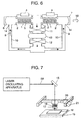
- Fig.6 shows an example of an outline constitution of a laser oscillating apparatus of a background art.
- the laser oscillating apparatus of the background art will be explained in reference to Fig.6.
- the laser oscillating apparatus of the background art includes electrodes 2, 3 at a periphery of discharge tube 1 constituted by a dielectric member of glass or the like. Electrodes 2, 3 are respectively connected with power sources 4. Discharge space 5 is formed at inside of discharge tube 1 interposed by electrodes 2, 3. Further, a total reflection mirror and partial reflection mirror 7 are provided. Laser beam 58 is outputted from partial reflection mirror 7. Arrow mark 9 designates a direction in which laser gas flows. Further, heat exchangers 11, 12 for lowering a temperature of the laser gas, a temperature of which rises by discharge in discharge space 5 and by operation of a centrifugal blower, are provided. Laser gas is circulated by using blowing means 43. As blowing means 43, for example, a centrifugal blower, mentioned later, or the like is used. Laser gas flow path 10 and discharge tube 1 are connected by laser gas introducing portion 14.
- Fig.7 shows an example of an outline constitution of a laser working machine in the background art.
- the laser working machine of the background art will be explained in reference to Fig.7.
- Laser beam 58 outputted from the laser oscillating apparatus shown in Fig. 6 is reflected by reflecting mirror 15 and is guided to a vicinity of work 16.
- Laser beam 58 is converged into a high density energy beam by condenser lens 18 provided at inside of torch 17 and irradiated to work 16 to process the work 16.
- Work 16 is fixed on work table 19 and a predetermined shape is obtained by moving torch 17 relative to work 16 by X axis motor 20 or Y axis motor 21.
- Fig.8 shows a structure of a periphery of a centrifugal blower in the laser oscillating apparatus.
- Motor 22 in centrifugal blower 43 includes motor rotor 22a in a direction orthogonal to a gravitational force direction (arrow mark G direction), and includes motor stator 22b on a lower side in the gravitational force direction (arrow mark G) (that is, lower side of drawing).
- a front end of shaft 29 coupled with rotor 22a is provided with blade wheel 23 and diffuser 24.
- Laser gas is sucked from suction port 25 from an upper direction in the gravitational force direction and is provided with kinetic energy by a centrifugal force by rotation of blade wheel 23. Thereafter, the kinetic energy is converted into pressure by diffuser 24 and a gas having pressure about 1.5 times as much as that of the suction port 25 is delivered from delivery port 26.
- Oil 27 is contained at a portion of casing 31 containing motor 22 below centrifugal blower 43 and is used for lubricating bearing 28 and cooling rotor 22a.
- partition wall portion 50 is provided to separate motor chamber 54 and gas circulating chamber 35.
- a clearance (clearance 57 as shown by Fig.9) of several 100 ⁇ m is provided between partition wall portion 50 and shaft 29 to thereby construct a constitution of not hampering rotation of the shaft.
- a pressure of motor chamber 54 is constituted by a pressure lower than that of gas circulating chamber 35.
- a path reaching vacuum pump 32 from motor chamber 54 is provided with electromagnetic valve 33, which is opened and closed as needed.
- Fig. 9 shows a detailed structure of partition wall portion 50. Clearance 57 of several 100 ⁇ m is provided between shaft 29 and metal seal 36 and a constant amount of laser gas always flows to clearance 57. By the always flowing laser gas, invasion of oil mist from motor chamber 54 to gas circulating chamber 35 can be prevented.
- Laser gas flowing through clearance 57 between shaft 29 and metal seal 36 is exhausted to outside as it is by vacuum pump 32 and therefore, it is necessary to supply an exhausted amount of laser gas to gas circulating chamber 35 by other route. This constitutes a consumption amount per unit time of laser gas in the laser oscillating apparatus and the laser working machine to share a large weight in running cost.
- clearance 57 in order to reduce the laser gas consumption amount.
- laser gas passing through the clearance 57 includes sputtering particles by laser gas discharge and small unavoidable particles which are generated in a component assembling step.
- clearance 57 is narrowed to about several 10 ⁇ m, there is a possibility of deteriorating reliability by clogging clearance 57 with the particles.
- JP-A-2004-207467 discloses an example of using a PTFE material at a partition wall portion and forming a minimum clearance by wearing PTFE by forcibly bringing the PTFE material and a rotating shaft into contact with each other, a high accuracy is difficult to ensure by the method.
- a laser oscillating apparatus of the invention is an apparatus including discharging means for exciting a laser medium, blowing means for blowing a laser gas, and a laser gas path for connecting the discharging means and the blowing means, and is a laser oscillating apparatus characterized in that the blowingmeans is blowingmeans including a shaft portion provided with a blade wheel portion at a front end thereof, a driving portion for rotating the shaft portion and a partition wall portion for separating the blade wheel portion and the driving portion, and a surface of the partition wall portion is provided with a metal layer dispersing precipitated polytetrafluoroethylene (PTFE).
- PTFE metal layer dispersing precipitated polytetrafluoroethylene
- a highly reliable laser oscillating apparatus and a highly reliable laser working machine capable of reducing running cost by restraining a gas consumption amount and capable of being used stably over a long period of time can be realized.
- Fig. 1 shows an example of an outline constitution of laser oscillating apparatus 101 according to the embodiment and a detailed explanation will be given thereof in reference to Fig.1 as follows.
- Laser oscillating apparatus 101 includes discharge tube 1 made by a dielectric member and electrodes 2, 3 provided at a periphery of discharge tube 1. Electrodes 2, 3 are respectively connected to power source 4. A region interposed between electrodes 2, 3 is discharge space 5 at inside of discharge tube 1. Further, total reflection mirror 6 and partial reflection mirror 7 are provided and laser beam 8 is emitted from partial reflection mirror 7. Arrow mark 9 designates a direction in which laser gas flows.
- heat exchangers 11 and 12 for lowering a temperature of laser gas, a temperature of which rises by discharge in discharge space 5 and driving a centrifugal blower, are provided and as blowing means 13 for circulating laser gas, for example, a centrifugal blower or the like, mentioned later, is used.
- Laser gas flowpath 10 and discharge tube 1 are connected by laser gas introducing portion 14.
- Fig.2 shows a structure of a periphery of a centrifugal blower in the laser oscillating apparatus.
- Motor 22 provided by centrifugal blower 13 in a gravitational force direction is constituted by motor stator 22b and motor rotor 22a.
- Motor 22 includes rotor 22a in a direction orthogonal to the gravitational force direction (arrow mark G direction) and includes motor stator 22b on a lower side in the gravitational force direction (arrow mark G direction) (that is, lower side of drawing).
- a front end of shaft 29 coupled with rotor 22a is provided with blade wheel 23 and diffuser 24.
- Laser gas 110 is sucked from suction port 25 from an upper direction in the gravitational force direction and is provided with kinetic energy by a centrifugal force by rotation of blade wheel 23. Thereafter, the kinetic energy is converted into pressure by diffuser 24 and the gas having a pressure about 1.5 times as much as that of suction port 25 is delivered from delivery port 26.
- Oil 27 is contained at a portion of casing 31 containing motor 22 at a lower portion of centrifugal blower 13, and is used for lubricating bearing 28 and cooling rotor 22a.
- partition wall portion 30 is provided in order to restrain oil mist from invading a laser gas circulating portion (laser gas flow path 10) and separates motor chamber 34 and gas circulating chamber 35.
- partition wall portion 30 is constituted by metal seal 36 and shaft 29 at a vicinity of metal seal 36. Clearance 37 is provided between metal seal 29 and shaft 29 and is constructed by a constitution of not hampering rotation of the shaft.
- clearance 37 is included in partition wall portion 30 and therefore, normally, oil mist passes through the clearance and invades gas circulating chamber 35 from motor chamber 34 by vacuum diffusion.
- the constant amount of laser gas always flows at clearance 37 between shaft 29 and metal seal 36. That is, since laser gas always flows through clearance 37, oil mist can be prevented from invading gas circulating chamber 35 from motor chamber 34.
- shaft 29 is made of stainless steel and metal seal 36 is constituted by a copper containing material.
- surfaces of shaft 29 and metal seal 36 are coated by coating 38 of nickel plating including polytetrafluoroethylene (PTFE) particles.
- nickel plating including PTFE particles refers to nickel Teflon plating by electroless plating for example and PTFE particles are uniformly dispersed and precipitated in a skin film plated by nickel.
- Teflon is a registered trade mark of PTFE by DuPont Corporation
- the surface of metal seal 36 and the surface of shaft 29 are coated by nickel plating including PTFE particles, in contrast to a normal metal surface which is not subjected to the above-described coating processing, the surfaces are very excellent in a sliding property. Therefore, even when a foreign material invades clearance 37, a possibility of bringing about a drawback of clogging the clearance when the foreign material invades or the like can be reduced. Further, the surface subjected to nickel Teflon plating by electroless plating is provided with excellent water repellency. Therefore, there is also achieved an effect of reducing adherence of a particularly wet foreign material to the surface of coating 38 in clearance 37.
- clearance 37 can be made to be infinitely smaller than several 100 ⁇ m of the background art in a range permitted by a machining accuracy. Therefore, an amount of laser gas passing through clearance 37 can be reduced and a significant reduction in running cost can be achieved by restraining a laser gas consumption amount per unit time. Specifically, clearance 37 can be reduced to 20 ⁇ m. Even in this case, high speed rotation (700Hz) of shaft 29 can be permitted.
- resin is included in the metal material by 15% or more and 60% or less. Therefore, a dimensional accuracy can be ensured by the metal material and the sliding property can be ensured by the resin material. That is, the dimensional accuracy and the sliding property can be made to be compatible with each other.
- a constitution of including PTFE, which has high sliding property among resins, in electroless plating whose major component is nickel is excellent in obtaining compatibility of the dimensional accuracy and the sliding property.
- the generated gas is mixed into laser gas to deteriorate a laser characteristic.
- Nickel and PTFE are preferably in view of reducing occurrence of such a problem.
- Fig.4 shows volume content, a dynamic friction coefficient and an exfoliation performance of PTFE included in nickel plating. It is found that when the volume content of PTFE is less than 15%, the dynamic friction coefficient is increased and a sufficient sliding performance cannot be ensured. On the other hand, when the volume content of PTFE is larger than 60%, separation of PTFE particles from the plated metal is brought about and coating per se cannot be ensured. Therefore, it is preferable that the volume content of PTFE is equal to or larger than 15% and equal to or smaller than 60%.
- Fig.5 shows an example of an outline constitution of a laser working machine according to the embodiment.
- the laser working machine will be explained in reference to Fig.5.
- Laser beam 8 outputted from the laser oscillating apparatus explained in reference to Fig.1 is reflected by reflecting mirror 15 and is guided to a vicinity of work 16.
- Laser beam 8 is converged into a high density energy beam by condenser lens 18 provided at inside of torch 17 and is irradiated to work 16 to process work 16.
- Work 16 is fixed on work table 19 and torch 17 in which X axis motor 20 or Y axis motor 21 is controlled by a numerical control apparatus (not illustrated) is moved relative to work 16 to thereby process the work in a predetermined shape. Further, a predetermined shape may be processed by controlling to drive work table 19 by a numerical control apparatus.
- a predetermined shape may be worked by controlling to drive both of torch 17 and work table 19 by a numerical control apparatus.
- the laser oscillating apparatus and the laser working machine of the invention can provide a highly reliable laser oscillating apparatus and a highly reliable laser working machine which can reduce running cost particularly by restraining a gas consumption amount and can stably be used over a long period of time and are industrially useful.
Landscapes
- Physics & Mathematics (AREA)
- Electromagnetism (AREA)
- Engineering & Computer Science (AREA)
- Plasma & Fusion (AREA)
- Optics & Photonics (AREA)
- Lasers (AREA)
- Structures Of Non-Positive Displacement Pumps (AREA)
Abstract
Description
- The present invention relates to a laser oscillating apparatus and a laser working machine using a centrifugal blower.
- Fig.6 shows an example of an outline constitution of a laser oscillating apparatus of a background art. The laser oscillating apparatus of the background art will be explained in reference to Fig.6.
- The laser oscillating apparatus of the background art includes
electrodes discharge tube 1 constituted by a dielectric member of glass or the like.Electrodes power sources 4.Discharge space 5 is formed at inside ofdischarge tube 1 interposed byelectrodes partial reflection mirror 7 are provided.Laser beam 58 is outputted frompartial reflection mirror 7.Arrow mark 9 designates a direction in which laser gas flows. Further,heat exchangers discharge space 5 and by operation of a centrifugal blower, are provided. Laser gas is circulated by using blowing means 43. As blowing means 43, for example, a centrifugal blower, mentioned later, or the like is used. Lasergas flow path 10 anddischarge tube 1 are connected by lasergas introducing portion 14. - Fig.7 shows an example of an outline constitution of a laser working machine in the background art. The laser working machine of the background art will be explained in reference to Fig.7.
-
Laser beam 58 outputted from the laser oscillating apparatus shown in Fig. 6 is reflected by reflectingmirror 15 and is guided to a vicinity ofwork 16.Laser beam 58 is converged into a high density energy beam bycondenser lens 18 provided at inside oftorch 17 and irradiated to work 16 to process thework 16.Work 16 is fixed on work table 19 and a predetermined shape is obtained by movingtorch 17 relative to work 16 byX axis motor 20 orY axis motor 21. - Fig.8 shows a structure of a periphery of a centrifugal blower in the laser oscillating apparatus.
-
Motor 22 incentrifugal blower 43 includesmotor rotor 22a in a direction orthogonal to a gravitational force direction (arrow mark G direction), and includesmotor stator 22b on a lower side in the gravitational force direction (arrow mark G) (that is, lower side of drawing). A front end ofshaft 29 coupled withrotor 22a is provided withblade wheel 23 anddiffuser 24. Laser gas is sucked fromsuction port 25 from an upper direction in the gravitational force direction and is provided with kinetic energy by a centrifugal force by rotation ofblade wheel 23. Thereafter, the kinetic energy is converted into pressure bydiffuser 24 and a gas having pressure about 1.5 times as much as that of thesuction port 25 is delivered fromdelivery port 26. -
Oil 27 is contained at a portion ofcasing 31 containingmotor 22 belowcentrifugal blower 43 and is used for lubricatingbearing 28 andcooling rotor 22a. When oil mist generated fromoil 27 invades laser gas circulated byblade wheel 23, a purity of laser gas is reduced to bring about a significant drawback in laser oscillation. Hence, in order to restrain oil mist from invading a laser gas circulating portion (that is, laser gas flow path 10),partition wall portion 50 is provided toseparate motor chamber 54 andgas circulating chamber 35. A clearance (clearance 57 as shown by Fig.9) of several 100µm is provided betweenpartition wall portion 50 andshaft 29 to thereby construct a constitution of not hampering rotation of the shaft. - As described above, the clearance of several 100µm is present at
partition wall portion 50 and therefore, oil mist invadesgas circulating chamber 35 frommotor chamber 54 by passing the clearance by vacuum diffusion. In order to prevent this, by always exhausting a constant amount of gas frommotor chamber 54 by usingvacuum pump 32, a pressure ofmotor chamber 54 is constituted by a pressure lower than that ofgas circulating chamber 35. A path reachingvacuum pump 32 frommotor chamber 54 is provided withelectromagnetic valve 33, which is opened and closed as needed. - Fig. 9 shows a detailed structure of
partition wall portion 50.Clearance 57 of several 100µm is provided betweenshaft 29 andmetal seal 36 and a constant amount of laser gas always flows toclearance 57. By the always flowing laser gas, invasion of oil mist frommotor chamber 54 togas circulating chamber 35 can be prevented. - Laser gas flowing through
clearance 57 betweenshaft 29 andmetal seal 36 is exhausted to outside as it is byvacuum pump 32 and therefore, it is necessary to supply an exhausted amount of laser gas togas circulating chamber 35 by other route. This constitutes a consumption amount per unit time of laser gas in the laser oscillating apparatus and the laser working machine to share a large weight in running cost. - Therefore, it is a serious problem in view of reducing running cost how to reduce the consumption amount of laser gas per unit time. It is necessary to narrow
clearance 57 in order to reduce the laser gas consumption amount. However, generally, laser gas passing through theclearance 57 includes sputtering particles by laser gas discharge and small unavoidable particles which are generated in a component assembling step. Whenclearance 57 is narrowed to about several 10µm, there is a possibility of deteriorating reliability byclogging clearance 57 with the particles. - In the case of the background art of JP-A-10-184593, it is only disclosed to simply specify a shape and a dimension of
metal seal 36 with regard toclearance 57 and it is not pointed out to prevent clogging of foreign matters as a problem. - Further, although JP-A-2004-207467 discloses an example of using a PTFE material at a partition wall portion and forming a minimum clearance by wearing PTFE by forcibly bringing the PTFE material and a rotating shaft into contact with each other, a high accuracy is difficult to ensure by the method.
- A laser oscillating apparatus of the invention is an apparatus including discharging means for exciting a laser medium, blowing means for blowing a laser gas, and a laser gas path for connecting the discharging means and the blowing means, and is a laser oscillating apparatus characterized in that the blowingmeans is blowingmeans including a shaft portion provided with a blade wheel portion at a front end thereof, a driving portion for rotating the shaft portion and a partition wall portion for separating the blade wheel portion and the driving portion, and a surface of the partition wall portion is provided with a metal layer dispersing precipitated polytetrafluoroethylene (PTFE).
- By the constitution, a highly reliable laser oscillating apparatus and a highly reliable laser working machine capable of reducing running cost by restraining a gas consumption amount and capable of being used stably over a long period of time can be realized.
-
- Fig.1 is an outline constitution view of a laser oscillating apparatus according to an embodiment of the invention.
- Fig.2 is a view of a structure of a centrifugal blower portion of the laser oscillating apparatus according to the embodiment.
- Fig.3 is a view of a structure of a partition wall portion of the laser oscillating apparatus according to the embodiment.
- Fig.4 is a diagram showing volume content, dynamic friction coefficient and exfoliation performance of polytetrafluoroethylene included in nickel plating according to the embodiment.
- Fig. 5 is an outline constitution view of a laser working machine according to the embodiment.
- Fig.6 is an outline constitution view of a laser oscillating apparatus of a background art.
- Fig.7 is an outline constitution view of a laser working machine according to a background art.
- Fig.8 is a view of a structure of a centrifugal blower portion of the laser oscillating apparatus of the background art.
- Fig. 9 is a view of a structure of a partition wall portion of the laser oscillating apparatus and the laser working machine of the background art.
-
- 1
- discharge tube
- 2,3
- electrodes
- 4
- power source
- 5
- discharge space
- 6
- total reflection mirror
- 7
- partial reflection mirror
- 8
- laser beam
- 9
- laser gas flowing direction
- 10
- laser gas flow path
- 11, 12
- .heat exchangers
- 13
- centrifugal blower
- 14
- laser gas introducing portion
- 15
- reflecting mirror
- 16
- work
- 17
- torch
- 18.
- convdenser lens
- 19
- worktable
- 20
- X axis motor
- 21
- Y axis motor
- 22
- motor
- 22a
- motor rotor
- 22b
- motor stator
- 23
- blade wheel
- 24
- difuser
- 25
- suction port
- 26
- delivery port
- 27
- oil
- 28
- bearing
- 29
- shaft
- 30
- partition wall portion
- 31
- casing
- 32
- vacuum pump
- 33
- electromagnetic valve
- 34
- motor chamber
- 35..
- gas circulating chamber
- 36
- metal seal
- 37
- clearance
- 38
- coating
- 101
- laser oscillating apparatus
- 110
- laser gas
- An embodiment of the invention will be explained in reference to the drawings.
- Fig. 1 shows an example of an outline constitution of
laser oscillating apparatus 101 according to the embodiment and a detailed explanation will be given thereof in reference to Fig.1 as follows. -
Laser oscillating apparatus 101 includesdischarge tube 1 made by a dielectric member andelectrodes discharge tube 1.Electrodes power source 4. A region interposed betweenelectrodes discharge space 5 at inside ofdischarge tube 1. Further,total reflection mirror 6 andpartial reflection mirror 7 are provided andlaser beam 8 is emitted frompartial reflection mirror 7.Arrow mark 9 designates a direction in which laser gas flows. - Further,
heat exchangers discharge space 5 and driving a centrifugal blower, are provided and as blowing means 13 for circulating laser gas, for example, a centrifugal blower or the like, mentioned later, is used.Laser gas flowpath 10 anddischarge tube 1 are connected by lasergas introducing portion 14. - Next, Fig.2 shows a structure of a periphery of a centrifugal blower in the laser oscillating apparatus.
-
Motor 22 provided bycentrifugal blower 13 in a gravitational force direction (arrow mark G direction) is constituted bymotor stator 22b andmotor rotor 22a.Motor 22 includesrotor 22a in a direction orthogonal to the gravitational force direction (arrow mark G direction) and includesmotor stator 22b on a lower side in the gravitational force direction (arrow mark G direction) (that is, lower side of drawing). A front end ofshaft 29 coupled withrotor 22a is provided withblade wheel 23 anddiffuser 24.Laser gas 110 is sucked fromsuction port 25 from an upper direction in the gravitational force direction and is provided with kinetic energy by a centrifugal force by rotation ofblade wheel 23. Thereafter, the kinetic energy is converted into pressure bydiffuser 24 and the gas having a pressure about 1.5 times as much as that ofsuction port 25 is delivered fromdelivery port 26. -
Oil 27 is contained at a portion ofcasing 31 containingmotor 22 at a lower portion ofcentrifugal blower 13, and is used for lubricatingbearing 28 andcooling rotor 22a. When oil mist generated byoil 27 invades inside oflaser gas 110 circulated byblade wheel 23, a purity oflaser gas 110 is reduced to bring about a significant drawback in laser oscillation. Therefore,partition wall portion 30 is provided in order to restrain oil mist from invading a laser gas circulating portion (laser gas flow path 10) and separatesmotor chamber 34 andgas circulating chamber 35. As shown by Fig.3,partition wall portion 30 is constituted bymetal seal 36 andshaft 29 at a vicinity ofmetal seal 36.Clearance 37 is provided betweenmetal seal 29 andshaft 29 and is constructed by a constitution of not hampering rotation of the shaft. - As shown by Fig.3,
clearance 37 is included inpartition wall portion 30 and therefore, normally, oil mist passes through the clearance and invadesgas circulating chamber 35 frommotor chamber 34 by vacuum diffusion. As a countermeasure thereagainst, there is constructed a constitution in which a constant amount of gas is always exhausted frommotor chamber 34 byvacuum pump 32 and a pressure ofmotor chamber 34 is lower than that ofgas circulating chamber 35 andelectromagnetic valve 33 provided betweenmotor chamber 34 andvacuum pump 32 are opened and closed as needed. - The constant amount of laser gas always flows at
clearance 37 betweenshaft 29 andmetal seal 36. That is, since laser gas always flows throughclearance 37, oil mist can be prevented from invadinggas circulating chamber 35 frommotor chamber 34. - Normally,
shaft 29 is made of stainless steel andmetal seal 36 is constituted by a copper containing material. In contrast thereto, according to the embodiment, surfaces ofshaft 29 andmetal seal 36 are coated by coating 38 of nickel plating including polytetrafluoroethylene (PTFE) particles. Further, nickel plating including PTFE particles refers to nickel Teflon plating by electroless plating for example and PTFE particles are uniformly dispersed and precipitated in a skin film plated by nickel. ("Teflon" is a registered trade mark of PTFE by DuPont Corporation) - Since the surface of
metal seal 36 and the surface ofshaft 29 are coated by nickel plating including PTFE particles, in contrast to a normal metal surface which is not subjected to the above-described coating processing, the surfaces are very excellent in a sliding property. Therefore, even when a foreign material invadesclearance 37, a possibility of bringing about a drawback of clogging the clearance when the foreign material invades or the like can be reduced. Further, the surface subjected to nickel Teflon plating by electroless plating is provided with excellent water repellency. Therefore, there is also achieved an effect of reducing adherence of a particularly wet foreign material to the surface of coating 38 inclearance 37. - According to the embodiment,
clearance 37 can be made to be infinitely smaller than several 100µm of the background art in a range permitted by a machining accuracy. Therefore, an amount of laser gas passing throughclearance 37 can be reduced and a significant reduction in running cost can be achieved by restraining a laser gas consumption amount per unit time. Specifically,clearance 37 can be reduced to 20µm. Even in this case, high speed rotation (700Hz) ofshaft 29 can be permitted. - As described above, in the present embodiment, resin is included in the metal material by 15% or more and 60% or less. Therefore, a dimensional accuracy can be ensured by the metal material and the sliding property can be ensured by the resin material. That is, the dimensional accuracy and the sliding property can be made to be compatible with each other. Particularly, a constitution of including PTFE, which has high sliding property among resins, in electroless plating whose major component is nickel is excellent in obtaining compatibility of the dimensional accuracy and the sliding property. Further, when a gas is generated from the resin material or the metal material used in the process, the generated gas is mixed into laser gas to deteriorate a laser characteristic. Nickel and PTFE are preferably in view of reducing occurrence of such a problem.
- Fig.4 shows volume content, a dynamic friction coefficient and an exfoliation performance of PTFE included in nickel plating. It is found that when the volume content of PTFE is less than 15%, the dynamic friction coefficient is increased and a sufficient sliding performance cannot be ensured. On the other hand, when the volume content of PTFE is larger than 60%, separation of PTFE particles from the plated metal is brought about and coating per se cannot be ensured. Therefore, it is preferable that the volume content of PTFE is equal to or larger than 15% and equal to or smaller than 60%.
- Fig.5 shows an example of an outline constitution of a laser working machine according to the embodiment. The laser working machine will be explained in reference to Fig.5.
-
Laser beam 8 outputted from the laser oscillating apparatus explained in reference to Fig.1 is reflected by reflectingmirror 15 and is guided to a vicinity ofwork 16.Laser beam 8 is converged into a high density energy beam bycondenser lens 18 provided at inside oftorch 17 and is irradiated to work 16 to processwork 16.Work 16 is fixed on work table 19 andtorch 17 in whichX axis motor 20 orY axis motor 21 is controlled by a numerical control apparatus (not illustrated) is moved relative to work 16 to thereby process the work in a predetermined shape. Further, a predetermined shape may be processed by controlling to drive work table 19 by a numerical control apparatus. - Further, a predetermined shape may be worked by controlling to drive both of
torch 17 and work table 19 by a numerical control apparatus. - The laser oscillating apparatus and the laser working machine of the invention can provide a highly reliable laser oscillating apparatus and a highly reliable laser working machine which can reduce running cost particularly by restraining a gas consumption amount and can stably be used over a long period of time and are industrially useful.
Claims (10)
- A laser oscillating apparatus comprising:discharging means for exciting a laser medium;blowing means for blowing a laser gas; anda laser gas path connecting the discharging means and the blowing means,wherein the blowing means includes:a shaft portion provided with a blade wheel portion at a front end thereof;a driving portion for rotating the shaft portion; anda partition wall portion for separating the blade wheel portion and the driving portion,wherein the partition wall portion is provided with a metal layer dispersing a precipitated resin on a surface thereof.
- The laser oscillating apparatus according to Claim 1, wherein the partition wall portion comprises a metal seal and a shaft inserted through a through hole provided at the metal seal, and the metal layer dispersing a precipitated resin is provided at a surface of the through hole of the metal seal and a surface of the shaft portion opposed to the through hole.
- The laser oscillating apparatus according to Claim 1 or 2, wherein the resin is polytetrafluoroethylene (PTFE).
- The laser oscillating apparatus according to Claim 1 or 2, wherein the metal layer dispersing the precipitated resin is a film formed by an electroless plating method.
- The laser oscillating apparatus according to Claim 3, wherein a volume content of the PTFE at the metal layer dispersing the precipitated resin is equal to or larger than 15% and equal to or smaller than 60%.
- The laser oscillating apparatus according to Claim 1, wherein the partition wall portion comprises the metal seal formed with the metal layer dispersing the precipitated resin and the metal seal formed with the metal layer dispersing the precipitated resin, and a surface of the metal seal and a surface of the shaft portion opposed to each other constitute a minimum clearance in a range of permitting a machining accuracy.
- A laser working machine comprising:a work table;driving means for moving at least one of the work table and a torch for laser working;a numerical control apparatus for controlling the driving means; anda laser oscillating apparatus,wherein the laser oscillating apparatus includes:discharging means for exciting a laser medium;blowing means for blowing a laser gas; anda laser gas path for connecting the discharging means and the blowing means, the blowing means includes:a shaft portion provided with a blade wheel portion at a front end thereof;a driving portion for rotating the shaft portion; anda partition wall portion for separating the blade wheel portion and the driving portion,wherein a surface of the partition wall portion is coated by a metal layer dispersing a precipitated PTFE.
- The laser working machine according to Claim 7, wherein
the partition wall portion comprises a metal seal and a shaft inserted through a through hole provided at the metal seal, and
the metal layer dispersing the precipitate PTFE is provided at a surface of the through hole of the metal seal and a surface of the shaft portion opposed to the through hole. - The laser working machine according to Claim 7, wherein
the metal layer dispersing the precipitated PTFE is a film formed by an electroless plating method. - The laser working machine according to Claim 7, wherein a volume content of the PTFE in the metal layer dispersing the precipitate PTFE is equal to or larger than 15% and equal to or smaller than 60%.
Applications Claiming Priority (2)
| Application Number | Priority Date | Filing Date | Title |
|---|---|---|---|
| JP2004013958A JP2005209832A (en) | 2004-01-22 | 2004-01-22 | LASER OSCILLATION DEVICE, ITS MANUFACTURING METHOD, AND LASER MACHINE |
| PCT/JP2004/018271 WO2005071805A1 (en) | 2004-01-22 | 2004-12-08 | Laser oscillator and laser material processing system |
Publications (2)
| Publication Number | Publication Date |
|---|---|
| EP1617528A1 true EP1617528A1 (en) | 2006-01-18 |
| EP1617528A4 EP1617528A4 (en) | 2006-08-30 |
Family
ID=34805402
Family Applications (1)
| Application Number | Title | Priority Date | Filing Date |
|---|---|---|---|
| EP04821205A Withdrawn EP1617528A4 (en) | 2004-01-22 | 2004-12-08 | LASER OSCILLATOR AND LASER MATERIAL TREATMENT SYSTEM |
Country Status (4)
| Country | Link |
|---|---|
| US (1) | US7194015B2 (en) |
| EP (1) | EP1617528A4 (en) |
| JP (1) | JP2005209832A (en) |
| WO (1) | WO2005071805A1 (en) |
Families Citing this family (7)
| Publication number | Priority date | Publication date | Assignee | Title |
|---|---|---|---|---|
| CN102318150B (en) * | 2009-02-24 | 2012-10-10 | 松下电器产业株式会社 | Gas laser oscillation device and gas laser processing machine |
| JP5097737B2 (en) * | 2009-03-27 | 2012-12-12 | 株式会社日立ハイテクノロジーズ | Automatic analyzer and sample dispensing nozzle |
| EP2469667B1 (en) * | 2009-11-24 | 2015-04-01 | Panasonic Intellectual Property Management Co., Ltd. | Gas laser oscillation device and gas laser processing machine |
| JP5360338B1 (en) * | 2012-03-12 | 2013-12-04 | パナソニック株式会社 | Gas laser oscillator and laser gas replacement method |
| EP3021432B1 (en) * | 2014-02-10 | 2017-05-31 | Panasonic Intellectual Property Management Co., Ltd. | Gas laser oscillation device |
| JP2019019834A (en) * | 2017-07-11 | 2019-02-07 | 株式会社ピュアロンジャパン | gasket |
| JP7692414B2 (en) | 2019-11-14 | 2025-06-13 | ディーエイチ テクノロジーズ デベロップメント プライベート リミテッド | Dual-mode scanning optical system for capillary electrophoresis. |
Family Cites Families (12)
| Publication number | Priority date | Publication date | Assignee | Title |
|---|---|---|---|---|
| US3875531A (en) | 1973-11-15 | 1975-04-01 | United Aircraft Corp | Integrated laser system |
| WO1989002176A1 (en) * | 1987-08-31 | 1989-03-09 | Acculase, Inc. | Improved rare gas-halogen excimer laser |
| US5073687A (en) * | 1989-06-22 | 1991-12-17 | Canon Kabushiki Kaisha | Method and apparatus for working print board by laser |
| JP2839737B2 (en) * | 1991-03-29 | 1998-12-16 | 株式会社東芝 | Excimer laser device |
| JPH08335731A (en) * | 1995-06-06 | 1996-12-17 | Fanuc Ltd | Air blower in gas laser system |
| JPH10173259A (en) | 1996-12-06 | 1998-06-26 | Komatsu Ltd | Excimer laser device |
| JPH10184593A (en) * | 1996-12-26 | 1998-07-14 | Matsushita Electric Ind Co Ltd | Blower for laser oscillator |
| JP2000090460A (en) * | 1998-09-14 | 2000-03-31 | Sankyo Seiki Mfg Co Ltd | Objective lens driving device |
| KR100639808B1 (en) * | 1998-11-30 | 2006-10-27 | 가부시키가이샤 에바라 세이사꾸쇼 | Discharge Pump Excimer Laser Device |
| JP3877912B2 (en) * | 1999-05-25 | 2007-02-07 | 株式会社荏原製作所 | Discharge excitation excimer laser equipment |
| JP2002187134A (en) * | 2000-12-22 | 2002-07-02 | Kawaguchiko Seimitsu Co Ltd | Mold for plastic molding and its manufacturing method |
| JP4007190B2 (en) | 2002-12-25 | 2007-11-14 | 松下電器産業株式会社 | Method for manufacturing laser oscillation device |
-
2004
- 2004-01-22 JP JP2004013958A patent/JP2005209832A/en active Pending
- 2004-12-08 EP EP04821205A patent/EP1617528A4/en not_active Withdrawn
- 2004-12-08 US US10/542,488 patent/US7194015B2/en not_active Expired - Lifetime
- 2004-12-08 WO PCT/JP2004/018271 patent/WO2005071805A1/en not_active Ceased
Also Published As
| Publication number | Publication date |
|---|---|
| WO2005071805A1 (en) | 2005-08-04 |
| US7194015B2 (en) | 2007-03-20 |
| EP1617528A4 (en) | 2006-08-30 |
| US20060049147A1 (en) | 2006-03-09 |
| JP2005209832A (en) | 2005-08-04 |
Similar Documents
| Publication | Publication Date | Title |
|---|---|---|
| US7891958B2 (en) | Impeller pump with reflux passages and apparatus using same | |
| US7766613B2 (en) | Pump and liquid supply system | |
| US20210180609A1 (en) | Pump, in particularly for a fluid circuit in a vehicle | |
| US7194015B2 (en) | Laser oscillating apparatus and laser working machine | |
| JP2005061391A (en) | Pump device | |
| WO1996039732A1 (en) | Blower for gas lasers | |
| WO1990010328A1 (en) | Turboblower for lasers and laser oscillator | |
| EP1398508A2 (en) | Canned centrifugal pump | |
| JPH10115295A (en) | Canned motor pump | |
| EP3021432B1 (en) | Gas laser oscillation device | |
| US7048518B2 (en) | Pump | |
| CN108194430A (en) | A kind of effluent canned motor pump for conveying gas-liquid mixed media | |
| JP4007190B2 (en) | Method for manufacturing laser oscillation device | |
| EP1524436A2 (en) | Turbo-blower for laser medium gas | |
| WO1997037405A1 (en) | Blower for a gas laser | |
| JP4324614B2 (en) | Liquid ring gas pump | |
| JP4148106B2 (en) | Laser oscillation device and laser processing machine | |
| JP2005123300A (en) | Laser medium blower, laser oscillator and laser processing machine | |
| WO1989012920A1 (en) | Laser oscillator | |
| JP2000022243A (en) | Laser oscillator | |
| US20060039810A1 (en) | Device for conveying a liquid | |
| JPH10184593A (en) | Blower for laser oscillator | |
| SE529593C2 (en) | Apparatus for cooling an electric motor for operating a compressor and method | |
| JP2004360677A (en) | Refrigerant pump | |
| JP2006144735A (en) | Water pump |
Legal Events
| Date | Code | Title | Description |
|---|---|---|---|
| PUAI | Public reference made under article 153(3) epc to a published international application that has entered the european phase |
Free format text: ORIGINAL CODE: 0009012 |
|
| 17P | Request for examination filed |
Effective date: 20050831 |
|
| AK | Designated contracting states |
Kind code of ref document: A1 Designated state(s): AT BE BG CH CY CZ DE DK EE ES FI FR GB GR HU IE IS IT LI LT LU MC NL PL PT RO SE SI SK TR |
|
| AX | Request for extension of the european patent |
Extension state: AL BA HR LV MK YU |
|
| A4 | Supplementary search report drawn up and despatched |
Effective date: 20060728 |
|
| DAX | Request for extension of the european patent (deleted) | ||
| RBV | Designated contracting states (corrected) |
Designated state(s): DE FR IT |
|
| RAP1 | Party data changed (applicant data changed or rights of an application transferred) |
Owner name: PANASONIC CORPORATION |
|
| 17Q | First examination report despatched |
Effective date: 20100217 |
|
| RAP1 | Party data changed (applicant data changed or rights of an application transferred) |
Owner name: PANASONIC INTELLECTUAL PROPERTY MANAGEMENT CO., LT |
|
| RAP1 | Party data changed (applicant data changed or rights of an application transferred) |
Owner name: PANASONIC INTELLECTUAL PROPERTY MANAGEMENT CO., LT |
|
| STAA | Information on the status of an ep patent application or granted ep patent |
Free format text: STATUS: EXAMINATION IS IN PROGRESS |
|
| STAA | Information on the status of an ep patent application or granted ep patent |
Free format text: STATUS: THE APPLICATION IS DEEMED TO BE WITHDRAWN |
|
| 18D | Application deemed to be withdrawn |
Effective date: 20181113 |