EP1617115A1 - Actuator integrally provided with fail-safe function - Google Patents
Actuator integrally provided with fail-safe function Download PDFInfo
- Publication number
- EP1617115A1 EP1617115A1 EP05015022A EP05015022A EP1617115A1 EP 1617115 A1 EP1617115 A1 EP 1617115A1 EP 05015022 A EP05015022 A EP 05015022A EP 05015022 A EP05015022 A EP 05015022A EP 1617115 A1 EP1617115 A1 EP 1617115A1
- Authority
- EP
- European Patent Office
- Prior art keywords
- output shaft
- coil spring
- stator assembly
- actuator
- pin
- Prior art date
- Legal status (The legal status is an assumption and is not a legal conclusion. Google has not performed a legal analysis and makes no representation as to the accuracy of the status listed.)
- Granted
Links
Images



Classifications
-
- F—MECHANICAL ENGINEERING; LIGHTING; HEATING; WEAPONS; BLASTING
- F16—ENGINEERING ELEMENTS AND UNITS; GENERAL MEASURES FOR PRODUCING AND MAINTAINING EFFECTIVE FUNCTIONING OF MACHINES OR INSTALLATIONS; THERMAL INSULATION IN GENERAL
- F16K—VALVES; TAPS; COCKS; ACTUATING-FLOATS; DEVICES FOR VENTING OR AERATING
- F16K31/00—Actuating devices; Operating means; Releasing devices
- F16K31/02—Actuating devices; Operating means; Releasing devices electric; magnetic
- F16K31/04—Actuating devices; Operating means; Releasing devices electric; magnetic using a motor
- F16K31/047—Actuating devices; Operating means; Releasing devices electric; magnetic using a motor characterised by mechanical means between the motor and the valve, e.g. lost motion means reducing backlash, clutches, brakes or return means
-
- F—MECHANICAL ENGINEERING; LIGHTING; HEATING; WEAPONS; BLASTING
- F16—ENGINEERING ELEMENTS AND UNITS; GENERAL MEASURES FOR PRODUCING AND MAINTAINING EFFECTIVE FUNCTIONING OF MACHINES OR INSTALLATIONS; THERMAL INSULATION IN GENERAL
- F16K—VALVES; TAPS; COCKS; ACTUATING-FLOATS; DEVICES FOR VENTING OR AERATING
- F16K31/00—Actuating devices; Operating means; Releasing devices
- F16K31/44—Mechanical actuating means
- F16K31/50—Mechanical actuating means with screw-spindle or internally threaded actuating means
- F16K31/508—Mechanical actuating means with screw-spindle or internally threaded actuating means the actuating element being rotatable, non-rising, and driving a non-rotatable axially-sliding element
-
- H—ELECTRICITY
- H02—GENERATION; CONVERSION OR DISTRIBUTION OF ELECTRIC POWER
- H02K—DYNAMO-ELECTRIC MACHINES
- H02K7/00—Arrangements for handling mechanical energy structurally associated with dynamo-electric machines, e.g. structural association with mechanical driving motors or auxiliary dynamo-electric machines
- H02K7/06—Means for converting reciprocating motion into rotary motion or vice versa
Definitions
- the present invention relates to an actuator for a flow control valve to control flow in a fluid channel, and more particularly to an actuator integrally provided with a fail-safe function to mandatorily actuate a valve so as to provide a safe condition for a fluid channel when electric power supply is accidentally cut off for some reason.
- a flow control valve is conventionally used for gas flow control performed with a shutoff valve provided in a fluid channel of a gas supply equipment, and also for switching control of a refrigerant channel for air-conditioning.
- Such a flow control valve is driven by an actuator in which that the rotary motion of a motor shaft is converted into the linear motion of a valve by means of a pinion gear or a screw structure.
- a permanent magnet (PM) type stepping motor which achieves a high positioning accuracy by means of step input, is increasingly combined with a mechanism to convert a rotary motion into a linear motion so that it can be used as an actuator.
- a flow control valve is used in, for example, a gas meter, which is equipped with a safety mechanism to prevent troubles.
- a safety mechanism has what is called a fail-safe function incorporated in a gas shutoff valve system, and operates such that a flow control valve is automatically shut so as to close a gas channel when power supply is stopped due to electric power failure or due to trouble of a control circuit.
- Fig. 7 is a schematic structural view of a conventional gas shutoff valve system provided with such a fail-safe function (refer to, for example, Japanese Patent Application Laid-Open No. 2003-042324).
- the gas shutoff valve system shown in Fig. 7 includes a valve seat 101, a valve plug 102 adapted to block the valve seat 101, a valve shaft 103 connected to the valve plug 102, a guide 104 to cause the valve shaft 103 to move linearly, a spring 105 to press the valve plug 102 toward the valve seat 101, a stepping motor 106 as a rotary device having coils 111 and a rotor 112 with an output shaft 107, a feed screw 108 as a feeding element formed on the output shaft 107, a moving block 109 engaging threadedly with the feed screw 108 so as to thrust the valve plug 102, a rotation stopper 110 to prohibit the moving block 109 from rotating, and a lid 113.
- Fig. 8 is a schematic structural view of another conventional gas shutoff valve system (refer to, for example, Japanese Patent Application Laid-Open No. 2003-222259).
- a valve plug 128 is engagingly attached to the moving block 124, and when the moving block 124 moves toward a valve seat 130, a sealing pad 129 of the valve plug 128 is brought into contact with the valve seat 130. And, when the moving block 124 further moves toward the valve seat 130, a coil spring 131 is further contracted so that a spring retaining portion 131 of the moving block 124 is brought into contact with a cylinder portion 133 of a sealing pad holding member 132, and the sealing pad 129 sags and is contracted, which causes the repulsion of the moving block 124 to exceed the thrust of the feed screw 127 consequently stopping the rotation of the rotor 123.
- valve plug 128 is firmly pressed against the valve seat 130 by force of the coil spring 131, and gas flow is shut off. If electric power is turned off in this state, the rotor 123 keeps its position due to holding torque, and the valve plug 128 is kept pressed against the valve seat 130 so as to keep the valve closed.
- the spring 105 to press the valve plug 102 against the valve seat 101 is provided in a gas channel 114, which makes the system complicated, and the spring 105 is difficult to replace, which results in deteriorated workability in maintenance.
- the present invention has been made in light of the above problems, and it is an object of the present invention to provide an actuator which leverages a motor to actuate a flow control valve in a fluid channel, and which has built-in capability of performing a fail-safe operation, wherein maintenance work can be performed easily.
- an actuator comprises: (a) a rotor assembly including *an output shaft having a screw portion constituted by a male screw formed on an outer circumference of the output shaft, having a plain rod portion toward the other end thereof, and having a pin attached to the plain rod portion so as to protrude therefrom toward an outside of the pin in a radial direction, *a sleeve having a screw portion constituted by a female screw formed on an inner circumference of the sleeve, the sleeve rotatably supported by bearings disposed respectively at both axial ends of the sleeve, wherein the screw portion of the sleeve is threadedly engaged with the screw portion of the output shaft so as to convert a rotary motion of the sleeve into a linear motion of the output shaft, and *a magnet fixedly disposed at an outer circumference of the sleeve; (b) a stator assembly functioning to rotate the magnet, and including **
- the coil spring may be arranged at such a location that the output shaft is caused to move in a direction to achieve a fail-safe operation. Consequently, a versatile fail-safe operation is available according to the arrangement of the coil spring.
- the coil spring may be an extension spring and located between the pin attached to the output shaft and the spring holder so that when electric power supply to the coil of the stator assembly is cut off, the output shaft is caused to move toward the stator assembly by force of the coil spring.
- the actuator may further comprise a stopper plate disposed on one of the bearings located closer to the housing, and the coil spring may be an extension spring and located between the pin attached to the output shaft and the stopper plate so that when electric power supply to the coil of the stator assembly is cut off, the output shaft is caused to move away from the stator assembly by force of the coil spring.
- This structure is suitable for a fail-safe operation achieved by shutting valve.
- the coil spring may be a compression spring and located between the pin attached to the output shaft and the spring holder so that when electric power supply to the coil of the stator assembly is cut off, the output shaft is caused to move away from the stator assembly by force of the coil spring.
- the actuator may further comprise a stopper plate disposed on one of the bearings located closer to the housing, and the coil spring may be a compression spring and located between the pin attached to the output shaft and the stopper plate so that when electric power supply to the coil of the stator assembly is cut off, the output shaft is caused to move toward the stator assembly by force of the coil spring.
- This arrangement is suitable for a fail-safe operation achieved by opening a valve.
- the housing may include a flange portion at one end portion thereof, and may be fixedly attached to the stator assembly by means of a front plate pressing on the flange portion.
- the housing is securely attached to the stator assembly.
- the actuator may further comprise a rotor case having a cup-like configuration, the rotor case being disposed between the rotor assembly and the stator assembly so as to constitute a hermetic partition therebetween. Consequently, a gap between the rotor assembly and the stator assembly is completely sealed up to ensure a safe condition.
- the actuator may further comprise a sealing member disposed around the housing. This structure seals up a gap between the housing and the equipment applied, thus a safe condition is ensured.
- an actuator 1 generally comprises a rotor assembly 5, a stator assembly 13, and a housing 17.
- the rotor assembly 5 includes an output shaft 2, a sleeve 3, and a magnet 4 with multi-polar magnetization.
- the output shaft 2 has a screw portion 2a and a plain rod portion 2b
- the sleeve 3 is formed of synthetic resin and has a screw portion 3a located at an elevated portion on its inner circumferential surface
- the magnet 4 is shaped hollow-cylindrical and fixedly disposed at the outer circumference of the sleeve 3.
- the screw portion 2a is located at a portion of the outer circumferential surface of the output shaft 2 and engages threadedly with the screw portion 3a of the sleeve 3.
- a head piece 25 is attached to an open end of the plain rod portion 2b of the output shaft 2, and a valve plug (not shown in Fig. 1) is attached to the head piece 25 so as to oppose a valve seat (not shown in Fig. 1) disposed in a fluid channel (not shown in Fig. 1) thereby functioning to open and close the fluid channel.
- the stator assembly 13 is disposed outside the magnet 4 of the rotor assembly 5 and includes first and second stator units 13a and 13b, each of which has stator yokes 7 and 8 combined so as to house a bobbin 9 having a coil 6 wound therearound.
- the stator assembly 13 further includes a wiring board unit 14 and a front plate 23 which is placed on the first stator unit 13a coaxially stacked on the second stator unit 13b.
- the stator yokes 7 and 8 each include a plurality of pole teeth facing the outer circumference of the magnet 4 of the rotor assembly 5.
- the bobbin 9 has a substantially squared C-shaped cross section and is provided integrally with a terminal block 10, and terminal pins 11 are implanted in the terminal block 10.
- the front plate 23 is for attachment of the actuator 1 to an outside apparatus.
- the constituent components described above are resin injection molded for solid structure.
- the wiring board unit 14 includes a printed board 14a and a pin retainer 14b.
- the pin retainer 14b is disposed outside the terminal blocks 10 and holds the printed board 14a.
- Wire cables 16 connected to the printed board 14a lead out through the pin retainer 14b.
- the housing 17 is shaped in a hollow-cylinder, disposed around the plain rod portion 2b of the output shaft 2, and has a flange portion 17a toward one end thereof.
- a spring holder 26 shaped in a cylinder with solid and hollow portions, and having slits 26a extending in the axial direction, a coil spring 27 working as an extension spring adapted to return to an initial condition after contraction, a stopper plate 28, a pin 29, and two retainer pins 30 are fitted in the housing 17, and O-rings 31 and 32 are disposed in respective grooves formed on the outer circumferential surface of the housing 17.
- the pin 29 is inserted orthogonally through the plain rod portion 2b of the output shaft 2 and has its both ends sticking out.
- the coil spring 27 is disposed between the pin 29 and the stopper plate 28 and in contact with both thereof so as to exert its action on both thereof.
- the actuator 1 further comprises a rotor case 20 shaped like a cup and disposed between the rotor assembly and the stator assembly, a bearing 18 and a sleeve bearing 33 to support respective ends of the sleeve 3, and collar members 19 and 34.
- the stator assembly 13 is manufactured as follows.
- the stator yokes 7 and 8 which are made of a soft-magnetic material, such as a galvanized steel plate (SECC), an electromagnetic soft steel (SUY), and a silicon steel plate, and which each have a plurality of pole teeth arrayed in a comb-like arrangement, are coupled to each other so as to sandwich the bobbin 9 having the coil 6 wound therearound, such that respective pole tooth arrays intermesh with each other with a gap formed therebetween at a phase difference of 180 degrees in terms of electrical angle.
- SECC galvanized steel plate
- SUY electromagnetic soft steel
- silicon steel plate silicon steel plate
- the first stator unit 3a is stacked on the second stator unit 3b in a mold (not shown) such that the first stator unit 3a is shifted from the second stator unit 3b by an electrical angle of 90 degrees.
- Synthetic resin for example, polybutylene terephthalate (PBT)
- PBT polybutylene terephthalate
- the synthetic resin injected fills up the gap between the respective pole tooth arrays of the stator yokes 7 and 8 on each of the first and second stator units 3a and 3b, and at the same time forms lower bosses 21 and upper bosses 22.
- the first and second stator units 3a and 3b are rigidly coupled to each other by resin.
- the front plate 23 having an opening at its center is put on and welded to the first stator unit 3a such that holes formed in the front plate 23 are engaged with the aforementioned upper bosses 22.
- the stator assembly 13 is completed.
- the rotor assembly 5 is manufactured as follows.
- the magnet 4 is fixed onto the outer circumference of the sleeve 3 which is provided with the screw portion 3a constituted by a female screw, the bearings 18 and 33 are attached respectively to both axial ends of the sleeve 3, and the sleeve 3 thus furnished is put in the rotor case 20.
- the rotor case 20 is shaped into a cup-like configuration and has an inner diameter slightly larger than an outer diameter of the magnet 4 so as to allow the magnet 4 to rotate.
- the stopper plate 28 is placed on the bearing 18, and the one end of the housing 17 having the flange portion 17a is inserted between the bearing 18 and the rotor case 20 so that the housing 17 presses the stopper plate 28 for fixed attachment.
- the housing 17 is hollow-cylindrical and houses the spring holder 26 and the coil spring 27.
- the output shaft 2 having the pin 29 as a rotation stopper inserted orthogonally therethough is put through the coil spring 27, and the screw portion 2a of the output shaft 2 is brought into engagement with the screw portion 3a of the sleeve 3.
- the output shaft 2 has the screw portion 2a and the plain rod portion 2b which are continuous with each other.
- the head piece 25 as a stopper member is to be attached to the open end of the output shaft positioned toward the plain rod portion 2b.
- a screw hole 25a is formed at the center of the head piece 25, and a valve plug for controlling flow of fluid such as gas is fitted into the screw hole 25a.
- the pin 29 serves also as a stopper for the coil sprint 27.
- the spring holder 26 is attached around the plain rod portion 2b such that the both ends of the pin 29 sticking out from the plain rod portion 2b are put through the slits 26a of the spring holder 26, and then the two retainer pins 30 are put through respective holes formed at the other end of the housing 17 opposite to the one end having the flange portion 17a and through respective grooves formed at one end of the spring holder 26 so that spring holder 26 is not allowed to move with respect to the housing 27.
- the rotor assembly 5 is completed.
- Respective two portions of the housing 17 and also the spring holder 26, through which the two retainer pins 30 are put, are positioned to oppose each other in the embodiment, but do not have to be so positioned, as long as the spring holder 26 is prevented from rotating with respect to the housing 17.
- the rotor case 20 is inserted between the magnet 4 and the stator yokes 7 and 8, and therefore is preferably made of a non-magnetic material, for example, stainless steel, and preferably has a minimum possible thickness with a sufficient strength. Also, the rotor case 20 is preferably fabricated by method of drawing in view of cost.
- the O-ring 31 is made of an elastic material, such as rubber, is fitted in the groove formed on the outer circumference of the housing 17 so as to hermetically make contact with the rotor case 20, and serves to prevent the housing 17 from coming off the rotor case 20 as well as to seal up the gap between the housing 17 and the rotor case 20.
- the rotor case 20 having the rotor assembly 5 housed therein is press-fitted in the center opening of the stator assembly 13, and an additional front plate 24 having a center opening is placed on the front plate 23 so as to press the flange portion 17a of the housing 17.
- the additional front plate 24 may be fixedly connected to the front plate 23 by mechanical means or by welding. If the front plate 23 is so structured as to press the flange portion 17a of the housing 17, then the additional front plate 24 can be eliminated. And, as mentioned earlier, the head piece 25 is attached to the open end of the output shaft 2, thus completing the actuator 1.
- the actuator 1 shown in Fig. 1 has a fail-safe function such that when something abnormal occurs in the actuator 1, for example, power supply is stopped, or a wire for a coil is broken thus interrupting current, a flow control valve is either automatically driven for a safe condition, or automatically closed to shut off gas flow.
- the housing 17 of the actuator 1 is put in a hole connecting to a fluid channel 38 such that the step portion of the additional front plate 24 is fitted loosely in a circular recess having a larger diameter than the aforementioned hole.
- the O-ring 32 provided at the end of the housing 17 seals up the gap between the housing 17 and the wall of the hole.
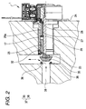
- a valve plug 35 is attached to the head piece 25 by press-fitting or by screwing, a valve seat 36 is provided in the fluid channel 38, and the valve plug 35 and the valve seat 16 in combination constitute a flow control valve 37.
- stator yokes 7 and 8 When current is applied to the coil 6 of each of the first and second stator units 3a and 3b, the stator yokes 7 and 8 are magnetized with N and S poles (or S and N poles), respectively, whereby the magnet 4 is rotated. Then, the screw portion 3a of the sleeve 3 fixed to the magnet 4 is rotated together, and the output shaft 2 which has the screw portion 2a engaging threadedly with the screw portion 3a is urged to rotate but is prevented from rotating due to the pin 29 set in the axially extending slits 26a of the spring holder 26 and therefore is caused to linearly move in the axial direction.
- the valve plug 35 disengages from the valve seat 36, thus the flow control valve 37 is opened allowing gas to flow through the fluid channel 38 as shown in Fig. 2 (the arrows indicate the direction of gas flow).
- the opening degree of the flow control valve 37 is controlled by the number of steps of the actuator 1.
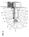
- Fig. 3 shows a safe condition, where the valve plug 35 makes tight contact with the valve seat 36 to keep the flow control valve 37 securely closed in order to stop gas flow when power supply is interrupted due to a power failure, or when current flow is interrupted by a wire broken due to a trouble in a control circuit (not shown).
- a second embodiment of the present invention will hereinafter be described with reference to Fig. 4.
- An actuator 50 according to the second embodiment of the present invention is structured to operate such that when a load exceeding a predetermined value is accidentally applied to a valve plug, a flow control valve is opened so as to prevent damages to the valve plug and the actuator.
- the actuator 50 shown in Fig. 4 is structured basically same as the actuator 1 according to the first embodiment shown in Fig. 1, and therefore in explaining the example of Fig. 4, any component parts corresponding to those in Fig 1 are denoted by the same reference numerals, and description will be focused on the difference from the actuator 1 shown in Fig. 1.
- the coil spring 27 as an extension spring is provided between the stopper plate 28 and the pin 29 so as to force the valve plug 35 to move to such a position as to make the flow control valve 37 closed, thus performing a fail-safe operation.
- a fail-safe operation is performed such that a coil spring 27 as an extension spring is provided between the solid portion of a spring holder 26 and a pin 29 so as to force a valve plug 35 to move to such a position as to make a flow control valve 37 open.
- the difference from the actuator 1 is also found in the configuration of the spring holder 26, and in the position of the coil spring 27.
- the spring holder 26 has shorter slits 26a in the actuator 50 than in the actuator 1, and the pin 29 is located closer to a sleeve 3 in the actuator 50 than in the actuator 1 thereby allowing the coil spring 27 to be provided between the solid portion of the spring holder 26 and the pin 29.
- a stator assembly 13 of the actuator 50 shown in Fig. 4 is fabricated in the same way as the stator assembly 13 of the actuator 1 shown in Fig. 1, and therefore an explanation thereof will be omitted.
- a rotor assembly 5 is fabricated as follows.
- a magnet 4 is fixedly attached onto the outer circumference of a sleeve 3, which is formed of, for example, PBT resin, and which is provided with a screw portion 3a constituted by a female screw.
- An output shaft 2 includes a screw portion 2a and a plain rod portion 2b.
- the screw portion 2a is constituted by a male screw, and a head piece 25 as a stopper is attached to an open end of the plain rod portion 2b.
- the head piece 25 has a screw hole 25a formed at its center, and the aforementioned valve plug 35 for flow control of fluid such as gas is fitted into the screw hole 25a.
- Bearings 18 and 33 are attached respectively to both axial ends of the sleeve 3, the sleeve 3 having also the magnet 4 attached thereto is put in a rotor case 20, a stopper plate 28 is placed on the bearing 18, and one end of a housing 17 having a flange portion 17a is inserted inside the rotor case 20 so that the housing 17 presses the stopper plate 28 for fixed attachment.
- the housing 17 is hollow-cylindrical and houses the spring holder 26 and the coil spring 27.
- the coil spring 27 is put in the spring holder 26, and the output shaft 2 with the pin 29 as a rotation stopper is inserted through the spring holder 26 and the coil spring 27.
- the pin 29 is put orthogonally through the plain rod portion 2b of the output shaft 2 so as to have its both ends sticking out from the outer circumference of the plain rod portion 2b.
- the screw portion 2a of the output shaft 2 is engaged threadedly with the screw portion 3a of the sleeve 3 such that the both ends of the pin 29 as a rotation stopper are set in respective slits 26a of the spring holder 26.
- two retainer pins 30 are put through respective holes formed at the housing 17 and through respective grooves formed at the solid portion of the spring holder 26 so that spring holder 26 is not allowed to move with respect to the housing 27.
- Respective two portions of the housing 17 and also the spring holder 26, through which the two retainer pins 30 are put, are positioned to oppose each other in the embodiment, but do not have to be so positioned, as long as the spring holder 26 is prevented from rotating with respect to the housing 17.
- the rotor case 20 is inserted between the magnet 4 and stator yokes 7 and 8, and therefore is preferably made of a non-magnetic material, for example, stainless steel, and preferably has a minimum possible thickness with a sufficient strength. Also, the rotor case 20 is preferably fabricated by method of drawing in view of cost.
- An O-ring 31 is made of an elastic material, such as rubber, is fitted in the groove formed on the outer circumference of the housing 17 so as to hermetically make contact with the rotor case 20, and serves to prevent the housing 17 from coming off the rotor case 20 as well as to seal up the gap between the housing 17 and the rotor case 20.
- the rotor case 20 with the rotor assembly 5 housed therein is press-fitted in the center opening of the stator assembly 13, and an additional front plate 24 having a center opening is placed on a front plate 23 so as to press the flange portion 17a of the housing 17.
- the additional front plate 24 is fixedly connected to the front plate 23 by mechanical means or by welding. If the front plate 23 is so structured as to press the flange portion 17a of the housing 17, then the additional front plate 24 can be eliminated. And, as mentioned earlier, the head piece 25 is attached to the open end of the plain rod portion 2b of the output shaft 2.
- the above-described actuator 50 shown in Fig. 4 is adapted to open the flow control valve 37 when a pressure exceeding a predetermined value is applied to the valve plug 35 in order to protect the valve plug 35 as well as the actuator 50 from being damaged.
- the housing 17 of the actuator 50 is put in a hole connecting to a fluid channel 38 such that an O-ring 32 provided at the end of the housing 17 seals up the gap between the housing 17 and the wall of the hole.
- the valve plug 35 is attached to the head piece 25 by press-fitting or by screwing, a valve seat 36 is provided in the fluid channel 38, and the valve plug 35 and the valve seat 16 in combination constitute the flow control valve 37.
- stator yokes 7 and 8 When current is applied to the coil 6, the stator yokes 7 and 8 are magnetized with N and S poles (or S and N poles), respectively, whereby the magnet 4 is rotated. Accordingly, the screw portion 3a of the sleeve 3 fixed to the magnet 4 is rotated together, and the output shaft 2 which has the screw portion 2a engaging threadedly with the screw portion 3a is urged to rotate but is prevented from rotating due to the pin 29 set in the axially extending slits 26a of the spring holder 26 and therefore is caused to linearly move in the axial direction.
- the output shaft 2 moves toward the valve seat 36 causing the pin 29 to compress the spring coil 27, and stops at a predetermined position for a predetermined opening degree of the flow control valve 37 (the arrows indicate the direction of gas flow).
- the opening degree of the flow control valve 37 is controlled by the number of steps of the actuator 1.
- Fig. 6 shows a damage-preventive state, in which the flow control valve 37 is opened (or opened wider) so as to relax gas pressure on the valve plug 35 when the pressure of gas flowing through the fluid channel 38 exceeds a prescribed value, whereby the valve plug 35 and the actuator 50 are prevented from being damaged.
- the gas pressure in the fluid channel 38 exceeds a prescribed value, the gas pressure is detected by a sensor (not shown), and an output signal is fed to a control circuit (not shown). Then, the control circuit outputs a control signal to interrupt power supply to the coils 6.
- the coil spring 27 When exciting current is interrupted to the coils 6, the coil spring 27 has its configuration restored causing the output shaft 2 to move toward the sleeve 3 forcing the sleeve 3 and the magnet 4 to rotate due to the screw portion 2a threadedly engaging with the screw portion 3a until the pin 29 hits the stopper plate 28. Consequently, the valve plug 35 is pulled away from the valve seat 36 so as to make the flow control valve 37 open wider, whereby the valve plug 35 and the actuator 50 are prevented from being damaged due to gas overpressure.
- the stopper plate 28 is not absolutely required if the pin 29 is otherwise stopped so as to be prohibited from coming into contact with the end of the sleeve 3 including the bearing 18.
- an extension coil spring is used for a fail-safe operation in case of emergency, but the present invention is not limited to use of an extension coil spring but may alternatively use a compression coil spring which is extended by application of an external force and is restored for contraction by release of the external force.
- both ends of the compression coil spring are engagingly attached to the stopper plate 28 and the pin 29, respectively
- both ends of the compression coil spring are engagingly attached to the solid portion of the spring holder 26 and the pin 29, respectively.
- the compressed height of the coil spring must be taken into consideration when setting the position of the pin 29.
- either an extension coil spring or a compression coil spring may be fastened with an accumulator latch, wherein when reduction in voltage or current of power supply is detected, the latch is electromagnetically released so as to force the output shaft into a safe condition.
Landscapes
- Engineering & Computer Science (AREA)
- General Engineering & Computer Science (AREA)
- Mechanical Engineering (AREA)
- Power Engineering (AREA)
- Electrically Driven Valve-Operating Means (AREA)
Abstract
Description
- The present invention relates to an actuator for a flow control valve to control flow in a fluid channel, and more particularly to an actuator integrally provided with a fail-safe function to mandatorily actuate a valve so as to provide a safe condition for a fluid channel when electric power supply is accidentally cut off for some reason.
- A flow control valve is conventionally used for gas flow control performed with a shutoff valve provided in a fluid channel of a gas supply equipment, and also for switching control of a refrigerant channel for air-conditioning. Such a flow control valve is driven by an actuator in which that the rotary motion of a motor shaft is converted into the linear motion of a valve by means of a pinion gear or a screw structure.
- Recently, a permanent magnet (PM) type stepping motor, which achieves a high positioning accuracy by means of step input, is increasingly combined with a mechanism to convert a rotary motion into a linear motion so that it can be used as an actuator.
- A flow control valve is used in, for example, a gas meter, which is equipped with a safety mechanism to prevent troubles. Such a safety mechanism has what is called a fail-safe function incorporated in a gas shutoff valve system, and operates such that a flow control valve is automatically shut so as to close a gas channel when power supply is stopped due to electric power failure or due to trouble of a control circuit.
- Fig. 7 is a schematic structural view of a conventional gas shutoff valve system provided with such a fail-safe function (refer to, for example, Japanese Patent Application Laid-Open No. 2003-042324).
- The gas shutoff valve system shown in Fig. 7 includes a
valve seat 101, avalve plug 102 adapted to block thevalve seat 101, avalve shaft 103 connected to thevalve plug 102, aguide 104 to cause thevalve shaft 103 to move linearly, aspring 105 to press thevalve plug 102 toward thevalve seat 101, astepping motor 106 as a rotarydevice having coils 111 and arotor 112 with anoutput shaft 107, afeed screw 108 as a feeding element formed on theoutput shaft 107, a movingblock 109 engaging threadedly with thefeed screw 108 so as to thrust thevalve plug 102, arotation stopper 110 to prohibit the movingblock 109 from rotating, and alid 113. When something abnormal occurs in gas supply, pulsing currents with respective phases different from each other are applied to thecoils 111 so as to rotate therotor 112, whereby the movingblock 109 moves toward thelid 113, and thevalve plug 102, urged by thespring 105, is caused to move together so as to block thevalve seat 101 thus stopping gas from flowing through. - Fig. 8 is a schematic structural view of another conventional gas shutoff valve system (refer to, for example, Japanese Patent Application Laid-Open No. 2003-222259).
- In the gas shutoff valve system shown in Fig. 8, when there is something abnormal detected in gas supply, pulsing currents with respective phases different from each other are applied to
respective wires 122 ofcoils 121 thereby rotating arotor 123, and then a movingblock 124, which engages threadedly with afeed screw 127 fixedly connected to therotor 123, and which has a groove engaging with arib 126 for prohibition of rotation, is caused to linearly move in the axial direction due to thefeed screw 127 rotating together with therotor 123. Avalve plug 128 is engagingly attached to the movingblock 124, and when the movingblock 124 moves toward avalve seat 130, asealing pad 129 of thevalve plug 128 is brought into contact with thevalve seat 130. And, when the movingblock 124 further moves toward thevalve seat 130, acoil spring 131 is further contracted so that aspring retaining portion 131 of the movingblock 124 is brought into contact with acylinder portion 133 of a sealingpad holding member 132, and thesealing pad 129 sags and is contracted, which causes the repulsion of the movingblock 124 to exceed the thrust of thefeed screw 127 consequently stopping the rotation of therotor 123. At this time, thevalve plug 128 is firmly pressed against thevalve seat 130 by force of thecoil spring 131, and gas flow is shut off. If electric power is turned off in this state, therotor 123 keeps its position due to holding torque, and thevalve plug 128 is kept pressed against thevalve seat 130 so as to keep the valve closed. - In the gas shutoff valve system shown in Fig. 7 as disclosed in the aforementioned Japanese Patent Application Laid-Open No. 2003-042324, the
spring 105 to press thevalve plug 102 against thevalve seat 101 is provided in agas channel 114, which makes the system complicated, and thespring 105 is difficult to replace, which results in deteriorated workability in maintenance. - In the gas shutoff valve system shown in Fig. 8 as disclosed in the aforementioned Japanese Patent Application Laid-Open No. 2003-222259, since the
coil spring 131 is attached at thevalve plug 128, thevalve plug 128 is prohibited from downsizing. Also, thecoil spring 131 must be prepared so as to fit to the configuration of eachvalve plug 128, which leads to an increased number of components. - The present invention has been made in light of the above problems, and it is an object of the present invention to provide an actuator which leverages a motor to actuate a flow control valve in a fluid channel, and which has built-in capability of performing a fail-safe operation, wherein maintenance work can be performed easily.
- In order to achieve the object, according to an aspect of the present invention, an actuator comprises: (a) a rotor assembly including *an output shaft having a screw portion constituted by a male screw formed on an outer circumference of the output shaft, having a plain rod portion toward the other end thereof, and having a pin attached to the plain rod portion so as to protrude therefrom toward an outside of the pin in a radial direction, *a sleeve having a screw portion constituted by a female screw formed on an inner circumference of the sleeve, the sleeve rotatably supported by bearings disposed respectively at both axial ends of the sleeve, wherein the screw portion of the sleeve is threadedly engaged with the screw portion of the output shaft so as to convert a rotary motion of the sleeve into a linear motion of the output shaft, and *a magnet fixedly disposed at an outer circumference of the sleeve; (b) a stator assembly functioning to rotate the magnet, and including **a coil, **a bobbin having the coil wound therearound, and **stator yokes coupled to each other so as to sandwich the bobbin; (c) a housing having a hollow-cylindrical configuration, and attached to the stator assembly; and (d) a fail-safe mechanism in the housing, the fail-safe mechanism comprising a coil spring disposed around the output shaft, and a spring holder disposed around the output shaft, and having slits to guide the pin attached to the output shaft into an axial direction movement. In the actuator described above, the coil spring and the spring holder constitute a fail-safe mechanism and are contained inside the housing. Consequently, a fail-safe mechanism is incorporated in the actuator as an integral unit, and therefore the mounting work and the maintenance work can be implemented easily.
- In the aspect of the present invention, the coil spring may be arranged at such a location that the output shaft is caused to move in a direction to achieve a fail-safe operation. Consequently, a versatile fail-safe operation is available according to the arrangement of the coil spring.
- In the aspect of the present invention, the coil spring may be an extension spring and located between the pin attached to the output shaft and the spring holder so that when electric power supply to the coil of the stator assembly is cut off, the output shaft is caused to move toward the stator assembly by force of the coil spring. This arrangement is suitable for a fail-safe operation achieved by opening a valve.
- In the aspect of the present invention, the actuator may further comprise a stopper plate disposed on one of the bearings located closer to the housing, and the coil spring may be an extension spring and located between the pin attached to the output shaft and the stopper plate so that when electric power supply to the coil of the stator assembly is cut off, the output shaft is caused to move away from the stator assembly by force of the coil spring. This structure is suitable for a fail-safe operation achieved by shutting valve.
- In the aspect of the present invention, the coil spring may be a compression spring and located between the pin attached to the output shaft and the spring holder so that when electric power supply to the coil of the stator assembly is cut off, the output shaft is caused to move away from the stator assembly by force of the coil spring. This arrangement is suitable for a fail-safe operation achieved by shutting a valve.
- In the aspect of the present invention, the actuator may further comprise a stopper plate disposed on one of the bearings located closer to the housing, and the coil spring may be a compression spring and located between the pin attached to the output shaft and the stopper plate so that when electric power supply to the coil of the stator assembly is cut off, the output shaft is caused to move toward the stator assembly by force of the coil spring. This arrangement is suitable for a fail-safe operation achieved by opening a valve.
- In the aspect of the present invention, the housing may include a flange portion at one end portion thereof, and may be fixedly attached to the stator assembly by means of a front plate pressing on the flange portion. Thus, the housing is securely attached to the stator assembly.
- In the aspect of the present invention, the actuator may further comprise a rotor case having a cup-like configuration, the rotor case being disposed between the rotor assembly and the stator assembly so as to constitute a hermetic partition therebetween. Consequently, a gap between the rotor assembly and the stator assembly is completely sealed up to ensure a safe condition.
- In the aspect of the present invention, the actuator may further comprise a sealing member disposed around the housing. This structure seals up a gap between the housing and the equipment applied, thus a safe condition is ensured.
-
- Fig. 1 is a side view (partly cross sectioned) of an actuator according to a first embodiment of the present invention;
- Fig. 2 is a cross sectional view of a fluid channel in which the actuator of Fig. 1 is mounted;
- Fig. 3 is an explanatory view of the fluid channel of Fig. 2 for explanation of a fail-safe operation, wherein a flow control valve is closed;
- Fig. 4 is a side view (partly cross sectioned) of an actuator according to a second embodiment of the present invention;
- Fig. 5 is a cross sectional view of a fluid channel in which the actuator of Fig. 4 is mounted;
- Fig. 6 is an explanatory view of the fluid channel of Fig. 5 for explanation of a fail-safe operation, wherein a flow control valve is open;
- Fig. 7 is a schematic structural view of a conventional gas shutoff valve system; and
- Fig. 8 is a schematic structural view of another conventional gas shutoff valve system.
- Preferred embodiments of the present invention will hereinafter be described with reference to the accompanying drawings.
- Referring to Fig. 1, an actuator 1 according to a first embodiment of the present invention generally comprises a
rotor assembly 5, astator assembly 13, and ahousing 17. - The
rotor assembly 5 includes anoutput shaft 2, asleeve 3, and amagnet 4 with multi-polar magnetization. Theoutput shaft 2 has ascrew portion 2a and aplain rod portion 2b, thesleeve 3 is formed of synthetic resin and has ascrew portion 3a located at an elevated portion on its inner circumferential surface, and themagnet 4 is shaped hollow-cylindrical and fixedly disposed at the outer circumference of thesleeve 3. Thescrew portion 2a is located at a portion of the outer circumferential surface of theoutput shaft 2 and engages threadedly with thescrew portion 3a of thesleeve 3. Ahead piece 25 is attached to an open end of theplain rod portion 2b of theoutput shaft 2, and a valve plug (not shown in Fig. 1) is attached to thehead piece 25 so as to oppose a valve seat (not shown in Fig. 1) disposed in a fluid channel (not shown in Fig. 1) thereby functioning to open and close the fluid channel. - The
stator assembly 13 is disposed outside themagnet 4 of therotor assembly 5 and includes first andsecond stator units stator yokes bobbin 9 having acoil 6 wound therearound. Thestator assembly 13 further includes awiring board unit 14 and afront plate 23 which is placed on thefirst stator unit 13a coaxially stacked on thesecond stator unit 13b. Thestator yokes magnet 4 of therotor assembly 5. Thebobbin 9 has a substantially squared C-shaped cross section and is provided integrally with aterminal block 10, andterminal pins 11 are implanted in theterminal block 10. Acover 12 is attached so as to enclose thecoil 6 thereby preventing dusts from coming in to sit on thecoil 6. Thefront plate 23 is for attachment of the actuator 1 to an outside apparatus. The constituent components described above are resin injection molded for solid structure. Thewiring board unit 14 includes a printedboard 14a and apin retainer 14b. Thepin retainer 14b is disposed outside the terminal blocks 10 and holds the printedboard 14a.Wire cables 16 connected to the printedboard 14a lead out through thepin retainer 14b. - The
housing 17 is shaped in a hollow-cylinder, disposed around theplain rod portion 2b of theoutput shaft 2, and has aflange portion 17a toward one end thereof. Aspring holder 26 shaped in a cylinder with solid and hollow portions, and havingslits 26a extending in the axial direction, acoil spring 27 working as an extension spring adapted to return to an initial condition after contraction, astopper plate 28, apin 29, and tworetainer pins 30 are fitted in thehousing 17, and O-rings housing 17. Thepin 29 is inserted orthogonally through theplain rod portion 2b of theoutput shaft 2 and has its both ends sticking out. Thecoil spring 27 is disposed between thepin 29 and thestopper plate 28 and in contact with both thereof so as to exert its action on both thereof. - The actuator 1 further comprises a
rotor case 20 shaped like a cup and disposed between the rotor assembly and the stator assembly, abearing 18 and asleeve bearing 33 to support respective ends of thesleeve 3, andcollar members - The
stator assembly 13 is manufactured as follows. - The stator yokes 7 and 8, which are made of a soft-magnetic material, such as a galvanized steel plate (SECC), an electromagnetic soft steel (SUY), and a silicon steel plate, and which each have a plurality of pole teeth arrayed in a comb-like arrangement, are coupled to each other so as to sandwich the
bobbin 9 having thecoil 6 wound therearound, such that respective pole tooth arrays intermesh with each other with a gap formed therebetween at a phase difference of 180 degrees in terms of electrical angle. Thus, thefirst stator unit 3a is completed. The second stator unit 3b is fabricated in the same way. - The
first stator unit 3a is stacked on the second stator unit 3b in a mold (not shown) such that thefirst stator unit 3a is shifted from the second stator unit 3b by an electrical angle of 90 degrees. Synthetic resin, for example, polybutylene terephthalate (PBT), is injected in the mold. The synthetic resin injected fills up the gap between the respective pole tooth arrays of the stator yokes 7 and 8 on each of the first andsecond stator units 3a and 3b, and at the same time formslower bosses 21 andupper bosses 22. Thus, the first andsecond stator units 3a and 3b are rigidly coupled to each other by resin. - The
front plate 23 having an opening at its center is put on and welded to thefirst stator unit 3a such that holes formed in thefront plate 23 are engaged with the aforementionedupper bosses 22. Then, thewiring board unit 14, which includes the printedboard 14a and thepin retainer 14b formed of synthetic resin, is attached to the outer circumference of the first andsecond stator units 3a and 3b coupled together. Thus, thestator assembly 13 is completed. - The
rotor assembly 5 is manufactured as follows. - The
magnet 4 is fixed onto the outer circumference of thesleeve 3 which is provided with thescrew portion 3a constituted by a female screw, thebearings sleeve 3, and thesleeve 3 thus furnished is put in therotor case 20. Therotor case 20 is shaped into a cup-like configuration and has an inner diameter slightly larger than an outer diameter of themagnet 4 so as to allow themagnet 4 to rotate. - The
stopper plate 28 is placed on thebearing 18, and the one end of thehousing 17 having theflange portion 17a is inserted between the bearing 18 and therotor case 20 so that thehousing 17 presses thestopper plate 28 for fixed attachment. As described above, thehousing 17 is hollow-cylindrical and houses thespring holder 26 and thecoil spring 27. - The
output shaft 2 having thepin 29 as a rotation stopper inserted orthogonally therethough is put through thecoil spring 27, and thescrew portion 2a of theoutput shaft 2 is brought into engagement with thescrew portion 3a of thesleeve 3. Theoutput shaft 2 has thescrew portion 2a and theplain rod portion 2b which are continuous with each other. At a later process, thehead piece 25 as a stopper member is to be attached to the open end of the output shaft positioned toward theplain rod portion 2b. Ascrew hole 25a is formed at the center of thehead piece 25, and a valve plug for controlling flow of fluid such as gas is fitted into thescrew hole 25a. Thepin 29 serves also as a stopper for thecoil sprint 27. - The
spring holder 26 is attached around theplain rod portion 2b such that the both ends of thepin 29 sticking out from theplain rod portion 2b are put through theslits 26a of thespring holder 26, and then the tworetainer pins 30 are put through respective holes formed at the other end of thehousing 17 opposite to the one end having theflange portion 17a and through respective grooves formed at one end of thespring holder 26 so thatspring holder 26 is not allowed to move with respect to thehousing 27. Thus, therotor assembly 5 is completed. - Respective two portions of the
housing 17 and also thespring holder 26, through which the tworetainer pins 30 are put, are positioned to oppose each other in the embodiment, but do not have to be so positioned, as long as thespring holder 26 is prevented from rotating with respect to thehousing 17. - The
rotor case 20 is inserted between themagnet 4 and the stator yokes 7 and 8, and therefore is preferably made of a non-magnetic material, for example, stainless steel, and preferably has a minimum possible thickness with a sufficient strength. Also, therotor case 20 is preferably fabricated by method of drawing in view of cost. The O-ring 31 is made of an elastic material, such as rubber, is fitted in the groove formed on the outer circumference of thehousing 17 so as to hermetically make contact with therotor case 20, and serves to prevent thehousing 17 from coming off therotor case 20 as well as to seal up the gap between thehousing 17 and therotor case 20. - The
rotor case 20 having therotor assembly 5 housed therein is press-fitted in the center opening of thestator assembly 13, and an additionalfront plate 24 having a center opening is placed on thefront plate 23 so as to press theflange portion 17a of thehousing 17. The additionalfront plate 24 may be fixedly connected to thefront plate 23 by mechanical means or by welding. If thefront plate 23 is so structured as to press theflange portion 17a of thehousing 17, then the additionalfront plate 24 can be eliminated. And, as mentioned earlier, thehead piece 25 is attached to the open end of theoutput shaft 2, thus completing the actuator 1. - The actuator 1 shown in Fig. 1 has a fail-safe function such that when something abnormal occurs in the actuator 1, for example, power supply is stopped, or a wire for a coil is broken thus interrupting current, a flow control valve is either automatically driven for a safe condition, or automatically closed to shut off gas flow.
- Referring to Fig. 2, the
housing 17 of the actuator 1 is put in a hole connecting to afluid channel 38 such that the step portion of the additionalfront plate 24 is fitted loosely in a circular recess having a larger diameter than the aforementioned hole. The O-ring 32 provided at the end of thehousing 17 seals up the gap between thehousing 17 and the wall of the hole. Avalve plug 35 is attached to thehead piece 25 by press-fitting or by screwing, avalve seat 36 is provided in thefluid channel 38, and thevalve plug 35 and thevalve seat 16 in combination constitute aflow control valve 37. - When current is applied to the
coil 6 of each of the first andsecond stator units 3a and 3b, the stator yokes 7 and 8 are magnetized with N and S poles (or S and N poles), respectively, whereby themagnet 4 is rotated. Then, thescrew portion 3a of thesleeve 3 fixed to themagnet 4 is rotated together, and theoutput shaft 2 which has thescrew portion 2a engaging threadedly with thescrew portion 3a is urged to rotate but is prevented from rotating due to thepin 29 set in theaxially extending slits 26a of thespring holder 26 and therefore is caused to linearly move in the axial direction. When theoutput shaft 2 moves toward therotor sleeve 3 causing thepin 29 to compress thespring coil 27, thevalve plug 35 disengages from thevalve seat 36, thus theflow control valve 37 is opened allowing gas to flow through thefluid channel 38 as shown in Fig. 2 (the arrows indicate the direction of gas flow). The opening degree of theflow control valve 37 is controlled by the number of steps of the actuator 1. - Fig. 3 shows a safe condition, where the
valve plug 35 makes tight contact with thevalve seat 36 to keep theflow control valve 37 securely closed in order to stop gas flow when power supply is interrupted due to a power failure, or when current flow is interrupted by a wire broken due to a trouble in a control circuit (not shown). - When current flow to the
coil 6 is accidentally interrupted, thepin 29 is pressed toward thevalve plug 37 by a restoring force of thecoil spring 27 with respect to thestopper plate 28 as a reference position, and theoutput shaft 2 having thepin 29 fixed thereto moves toward thevalve seat 36 forcing thesleeve 3 and themagnet 4 to rotate due to thescrew portion 2a threadedly engaging with thescrew portion 3a until thepin 29 hits the solid portion of thespring holder 26. Thus, thevalve plug 35 is brought into hermetic contact with thevalve seat 36 by means of thecoil spring 27 so as to make theflow control valve 37 closed thereby shutting off gas flow as shown in Fig. 3. - A second embodiment of the present invention will hereinafter be described with reference to Fig. 4. An
actuator 50 according to the second embodiment of the present invention is structured to operate such that when a load exceeding a predetermined value is accidentally applied to a valve plug, a flow control valve is opened so as to prevent damages to the valve plug and the actuator. Theactuator 50 shown in Fig. 4 is structured basically same as the actuator 1 according to the first embodiment shown in Fig. 1, and therefore in explaining the example of Fig. 4, any component parts corresponding to those in Fig 1 are denoted by the same reference numerals, and description will be focused on the difference from the actuator 1 shown in Fig. 1. - In the actuator 1 according to the first embodiment shown in Fig. 1, the
coil spring 27 as an extension spring is provided between thestopper plate 28 and thepin 29 so as to force thevalve plug 35 to move to such a position as to make theflow control valve 37 closed, thus performing a fail-safe operation. On the other hand, in theactuator 50 according to the second embodiment shown in Fig. 4, a fail-safe operation is performed such that acoil spring 27 as an extension spring is provided between the solid portion of aspring holder 26 and apin 29 so as to force avalve plug 35 to move to such a position as to make aflow control valve 37 open. - The difference from the actuator 1 is also found in the configuration of the
spring holder 26, and in the position of thecoil spring 27. Specifically, thespring holder 26 hasshorter slits 26a in theactuator 50 than in the actuator 1, and thepin 29 is located closer to asleeve 3 in theactuator 50 than in the actuator 1 thereby allowing thecoil spring 27 to be provided between the solid portion of thespring holder 26 and thepin 29. - A
stator assembly 13 of theactuator 50 shown in Fig. 4 is fabricated in the same way as thestator assembly 13 of the actuator 1 shown in Fig. 1, and therefore an explanation thereof will be omitted. - A
rotor assembly 5 is fabricated as follows. - A
magnet 4 is fixedly attached onto the outer circumference of asleeve 3, which is formed of, for example, PBT resin, and which is provided with ascrew portion 3a constituted by a female screw. - An
output shaft 2 includes ascrew portion 2a and aplain rod portion 2b. Thescrew portion 2a is constituted by a male screw, and ahead piece 25 as a stopper is attached to an open end of theplain rod portion 2b. Thehead piece 25 has ascrew hole 25a formed at its center, and theaforementioned valve plug 35 for flow control of fluid such as gas is fitted into thescrew hole 25a. -
Bearings sleeve 3, thesleeve 3 having also themagnet 4 attached thereto is put in arotor case 20, astopper plate 28 is placed on thebearing 18, and one end of ahousing 17 having aflange portion 17a is inserted inside therotor case 20 so that thehousing 17 presses thestopper plate 28 for fixed attachment. Thehousing 17 is hollow-cylindrical and houses thespring holder 26 and thecoil spring 27. - The
coil spring 27 is put in thespring holder 26, and theoutput shaft 2 with thepin 29 as a rotation stopper is inserted through thespring holder 26 and thecoil spring 27. Thepin 29 is put orthogonally through theplain rod portion 2b of theoutput shaft 2 so as to have its both ends sticking out from the outer circumference of theplain rod portion 2b. - The
screw portion 2a of theoutput shaft 2 is engaged threadedly with thescrew portion 3a of thesleeve 3 such that the both ends of thepin 29 as a rotation stopper are set inrespective slits 26a of thespring holder 26. Then, tworetainer pins 30 are put through respective holes formed at thehousing 17 and through respective grooves formed at the solid portion of thespring holder 26 so thatspring holder 26 is not allowed to move with respect to thehousing 27. Thus, therotor assembly 5 is completed. - Respective two portions of the
housing 17 and also thespring holder 26, through which the tworetainer pins 30 are put, are positioned to oppose each other in the embodiment, but do not have to be so positioned, as long as thespring holder 26 is prevented from rotating with respect to thehousing 17. - The
rotor case 20 is inserted between themagnet 4 andstator yokes rotor case 20 is preferably fabricated by method of drawing in view of cost. An O-ring 31 is made of an elastic material, such as rubber, is fitted in the groove formed on the outer circumference of thehousing 17 so as to hermetically make contact with therotor case 20, and serves to prevent thehousing 17 from coming off therotor case 20 as well as to seal up the gap between thehousing 17 and therotor case 20. - The
rotor case 20 with therotor assembly 5 housed therein is press-fitted in the center opening of thestator assembly 13, and an additionalfront plate 24 having a center opening is placed on afront plate 23 so as to press theflange portion 17a of thehousing 17. The additionalfront plate 24 is fixedly connected to thefront plate 23 by mechanical means or by welding. If thefront plate 23 is so structured as to press theflange portion 17a of thehousing 17, then the additionalfront plate 24 can be eliminated. And, as mentioned earlier, thehead piece 25 is attached to the open end of theplain rod portion 2b of theoutput shaft 2. In this connection, depending on the length of theoutput shaft 2, current is applied tocoils 6 so as to move theoutput shaft 2 in the direction to compress thecoil spring 27 thereby making the open end of theplain rod portion 2b stick out from the end face of thehousing 17. Thus, theactuator 50 is completed. - The above-described
actuator 50 shown in Fig. 4 is adapted to open theflow control valve 37 when a pressure exceeding a predetermined value is applied to thevalve plug 35 in order to protect thevalve plug 35 as well as the actuator 50 from being damaged. - Referring to Fig. 5, the
housing 17 of theactuator 50 is put in a hole connecting to afluid channel 38 such that an O-ring 32 provided at the end of thehousing 17 seals up the gap between thehousing 17 and the wall of the hole. Thevalve plug 35 is attached to thehead piece 25 by press-fitting or by screwing, avalve seat 36 is provided in thefluid channel 38, and thevalve plug 35 and thevalve seat 16 in combination constitute theflow control valve 37. - When current is applied to the
coil 6, the stator yokes 7 and 8 are magnetized with N and S poles (or S and N poles), respectively, whereby themagnet 4 is rotated. Accordingly, thescrew portion 3a of thesleeve 3 fixed to themagnet 4 is rotated together, and theoutput shaft 2 which has thescrew portion 2a engaging threadedly with thescrew portion 3a is urged to rotate but is prevented from rotating due to thepin 29 set in theaxially extending slits 26a of thespring holder 26 and therefore is caused to linearly move in the axial direction. Theoutput shaft 2 moves toward thevalve seat 36 causing thepin 29 to compress thespring coil 27, and stops at a predetermined position for a predetermined opening degree of the flow control valve 37 (the arrows indicate the direction of gas flow). The opening degree of theflow control valve 37 is controlled by the number of steps of the actuator 1. - Fig. 6 shows a damage-preventive state, in which the
flow control valve 37 is opened (or opened wider) so as to relax gas pressure on thevalve plug 35 when the pressure of gas flowing through thefluid channel 38 exceeds a prescribed value, whereby thevalve plug 35 and theactuator 50 are prevented from being damaged. - When the gas pressure in the
fluid channel 38 exceeds a prescribed value, the gas pressure is detected by a sensor (not shown), and an output signal is fed to a control circuit (not shown). Then, the control circuit outputs a control signal to interrupt power supply to thecoils 6. When exciting current is interrupted to thecoils 6, thecoil spring 27 has its configuration restored causing theoutput shaft 2 to move toward thesleeve 3 forcing thesleeve 3 and themagnet 4 to rotate due to thescrew portion 2a threadedly engaging with thescrew portion 3a until thepin 29 hits thestopper plate 28. Consequently, thevalve plug 35 is pulled away from thevalve seat 36 so as to make theflow control valve 37 open wider, whereby thevalve plug 35 and theactuator 50 are prevented from being damaged due to gas overpressure. - In the second embodiment described above, the
stopper plate 28 is not absolutely required if thepin 29 is otherwise stopped so as to be prohibited from coming into contact with the end of thesleeve 3 including thebearing 18. - In the embodiments described above, an extension coil spring is used for a fail-safe operation in case of emergency, but the present invention is not limited to use of an extension coil spring but may alternatively use a compression coil spring which is extended by application of an external force and is restored for contraction by release of the external force.
- When a compression coil spring is used, components must be attached to the compression coil spring in such a manner as to allow its spring force to duly act on the components. Specifically, for example in case of the first embodiment shown in Fig. 1, both ends of the compression coil spring are engagingly attached to the
stopper plate 28 and thepin 29, respectively, and in case of the second embodiment shown in Fig. 4, both ends of the compression coil spring are engagingly attached to the solid portion of thespring holder 26 and thepin 29, respectively. Also, the compressed height of the coil spring must be taken into consideration when setting the position of thepin 29. - Alternatively, either an extension coil spring or a compression coil spring may be fastened with an accumulator latch, wherein when reduction in voltage or current of power supply is detected, the latch is electromagnetically released so as to force the output shaft into a safe condition.
- Obviously, many modifications and variations of the present invention are possible in light of the above teachings. Thus, it is to be understood that, within the scope of the appended claims, the invention may be practiced otherwise than as specifically described above.
- This application is based on Japanese Patent application JP 2004-208122, filed July 15, 2004, the entire content of which is hereby incorporated by reference. This claim for priority benefit is being filed concurrently with the filing of this application.
- It is explicitly stated that all features disclosed in the description and/or the claims are intended to be disclosed separately and independently from each other for the purpose of original disclosure as well as for the purpose of restricting the claimed invention independent of the composition of the features in the embodiments and/or the claims. It is explicitly stated that all value ranges or indications of groups of entities disclose every possible intermediate value or intermediate entity for the purpose of original disclosure as well as for the purpose of restricting the claimed invention, in particular as limits of value ranges.
Claims (9)
- An actuator comprising:(a) a rotor assembly (5) comprising
an output shaft (2) having a first screw portion (2a) with a male screw on an outer circumference of the output shaft (2), having a plain rod portion (2b), and having a pin (29) attached to the plain rod portion (2b) so as to protrude therefrom toward an outside of the pin (29) in a radial direction;
a sleeve (3) having a second screw portion (3a) with a female screw on an inner circumference of the sleeve (3), the sleeve (3) rotatably supported by bearings (18 and 33) disposed respectively at both axial ends of the sleeve (3), wherein the first screw portion (2a) is threadedly engaged with the second screw portion (3a) so as to convert a rotary motion of the sleeve (3) into a linear motion of the output shaft (2), and
a magnet (4) fixedly disposed at an outer circumference of the sleeve (3);(b) a stator assembly (13) that rotates the magnet (4), and comprises
a coil (6),
a bobbin (9) having the coil (6) wound therearound, and
stator yokes (7 and 8) coupled to each other so as to sandwich the bobbin (9);(c) a housing (17) having a hollow-cylindrical configuration, and attached to the stator assembly (13);
characterized in that
the actuator further comprises (d) a fail-safe mechanism integrally built in the housing, the fail-safe mechanism comprising:a coil spring (27) disposed around the output shaft (2); and
a spring holder (26) disposed around the output shaft (2), and having slits (26a) to guide the pin (29) attached to the output shaft (2) into an axial direction. - An actuator according to Claim 1, wherein the coil spring (27) is disposed at such a location that the output shaft (2) is caused to move in a direction to achieve a fail-safe operation.
- An actuator according to Claim 2, wherein the coil spring (27) is an extension spring and located between the pin (29) attached to the output shaft (2) and the spring holder (26) so that when electric power supply to the coil (6) of the stator assembly (13) is cut off, the output shaft (2) is caused to move toward the stator assembly (13) by force of the coil spring (27).
- An actuator according to Claim 2, wherein the actuator further comprises a stopper plate (28) disposed on one (18) of the bearings (18 and 33) located closer to the housing (17), and wherein the coil spring (27) is an compression spring and located between the pin (29) attached to the output shaft (2) and the stopper plate (28) so that when electric power supply to the coil (6) of the stator assembly (13) is cut off, the output shaft (2) is caused to move away from the stator assembly (13) by force of the coil spring (27).
- An actuator according to Claim 2, wherein the coil spring (27) is a compression spring and located between the pin (29) attached to the output shaft (2) and the spring holder (26) so that when electric power supply to the coil (6) of the stator assembly (13) is cut off, the output shaft (2) is caused to move away from the stator assembly (13) by force of the coil spring (27).
- An actuator according to Claim 2, wherein the actuator further comprises a stopper plate (28) disposed on one (18) of the bearings (18 and 33) located closer to the housing (17), and wherein the coil spring (27) is a compression spring and located between the pin (29) attached to the output shaft (2) and the stopper plate (28) so that when electric power supply to the coil (6) of the stator assembly (13) is cut off, the output shaft (2) is caused to move toward the stator assembly (13) by force of the coil spring (27).
- An actuator according to any one of Claims 1 to 6, wherein the housing (17) includes a flange portion (17a) at one end portion thereof, and is fixedly attached to the stator assembly (13) by means of a front plate (23 or 24) pressing on the flange portion (17).
- An actuator according to any one of Claims 1 to 7, wherein the actuator further comprises a rotor case (20) having a cup-like configuration, and the rotor case (20) is disposed between the rotor assembly (5) and the stator assembly (13) so as to constitute a hermetic partition therebetween.
- An actuator according to any one of Claims 1 to 8, wherein the actuator further comprises a ring-like sealing member (32) around the housing (17).
Applications Claiming Priority (1)
| Application Number | Priority Date | Filing Date | Title |
|---|---|---|---|
| JP2004208122A JP4565913B2 (en) | 2004-07-15 | 2004-07-15 | Actuator |
Publications (2)
| Publication Number | Publication Date |
|---|---|
| EP1617115A1 true EP1617115A1 (en) | 2006-01-18 |
| EP1617115B1 EP1617115B1 (en) | 2008-06-18 |
Family
ID=34982369
Family Applications (1)
| Application Number | Title | Priority Date | Filing Date |
|---|---|---|---|
| EP05015022A Expired - Lifetime EP1617115B1 (en) | 2004-07-15 | 2005-07-11 | Actuator integrally provided with fail-safe function |
Country Status (4)
| Country | Link |
|---|---|
| US (1) | US7210665B2 (en) |
| EP (1) | EP1617115B1 (en) |
| JP (1) | JP4565913B2 (en) |
| DE (1) | DE602005007537D1 (en) |
Cited By (3)
| Publication number | Priority date | Publication date | Assignee | Title |
|---|---|---|---|---|
| CN102829232A (en) * | 2011-06-14 | 2012-12-19 | Tlx技术有限公司 | Solenoid interlock for booster actuator |
| DE102013109997A1 (en) | 2013-09-11 | 2015-03-12 | Minebea Co., Ltd. | actuator |
| WO2015091737A1 (en) * | 2013-12-19 | 2015-06-25 | Robert Bosch Gmbh | Valve |
Families Citing this family (10)
| Publication number | Priority date | Publication date | Assignee | Title |
|---|---|---|---|---|
| US7708254B2 (en) | 2007-08-07 | 2010-05-04 | Warren Controls, Inc. | Actuator apparatus for operating and locking a control valve and a method for its use |
| US8104313B2 (en) | 2007-11-27 | 2012-01-31 | Wolfe's Den, Llc | Security enclosure for a gun |
| KR101558563B1 (en) * | 2008-07-28 | 2015-10-08 | 엘지이노텍 주식회사 | Step Actuator |
| KR101134603B1 (en) * | 2008-10-06 | 2012-04-09 | 엘지이노텍 주식회사 | Stepping motor |
| JP5600760B2 (en) * | 2013-02-05 | 2014-10-01 | 島津エミット株式会社 | Electric valve actuator |
| US9958083B1 (en) * | 2016-10-27 | 2018-05-01 | National Enviornmental Products, Ltd. | Force limited valve actuator and method therefor |
| JP2018078698A (en) * | 2016-11-08 | 2018-05-17 | Ntn株式会社 | Direct acting type electric actuator |
| CN211820848U (en) * | 2019-12-03 | 2020-10-30 | 合肥威尔燃油系统股份有限公司北京分公司 | Fuel cell air inlet control valve |
| CN112671157A (en) * | 2020-12-04 | 2021-04-16 | 北京自动化控制设备研究所 | Integrated linear actuator driven by composite material |
| DE102022204163A1 (en) * | 2022-04-28 | 2023-11-02 | Robert Bosch Gesellschaft mit beschränkter Haftung | Valve device with a rotary drive and fluid system |
Citations (5)
| Publication number | Priority date | Publication date | Assignee | Title |
|---|---|---|---|---|
| JPH01316581A (en) * | 1988-06-14 | 1989-12-21 | Mitsubishi Electric Corp | Flow control valve |
| US5060910A (en) * | 1990-03-15 | 1991-10-29 | Aisan Kogyo Kabushiki Kaisha | Flow control device |
| DE4423313A1 (en) * | 1994-07-02 | 1996-01-04 | Pierburg Gmbh | Electrically-driven setting element with self-locking function |
| JP2003227575A (en) * | 2002-02-01 | 2003-08-15 | Saginomiya Seisakusho Inc | Electric flow control valve |
| WO2004038269A1 (en) * | 2002-10-28 | 2004-05-06 | Societe Industrielle De Sonceboz S.A. | Linear valve actuator |
Family Cites Families (10)
| Publication number | Priority date | Publication date | Assignee | Title |
|---|---|---|---|---|
| US4480614A (en) * | 1980-10-06 | 1984-11-06 | Toyota Jidosha K.K. | Idling speed control device of an internal combustion engine |
| US4393319A (en) * | 1980-12-08 | 1983-07-12 | General Motors Corporation | Electric motor powered actuator |
| US4501981A (en) * | 1981-10-15 | 1985-02-26 | Haydon Switch & Instrument, Inc. | Return-to-zero stepper motor |
| JPH087807Y2 (en) * | 1991-03-26 | 1996-03-04 | アスモ株式会社 | Electric motor |
| GB9415648D0 (en) * | 1994-08-03 | 1994-09-21 | Rotork Controls | Differential drive linear actuator |
| DE4446605A1 (en) * | 1994-12-24 | 1996-06-27 | Abb Patent Gmbh | Valve for steam turbine |
| US5983743A (en) * | 1997-04-03 | 1999-11-16 | Dresser Industries, Inc. | Actuator assembly |
| WO1999043072A1 (en) * | 1998-02-23 | 1999-08-26 | Mitsubishi Denki Kabushiki Kaisha | Control valve apparatus |
| JP4821063B2 (en) | 2001-07-27 | 2011-11-24 | パナソニック株式会社 | Shut-off valve |
| JP2003222259A (en) | 2002-01-28 | 2003-08-08 | Matsushita Electric Ind Co Ltd | Shut-off valve |
-
2004
- 2004-07-15 JP JP2004208122A patent/JP4565913B2/en not_active Expired - Fee Related
-
2005
- 2005-07-11 EP EP05015022A patent/EP1617115B1/en not_active Expired - Lifetime
- 2005-07-11 DE DE602005007537T patent/DE602005007537D1/en not_active Expired - Fee Related
- 2005-07-14 US US11/180,598 patent/US7210665B2/en not_active Expired - Lifetime
Patent Citations (5)
| Publication number | Priority date | Publication date | Assignee | Title |
|---|---|---|---|---|
| JPH01316581A (en) * | 1988-06-14 | 1989-12-21 | Mitsubishi Electric Corp | Flow control valve |
| US5060910A (en) * | 1990-03-15 | 1991-10-29 | Aisan Kogyo Kabushiki Kaisha | Flow control device |
| DE4423313A1 (en) * | 1994-07-02 | 1996-01-04 | Pierburg Gmbh | Electrically-driven setting element with self-locking function |
| JP2003227575A (en) * | 2002-02-01 | 2003-08-15 | Saginomiya Seisakusho Inc | Electric flow control valve |
| WO2004038269A1 (en) * | 2002-10-28 | 2004-05-06 | Societe Industrielle De Sonceboz S.A. | Linear valve actuator |
Non-Patent Citations (2)
| Title |
|---|
| PATENT ABSTRACTS OF JAPAN vol. 014, no. 119 (M - 0945) 6 March 1990 (1990-03-06) * |
| PATENT ABSTRACTS OF JAPAN vol. 2003, no. 12 5 December 2003 (2003-12-05) * |
Cited By (4)
| Publication number | Priority date | Publication date | Assignee | Title |
|---|---|---|---|---|
| CN102829232A (en) * | 2011-06-14 | 2012-12-19 | Tlx技术有限公司 | Solenoid interlock for booster actuator |
| CN102829232B (en) * | 2011-06-14 | 2016-02-24 | Tlx技术有限公司 | For the solenoid interlock of booster actuator |
| DE102013109997A1 (en) | 2013-09-11 | 2015-03-12 | Minebea Co., Ltd. | actuator |
| WO2015091737A1 (en) * | 2013-12-19 | 2015-06-25 | Robert Bosch Gmbh | Valve |
Also Published As
| Publication number | Publication date |
|---|---|
| JP2006029426A (en) | 2006-02-02 |
| JP4565913B2 (en) | 2010-10-20 |
| US7210665B2 (en) | 2007-05-01 |
| DE602005007537D1 (en) | 2008-07-31 |
| EP1617115B1 (en) | 2008-06-18 |
| US20060011879A1 (en) | 2006-01-19 |
Similar Documents
| Publication | Publication Date | Title |
|---|---|---|
| US7210665B2 (en) | Actuator integrally provided with fail-safe function | |
| EP1513242B1 (en) | Claw-pole type stepping motor | |
| JP4457038B2 (en) | Motor driven throttle control device for internal combustion engine | |
| US7375446B2 (en) | Actuator including rotor case and housing with sealing unit for hermetic structure | |
| US6753629B2 (en) | Brushless DC motor | |
| JP3911671B2 (en) | motor | |
| EP1729400B1 (en) | Motor | |
| JP4531359B2 (en) | motor | |
| EP2267735B1 (en) | Electromagnetic coil device | |
| US20090294713A1 (en) | Flow rate control valve | |
| EP3259510B1 (en) | Solenoid apparatus | |
| US6541958B2 (en) | Rotation detecting device | |
| CN112421857B (en) | Motor | |
| US20150333597A1 (en) | Valve provided with a multiphase linear actuator for high pressure dosing | |
| CN100386548C (en) | break valve | |
| CN102213175B (en) | Sealing device and starting device for pre-engagement actuator | |
| JP4699499B2 (en) | motor | |
| JP2001187978A (en) | Shut-off valve | |
| JPH1089520A (en) | Actuator | |
| JP4932803B2 (en) | motor | |
| KR20260002992A (en) | Electric valves and valve devices | |
| JP2007116797A (en) | Motor and valve device using the same | |
| JPH0450566A (en) | Control valve device | |
| JPH0488276A (en) | Control valve device for engine | |
| JP2005151657A (en) | Stepping motor |
Legal Events
| Date | Code | Title | Description |
|---|---|---|---|
| PUAI | Public reference made under article 153(3) epc to a published international application that has entered the european phase |
Free format text: ORIGINAL CODE: 0009012 |
|
| AK | Designated contracting states |
Kind code of ref document: A1 Designated state(s): AT BE BG CH CY CZ DE DK EE ES FI FR GB GR HU IE IS IT LI LT LU LV MC NL PL PT RO SE SI SK TR |
|
| AX | Request for extension of the european patent |
Extension state: AL BA HR MK YU |
|
| 17P | Request for examination filed |
Effective date: 20060710 |
|
| AKX | Designation fees paid |
Designated state(s): DE FR IT |
|
| GRAP | Despatch of communication of intention to grant a patent |
Free format text: ORIGINAL CODE: EPIDOSNIGR1 |
|
| GRAS | Grant fee paid |
Free format text: ORIGINAL CODE: EPIDOSNIGR3 |
|
| GRAA | (expected) grant |
Free format text: ORIGINAL CODE: 0009210 |
|
| AK | Designated contracting states |
Kind code of ref document: B1 Designated state(s): DE FR IT |
|
| REF | Corresponds to: |
Ref document number: 602005007537 Country of ref document: DE Date of ref document: 20080731 Kind code of ref document: P |
|
| PLBE | No opposition filed within time limit |
Free format text: ORIGINAL CODE: 0009261 |
|
| STAA | Information on the status of an ep patent application or granted ep patent |
Free format text: STATUS: NO OPPOSITION FILED WITHIN TIME LIMIT |
|
| 26N | No opposition filed |
Effective date: 20090319 |
|
| PG25 | Lapsed in a contracting state [announced via postgrant information from national office to epo] |
Ref country code: IT Free format text: LAPSE BECAUSE OF FAILURE TO SUBMIT A TRANSLATION OF THE DESCRIPTION OR TO PAY THE FEE WITHIN THE PRESCRIBED TIME-LIMIT Effective date: 20080618 |
|
| PGFP | Annual fee paid to national office [announced via postgrant information from national office to epo] |
Ref country code: DE Payment date: 20090709 Year of fee payment: 5 |
|
| PG25 | Lapsed in a contracting state [announced via postgrant information from national office to epo] |
Ref country code: DE Free format text: LAPSE BECAUSE OF NON-PAYMENT OF DUE FEES Effective date: 20110201 |
|
| REG | Reference to a national code |
Ref country code: DE Ref legal event code: R119 Ref document number: 602005007537 Country of ref document: DE Effective date: 20110201 |
|
| REG | Reference to a national code |
Ref country code: FR Ref legal event code: PLFP Year of fee payment: 12 |
|
| REG | Reference to a national code |
Ref country code: FR Ref legal event code: PLFP Year of fee payment: 13 |
|
| REG | Reference to a national code |
Ref country code: FR Ref legal event code: PLFP Year of fee payment: 14 |
|
| PGFP | Annual fee paid to national office [announced via postgrant information from national office to epo] |
Ref country code: FR Payment date: 20230725 Year of fee payment: 19 |
|
| PG25 | Lapsed in a contracting state [announced via postgrant information from national office to epo] |
Ref country code: FR Free format text: LAPSE BECAUSE OF NON-PAYMENT OF DUE FEES Effective date: 20240731 |