EP1617099A1 - Air damper - Google Patents
Air damper Download PDFInfo
- Publication number
- EP1617099A1 EP1617099A1 EP05015267A EP05015267A EP1617099A1 EP 1617099 A1 EP1617099 A1 EP 1617099A1 EP 05015267 A EP05015267 A EP 05015267A EP 05015267 A EP05015267 A EP 05015267A EP 1617099 A1 EP1617099 A1 EP 1617099A1
- Authority
- EP
- European Patent Office
- Prior art keywords
- piston
- cylinder
- air damper
- air
- recess portion
- Prior art date
- Legal status (The legal status is an assumption and is not a legal conclusion. Google has not performed a legal analysis and makes no representation as to the accuracy of the status listed.)
- Granted
Links
- 229920003002 synthetic resin Polymers 0.000 claims abstract description 7
- 239000000057 synthetic resin Substances 0.000 claims abstract description 7
- 239000000463 material Substances 0.000 claims description 3
- 238000000465 moulding Methods 0.000 abstract description 4
- 230000000694 effects Effects 0.000 description 9
- 238000013016 damping Methods 0.000 description 2
- 230000009977 dual effect Effects 0.000 description 2
- 239000007787 solid Substances 0.000 description 2
- 238000009825 accumulation Methods 0.000 description 1
- 230000003139 buffering effect Effects 0.000 description 1
- 238000006073 displacement reaction Methods 0.000 description 1
- 229920005989 resin Polymers 0.000 description 1
- 239000011347 resin Substances 0.000 description 1
Images



Classifications
-
- E—FIXED CONSTRUCTIONS
- E05—LOCKS; KEYS; WINDOW OR DOOR FITTINGS; SAFES
- E05F—DEVICES FOR MOVING WINGS INTO OPEN OR CLOSED POSITION; CHECKS FOR WINGS; WING FITTINGS NOT OTHERWISE PROVIDED FOR, CONCERNED WITH THE FUNCTIONING OF THE WING
- E05F5/00—Braking devices, e.g. checks; Stops; Buffers
- E05F5/06—Buffers or stops limiting opening of swinging wings, e.g. floor or wall stops
- E05F5/10—Buffers or stops limiting opening of swinging wings, e.g. floor or wall stops with piston brakes
-
- F—MECHANICAL ENGINEERING; LIGHTING; HEATING; WEAPONS; BLASTING
- F16—ENGINEERING ELEMENTS AND UNITS; GENERAL MEASURES FOR PRODUCING AND MAINTAINING EFFECTIVE FUNCTIONING OF MACHINES OR INSTALLATIONS; THERMAL INSULATION IN GENERAL
- F16F—SPRINGS; SHOCK-ABSORBERS; MEANS FOR DAMPING VIBRATION
- F16F9/00—Springs, vibration-dampers, shock-absorbers, or similarly-constructed movement-dampers using a fluid or the equivalent as damping medium
- F16F9/02—Springs, vibration-dampers, shock-absorbers, or similarly-constructed movement-dampers using a fluid or the equivalent as damping medium using gas only or vacuum
- F16F9/0209—Telescopic
- F16F9/0218—Mono-tubular units
-
- F—MECHANICAL ENGINEERING; LIGHTING; HEATING; WEAPONS; BLASTING
- F16—ENGINEERING ELEMENTS AND UNITS; GENERAL MEASURES FOR PRODUCING AND MAINTAINING EFFECTIVE FUNCTIONING OF MACHINES OR INSTALLATIONS; THERMAL INSULATION IN GENERAL
- F16F—SPRINGS; SHOCK-ABSORBERS; MEANS FOR DAMPING VIBRATION
- F16F9/00—Springs, vibration-dampers, shock-absorbers, or similarly-constructed movement-dampers using a fluid or the equivalent as damping medium
- F16F9/02—Springs, vibration-dampers, shock-absorbers, or similarly-constructed movement-dampers using a fluid or the equivalent as damping medium using gas only or vacuum
- F16F9/0209—Telescopic
- F16F9/0227—Telescopic characterised by the piston construction
-
- F—MECHANICAL ENGINEERING; LIGHTING; HEATING; WEAPONS; BLASTING
- F16—ENGINEERING ELEMENTS AND UNITS; GENERAL MEASURES FOR PRODUCING AND MAINTAINING EFFECTIVE FUNCTIONING OF MACHINES OR INSTALLATIONS; THERMAL INSULATION IN GENERAL
- F16F—SPRINGS; SHOCK-ABSORBERS; MEANS FOR DAMPING VIBRATION
- F16F9/00—Springs, vibration-dampers, shock-absorbers, or similarly-constructed movement-dampers using a fluid or the equivalent as damping medium
- F16F9/32—Details
- F16F9/48—Arrangements for providing different damping effects at different parts of the stroke
-
- E—FIXED CONSTRUCTIONS
- E05—LOCKS; KEYS; WINDOW OR DOOR FITTINGS; SAFES
- E05Y—INDEXING SCHEME ASSOCIATED WITH SUBCLASSES E05D AND E05F, RELATING TO CONSTRUCTION ELEMENTS, ELECTRIC CONTROL, POWER SUPPLY, POWER SIGNAL OR TRANSMISSION, USER INTERFACES, MOUNTING OR COUPLING, DETAILS, ACCESSORIES, AUXILIARY OPERATIONS NOT OTHERWISE PROVIDED FOR, APPLICATION THEREOF
- E05Y2201/00—Constructional elements; Accessories therefor
- E05Y2201/20—Brakes; Disengaging means; Holders; Stops; Valves; Accessories therefor
- E05Y2201/21—Brakes
-
- E—FIXED CONSTRUCTIONS
- E05—LOCKS; KEYS; WINDOW OR DOOR FITTINGS; SAFES
- E05Y—INDEXING SCHEME ASSOCIATED WITH SUBCLASSES E05D AND E05F, RELATING TO CONSTRUCTION ELEMENTS, ELECTRIC CONTROL, POWER SUPPLY, POWER SIGNAL OR TRANSMISSION, USER INTERFACES, MOUNTING OR COUPLING, DETAILS, ACCESSORIES, AUXILIARY OPERATIONS NOT OTHERWISE PROVIDED FOR, APPLICATION THEREOF
- E05Y2201/00—Constructional elements; Accessories therefor
- E05Y2201/20—Brakes; Disengaging means; Holders; Stops; Valves; Accessories therefor
- E05Y2201/252—Type of friction
- E05Y2201/254—Fluid or viscous friction
- E05Y2201/256—Fluid or viscous friction with pistons or vanes
-
- E—FIXED CONSTRUCTIONS
- E05—LOCKS; KEYS; WINDOW OR DOOR FITTINGS; SAFES
- E05Y—INDEXING SCHEME ASSOCIATED WITH SUBCLASSES E05D AND E05F, RELATING TO CONSTRUCTION ELEMENTS, ELECTRIC CONTROL, POWER SUPPLY, POWER SIGNAL OR TRANSMISSION, USER INTERFACES, MOUNTING OR COUPLING, DETAILS, ACCESSORIES, AUXILIARY OPERATIONS NOT OTHERWISE PROVIDED FOR, APPLICATION THEREOF
- E05Y2201/00—Constructional elements; Accessories therefor
- E05Y2201/20—Brakes; Disengaging means; Holders; Stops; Valves; Accessories therefor
- E05Y2201/262—Type of motion, e.g. braking
- E05Y2201/264—Type of motion, e.g. braking linear
-
- E—FIXED CONSTRUCTIONS
- E05—LOCKS; KEYS; WINDOW OR DOOR FITTINGS; SAFES
- E05Y—INDEXING SCHEME ASSOCIATED WITH SUBCLASSES E05D AND E05F, RELATING TO CONSTRUCTION ELEMENTS, ELECTRIC CONTROL, POWER SUPPLY, POWER SIGNAL OR TRANSMISSION, USER INTERFACES, MOUNTING OR COUPLING, DETAILS, ACCESSORIES, AUXILIARY OPERATIONS NOT OTHERWISE PROVIDED FOR, APPLICATION THEREOF
- E05Y2900/00—Application of doors, windows, wings or fittings thereof
- E05Y2900/50—Application of doors, windows, wings or fittings thereof for vehicles
- E05Y2900/53—Type of wing
- E05Y2900/538—Interior lids
Definitions
- an air damper is used, for example, in an automobile glove compartment in order to obtain high quality when a cover thereof opens.
- Such an air damper has a cylinder having a cylindrical shape with a bottom, and a piston disposed inside the cylinder to move freely back and forth coaxially.
- a piston rod which is integrally formed with the piston projects toward a side opposite to the bottom part of the cylinder.
- Patent Document 1 Japanese Patent Publication (Kokai) No. 08-105482
- a cylinder opening in a projecting direction of the piston rod is closed with a cap.
- the piston divides the cylinder into two air chambers between the cylinder bottom and the cap, and the piston is provided with an orifice and an O-ring.
- a recess portion and a groove are formed for allowing the 0-ring to move in an axial direction of the piston.
- a thickness of the piston in the axial direction becomes large to a certain extent.
- a recess portion is provided on an end surface of the piston in order to prevent sink or deformation of a thick part.
- air pocket is formed in the recess portion between the bottom of the cylinder and the end surface of the piston, and air inside the pocket temporarily expands when the cover opens. Accordingly, there may be a damper inactive zone (idling interval, idling distance), in which air resistance is not generated, and buffering force or damping force is not generated upon opening the cover.
- the piston may be formed in a solid shape without the recess portion. In this case, sink or deformation may occur, thereby making it difficult to control dimensional and a shape.
- an object of the present invention is to provide an air damper with a piston made of a synthetic resin, in which a damper inactive zone due to an air pocket is eliminated while preventing sink or deformation of the piston.
- an air damper comprises a cylinder having a cylindrical shape with a bottom, a piston received inside the cylinder to move freely back and forth coaxially, and an orifice provided in the piston.
- the piston is formed of a synthetic resin, and has a piston rod extending toward a side of the cylinder opposite to the bottom, and a recess portion provided in a side facing the bottom in order to prevent sink or the like during molding the piston.
- a protruding portion is provided on the bottom of the cylinder, and protrudes into the recess portion when the piston moves into the cylinder to a maximum extent.
- the protruding portion is preferably formed in an arc or circular rib shape extending coaxially with an axis of the cylinder.
- the protruding portion is preferably formed in plural arc or circular rib shapes extending on plural concentric circles with respect to the axis of the cylinder.
- the protruding portion may be formed in a shape corresponding to that of the recess portion.
- the recess portion is provided on the side opposite to the piston rod in order to prevent sink in the piston made of a synthetic resin.
- the protruding portion is provided on the bottom of the cylinder, and protrudes into the recess portion when the piston moves into the cylinder to a maximum extent. In this state, air is not accumulated in the recess portion to a large extent. Accordingly, it is possible to reduce a idling distance (interval in which damper effect is not obtained) due to expansion of the air accumulated in the recess portion when the piston starts to move from the maximally plunged state. Therefore, the damper effect of the air damper can be obtained over substantially an entire stroke of the piston.
- the protruding portion may be formed in a shape corresponding to that of the recess portion. Accordingly, it is possible to reduce a gap in which air is accumulated in a state in which the protruding portion moves into the recess portion, thereby reducing the idling distance.
- Fig. 1 is a side view showing essential components of an air damper 1 for an automobile glove compartment 2 according to an embodiment of the present invention.
- a cylinder 3 of the air damper 1 is pivotally supported by means of an integrally formed arm 3a on a dashboard (not shown).
- a front end part (protruding end part) of a piston rod 4 protruding out from the cylinder 3 is linked in a suitable place of the glove compartment 2.
- the piston rod 4 is plunged into the cylinder 3 in a fully closed state of the glove compartment 2 shown by solid lines in the drawing.
- the piston rod 4 is protruding out to the longest or near that in the fully open state shown by phantom lines in the drawing.
- the air damper 1 is used for opening and closing the glove compartment 2.
- the glove compartment 2 opens by its own weight, it opens gently by the damper effect, and when closing by a hand, it is closed lightly without resistance by the air damper 1.
- a structure of the air damper 1 for that purpose is not anything special.
- the piston 5 is formed in a disk shape having a certain width in the axial direction.
- a circumferential groove 5a having a flat U-shape in a cross sectional shape is formed over an entire outer perimeter of the piston 5, and an O-ring 7 is fitted in the circumferential groove 5a.
- a width of the circumferential groove 5a (length in the axial direction of the piston 5) is a length by which the O-ring 7 can move in its width direction.
- the piston 5 is provided with axial grooves 5b at an end portion thereof' on a side of the piston rod 4.
- the axial grooves 5b are opened and reach near a mid-point in a width direction of the circumferential groove 5a.
- the axial grooves 5b are provided such that, in a state that the 0-ring 7 is positioned in the circumferential groove 5a where the piston rod protrudes outwardly, an air chamber 8a partitioned by the piston 5 on the side opposite to the bottom 3b communicates with a part of the circumferential grooves 5a not closed by the O-ring 7. In that communicating state, the air chamber 8a communicates with an air chamber 8b on the side of the bottom of the piston 5.
- An orifice 5c passing through in the axial direction is provided in the piston 5 in a suitable place. Accordingly, in the blocked state by the O-ring 7 during displacement of the piston 5 in the arrow A direction, air flows from the air chamber 8a to the air chamber 8b through the orifice 5c, whereby the air damper effect is exhibited.
- the piston rod 4 protrudes from the cylinder 3, that is, the glove compartment 2 is opened. Therefore, when opening the glove compartment 2, a gentle opening action by air damper can be accomplished.
- the air damper 1 In the fully open state of the glove compartment 2, the air damper 1 becomes in a state in which the piston rod 4 is maximally protruding as shown in Fig. 5. It is not necessary for the piston 5 to contact the cap 6 when the glove compartment 2 is fully open, and it also may become in the maximally protruding state before that.
- the piston rod 4 When closing the glove compartment 2, the piston rod 4 is displaced toward the direction of plunging into the cylinder 3 as shown by an arrow B in Fig. 6.
- the O-ring 7 slides on the inner perimeter surface of the cylinder 3 and moves inside the circumferential groove 5a toward the side of the piston rod 4. Accordingly, the two air chambers 8a and 8b partitioned by the piston 5 become in a communicating state by means of the axial grooves 5b.
- the axial grooves 5b are provided at plural locations to increase a flow channel area. Accordingly, when the piston rod 4 is moving in the plunging direction, the resistance of the air flowing between the two air chambers 8a and 8b is reduced, thereby eliminating the damper effect.
- the opening action can be accomplished gently by the air damper effect.
- it when closing the glove compartment 2, it can be closed with light force in a manner such that air resistance is not caused by making the flow of air smooth, and the product quality in opening and closing of the glove compartment 2 can be increased.
- Each component of the damper 1 can be made as a molded product from a synthetic resin material, thereby making the damper lightweight and reducing cost.
- a solid thick part has a cutout portion so that sink or deformation does not occur.
- the piston 5 has a certain thickness in the axial direction. Accordingly, as shown in Fig. 2, dual annular recess portions 9a and 9b are provided in the bottom 3a of the piston 5 as a cutout portion.
- Annular walls 10a and 10b corresponding to the annular recess portions 9a and 9b are integrally provided on the bottom of the cylinder 3.
- air can accumulate inside the annular recess portions 9a and 9b without the annular walls 10a and 10b.
- the annular walls 10a and 10b are provided and protrude inside the annular recess portions 9a and 9b, the gap inside the annular recess portions 9a and 9b are virtually eliminated.
- an idling distance L1 due to expansion of air accumulated in the cutout parts of the piston becomes shorter than an idling distance L2 in a case that there are no annular walls 10a and 10b. Accordingly, the damper effect can be made to function effectively in the entire stroke region of the air damper 1.
- the dual annular walls 10a and 10b are provided and function as ribs. Accordingly, it is possible to provide the base 3a with rigidity as compared with one wall. Also, it is made in a shape in which they form concentric circles with respect to the axis. Accordingly, it is effective also when it is used in a manner such that the piston 5 can rotate around the axis.
- the air damper according to the present invention has the effect of eliminating the idling distance due to air accumulation in cutouts provided in the piston, and it is useful as an air damper that can be applied to various kinds of opening-and-closing bodies.
Landscapes
- Engineering & Computer Science (AREA)
- General Engineering & Computer Science (AREA)
- Mechanical Engineering (AREA)
- Fluid-Damping Devices (AREA)
- Vehicle Step Arrangements And Article Storage (AREA)
Abstract
Description
- The present invention relates to an air damper, and in particular, relates to an air damper for generating a damping force when a piston moves in one direction.
- Conventionally, an air damper is used, for example, in an automobile glove compartment in order to obtain high quality when a cover thereof opens. Such an air damper has a cylinder having a cylindrical shape with a bottom, and a piston disposed inside the cylinder to move freely back and forth coaxially. A piston rod which is integrally formed with the piston projects toward a side opposite to the bottom part of the cylinder.
- Patent Document 1: Japanese Patent Publication (Kokai) No. 08-105482
- In the air damper described above, a cylinder opening in a projecting direction of the piston rod is closed with a cap. The piston divides the cylinder into two air chambers between the cylinder bottom and the cap, and the piston is provided with an orifice and an O-ring. A recess portion and a groove are formed for allowing the 0-ring to move in an axial direction of the piston. When a cover opens and the O-ring moves, the groove is closed and air moves between the two chambers via the orifice. When the cover is closed and the O-ring moves, air moves between the two chambers via the groove. Accordingly, it is possible to provide an air damper in which damper effect is obtained through the orifice when the cover opens, and resistance becomes small due to air passing through the groove when the cover is closed.
- In the air damper having the structure described above, a thickness of the piston in the axial direction (portion for moving the O-ring) becomes large to a certain extent. When the piston is molded using a synthetic resin material, a recess portion is provided on an end surface of the piston in order to prevent sink or deformation of a thick part. In this case, air pocket is formed in the recess portion between the bottom of the cylinder and the end surface of the piston, and air inside the pocket temporarily expands when the cover opens. Accordingly, there may be a damper inactive zone (idling interval, idling distance), in which air resistance is not generated, and buffering force or damping force is not generated upon opening the cover.
- The piston may be formed in a solid shape without the recess portion. In this case, sink or deformation may occur, thereby making it difficult to control dimensional and a shape.
- In view of the problems described above, an object of the present invention is to provide an air damper with a piston made of a synthetic resin, in which a damper inactive zone due to an air pocket is eliminated while preventing sink or deformation of the piston.
- Further objects and advantages of the invention will be apparent from the following description of the invention.
- In order to attain the objects described above, according to the present invention, an air damper comprises a cylinder having a cylindrical shape with a bottom, a piston received inside the cylinder to move freely back and forth coaxially, and an orifice provided in the piston. The piston is formed of a synthetic resin, and has a piston rod extending toward a side of the cylinder opposite to the bottom, and a recess portion provided in a side facing the bottom in order to prevent sink or the like during molding the piston. A protruding portion is provided on the bottom of the cylinder, and protrudes into the recess portion when the piston moves into the cylinder to a maximum extent.
- The protruding portion is preferably formed in an arc or circular rib shape extending coaxially with an axis of the cylinder. Alternatively, the protruding portion is preferably formed in plural arc or circular rib shapes extending on plural concentric circles with respect to the axis of the cylinder. The protruding portion may be formed in a shape corresponding to that of the recess portion.
- In the present invention, the recess portion is provided on the side opposite to the piston rod in order to prevent sink in the piston made of a synthetic resin. The protruding portion is provided on the bottom of the cylinder, and protrudes into the recess portion when the piston moves into the cylinder to a maximum extent. In this state, air is not accumulated in the recess portion to a large extent. Accordingly, it is possible to reduce a idling distance (interval in which damper effect is not obtained) due to expansion of the air accumulated in the recess portion when the piston starts to move from the maximally plunged state. Therefore, the damper effect of the air damper can be obtained over substantially an entire stroke of the piston.
- In the invention, the protruding portion may be formed in an arc or circular rib shape extending coaxially with the axis of the cylinder.. Accordingly, the piston can respond to a case of rotating freely around the axis. The protruding portion may be formed in plural arc or circular rib shapes extending on plural concentric circles with respect to the axis of the cylinder. Accordingly, the piston can respond to a case of rotating freely around the axis. In addition, by providing plural ribs on the bottom part of the cylinder, the strength can be suitably increased.
- In the invention, the protruding portion may be formed in a shape corresponding to that of the recess portion. Accordingly, it is possible to reduce a gap in which air is accumulated in a state in which the protruding portion moves into the recess portion, thereby reducing the idling distance.
-
- Fig. 1 is a side view showing an essential part of an air damper used in an automobile glove compartment according to an embodiment of the present invention;
- Fig. 2 is an exploded and enlarged perspective view showing the essential part of the air damper;
- Fig. 3 is a side sectional view showing the air damper in a fully closed state;
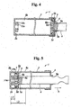
- Fig. 4 is a side sectional view showing the air damper in a state of beginning to open.
- Fig. 5 is a side sectional view showing the air damper in the fully open state; and
- Fig. 6 is a side sectional view showing the air damper in a state of beginning to close from the fully open state.
- Hereunder, embodiments of the present invention will be explained with reference to the accompanying drawings.
Fig. 1 is a side view showing essential components of an air damper 1 for anautomobile glove compartment 2 according to an embodiment of the present invention. Acylinder 3 of the air damper 1 is pivotally supported by means of an integrally formedarm 3a on a dashboard (not shown). A front end part (protruding end part) of apiston rod 4 protruding out from thecylinder 3 is linked in a suitable place of theglove compartment 2. Thepiston rod 4 is plunged into thecylinder 3 in a fully closed state of theglove compartment 2 shown by solid lines in the drawing. Thepiston rod 4 is protruding out to the longest or near that in the fully open state shown by phantom lines in the drawing. - The air damper 1 is used for opening and closing the
glove compartment 2. When theglove compartment 2 opens by its own weight, it opens gently by the damper effect, and when closing by a hand, it is closed lightly without resistance by the air damper 1. A structure of the air damper 1 for that purpose is not anything special. - For example as shown in Fig. 2 and Fig. 3, the air dumper 1 comprises the
cylinder 3 having a cylindrical shape with a bottom, apiston 5 received inside thecylinder 3 to move freely back and forth, and thepiston rod 4 which extends out coaxially on a side opposite to a bottom 3b of thecylinder 3. Aflat cap 6 having a cylindrical shape with a bottom is attached on the open end of thecylinder 3. Thepiston rod 4 extends through thatcap 6, and protrudes out coaxially to the outside of thecylinder 3. Also, thepiston rod 4 is supported to slide freely by an opening 6a provided in the center part of the end plate of thecap 6. - The
piston 5 is formed in a disk shape having a certain width in the axial direction. Acircumferential groove 5a having a flat U-shape in a cross sectional shape is formed over an entire outer perimeter of thepiston 5, and an O-ring 7 is fitted in thecircumferential groove 5a. A width of thecircumferential groove 5a (length in the axial direction of the piston 5) is a length by which the O-ring 7 can move in its width direction. - The
piston 5 is provided withaxial grooves 5b at an end portion thereof' on a side of thepiston rod 4. Theaxial grooves 5b are opened and reach near a mid-point in a width direction of thecircumferential groove 5a. Theaxial grooves 5b are provided such that, in a state that the 0-ring 7 is positioned in thecircumferential groove 5a where the piston rod protrudes outwardly, anair chamber 8a partitioned by thepiston 5 on the side opposite to the bottom 3b communicates with a part of thecircumferential grooves 5a not closed by the O-ring 7. In that communicating state, theair chamber 8a communicates with anair chamber 8b on the side of the bottom of thepiston 5. - When the
piston 5 is displaced in the direction indicated by the arrow A in Fig. 4, in which thepiston rod 4 protrudes outwardly, because the 0-ring 7 slides on the inner perimeter surface of thecylinder 3, it moves inside thecircumferential groove 5a toward the side of the bottom 3b as shown in Fig. 4. Accordingly, when the O-ring 7 is positioned between theair chamber 8b on the side of the bottom 3b and theaxial grooves 5b, the communicating state is blocked. - An
orifice 5c passing through in the axial direction is provided in thepiston 5 in a suitable place. Accordingly, in the blocked state by the O-ring 7 during displacement of thepiston 5 in the arrow A direction, air flows from theair chamber 8a to theair chamber 8b through theorifice 5c, whereby the air damper effect is exhibited. When thepiston 5 is displaced in the arrow A direction, thepiston rod 4 protrudes from thecylinder 3, that is, theglove compartment 2 is opened. Therefore, when opening theglove compartment 2, a gentle opening action by air damper can be accomplished. - In the fully open state of the
glove compartment 2, the air damper 1 becomes in a state in which thepiston rod 4 is maximally protruding as shown in Fig. 5. It is not necessary for thepiston 5 to contact thecap 6 when theglove compartment 2 is fully open, and it also may become in the maximally protruding state before that. - When closing the
glove compartment 2, thepiston rod 4 is displaced toward the direction of plunging into thecylinder 3 as shown by an arrow B in Fig. 6. The O-ring 7 slides on the inner perimeter surface of thecylinder 3 and moves inside thecircumferential groove 5a toward the side of thepiston rod 4. Accordingly, the twoair chambers piston 5 become in a communicating state by means of theaxial grooves 5b. Theaxial grooves 5b are provided at plural locations to increase a flow channel area. Accordingly, when thepiston rod 4 is moving in the plunging direction, the resistance of the air flowing between the twoair chambers - When the
glove compartment 2 opens by its own weight, the opening action can be accomplished gently by the air damper effect. In addition, when closing theglove compartment 2, it can be closed with light force in a manner such that air resistance is not caused by making the flow of air smooth, and the product quality in opening and closing of theglove compartment 2 can be increased. - Each component of the damper 1 can be made as a molded product from a synthetic resin material, thereby making the damper lightweight and reducing cost. In the case of resin molding, a solid thick part has a cutout portion so that sink or deformation does not occur. In the air damper 1, the
piston 5 has a certain thickness in the axial direction. Accordingly, as shown in Fig. 2, dualannular recess portions piston 5 as a cutout portion. - An annular rib spacing the two
annular recess portions orifice 5c, and the annular rib may be a shape continuing over the entire perimeter depending on a position of theorifice 5c. Theorifice 5c shown in Fig. 3 to Fig. 6 is just an example, and it does not specifically show its position. -
Annular walls annular recess portions cylinder 3. When thepiston 5 contacts the bottom 3a, air can accumulate inside theannular recess portions annular walls annular walls annular recess portions annular recess portions - When the
piston 5 starts to be displaced in the protruding direction of thepiston rod 4 from the maximally plunged state shown in Fig. 3, as shown in Fig. 4, an idling distance L1 due to expansion of air accumulated in the cutout parts of the piston becomes shorter than an idling distance L2 in a case that there are noannular walls - When an air damper is used in a
glove compartment 2 as in the present embodiment, if the idling distance is long at the start of opening, even if an degree of opening is small, it may open suddenly and be startling. When the idling distance is short or even virtually nonexistent, it opens gently from the start of opening, thereby preventing such startling and creating a sense of high quality. - In the embodiment, the dual
annular walls base 3a with rigidity as compared with one wall. Also, it is made in a shape in which they form concentric circles with respect to the axis. Accordingly, it is effective also when it is used in a manner such that thepiston 5 can rotate around the axis. - The shape of the protruding portions (
annular walls base 3a is an annular wall shape. They should be matched to the cutout shape on the side of thepiston 5, and are not limited to the annular walls. Also, the outer surface of thebase 3a of thecylinder 3 may be recessed. The protruding shape on the side of thebase 3a, as in the embodiment, is effective from a relationship between the parting surface and the core when molding thecylinder 3 having a cylindrical shape with a base. - The air damper according to the present invention has the effect of eliminating the idling distance due to air accumulation in cutouts provided in the piston, and it is useful as an air damper that can be applied to various kinds of opening-and-closing bodies.
- The disclosure of Japanese Patent Application No. 2004-207078, filed on July 14, 2004, is incorporated in the application.
Claims (8)
- An air damper (1), comprising:a cylinder (3) having a bottom portion, anda piston (5) disposed in the cylinder to move back and forth therein, and having a piston rod (4) extending toward a side opposite to the bottom portion (3a),said air damper (1) being characterized in that the piston (5) has a recess portion (9a, 9b) provided in an end portion facing the bottom portion, andsaid cylinder (3) has a protruding portion (10a, 10b) provided on the bottom portion to be inserted into the recess portion when the piston is fully inserted into the cylinder.
- An air damper (1) according to claim 1, wherein said piston (5) is formed of a synthetic resin material, and the recess portion is provided for preventing sink.
- An air damper (1) according to claim 1, wherein said protruding portion (10a, 10b) includes at least one arc rib or a circular rib extending coaxially with an axis of the cylinder.
- An air damper (1) according to claim 1, wherein said protruding portion (10a, 10b) includes a plurality of arc ribs or circular ribs formed concentrically relative to an axis of the cylinder.
- An air damper (1) according to claim 1, wherein said protruding portion (10a, 10b) has a shape corresponding to the recess portion (9a, 9b) so that the protruding portion is substantially completely located in the recess portion when the piston is fully inserted into the cylinder.
- An air damper (1) according to claim 5, wherein said piston has a circumferential groove (5a) at a side portion thereof, and at least one axial groove (5b) communicating with the circumferential groove and a side of the piston rod.
- An air damper (1) according to claim 6, further comprising an O-ring (7) disposed in the circumferential groove (5a) so that the O-ring can slide inside the circumferential groove upon movement of the piston.
- An air damper (1) according to claim 7, wherein said piston (5) further includes an orifice (5c).
Applications Claiming Priority (1)
| Application Number | Priority Date | Filing Date | Title |
|---|---|---|---|
| JP2004207078A JP4041812B2 (en) | 2004-07-14 | 2004-07-14 | Air damper |
Publications (2)
| Publication Number | Publication Date |
|---|---|
| EP1617099A1 true EP1617099A1 (en) | 2006-01-18 |
| EP1617099B1 EP1617099B1 (en) | 2009-01-21 |
Family
ID=34979906
Family Applications (1)
| Application Number | Title | Priority Date | Filing Date |
|---|---|---|---|
| EP05015267A Ceased EP1617099B1 (en) | 2004-07-14 | 2005-07-14 | Air damper |
Country Status (5)
| Country | Link |
|---|---|
| US (1) | US7353922B2 (en) |
| EP (1) | EP1617099B1 (en) |
| JP (1) | JP4041812B2 (en) |
| CN (2) | CN2869438Y (en) |
| DE (1) | DE602005012462D1 (en) |
Cited By (1)
| Publication number | Priority date | Publication date | Assignee | Title |
|---|---|---|---|---|
| FR2927135A1 (en) * | 2008-02-05 | 2009-08-07 | Dubourgel Grange Sa Ets | Mechanical piece's e.g. lid, pivoting movement limiting device for lavatory, has flow unit permitting limited flow of air in chamber or outside chamber for pivoting direction of piece, and shafts and pistons made of plastic material |
Families Citing this family (18)
| Publication number | Priority date | Publication date | Assignee | Title |
|---|---|---|---|---|
| JP4041812B2 (en) * | 2004-07-14 | 2008-02-06 | 本田技研工業株式会社 | Air damper |
| US20070237661A1 (en) * | 2006-04-05 | 2007-10-11 | Tsun-Sheng Chen | Hand-operated reciprocating pump |
| JP5022106B2 (en) * | 2007-03-30 | 2012-09-12 | 株式会社ニフコ | Damper device |
| JP5048453B2 (en) * | 2007-10-25 | 2012-10-17 | 株式会社ニフコ | Damper and door handle with this damper |
| JP5141462B2 (en) * | 2008-09-16 | 2013-02-13 | 株式会社リコー | Storage structure and image forming apparatus |
| US8240329B1 (en) | 2008-11-14 | 2012-08-14 | Robust Systems Solutions, LLC | Fluid control valve |
| CN101598156B (en) * | 2009-06-17 | 2012-03-14 | 江苏恒立高压油缸股份有限公司 | Floating-type cushion cylinder |
| US9239170B2 (en) | 2010-11-04 | 2016-01-19 | Air Divide, Llc | Integrated self-contained plenum module |
| FR2971029B1 (en) * | 2011-01-31 | 2013-01-18 | Eurocopter France | IMPROVED TRAINING DAMPING DEVICE |
| US8934948B2 (en) | 2011-04-22 | 2015-01-13 | Blackberry Limited | Low profile air damper |
| JP5844143B2 (en) * | 2011-12-27 | 2016-01-13 | 株式会社ニフコ | Air damper |
| DE102014111618A1 (en) * | 2014-08-14 | 2016-02-18 | Dr. Ing. H.C. F. Porsche Aktiengesellschaft | Air damper for a storage compartment cover of a motor vehicle and method for operating a storage space cover of a motor vehicle |
| DE102014216949A1 (en) * | 2014-08-26 | 2016-03-03 | Continental Teves Ag & Co. Ohg | steamers |
| KR101867172B1 (en) * | 2015-09-18 | 2018-06-12 | 가부시키가이샤 니프코 | Damper |
| CN111852232B (en) * | 2020-07-03 | 2025-08-12 | 广东精诺五金实业有限公司 | Damper and damping hinge |
| CN111852235B (en) * | 2020-07-03 | 2025-11-14 | 广东精诺五金实业有限公司 | A damping hinge |
| JP7481993B2 (en) * | 2020-10-23 | 2024-05-13 | 株式会社パイオラックス | Damper Device |
| KR102684046B1 (en) * | 2022-04-04 | 2024-07-12 | 현대모비스 주식회사 | Damper for glove box in vehicle and glove box having the same |
Citations (7)
| Publication number | Priority date | Publication date | Assignee | Title |
|---|---|---|---|---|
| US4166612A (en) * | 1976-04-30 | 1979-09-04 | Stabilus Gmbh | Gas spring with means for impeding piston movement away from one terminal position |
| US4500075A (en) * | 1980-12-18 | 1985-02-19 | Matsushita Electric Industrial Co., Ltd. | Air pressure shock absorber |
| US4741518A (en) * | 1986-08-26 | 1988-05-03 | Wallis Bernard J | Self contained gas spring interchangeable with coil spring |
| JPH02129424A (en) * | 1988-11-07 | 1990-05-17 | Nifco Inc | Cylinder type air damper |
| JPH08105482A (en) | 1994-10-07 | 1996-04-23 | Nifco Inc | Air damper |
| US20010007297A1 (en) * | 2000-01-11 | 2001-07-12 | Itw Automotive Products Gmbh & Co Kg | Air damper for movable elements, in particular in automobiles |
| JP2004207078A (en) | 2002-12-25 | 2004-07-22 | Seiko Epson Corp | Display panel and manufacturing method thereof |
Family Cites Families (10)
| Publication number | Priority date | Publication date | Assignee | Title |
|---|---|---|---|---|
| US3040712A (en) * | 1959-04-17 | 1962-06-26 | Firco Inc | Cylinder, piston and rod assembly |
| DE1775416B2 (en) * | 1968-08-08 | 1971-12-30 | Stabilus Industrie und Handelsge Seilschaft mbH, 5400 Koblenz | GAS SPRING WITH VIBRATION DAMPING ESPECIALLY FOR AIRPLANE SUSPENSION STRUTS |
| DE2516478C3 (en) * | 1975-04-15 | 1978-12-07 | Suspa-Federungstechnik Fritz Bauer & Soehne Ohg, 8503 Altdorf | Gas spring |
| US4110868A (en) * | 1976-02-23 | 1978-09-05 | Yasutaka Imazaike | Air damper |
| DE3937306A1 (en) * | 1989-11-09 | 1991-05-16 | Friedhelm Steinhilber | HYDRAULIC TELESCOPIC DAMPER |
| US5275387A (en) * | 1992-04-09 | 1994-01-04 | Power Components, Inc. | Gas spring |
| DE10021762B4 (en) | 2000-05-04 | 2006-03-16 | Itw-Ateco Gmbh | Air damper for a movably mounted component, in particular in automobiles |
| JP3912966B2 (en) | 2000-08-25 | 2007-05-09 | 株式会社パイオラックス | Air damper |
| JP2002146861A (en) | 2000-11-14 | 2002-05-22 | Piolax Inc | Return delay device |
| JP4041812B2 (en) * | 2004-07-14 | 2008-02-06 | 本田技研工業株式会社 | Air damper |
-
2004
- 2004-07-14 JP JP2004207078A patent/JP4041812B2/en not_active Expired - Fee Related
-
2005
- 2005-07-12 US US11/178,388 patent/US7353922B2/en not_active Expired - Lifetime
- 2005-07-13 CN CNU200520113513XU patent/CN2869438Y/en not_active Expired - Fee Related
- 2005-07-13 CN CN200510083156.1A patent/CN1721726B/en not_active Expired - Fee Related
- 2005-07-14 EP EP05015267A patent/EP1617099B1/en not_active Ceased
- 2005-07-14 DE DE602005012462T patent/DE602005012462D1/en not_active Expired - Lifetime
Patent Citations (7)
| Publication number | Priority date | Publication date | Assignee | Title |
|---|---|---|---|---|
| US4166612A (en) * | 1976-04-30 | 1979-09-04 | Stabilus Gmbh | Gas spring with means for impeding piston movement away from one terminal position |
| US4500075A (en) * | 1980-12-18 | 1985-02-19 | Matsushita Electric Industrial Co., Ltd. | Air pressure shock absorber |
| US4741518A (en) * | 1986-08-26 | 1988-05-03 | Wallis Bernard J | Self contained gas spring interchangeable with coil spring |
| JPH02129424A (en) * | 1988-11-07 | 1990-05-17 | Nifco Inc | Cylinder type air damper |
| JPH08105482A (en) | 1994-10-07 | 1996-04-23 | Nifco Inc | Air damper |
| US20010007297A1 (en) * | 2000-01-11 | 2001-07-12 | Itw Automotive Products Gmbh & Co Kg | Air damper for movable elements, in particular in automobiles |
| JP2004207078A (en) | 2002-12-25 | 2004-07-22 | Seiko Epson Corp | Display panel and manufacturing method thereof |
Non-Patent Citations (1)
| Title |
|---|
| PATENT ABSTRACTS OF JAPAN vol. 014, no. 364 (M - 1007) 7 August 1990 (1990-08-07) * |
Cited By (1)
| Publication number | Priority date | Publication date | Assignee | Title |
|---|---|---|---|---|
| FR2927135A1 (en) * | 2008-02-05 | 2009-08-07 | Dubourgel Grange Sa Ets | Mechanical piece's e.g. lid, pivoting movement limiting device for lavatory, has flow unit permitting limited flow of air in chamber or outside chamber for pivoting direction of piece, and shafts and pistons made of plastic material |
Also Published As
| Publication number | Publication date |
|---|---|
| EP1617099B1 (en) | 2009-01-21 |
| CN1721726A (en) | 2006-01-18 |
| CN1721726B (en) | 2010-04-21 |
| US20060011431A1 (en) | 2006-01-19 |
| CN2869438Y (en) | 2007-02-14 |
| JP2006029406A (en) | 2006-02-02 |
| US7353922B2 (en) | 2008-04-08 |
| DE602005012462D1 (en) | 2009-03-12 |
| JP4041812B2 (en) | 2008-02-06 |
Similar Documents
| Publication | Publication Date | Title |
|---|---|---|
| EP1617099B1 (en) | Air damper | |
| US5884734A (en) | Air damper | |
| US5471708A (en) | Pneumatic door closer | |
| US5632474A (en) | Compact hydraulic autotensioner with return spring mounted around a sleeve | |
| US6968930B2 (en) | Damper | |
| JP2695021B2 (en) | Furniture hinge | |
| EP1152165B1 (en) | Air damper for a movably supported structural part, in particular in automobiles | |
| US4856625A (en) | Cylinder type air damper with filter for storage box | |
| JP2009528490A (en) | Furniture damper | |
| KR20210043451A (en) | Damping valve device for a vibration damper | |
| JP4842431B2 (en) | Air damper with adjustable air flow speed | |
| CN218440380U (en) | Damper for glove box and glove box with damper | |
| JP2010265990A (en) | Air damper | |
| JPH08105482A (en) | Air damper | |
| JP2006046660A (en) | Gas spring | |
| JPH09217773A (en) | gas spring | |
| EP1182373B1 (en) | Air damper used in glove box of automobile | |
| US20070145760A1 (en) | Vehicle door container holder | |
| JP3234724B2 (en) | Air damper | |
| JPH08105481A (en) | Air damper | |
| JPH06288404A (en) | Linear drive | |
| JP3813290B2 (en) | Exhaust muffler with built-in valve for automobile | |
| US20240035538A1 (en) | Damper device | |
| JPH0567840U (en) | Piston cylinder type damper | |
| KR0128034Y1 (en) | Adjustable gas spring in the car |
Legal Events
| Date | Code | Title | Description |
|---|---|---|---|
| PUAI | Public reference made under article 153(3) epc to a published international application that has entered the european phase |
Free format text: ORIGINAL CODE: 0009012 |
|
| AK | Designated contracting states |
Kind code of ref document: A1 Designated state(s): AT BE BG CH CY CZ DE DK EE ES FI FR GB GR HU IE IS IT LI LT LU LV MC NL PL PT RO SE SI SK TR |
|
| AX | Request for extension of the european patent |
Extension state: AL BA HR MK YU |
|
| 17P | Request for examination filed |
Effective date: 20060714 |
|
| 17Q | First examination report despatched |
Effective date: 20060810 |
|
| AKX | Designation fees paid |
Designated state(s): DE GB |
|
| GRAP | Despatch of communication of intention to grant a patent |
Free format text: ORIGINAL CODE: EPIDOSNIGR1 |
|
| GRAS | Grant fee paid |
Free format text: ORIGINAL CODE: EPIDOSNIGR3 |
|
| GRAS | Grant fee paid |
Free format text: ORIGINAL CODE: EPIDOSNIGR3 |
|
| GRAA | (expected) grant |
Free format text: ORIGINAL CODE: 0009210 |
|
| AK | Designated contracting states |
Kind code of ref document: B1 Designated state(s): DE GB |
|
| REG | Reference to a national code |
Ref country code: GB Ref legal event code: FG4D |
|
| REF | Corresponds to: |
Ref document number: 602005012462 Country of ref document: DE Date of ref document: 20090312 Kind code of ref document: P |
|
| PLBE | No opposition filed within time limit |
Free format text: ORIGINAL CODE: 0009261 |
|
| STAA | Information on the status of an ep patent application or granted ep patent |
Free format text: STATUS: NO OPPOSITION FILED WITHIN TIME LIMIT |
|
| 26N | No opposition filed |
Effective date: 20091022 |
|
| REG | Reference to a national code |
Ref country code: DE Ref legal event code: R082 Ref document number: 602005012462 Country of ref document: DE Representative=s name: DR. GASSNER & PARTNER MBB PATENTANWAELTE, DE Ref country code: DE Ref legal event code: R081 Ref document number: 602005012462 Country of ref document: DE Owner name: NIFCO INC., YOKOSUKA-SHI, JP Free format text: FORMER OWNER: NIFCO INC., HONDA MOTOR CO., LTD., , JP Ref country code: DE Ref legal event code: R081 Ref document number: 602005012462 Country of ref document: DE Owner name: NIFCO INC., YOKOSUKA-SHI, JP Free format text: FORMER OWNERS: NIFCO INC., YOKOHAMA, KANAGAWA-SHI, JP; HONDA MOTOR CO., LTD., TOKYO, JP |
|
| REG | Reference to a national code |
Ref country code: GB Ref legal event code: 732E Free format text: REGISTERED BETWEEN 20161103 AND 20161109 |
|
| PGFP | Annual fee paid to national office [announced via postgrant information from national office to epo] |
Ref country code: GB Payment date: 20190710 Year of fee payment: 15 |
|
| PGFP | Annual fee paid to national office [announced via postgrant information from national office to epo] |
Ref country code: DE Payment date: 20200630 Year of fee payment: 16 |
|
| GBPC | Gb: european patent ceased through non-payment of renewal fee |
Effective date: 20200714 |
|
| PG25 | Lapsed in a contracting state [announced via postgrant information from national office to epo] |
Ref country code: GB Free format text: LAPSE BECAUSE OF NON-PAYMENT OF DUE FEES Effective date: 20200714 |
|
| REG | Reference to a national code |
Ref country code: DE Ref legal event code: R119 Ref document number: 602005012462 Country of ref document: DE |
|
| PG25 | Lapsed in a contracting state [announced via postgrant information from national office to epo] |
Ref country code: DE Free format text: LAPSE BECAUSE OF NON-PAYMENT OF DUE FEES Effective date: 20220201 |