EP1617049B1 - Oil pan of internal combustion engine - Google Patents
Oil pan of internal combustion engine Download PDFInfo
- Publication number
- EP1617049B1 EP1617049B1 EP05253871A EP05253871A EP1617049B1 EP 1617049 B1 EP1617049 B1 EP 1617049B1 EP 05253871 A EP05253871 A EP 05253871A EP 05253871 A EP05253871 A EP 05253871A EP 1617049 B1 EP1617049 B1 EP 1617049B1
- Authority
- EP
- European Patent Office
- Prior art keywords
- oil
- oil pan
- pan
- combustion engine
- internal combustion
- Prior art date
- Legal status (The legal status is an assumption and is not a legal conclusion. Google has not performed a legal analysis and makes no representation as to the accuracy of the status listed.)
- Ceased
Links
- 238000002485 combustion reaction Methods 0.000 title claims description 31
- 238000003780 insertion Methods 0.000 claims description 10
- 230000037431 insertion Effects 0.000 claims description 10
- XLYOFNOQVPJJNP-UHFFFAOYSA-N water Substances O XLYOFNOQVPJJNP-UHFFFAOYSA-N 0.000 claims description 5
- 238000001816 cooling Methods 0.000 claims description 4
- 239000000498 cooling water Substances 0.000 claims description 4
- 239000003921 oil Substances 0.000 description 251
- 230000001050 lubricating effect Effects 0.000 description 8
- 230000006866 deterioration Effects 0.000 description 3
- 238000005461 lubrication Methods 0.000 description 3
- 239000003595 mist Substances 0.000 description 3
- 238000012986 modification Methods 0.000 description 2
- 230000004048 modification Effects 0.000 description 2
- 230000001133 acceleration Effects 0.000 description 1
- 230000005855 radiation Effects 0.000 description 1
Images


Classifications
-
- F—MECHANICAL ENGINEERING; LIGHTING; HEATING; WEAPONS; BLASTING
- F01—MACHINES OR ENGINES IN GENERAL; ENGINE PLANTS IN GENERAL; STEAM ENGINES
- F01M—LUBRICATING OF MACHINES OR ENGINES IN GENERAL; LUBRICATING INTERNAL COMBUSTION ENGINES; CRANKCASE VENTILATING
- F01M11/00—Component parts, details or accessories, not provided for in, or of interest apart from, groups F01M1/00 - F01M9/00
- F01M11/02—Arrangements of lubricant conduits
-
- F—MECHANICAL ENGINEERING; LIGHTING; HEATING; WEAPONS; BLASTING
- F01—MACHINES OR ENGINES IN GENERAL; ENGINE PLANTS IN GENERAL; STEAM ENGINES
- F01M—LUBRICATING OF MACHINES OR ENGINES IN GENERAL; LUBRICATING INTERNAL COMBUSTION ENGINES; CRANKCASE VENTILATING
- F01M11/00—Component parts, details or accessories, not provided for in, or of interest apart from, groups F01M1/00 - F01M9/00
- F01M11/0004—Oilsumps
-
- F—MECHANICAL ENGINEERING; LIGHTING; HEATING; WEAPONS; BLASTING
- F01—MACHINES OR ENGINES IN GENERAL; ENGINE PLANTS IN GENERAL; STEAM ENGINES
- F01M—LUBRICATING OF MACHINES OR ENGINES IN GENERAL; LUBRICATING INTERNAL COMBUSTION ENGINES; CRANKCASE VENTILATING
- F01M11/00—Component parts, details or accessories, not provided for in, or of interest apart from, groups F01M1/00 - F01M9/00
- F01M11/0004—Oilsumps
- F01M2011/0033—Oilsumps with special means for guiding the return of oil into the sump
-
- F—MECHANICAL ENGINEERING; LIGHTING; HEATING; WEAPONS; BLASTING
- F01—MACHINES OR ENGINES IN GENERAL; ENGINE PLANTS IN GENERAL; STEAM ENGINES
- F01M—LUBRICATING OF MACHINES OR ENGINES IN GENERAL; LUBRICATING INTERNAL COMBUSTION ENGINES; CRANKCASE VENTILATING
- F01M11/00—Component parts, details or accessories, not provided for in, or of interest apart from, groups F01M1/00 - F01M9/00
- F01M11/02—Arrangements of lubricant conduits
- F01M2011/023—Arrangements of lubricant conduits between oil sump and cylinder head
Definitions
- the present invention relates to an internal combustion engine comprising an oil pan.
- Oil for lubricating respective sliding portions of an internal combustion engine is deposited in the oil pan of the internal combustion engine and supplied to those respective sliding portions of the internal combustion engine by means of an oil pump and the like through an oil strainer.
- oil After lubricating a sliding surface between a cylinder and a piston and bearings of a connecting rod and crank shaft of the sliding portions of the internal combustion engine, oil floats in the condition of mist within a crank case and receiving heat from blow-by gas at high temperatures leaking from the sliding surface between the cylinder and the piston, drops onto a baffle plate so that it is returned to the oil pan.
- An oil pan constituted such that head-side and block-side oil passages conduct oil to the oil collection chamber from the cylinder head and cylinder block is revealed in JP 2002-021520 , upon which the precharacterising portion of claim 1 is based.
- Japanese Utility Model Application Laid-Open NO.HEI4-71716 has been proposed in order to prevent the oil strainer from being exposed over oil surface and sucking air due to tilt of the oil surface generated at the time of acceleration or deceleration for startup or stop of a vehicle or turning and stably supply the oil to the respective sliding portions of the internal combustion engine, thereby improving wear resistance.
- a lidded cylindrical baffle plate for defining an oil holding space to surround the oil strainer is provided on an oil sump within the oil pan and this lidded cylindrical baffle plate has a communicating opening hole which communicates with the interior of the oil pan and in which the oil strainer is inserted at its lid portion and a dent portion which communicates with the interior of the oil pan at the bottom of this cylindrical body. Consequently, by holding sufficient amount of oil within the oil holding space by this cylindrical body even when oil surface is tilted, oil can be supplied to the respective sliding portions of the internal combustion engine stably.
- the internal combustion engine comprising an oil pan of the present invention intends to prevent a drop in the viscosity of oil and deterioration of the oil, to improve the lubrication performance thereof, by cooling the oil within the oil pan to equalize the temperature of the oil.
- an internal combustion engine comprising an oil pan said oil pan being mountable on a bottom part of a crank case of the internal combustion engine which includes a first oil return passage which is stretched from a cylinder head to the oil pan through the crank case and a baffle plate, and a second oil return passage which is stretched from the cylinder head to the oil pan, the oil pan being for collecting oil returned from said first oil return passage and said second oil return passage, said oil pan being characterised by: an oil introducing means comprising: an oil introduction plate containing an insertion hole through which a sucking portion of an oil strainer is to be inserted said oil introduction plate extending from around said insertion hole toward the side wall of said oil pan; a plurality of inclined wall portions mounted on the oil pan bottom portion in the vicinity of the side wall of said oil pan to support said oil introduction plate; and opening portions formed in the inclined wall portions; wherein the oil introduction plate is located within the oil pan and just below an oil falling hole formed in said baffle plate of said internal combustion engine.
- the oil introducing means is provided with sheet-like jaw portions at the top end of the opening portions.
- the bottom end of the second oil return passage is open in conditions in which it is submerged in oil collected within the oil pan and part of the opening portion in the oil introducing means is open toward the bottom end of the second oil return passage.
- said second oil return passage is formed vertically on the outer periphery side of a water jacket in which cooling water for cooling a cylinder flows.
- the present invention provides an internal combustion engine comprising an oil pan, said oil pan being mounted on a bottom part of a crank case including a first oil return passage stretched from a cylinder head to the oil pan through a crank case and a baffle plate and a second oil return passage stretched from the cylinder head to the oil pan and for collecting oil returned from the first oil return passage and the second oil return passage.
- the oil pan of internal combustion engine further includes an oil introducing means containing an insertion hole which a sucking portion of an oil strainer is to be inserted through and further comprised of: an oil introducing plate extended from around the insertion hole toward the side wall of the oil pan to introduce oil returned from the first oil return passage; a plurality of inclined wall portions mounted on the oil pan bottom portion in the vicinity of the side wall of the oil pan to support the oil introducing plate; and opening portions formed in the inclined wall portions, the oil introducing plate of the oil introducing means being located within the oil pan and just below an oil falling hole formed in the baffle plate.
- hot oil flowing down from the first oil return passage is introduced to the side wall of the oil pan along the oil introducing plate of the oil introducing means and can be cooled excellently by the side wall of the oil pan which keeps in contact with the atmosphere. Further, by introducing oil toward the side wall, entire oil within the oil pan is circulated, thereby eliminating oil retaining zone in the oil pan. Further, the temperature of the oil in the oil pan is equalized excellently and that oil is introduced to the sucking portion of the oil strainer through the opening portions in the inclined wall portions of the oil introducing means and can be supplied to respective portions of the internal combustion engine excellently. As a result, drop in the viscosity of oil and deterioration of the oil can be prevented.
- the oil introducing means is provided on the bottom of the oil pan and the oil introducing plate contains the insertion hole which the sucking portion of the oil strainer is to be inserted through, the oil introducing means can be fixed on the bottom of the oil pan excellently and further, the oil strainer can be installed on the oil introducing means compactly.
- the oil introducing means is provided with sheet-like jaw portions at the top end of the opening portions, hot oil flowing down from the first oil return passage runs over a long distance on the jaw portion and introduced to the side wall of the oil pan excellently.
- fluidity of oil in the oil pan is improved thereby eliminating the oil retaining zone and further by feeding oil along the side wall of the oil pan, active radiation of heat to the atmosphere is enabled.
- the bottom end of the second oil return passage is open in conditions in which it is submerged in oil collected within the oil pan and part of the opening portion in the oil introducing means is open toward the bottom end of the second oil return passage
- hot oil flowing down from the first oil return passage runs to the side wall of the oil pan along the oil introducing plate of the oil introducing means and cooled by the side wall and then introduced to the sucking portion of the oil strainer through the opening portion in the oil introducing means.
- cooled oil introduced from the cylinder head flows down from the bottom end of the second oil return passage into the oil pan and flows toward the opening portion of the oil introducing means.
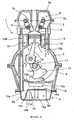
- FIG. 1 is a longitudinal sectional view of the internal combustion engine.
- a cylinder head 3 is provided on the top of a cylinder block 2 and a crank case 4 is connected to the bottom of the cylinder block 2.
- An oil pan 5 for collecting oil is provided below the crank case 4.
- a head cover 3a is mounted on the top of the cylinder head 3 to cover valve driving parts such as cam shafts 7a, cams 7b and valve springs 8 provided within the cylinder head 3, and the cylinder head 3 and the head cover 3a constitute a cam chamber 6.
- a piston 9 and a connecting rod 10 are provided within the cylinder block 2 and a crank shaft 11 and a counterweight 12 are provided within the crank case 4.
- the counterweight 12 rotates in the direction indicated with an arrow.
- a curved baffle plate 13 is provided along a rotary trajectory of the counterweight 12 of the crank shaft 11 on the bottom of the crank case 4.
- Oil lubricating the sliding surface between the cylinder and piston and oil lubricating the valve driving parts such as the cam shaft 7a, the cam 7b and the valve spring 8 in one section of the cylinder head 3 drop into the crank case, thereby lubricating the connecting rod 10, the crank shaft 11 and the like and are returned into the oil pan 5 located below through oil falling holes 13a, 13a, 13b formed in the baffle plate 13.
- a water jacket 14 in which cooling water for cooling the cylinder flows is provided sideway of the piston 9 within the cylinder block 2 and a second oil return passage 15B is formed vertically on the outer periphery side of that water jacket 14.
- This second oil return passage 15B is constructed of the cylinder head 3, the cylinder block 2 and the crank case 4 to return oil lubricating the valve driving parts such as the cam shaft 7a, the cam 7b and the valve spring 8 in the other section of the cylinder head 3 to the oil pan 5 and formed in the vertical direction of the internal combustion engine.
- a bottom end opening portion 15a of the second oil return passage 15B is located at a position submerged in oil collected within the oil pan 5.
- Oil returned to the oil pan 5 through the second oil return passage 15B is cooled by cooling water flowing through the water jacket 14 halfway of the return, to a low temperature and returned into the oil pan 5.
- the oil lubricating the sliding surface between the cylinder and the piston 9 and the oil lubricating the valve driving parts such as the cam shaft 7a, the cam 7b and the valve spring 8 in the one section of the cylinder head 3 lubricate the connecting rod 10, the crank shaft 11 and the like and at the same time, are splashed by the connecting rod 10, the counterweight 12 and the like rotated at high speeds when the internal combustion engine is operated, so that the oil turns into mist whose surface area per unit volume is large, thereby increasing the quantity of heat received from hot blow-by gas leaking from the sliding surface between the cylinder and the piston 9 and as a consequence, the temperature of the mist gas is kept high.
- This hot oil is returned to the oil pan 5 through the oil falling holes 13a, 13b in the baffle plate 13 as described previously.
- an oil introducing means 16 is provided within the oil pan 5.
- the oil introducing means 16 is fixed on a bottom wall 5b of the oil pan 5 and comprised of an oil introducing plate 16a, inclined wall portions 16b and fixing pieces 16c to be fixed on the bottom wall 5b of the oil pan 5.
- An insertion hole 16d in which an oil strainer 18 is to be installed is made in the center of the oil introducing plate 16a.
- a sucking portion 18a which is a bottom end of the oil strainer 18 is inserted through the insertion hole 16d in the center of the oil introducing plate 16 and disposed in the vicinity of the bottom wall 5b of the oil pan 5 located below.
- An oil passage for feeding oil to an oil pump (not shown) is provided in the top face of the oil strainer 18.
- the oil introducing means 16 is provided so as to surround the sucking portion 18a of the oil strainer 18 and the oil introducing plate 16a of this oil introducing means 16 is extended from around the insertion hole 16d toward the side wall of the oil pan and disposed just below the oil falling hole 13b located at the lowest position of the baffle plate 13.
- drain side opening portions 17a, 17a are formed in the inclined wall portion 16b of the oil introducing means 16 such that they are directed to the bottom end opening 15a of the second oil return passage 15B and the drain side opening portions 17a, 17a are preferred to be made in the vicinity of the bottom end opening 15a of the second oil return passage 15B.
- a rear side opening portion 17b is formed on an opposite side to the drain side opening portion 17a in the inclined wall portion 16b.
- cooled oil flows out from the bottom end opening 15a through the second oil return passage 15B and can flow into the oil introducing means 16 through the drain side opening portions 17a, 17a.
- Hot oil dropping on the oil introducing plate 16a of the oil introducing means 16 flows to the side wall 5a of the oil pan 5 along the oil introducing plate 16a. Because the side wall 5a of this oil pan 5 keeps contact with the atmosphere, while hot oil flows to the bottom wall 5b along the side wall 5a, heat is radiated excellently to the atmosphere so that the temperature of oil is reduced. With the temperature dropping gradually, the oil flows into the oil introducing means 16 through the drain side opening portion 17a and the rear side opening portion 17b.
- FIG. 3 shows a modification of the oil introducing means 16.
- sheet-like jaw portions 16e, 16e, 16e are formed above the opening portions 17a, 17a, 17a so that they are projected toward the side wall 5a of the oil pan 5.
Landscapes
- Engineering & Computer Science (AREA)
- Mechanical Engineering (AREA)
- General Engineering & Computer Science (AREA)
- Lubrication Details And Ventilation Of Internal Combustion Engines (AREA)
- Lubrication Of Internal Combustion Engines (AREA)
- Cylinder Crankcases Of Internal Combustion Engines (AREA)
Description
- The present invention relates to an internal combustion engine comprising an oil pan.
- Oil for lubricating respective sliding portions of an internal combustion engine is deposited in the oil pan of the internal combustion engine and supplied to those respective sliding portions of the internal combustion engine by means of an oil pump and the like through an oil strainer.
- After lubricating a sliding surface between a cylinder and a piston and bearings of a connecting rod and crank shaft of the sliding portions of the internal combustion engine, oil floats in the condition of mist within a crank case and receiving heat from blow-by gas at high temperatures leaking from the sliding surface between the cylinder and the piston, drops onto a baffle plate so that it is returned to the oil pan.
- An oil pan constituted such that head-side and block-side oil passages conduct oil to the oil collection chamber from the cylinder head and cylinder block is revealed in
JP 2002-021520 - As regards the internal combustion engine, a structure as disclosed in for example, Japanese Utility Model Application Laid-Open NO.HEI4-71716 has been proposed in order to prevent the oil strainer from being exposed over oil surface and sucking air due to tilt of the oil surface generated at the time of acceleration or deceleration for startup or stop of a vehicle or turning and stably supply the oil to the respective sliding portions of the internal combustion engine, thereby improving wear resistance.
- According to the structure disclosed in this document, a lidded cylindrical baffle plate for defining an oil holding space to surround the oil strainer is provided on an oil sump within the oil pan and this lidded cylindrical baffle plate has a communicating opening hole which communicates with the interior of the oil pan and in which the oil strainer is inserted at its lid portion and a dent portion which communicates with the interior of the oil pan at the bottom of this cylindrical body. Consequently, by holding sufficient amount of oil within the oil holding space by this cylindrical body even when oil surface is tilted, oil can be supplied to the respective sliding portions of the internal combustion engine stably.
- However, the structure of such oil pan allows hot oil recovered after floating within the crank case to enter into the oil holding space through the communicating opening hole formed in the lid portion on the top of the baffle plate and consequently, the hot oil is supplied to the respective sliding portions of the internal combustion engine from the oil strainer, thereby possibly badly affecting the lubrication performance.
- The internal combustion engine comprising an oil pan of the present invention intends to prevent a drop in the viscosity of oil and deterioration of the oil, to improve the lubrication performance thereof, by cooling the oil within the oil pan to equalize the temperature of the oil.
- According to a first aspect of the present invention, there is provided an internal combustion engine comprising an oil pan said oil pan being mountable on a bottom part of a crank case of the internal combustion engine which includes a first oil return passage which is stretched from a cylinder head to the oil pan through the crank case and a baffle plate, and a second oil return passage which is stretched from the cylinder head to the oil pan, the oil pan being for collecting oil returned from said first oil return passage and said second oil return passage, said oil pan being characterised by: an oil introducing means comprising: an oil introduction plate containing an insertion hole through which a sucking portion of an oil strainer is to be inserted said oil introduction plate extending from around said insertion hole toward the side wall of said oil pan; a plurality of inclined wall portions mounted on the oil pan bottom portion in the vicinity of the side wall of said oil pan to support said oil introduction plate; and opening portions formed in the inclined wall portions; wherein the oil introduction plate is located within the oil pan and just below an oil falling hole formed in said baffle plate of said internal combustion engine.
- According to a second aspect of the present invention, the oil introducing means is provided with sheet-like jaw portions at the top end of the opening portions.
- According to a third aspect of the present invention, the bottom end of the second oil return passage is open in conditions in which it is submerged in oil collected within the oil pan and part of the opening portion in the oil introducing means is open toward the bottom end of the second oil return passage.
- According to a fourth aspect of the present invention, said second oil return passage is formed vertically on the outer periphery side of a water jacket in which cooling water for cooling a cylinder flows.
- The present invention provides an internal combustion engine comprising an oil pan, said oil pan being mounted on a bottom part of a crank case including a first oil return passage stretched from a cylinder head to the oil pan through a crank case and a baffle plate and a second oil return passage stretched from the cylinder head to the oil pan and for collecting oil returned from the first oil return passage and the second oil return passage. The oil pan of internal combustion engine further includes an oil introducing means containing an insertion hole which a sucking portion of an oil strainer is to be inserted through and further comprised of: an oil introducing plate extended from around the insertion hole toward the side wall of the oil pan to introduce oil returned from the first oil return passage; a plurality of inclined wall portions mounted on the oil pan bottom portion in the vicinity of the side wall of the oil pan to support the oil introducing plate; and opening portions formed in the inclined wall portions, the oil introducing plate of the oil introducing means being located within the oil pan and just below an oil falling hole formed in the baffle plate. As a consequence, hot oil flowing down from the first oil return passage is introduced to the side wall of the oil pan along the oil introducing plate of the oil introducing means and can be cooled excellently by the side wall of the oil pan which keeps in contact with the atmosphere. Further, by introducing oil toward the side wall, entire oil within the oil pan is circulated, thereby eliminating oil retaining zone in the oil pan. Further, the temperature of the oil in the oil pan is equalized excellently and that oil is introduced to the sucking portion of the oil strainer through the opening portions in the inclined wall portions of the oil introducing means and can be supplied to respective portions of the internal combustion engine excellently. As a result, drop in the viscosity of oil and deterioration of the oil can be prevented.
- Because the oil introducing means is provided on the bottom of the oil pan and the oil introducing plate contains the insertion hole which the sucking portion of the oil strainer is to be inserted through, the oil introducing means can be fixed on the bottom of the oil pan excellently and further, the oil strainer can be installed on the oil introducing means compactly.
- Because the oil introducing means is provided with sheet-like jaw portions at the top end of the opening portions, hot oil flowing down from the first oil return passage runs over a long distance on the jaw portion and introduced to the side wall of the oil pan excellently. As a consequence, fluidity of oil in the oil pan is improved thereby eliminating the oil retaining zone and further by feeding oil along the side wall of the oil pan, active radiation of heat to the atmosphere is enabled.
- Further, because the bottom end of the second oil return passage is open in conditions in which it is submerged in oil collected within the oil pan and part of the opening portion in the oil introducing means is open toward the bottom end of the second oil return passage, hot oil flowing down from the first oil return passage runs to the side wall of the oil pan along the oil introducing plate of the oil introducing means and cooled by the side wall and then introduced to the sucking portion of the oil strainer through the opening portion in the oil introducing means. At this time, cooled oil introduced from the cylinder head flows down from the bottom end of the second oil return passage into the oil pan and flows toward the opening portion of the oil introducing means. As a consequence, hot oil and cooled oil flowing down from the second oil return passage are mixed excellently so as to equalize and reduce the temperature of entire oil in the oil pan. Further, due to the mixing of the hot oil and the cooled oil, a positive tide is generated in entire oil within the oil pan, so that oil retaining zone in the oil pan diminishes and consequently, the temperature of the oil can be equalized further excellently.
- The invention will now be further described, by way of example only, with reference to the accompanying drawings, in which:-
-
FIG. 1 is a schematic longitudinal sectional view of the internal combustion engine; -
FIG. 2 is an enlarged perspective view of major portions in case where an oil introducing means is provided within an oil pan of the internal combustion engine; and -
FIG. 3 is an enlarged perspective view of major portions showing a modification of the oil introducing means. - Hereinafter, the preferred embodiment of the present invention will be described with reference to the accompanying drawings,
-
FIG. 1 is a longitudinal sectional view of the internal combustion engine. In the internal combustion engine 1, acylinder head 3 is provided on the top of acylinder block 2 and acrank case 4 is connected to the bottom of thecylinder block 2. Anoil pan 5 for collecting oil is provided below thecrank case 4. - A
head cover 3a is mounted on the top of thecylinder head 3 to cover valve driving parts such ascam shafts 7a,cams 7b andvalve springs 8 provided within thecylinder head 3, and thecylinder head 3 and thehead cover 3a constitute acam chamber 6. - A
piston 9 and a connectingrod 10 are provided within thecylinder block 2 and acrank shaft 11 and acounterweight 12 are provided within thecrank case 4. When the internal combustion engine is operating, thecounterweight 12 rotates in the direction indicated with an arrow. - A
curved baffle plate 13 is provided along a rotary trajectory of thecounterweight 12 of thecrank shaft 11 on the bottom of thecrank case 4. Oil lubricating the sliding surface between the cylinder and piston and oil lubricating the valve driving parts such as thecam shaft 7a, thecam 7b and thevalve spring 8 in one section of thecylinder head 3 drop into the crank case, thereby lubricating the connectingrod 10, thecrank shaft 11 and the like and are returned into theoil pan 5 located below throughoil falling holes baffle plate 13. This is a firstoil return passage 15A. - Further, a
water jacket 14 in which cooling water for cooling the cylinder flows is provided sideway of thepiston 9 within thecylinder block 2 and a secondoil return passage 15B is formed vertically on the outer periphery side of thatwater jacket 14. - This second
oil return passage 15B is constructed of thecylinder head 3, thecylinder block 2 and thecrank case 4 to return oil lubricating the valve driving parts such as thecam shaft 7a, thecam 7b and thevalve spring 8 in the other section of thecylinder head 3 to theoil pan 5 and formed in the vertical direction of the internal combustion engine. A bottomend opening portion 15a of the secondoil return passage 15B is located at a position submerged in oil collected within theoil pan 5. - Oil returned to the
oil pan 5 through the secondoil return passage 15B is cooled by cooling water flowing through thewater jacket 14 halfway of the return, to a low temperature and returned into theoil pan 5. - On the other hand, within the
crank case 4 which constitutes the firstoil return passage 15A, the oil lubricating the sliding surface between the cylinder and thepiston 9 and the oil lubricating the valve driving parts such as thecam shaft 7a, thecam 7b and thevalve spring 8 in the one section of thecylinder head 3 lubricate the connectingrod 10, thecrank shaft 11 and the like and at the same time, are splashed by the connectingrod 10, thecounterweight 12 and the like rotated at high speeds when the internal combustion engine is operated, so that the oil turns into mist whose surface area per unit volume is large, thereby increasing the quantity of heat received from hot blow-by gas leaking from the sliding surface between the cylinder and thepiston 9 and as a consequence, the temperature of the mist gas is kept high. This hot oil is returned to theoil pan 5 through theoil falling holes baffle plate 13 as described previously. - According to this embodiment, as shown in the enlarged perspective view of maj or portions of
FIG. 2 , anoil introducing means 16 is provided within theoil pan 5. - The
oil introducing means 16 is fixed on abottom wall 5b of theoil pan 5 and comprised of anoil introducing plate 16a,inclined wall portions 16b and fixingpieces 16c to be fixed on thebottom wall 5b of theoil pan 5. Aninsertion hole 16d in which anoil strainer 18 is to be installed is made in the center of theoil introducing plate 16a. - A sucking
portion 18a which is a bottom end of theoil strainer 18 is inserted through theinsertion hole 16d in the center of theoil introducing plate 16 and disposed in the vicinity of thebottom wall 5b of theoil pan 5 located below. An oil passage for feeding oil to an oil pump (not shown) is provided in the top face of theoil strainer 18. - Therefore, the
oil introducing means 16 is provided so as to surround the suckingportion 18a of theoil strainer 18 and theoil introducing plate 16a of thisoil introducing means 16 is extended from around theinsertion hole 16d toward the side wall of the oil pan and disposed just below theoil falling hole 13b located at the lowest position of thebaffle plate 13. - That is, hot oil flowing down through the
oil falling holes baffle plate 13 flows down on thisoil introducing plate 16a and flows to the outer periphery along theoil introducing plate 16, that is, to theside wall 5a of theoil pan 5 smoothly. - Further, drain side opening
portions inclined wall portion 16b of theoil introducing means 16 such that they are directed to the bottom end opening 15a of the secondoil return passage 15B and the drain side openingportions oil return passage 15B. - A rear
side opening portion 17b is formed on an opposite side to the drain side openingportion 17a in theinclined wall portion 16b. - Thus, cooled oil flows out from the bottom end opening 15a through the second
oil return passage 15B and can flow into the oil introducing means 16 through the drain side openingportions - Hot oil dropping on the
oil introducing plate 16a of the oil introducing means 16 flows to theside wall 5a of theoil pan 5 along theoil introducing plate 16a. Because theside wall 5a of thisoil pan 5 keeps contact with the atmosphere, while hot oil flows to thebottom wall 5b along theside wall 5a, heat is radiated excellently to the atmosphere so that the temperature of oil is reduced. With the temperature dropping gradually, the oil flows into the oil introducing means 16 through the drain side openingportion 17a and the rearside opening portion 17b. - At this time, cooled oil flowing down from the second
oil return passage 15B is mixed with hot oil excellently so that the entire temperature of oil within theoil pan 5 is equalized and further, positive tides is generated in oil within theoil pan 5 due to the mixing of high temperature and low temperature oils, thereby eliminating oil retaining zone within theoil pan 5. Consequently, with the temperature of entire oil in theoil pan 5 dropped, the oil can be supplied to respective portions of the internal combustion engine 1 from the suckingportion 18a of theoil strainer 18. As a result, drop in the viscosity of oil can be prevented and deterioration of oil can be blocked, so that excellent lubrication performance with oil is secured. -
FIG. 3 shows a modification of the oil introducing means 16. In the oil introducing means 16 ofFIG. 3 , sheet-like jaw portions opening portions side wall 5a of theoil pan 5. - By providing these
jaw portions opening portions oil introducing plate 16a over a longer distance and introduced to theside wall 5a of theoil pan 5. Further, the flow speed of oil can be accelerated and oil flows toward theside wall 5a of theoil pan 5 and while it flows from theside wall 5a to thebottom wall 5b, heat is radiated to the atmosphere so that the oil is cooled excellently. Further, the oil retaining zone within theoil pan 5 can be eliminated excellently.
Claims (4)
- An internal combustion engine (1) comprising an oil pan (5), said oil pan (5) being mountable on a bottom part of a crank case (4) of the internal combustion engine (1) which includes a first oil return passage (15A) which is stretched from a cylinder head (3) to the oil pan (5) through the crank case (4) and a baffle plate (13), and a second oil return passage (15B) which is stretched from the cylinder head (3) to the oil pan (5), the oil pan (5) being for collecting oil returned from said first oil return passage (15A) and said second oil return passage (15B),
said oil pan (5) being characterized by:an oil introducing means (16) comprising:an oil introduction plate (16a) containing an insertion hole (16d) through which a sucking portion (18a) of an oil strainer (18) is to be inserted, said oil introduction plate (16a) extending from around said insertion hole (16d) toward the side wall (5a) of said oil pan (5);a plurality of inclined wall portions (16b) mounted on the oil pan bottom portion (5b) in the vicinity of the side wall (5a) of said oil pan (5) to support said oil introduction plate (16a); andopening portions (17a) formed in the inclined wall portions (16b);wherein the oil introduction plate (16a) is located within the oil pan (5) and just below an oil falling hole (13a,13b) formed in said baffle plate (13) of said internal combustion engine. - The internal combustion engine (1) according to claim 1, wherein said oil introducing means (16) is provided with sheet-like jaw portions at the top end of said opening portions (17a).
- The internal combustion engine (1) according to claim 1 or claim 2;
wherein the bottom end of said second oil return passage (15b) is open in conditions in which it is submerged in oil collected within the oil pan (5) and part of said opening portion (17a) in said oil introducing means (16) is open toward the bottom end of said second oil return passage (15b). - The internal combustion engine (1) according to claim 3, wherein said second oil return passage (15b) is formed vertically on the outer periphery side of a water jacket (14) in which cooling water for cooling a cylinder flows.
Applications Claiming Priority (1)
| Application Number | Priority Date | Filing Date | Title |
|---|---|---|---|
| JP2004205316A JP4319102B2 (en) | 2004-07-12 | 2004-07-12 | Oil pan for internal combustion engine |
Publications (3)
| Publication Number | Publication Date |
|---|---|
| EP1617049A2 EP1617049A2 (en) | 2006-01-18 |
| EP1617049A3 EP1617049A3 (en) | 2010-03-31 |
| EP1617049B1 true EP1617049B1 (en) | 2012-02-29 |
Family
ID=34980013
Family Applications (1)
| Application Number | Title | Priority Date | Filing Date |
|---|---|---|---|
| EP05253871A Ceased EP1617049B1 (en) | 2004-07-12 | 2005-06-22 | Oil pan of internal combustion engine |
Country Status (3)
| Country | Link |
|---|---|
| US (1) | US7131421B2 (en) |
| EP (1) | EP1617049B1 (en) |
| JP (1) | JP4319102B2 (en) |
Families Citing this family (7)
| Publication number | Priority date | Publication date | Assignee | Title |
|---|---|---|---|---|
| JP4327756B2 (en) * | 2005-03-22 | 2009-09-09 | トヨタ自動車株式会社 | Hydraulic circuit device and hybrid drive device using the same |
| JP2013119786A (en) * | 2011-12-06 | 2013-06-17 | Makita Corp | Lubrication apparatus for four-stroke engine |
| DE102015003282B4 (en) * | 2015-03-14 | 2017-06-29 | Neander Motors Ag | Tub system for a machine housing structure of an internal combustion engine |
| FR3035158B1 (en) * | 2015-04-17 | 2019-08-16 | Renault S.A.S. | INTERNAL COMBUSTION ENGINE HEAD |
| FR3041039B1 (en) * | 2015-09-16 | 2017-10-20 | Renault Sas | "MOTOR POWERTRAIN COMPRISING AN ENGINE AND A TRANSMISSION SHAFT FILLED BY ENGINE LUBRICATION FLUID RETURN CHANNELS" |
| US10060309B2 (en) | 2016-09-23 | 2018-08-28 | Kohler Co. | Internal combustion engine having oil baffle |
| US10570788B2 (en) | 2017-10-31 | 2020-02-25 | GM Global Technology Operations LLC | Oil pan assembly |
Family Cites Families (4)
| Publication number | Priority date | Publication date | Assignee | Title |
|---|---|---|---|---|
| JP2514458B2 (en) | 1990-07-13 | 1996-07-10 | 宇部興産株式会社 | Extrusion press equipment |
| JPH0471716U (en) * | 1990-10-31 | 1992-06-25 | ||
| JP2002021520A (en) * | 2000-07-11 | 2002-01-23 | Suzuki Motor Corp | Oil pan oil collecting structure |
| US6889651B2 (en) * | 2002-01-29 | 2005-05-10 | Kawasaki Jukogyo Kabushiki Kaisha | Engine and personal watercraft equipped with engine |
-
2004
- 2004-07-12 JP JP2004205316A patent/JP4319102B2/en not_active Expired - Fee Related
-
2005
- 2005-06-13 US US11/150,319 patent/US7131421B2/en not_active Expired - Fee Related
- 2005-06-22 EP EP05253871A patent/EP1617049B1/en not_active Ceased
Also Published As
| Publication number | Publication date |
|---|---|
| US20060118077A1 (en) | 2006-06-08 |
| EP1617049A2 (en) | 2006-01-18 |
| JP4319102B2 (en) | 2009-08-26 |
| US7131421B2 (en) | 2006-11-07 |
| EP1617049A3 (en) | 2010-03-31 |
| JP2006029114A (en) | 2006-02-02 |
Similar Documents
| Publication | Publication Date | Title |
|---|---|---|
| US7047927B2 (en) | Engine balancer system | |
| JP3129129B2 (en) | Oil pan for internal combustion engine | |
| US20100294231A1 (en) | Lubrication system for a dry sump internal combustion engine | |
| EP2865934A1 (en) | Internal combustion engine and separator structure thereof | |
| US7669576B2 (en) | Lubricating apparatus for 4-cycle engine | |
| US7131421B2 (en) | Oil pan of internal combustion engine | |
| EP1258424B1 (en) | Vehicle, especially snowmobile, with an engine and and oil tank | |
| JP3817716B2 (en) | Cam bracket | |
| JP4623369B2 (en) | Engine lubrication oil supply device | |
| EP3135873B1 (en) | Internal combustion engine and oil treatment apparatus for use with the same | |
| CA2467489A1 (en) | Breather apparatus of crankcase | |
| US6868819B2 (en) | Lubricating system for an outboard motor | |
| EP1813784A1 (en) | Engine | |
| JP5516112B2 (en) | Blow-by gas reduction device | |
| US5718197A (en) | Cylinder block structure of vertical type multi-cylinder engine | |
| MX2009001363A (en) | Crankcase for an internal combustion engine. | |
| JP2007028834A (en) | Generator cooling structure for engine | |
| JP3956818B2 (en) | Oil supply device for vehicle | |
| JP2009052533A (en) | Oil pan structure | |
| KR20050013922A (en) | Oil cooling apparatus for engine | |
| JPH06212941A (en) | Internal combustion engine valve chamber structure | |
| JPH11141400A (en) | Oil storage structure of 4-cycle engine | |
| JP4355633B2 (en) | Overhead valve engine | |
| KR200366761Y1 (en) | Air cooling oil pan | |
| JPH085294Y2 (en) | Splash type lubricator for horizontal axis engine |
Legal Events
| Date | Code | Title | Description |
|---|---|---|---|
| PUAI | Public reference made under article 153(3) epc to a published international application that has entered the european phase |
Free format text: ORIGINAL CODE: 0009012 |
|
| AK | Designated contracting states |
Kind code of ref document: A2 Designated state(s): AT BE BG CH CY CZ DE DK EE ES FI FR GB GR HU IE IS IT LI LT LU MC NL PL PT RO SE SI SK TR |
|
| AX | Request for extension of the european patent |
Extension state: AL BA HR LV MK YU |
|
| 17P | Request for examination filed |
Effective date: 20070131 |
|
| PUAL | Search report despatched |
Free format text: ORIGINAL CODE: 0009013 |
|
| AK | Designated contracting states |
Kind code of ref document: A3 Designated state(s): AT BE BG CH CY CZ DE DK EE ES FI FR GB GR HU IE IS IT LI LT LU MC NL PL PT RO SE SI SK TR |
|
| AX | Request for extension of the european patent |
Extension state: AL BA HR LV MK YU |
|
| 17Q | First examination report despatched |
Effective date: 20100728 |
|
| AKX | Designation fees paid |
Designated state(s): DE FR GB |
|
| GRAP | Despatch of communication of intention to grant a patent |
Free format text: ORIGINAL CODE: EPIDOSNIGR1 |
|
| GRAS | Grant fee paid |
Free format text: ORIGINAL CODE: EPIDOSNIGR3 |
|
| GRAA | (expected) grant |
Free format text: ORIGINAL CODE: 0009210 |
|
| AK | Designated contracting states |
Kind code of ref document: B1 Designated state(s): DE FR GB |
|
| REG | Reference to a national code |
Ref country code: GB Ref legal event code: FG4D |
|
| RTI1 | Title (correction) |
Free format text: OIL PAN OF INTERNAL COMBUSTION ENGINE |
|
| REG | Reference to a national code |
Ref country code: DE Ref legal event code: R096 Ref document number: 602005032881 Country of ref document: DE Effective date: 20120426 |
|
| PLBE | No opposition filed within time limit |
Free format text: ORIGINAL CODE: 0009261 |
|
| STAA | Information on the status of an ep patent application or granted ep patent |
Free format text: STATUS: NO OPPOSITION FILED WITHIN TIME LIMIT |
|
| 26N | No opposition filed |
Effective date: 20121130 |
|
| REG | Reference to a national code |
Ref country code: DE Ref legal event code: R097 Ref document number: 602005032881 Country of ref document: DE Effective date: 20121130 |
|
| REG | Reference to a national code |
Ref country code: FR Ref legal event code: PLFP Year of fee payment: 12 |
|
| REG | Reference to a national code |
Ref country code: FR Ref legal event code: PLFP Year of fee payment: 13 |
|
| REG | Reference to a national code |
Ref country code: FR Ref legal event code: PLFP Year of fee payment: 14 |
|
| PGFP | Annual fee paid to national office [announced via postgrant information from national office to epo] |
Ref country code: FR Payment date: 20200320 Year of fee payment: 16 |
|
| PGFP | Annual fee paid to national office [announced via postgrant information from national office to epo] |
Ref country code: DE Payment date: 20200320 Year of fee payment: 16 |
|
| PGFP | Annual fee paid to national office [announced via postgrant information from national office to epo] |
Ref country code: GB Payment date: 20200428 Year of fee payment: 16 |
|
| REG | Reference to a national code |
Ref country code: DE Ref legal event code: R119 Ref document number: 602005032881 Country of ref document: DE |
|
| GBPC | Gb: european patent ceased through non-payment of renewal fee |
Effective date: 20210622 |
|
| PG25 | Lapsed in a contracting state [announced via postgrant information from national office to epo] |
Ref country code: GB Free format text: LAPSE BECAUSE OF NON-PAYMENT OF DUE FEES Effective date: 20210622 Ref country code: DE Free format text: LAPSE BECAUSE OF NON-PAYMENT OF DUE FEES Effective date: 20220101 |
|
| PG25 | Lapsed in a contracting state [announced via postgrant information from national office to epo] |
Ref country code: FR Free format text: LAPSE BECAUSE OF NON-PAYMENT OF DUE FEES Effective date: 20210630 |