EP1616728A1 - A connector - Google Patents
A connector Download PDFInfo
- Publication number
- EP1616728A1 EP1616728A1 EP05254429A EP05254429A EP1616728A1 EP 1616728 A1 EP1616728 A1 EP 1616728A1 EP 05254429 A EP05254429 A EP 05254429A EP 05254429 A EP05254429 A EP 05254429A EP 1616728 A1 EP1616728 A1 EP 1616728A1
- Authority
- EP
- European Patent Office
- Prior art keywords
- connector
- support
- trailer
- tractor
- line connection
- Prior art date
- Legal status (The legal status is an assumption and is not a legal conclusion. Google has not performed a legal analysis and makes no representation as to the accuracy of the status listed.)
- Granted
Links
Images


Classifications
-
- B—PERFORMING OPERATIONS; TRANSPORTING
- B60—VEHICLES IN GENERAL
- B60D—VEHICLE CONNECTIONS
- B60D1/00—Traction couplings; Hitches; Draw-gear; Towing devices
- B60D1/58—Auxiliary devices
- B60D1/62—Auxiliary devices involving supply lines, electric circuits, or the like
Definitions
- This invention relates to a connector for connecting two or more service lines together, and particularly, but not exclusively, to a connector for connecting a service line on a tractor to a service line on a trailer, the tractor and trailer together forming an articulated vehicle.
- service line means a cable, pipe or other conduit for carrying and transmitting a commodity such as electricity, water, pressurised air or other gases etc.
- An articulated vehicle comprises an engine, or other power source for providing power to the vehicle, which engine is generally positioned on the tractor.
- a known articulated vehicle comprises, for example, two compressed air lines, one for a service brake, and one for an emergency brake, and three electricity lines for providing power to, for example, brakes, lights and other accessories fitted to, or positioned on the trailer.
- each of the trailer and the tractor With an appropriate number of service lines.
- Each service line formed in the tractor is connected with a corresponding service line in the trailer by means of a cable which is attachable to sockets in each of the tractor and trailer.
- the sockets attached to a particular service line may have predetermined dimensions that are different to the dimensions of other sockets attached to other service lines. This reduces the possibility that a service line in the tractor will be connected to the wrong line in the trailer, or vice versa.
- each service line prefferably has a predetermined cable associated with it.
- each cable comprises a plug at each end of the cable, which plug is shaped to fit into a predetermined socket.
- the distance between the sockets on the tractor, and those on the trailer will vary depending on the angle of the tractor relative to the trailer.
- the distance between tractor sockets and trailer sockets will increase or decrease, due to relative movement of the tractor and trailer.
- the cables connecting the tractor sockets to the trailer sockets comprise coiled cables known as suzies.
- the coiled length of the cables is sufficient to connect service lines on the tractor and trailer when the distance between sockets is a minimum. When the distance increases, the cables uncoil as necessary to allow for the increased distance between sockets.
- suzies can become tangled or damaged when parts of the trailer contact them.
- suzies can, through use, become overstretched, resulting in deformation of coils and further tangling problems.
- a second aspect of the present invention there is provided a method for connecting a first service line having a first line connection means to a second service line having a second line connection means, the first and second line connection means lying a connection plane, the method comprising the steps of:
- connection plane is conveniently substantially horizontal, and the connector support extends substantially vertically in the first position.
- the cable support in the second position, extends in a direction extending parallel to, or at an acute angle to the connection plane.
- the first service line connection means is located on a trailer
- the second service line connection means is located on a tractor, the trailer and the tractor being connectable to one another to form an articulated vehicle.
- the connector support When the distance between the tractor and trailer is at a minimum, the connector support is positioned in the first position and thus is substantially vertical.
- a connector having an appropriate length to connect a first line connection means to a second line connection means may be supported in such a way that when the distance between the first line connection means and the second line connection means is at a minimum, excess length in the connector is supported in a substantially vertical position by the connector support.
- the connector support comprises a first support portion attachable to the tractor.
- the device further comprises a second support portion attachable to the trailer.
- the first and second support portions enable an elongate connector in the form of, for example, a cable or pipe to be supported along two portions of the connector.
- each of the first and second support portions will be positioned substantially perpendicular to the connection plane in the first position.
- the first support portion comprises first attachment means for moveably attaching the first support portion to the tractor, which attachment means comprises first biasing means for biasing the first support portion in the first position.
- the second support portion comprises second attachment means for moveably attaching the second support portion to the trailer, which second attachment means comprises second biasing means for biasing the second support portion in the first position.
- Each of the first and second support portions may be either permanently or removeably attached to the vehicle.
- the distance between the tractor and the trailer will vary.
- force will be applied to the first and/or second support portions which will result in one or both of the first and second support portions moving from the first position towards the second position.
- This movement of the connector support means that an originally vertical length of the connector support moves towards a horizontal position in order to accommodate the increased length between the tractor and trailer.
- the first and second biasing means cause the connector support to return the first position once the turn has been completed.
- the first and second biasing means may take any convenient form and may comprise, for example, internal return springs, external return springs, or a hydraulic mechanism.
- the connector support comprises a retainer for retaining the connector on the connector support, the retainer comprising receiving means for receiving the connector, such that the connector is moveable relative to the connector support.
- the retainer allows the connector to move around the connector support in order to allow for articulation in the vehicle.
- the device according to the present invention is for connecting a plurality of first service lines to a plurality of second service lines, the connector support being adapted to support a plurality of connectors, each connector connecting one of the plurality of first service lines to a predetermined one of the plurality of second service lines.
- the receiving means is adapted to receive each of the plurality of connectors.
- the connector support comprises a retainer for retaining the connector on the connector support, the retainer comprising a retaining portion for retaining the connector on the connector support, the retainer comprising receiving means for receiving the connector such that the connector is moveable relative to the connector support.
- the connector support comprises a retainer for retaining the connector on the connector support, the retainer comprising a retaining portion for retaining the connector on the connector support, and a connecting portion for connecting the retainer to the connector, the connecting portion being releasably attached to the connector.
- the retainer comprises a breakable clip fastened to the connector support.
- the retainer is adapted to retain each of the plurality of connectors.
- the connector or connectors may take any convenient form appropriate for the service carried in the service line.
- the connectors may comprise cables or pipes.
- first service lines may be connected by means of the present invention to any number of second service lines.
- the service lines will comprise, for example, air, electricity and gas supplies.
- the service lines may also include lines for carrying a liquid that may be heated on a tractor unit of an articulated vehicle, and then transferred to the trailer of the articulated vehicle along one or more lines.
- the liquid may be heated on the tractor unit, and the transfer of the heated liquid may be assisted by means of pump.
- the device according to the present invention may further comprise secondary biasing means for biasing the connector support in the first position.
- the secondary biasing means may comprise any convenient mechanism such as a return spring mounted externally of the device, an elasticated bungee cord, a retractable lanyard or any other suitable device.
- the device may comprise a first secondary biasing means and a second secondary biasing means.
- the secondary biasing means may be useful when the connector support is supporting a large number of service lines, or lines that are relatively heavy.
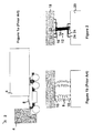
- FIG. 1a and 1b a known method of connecting supply lines in a tractor and trailer forming part of an articulated vehicle is shown.
- the articulated vehicle 2 comprises a tractor 4 and a trailer 6.
- a coiled cable known as a suzie 8 is used.
- a separate suzie is used to connect each of a plurality of supply lines as shown particularly in Figure 1b.
- Each suzie is connectable to a socket 10 in the tractor and trailer. Because the cables are coiled, changes in the distance between sockets in the tractor and the sockets in the trailer can be accommodated through stretching of the suzies 8.
- a connector according to the present invention is designated generally by the reference numeral 12.
- the connector comprises a connector support 14 for supporting connectors 16.
- the connectors are each adapted to connect a service line in a tractor 18 with a corresponding service line in a trailer 20.
- the tractor and trailer together form an articulated vehicle 40 and are thus detachable from one another.
- the tractor is pivotally connected to the trailer.
- the tractor comprises sockets 22, and the trailer comprises corresponding sockets 24.
- Each connector 16 is connectable to predetermined sockets 22, 24 in order to connect a supply line in the tractor with the appropriate supply line in the trailer.
- the number of connectors will depend upon the number of service lines present in the tractor and trailer, and in some cases there may be a single connector 16 only. However, in most cases there will be a plurality of connectors that will be carried by the connector support 14.
- the connector support in the illustrated embodiment comprises a first support portion 26 mounted on the tractor 18, and a second support portion 28 mounted on the trailer.
- the first support portion 26 is moveably mounted on the tractor by means of attachment 30, and the second support portion is moveably mounted on the trailer by means of an attachment 32.
- the attachments 30, 32 may take any convenient form, for example, a spring.
- each of the tractor and trailer comprises a mounting 34, 36 comprising a post 38.
- the attachments 30, 32 are shaped to fit around a respective post 36 in order to allow for easy attachment of the connector support 14 to the articulated vehicle 40.
- FIGS. 4a, 4b, 5 and 6 different embodiments of the attachment 30 are illustrated.
- the attachment is referred to by the reference numeral 30, although the embodiments shown in Figures 4a to 6 could also represent attachment 32.
- the attachment means 30 comprises biasing means in the form of an internal spring type support 400 which allows the support 26 to move from a substantially vertical position to a substantially horizontal position, and then to return to the vertical position once the forces causing the support to move towards the vertical position have ceased acting as shown in Figure 4b.
- the spring 400 is stretched. This causes tension in the spring which aids in the subsequent uprighting of the support 26.
- the attachment 30 comprises biasing means in the form of an external spring 500.
- a third embodiment of the attachment 30 comprising biasing means in the form of a pair of springs 600.
- the springs 600 are positioned so that when the support 26 moves from a substantially horizontal position towards a vertical position, one spring will become compressed and one will be in tension.
- tractor sockets 22 and trailer sockets 24 will vary according to the relative position of the tractor 18 and the trailer 20, as shown schematically in Figures 7a to 7d.
- the distance between the tractor sockets 22 and the trailer sockets 24 will be at a minimum, and the connector support 14 will be in the position shown in Figures 3 and 7a in which the first and second support portions 26, 28 extend in a substantially vertical direction.
- tractor sockets and trailer sockets lie in the same plane, then, when the support portions lie in the second position, they will lie in a plane close to or parallel to a plane in which at least one tractor socket and one trailer socket lies. In this embodiment, the plane in which the tractor sockets and trailer sockets lie substantially horizontal.
- the horizontal component of the length of the support portions 26, 28 will increase in response to the distance between tractor sockets 22 and trailer sockets 24 increasing.
- both of the first and second support portions 26, 28 are substantially vertical, and are therefore not visible in a plan view.
- one or both of the first and second support portions 26, 28 may comprise a flexible portion 70 as illustrated in Figures 8 and 9a to 9c. This means that, during extreme articulation of the tractor and the trailer 18, 20 one or both of the supports 26, 28 is able to bend around the front of the trailer whilst still maintaining support for the connectors 16.
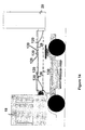
- Figure 10 shows schematically the first support portion 26 in a substantially vertical position.
- the support portion 26 carries a plurality of pipes and cables (in this case, five) in order to connect supply lines formed in the tractor 18 and trailer 20.
- the individual pipes and cables 42 are retained on the first support portion 26 by means of retainers 44 shown in more detail in Figures 12a, 12b and 13.
- the individual pipes and cables 42 are held together in a conduit 46 in order to reduce the number of potentially trailing pipes and cables extending between the first support portion 26 and the second support portion 28.
- the conduit also provides support to the cables and pipes along the length of the cables and pipes not supported by the first and second support portions 26, 28.
- the pipes and cables 42 are adapted to fit into plugs and sockets 48 formed in the tractor 18.
- plugs and sockets are routinely fitted to articulated vehicles and have previously been used with the known suzies mentioned hereinabove. This means that the present invention is able to make use of features which are usually standard in articulated vehicles.
- a connector according to the present invention is shown, connecting a gas supply line from the trailer 20 to the tractor 18.
- a gas supply line from the trailer 20 to the tractor 18.
- the connector 12 comprises a breakaway coupling 50 attached to a pipe 52.
- the pipe 52 is significantly shorter than pipes/cables connecting other service lines.
- the first support portion 28 would be pulled away from the tractor. Because the pipe connecting the gas supply lines to one another is shorter than the other connectors, the breakaway coupling will decouple before any other damage to the other connectors has occurred.
- the connector carrying the gas is significantly longer than the other connectors and therefore is the last connector that would become decoupled in the event of accidental trailer decoupling.
- the retainer 44 is shown in more detail.
- the retainer is shaped to receive each of the pipes/cables that are required to connector supply lines on the tractor and trailer.
- the retainer 44 comprises a first aperture 54 for receiving either the first or second support portions as appropriate. Once the retainer has been positioned on a support portion, connectors may be inserted into the open apertures 56 as appropriate.
- the retainer is sized and shaped so that it may move radially around the support portion to which it is attached thus allowing relative movement of the connectors 16 to the support portion 26 or 28.
- the retainer 120 comprises a breakable clip 122 defining a first aperture 124 for receiving either the first or the second support portions 24, 26 as appropriate.
- the retainer further comprises a support bracket 126 secured to the breakable clip 122, to which are attached the connectors 16.
- the retainer 120 serves to attach connectors 16 to the support portions 26, 28.
- a connector according to the present invention including a quick release device 58 for allowing removal of the connector according to the present invention from the trailer for stowage on the tractor when not in use.
- FIG 16 a further embodiment of the invention is shown. Parts of the embodiment of the invention shown in Figure 16 corresponding to parts in any of Figures 2 to 15 have been given corresponding reference numerals for ease of reference.
- the connector 12 illustrated in Figure 16 comprises a secondary biasing means 160 for biasing the connector support 14 in a first position, which in this example, is one in which the connector support 14 is in a substantially horizontal position.
- the secondary biasing means 160 may be used instead of or in conjunction with first and second biasing means described hereinabove with reference to Figures 2 to 15.
- the secondary biasing means is particularly useful when the connector support is supporting a large number of service lines or lines that are relatively heavy.
Landscapes
- Engineering & Computer Science (AREA)
- Transportation (AREA)
- Mechanical Engineering (AREA)
- Quick-Acting Or Multi-Walled Pipe Joints (AREA)
- Connector Housings Or Holding Contact Members (AREA)
- Piezo-Electric Or Mechanical Vibrators, Or Delay Or Filter Circuits (AREA)
- Earth Drilling (AREA)
- Structure Of Telephone Exchanges (AREA)
Abstract
a connector connectable to the first line connection means, and the second line connection means; and
a connector support (14) for supporting the connector (16), the connector support (14) being movable between a first position and a second position, wherein, in the first position the connector support extends in a direction substantially perpendicular to the connection plane.
Description
- This invention relates to a connector for connecting two or more service lines together, and particularly, but not exclusively, to a connector for connecting a service line on a tractor to a service line on a trailer, the tractor and trailer together forming an articulated vehicle.
- The term service line as used herein means a cable, pipe or other conduit for carrying and transmitting a commodity such as electricity, water, pressurised air or other gases etc.
- An articulated vehicle comprises an engine, or other power source for providing power to the vehicle, which engine is generally positioned on the tractor.
- It is necessary to ensure that the trailer is supplied with pressurised air, electricity and other services in order to operate brakes, lights and other fittings on the trailer.
- It can also be necessary to supply the tractor with, for example, compressed gas, if the engine is designed to run on compressed gas. Under such circumstances the compressed gas can be stored on the trailer, and it is necessary to have a service line running from the trailer to the tractor.
- A known articulated vehicle comprises, for example, two compressed air lines, one for a service brake, and one for an emergency brake, and three electricity lines for providing power to, for example, brakes, lights and other accessories fitted to, or positioned on the trailer.
- Because the tractor and trailer are disengageable it is not possible to have continuous service lines extending from the tractor to the trailer.
- It is known to form each of the trailer and the tractor with an appropriate number of service lines. Each service line formed in the tractor is connected with a corresponding service line in the trailer by means of a cable which is attachable to sockets in each of the tractor and trailer.
- The sockets attached to a particular service line may have predetermined dimensions that are different to the dimensions of other sockets attached to other service lines. This reduces the possibility that a service line in the tractor will be connected to the wrong line in the trailer, or vice versa.
- It is known for each service line to have a predetermined cable associated with it. In order to ensure that an appropriate cable is connected to each service line, each cable comprises a plug at each end of the cable, which plug is shaped to fit into a predetermined socket.
- The distance between the sockets on the tractor, and those on the trailer will vary depending on the angle of the tractor relative to the trailer. When the vehicle turns a corner, the distance between tractor sockets and trailer sockets will increase or decrease, due to relative movement of the tractor and trailer.
- In order to allow for these changes, the cables connecting the tractor sockets to the trailer sockets comprise coiled cables known as suzies.
- The coiled length of the cables is sufficient to connect service lines on the tractor and trailer when the distance between sockets is a minimum. When the distance increases, the cables uncoil as necessary to allow for the increased distance between sockets.
- A known problem with existing suzies is that, under certain circumstances, when an articulated vehicle makes a tight turn, suzies can become tangled or damaged when parts of the trailer contact them.
- Another problem is that the suzies can, through use, become overstretched, resulting in deformation of coils and further tangling problems.
- According to a first aspect of the present invention there is provided a device for connecting a first service line having a first line connection means to a second service line having a second line connection means, the first and second line connection means lying in a connection plane;
a connector connectable to the first line connection means, and the second line connection means; and
a connector support for supporting the connector, the connector support being movable between a first position and a second position, wherein, in the first position the connector support extends in a direction substantially perpendicular to the connection plane. - According to a second aspect of the present invention there is provided a method for connecting a first service line having a first line connection means to a second service line having a second line connection means, the first and second line connection means lying a connection plane, the method comprising the steps of:
- connecting a connector between the first line connection means and the second line connection means;
- attaching the connector to a connector support, the connector support being moveable between a first position and a second position, wherein, in the first position the connector extends in a direction substantially perpendicular to the connection plane.
- The connection plane is conveniently substantially horizontal, and the connector support extends substantially vertically in the first position.
- Advantageously, in the second position, the cable support extends in a direction extending parallel to, or at an acute angle to the connection plane.
- Preferably, the first service line connection means is located on a trailer, and the second service line connection means is located on a tractor, the trailer and the tractor being connectable to one another to form an articulated vehicle.
- It is known that the distance between the tractor and the trailer will vary depending on whether the vehicle is turning or has turned, and the extent of any turn being negotiated.
- When the distance between the tractor and trailer is at a minimum, the connector support is positioned in the first position and thus is substantially vertical.
- When the distance between a first line connection and a second line connection increases due to relative movement of the tractor and trailer, a force is applied to the connector, which force causes the connector support to move towards the second position. As the cable support moves from a substantially vertical position towards a horizontal position, the initially vertical length of the connector moves towards the horizontal, and thus increases the horizontal length of the connector.
- By means of the present invention, therefore, a connector having an appropriate length to connect a first line connection means to a second line connection means may be supported in such a way that when the distance between the first line connection means and the second line connection means is at a minimum, excess length in the connector is supported in a substantially vertical position by the connector support.
- This means, for example, that it is not necessary to use coiled connectors or suzies, and thus the disadvantages of such connectors as mentioned hereinabove are reduced or overcome.
- Advantageously, the connector support comprises a first support portion attachable to the tractor.
- Preferably the device further comprises a second support portion attachable to the trailer.
- The first and second support portions enable an elongate connector in the form of, for example, a cable or pipe to be supported along two portions of the connector.
- When the connector support comprises a first and second support portion, each of the first and second support portions will be positioned substantially perpendicular to the connection plane in the first position.
- Conveniently, the first support portion comprises first attachment means for moveably attaching the first support portion to the tractor, which attachment means comprises first biasing means for biasing the first support portion in the first position.
- Conveniently, the second support portion comprises second attachment means for moveably attaching the second support portion to the trailer, which second attachment means comprises second biasing means for biasing the second support portion in the first position.
- Each of the first and second support portions may be either permanently or removeably attached to the vehicle.
- In use, when an articulated vehicle negotiates a turn, the distance between the tractor and the trailer will vary. When the distance increases, force will be applied to the first and/or second support portions which will result in one or both of the first and second support portions moving from the first position towards the second position.
- This movement of the connector support means that an originally vertical length of the connector support moves towards a horizontal position in order to accommodate the increased length between the tractor and trailer.
- The first and second biasing means cause the connector support to return the first position once the turn has been completed.
- The first and second biasing means may take any convenient form and may comprise, for example, internal return springs, external return springs, or a hydraulic mechanism.
- Advantageously, the connector support comprises a retainer for retaining the connector on the connector support, the retainer comprising receiving means for receiving the connector, such that the connector is moveable relative to the connector support.
- Advantageously, the retainer allows the connector to move around the connector support in order to allow for articulation in the vehicle.
- Advantageously, the device according to the present invention is for connecting a plurality of first service lines to a plurality of second service lines, the connector support being adapted to support a plurality of connectors, each connector connecting one of the plurality of first service lines to a predetermined one of the plurality of second service lines.
- Advantageously, the receiving means is adapted to receive each of the plurality of connectors.
- Alternatively, the connector support comprises a retainer for retaining the connector on the connector support, the retainer comprising a retaining portion for retaining the connector on the connector support, the retainer comprising receiving means for receiving the connector such that the connector is moveable relative to the connector support.
- Preferably the connector support comprises a retainer for retaining the connector on the connector support, the retainer comprising a retaining portion for retaining the connector on the connector support, and a connecting portion for connecting the retainer to the connector, the connecting portion being releasably attached to the connector.
- Preferably, the retainer comprises a breakable clip fastened to the connector support.
- In an embodiment of the invention in which the device is for connecting a plurality of first service lines to a plurality of second service lines, the retainer is adapted to retain each of the plurality of connectors.
- The connector or connectors may take any convenient form appropriate for the service carried in the service line. For example, the connectors may comprise cables or pipes.
- Any number of first service lines may be connected by means of the present invention to any number of second service lines.
- Typically the service lines will comprise, for example, air, electricity and gas supplies.
- The service lines may also include lines for carrying a liquid that may be heated on a tractor unit of an articulated vehicle, and then transferred to the trailer of the articulated vehicle along one or more lines.
- The liquid may be heated on the tractor unit, and the transfer of the heated liquid may be assisted by means of pump.
- The device according to the present invention may further comprise secondary biasing means for biasing the connector support in the first position.
- The secondary biasing means may comprise any convenient mechanism such as a return spring mounted externally of the device, an elasticated bungee cord, a retractable lanyard or any other suitable device.
- When the connector support comprises a first connector portion and second connector portion, the device may comprise a first secondary biasing means and a second secondary biasing means.
- The secondary biasing means may be useful when the connector support is supporting a large number of service lines, or lines that are relatively heavy.
- The invention will now be further described by way of example only with reference to the accompanying drawings in which:
- Figures 1a and 1b illustrate known connectors for connecting supply lines in a tractor to supply lines in a trailer;
- Figure 2 is a schematic representation of a connector according to the present invention;
- Figure 3 is a schematic representation of the connector in Figure 2 showing the position of the connector in an articulated vehicle;
- Figures 4a, 4b, 5 and 6 illustrate embodiments of an attachment forming part of the connector according to the present invention;
- Figures 7a to 7d are schematic plan representations showing movement of the connector of Figure 2 in different relative positions of the tractor and trailer;
- Figures 8, 9a, 9b and 9c illustrate a support forming part of the present invention comprising a flexible portion;
- Figure 10 is a schematic representation of the connector of Figure 2 showing how individual pipes and cables are carried;
- Figure 11 is a schematic representation of the connector of Figure 2 incorporating a breakaway coupling attached to the gas supply;
- Figures 12a and 12b are schematic representations of a retainer for retaining various pipes and cables from the connector support forming part of the connector of Figure 2;
- Figures 13 and 14 illustrate a second embodiment of a retainer;
- Figure 15 is a schematic representation of the connector of Figure 2 showing a quick release device to allow removal of the device from the trailer; and
- Figure 16 is a schematic representation of a secondary biasing means forming part of an embodiment of the present invention.
- Referring to Figures 1a and 1b, a known method of connecting supply lines in a tractor and trailer forming part of an articulated vehicle is shown. The articulated
vehicle 2 comprises atractor 4 and atrailer 6. In order to connect a supply line in the trailer to a supply line in the tractor, a coiled cable known as asuzie 8 is used. A separate suzie is used to connect each of a plurality of supply lines as shown particularly in Figure 1b. Each suzie is connectable to asocket 10 in the tractor and trailer. Because the cables are coiled, changes in the distance between sockets in the tractor and the sockets in the trailer can be accommodated through stretching of thesuzies 8. - Turning now to Figures 2 to 16, embodiments of the present invention will now be described in detail by way of example only.
- Referring initially to Figures 2 and 3, a connector according to the present invention is designated generally by the
reference numeral 12. The connector comprises aconnector support 14 for supportingconnectors 16. The connectors are each adapted to connect a service line in atractor 18 with a corresponding service line in atrailer 20. The tractor and trailer together form an articulatedvehicle 40 and are thus detachable from one another. The tractor is pivotally connected to the trailer. - The tractor comprises
sockets 22, and the trailer comprises correspondingsockets 24. Eachconnector 16 is connectable topredetermined sockets - The number of connectors will depend upon the number of service lines present in the tractor and trailer, and in some cases there may be a
single connector 16 only. However, in most cases there will be a plurality of connectors that will be carried by theconnector support 14. - The connector support in the illustrated embodiment comprises a
first support portion 26 mounted on thetractor 18, and asecond support portion 28 mounted on the trailer. Thefirst support portion 26 is moveably mounted on the tractor by means ofattachment 30, and the second support portion is moveably mounted on the trailer by means of anattachment 32. Theattachments - Conveniently, each of the tractor and trailer comprises a mounting 34, 36 comprising a
post 38. Theattachments respective post 36 in order to allow for easy attachment of theconnector support 14 to the articulatedvehicle 40. - Referring to Figures 4a, 4b, 5 and 6 different embodiments of the
attachment 30 are illustrated. In each of Figures 4a to 6, the attachment is referred to by thereference numeral 30, although the embodiments shown in Figures 4a to 6 could also representattachment 32. - Referring to Figure 4a, it can be seen that the attachment means 30 comprises biasing means in the form of an internal
spring type support 400 which allows thesupport 26 to move from a substantially vertical position to a substantially horizontal position, and then to return to the vertical position once the forces causing the support to move towards the vertical position have ceased acting as shown in Figure 4b. As thesupport 26 moves towards the horizontal position, thespring 400 is stretched. This causes tension in the spring which aids in the subsequent uprighting of thesupport 26. - Turning now to Figure 5, a second embodiment of the
attachment 30 is shown. In Figure 5, theattachment 30 comprises biasing means in the form of anexternal spring 500. - In Figure 6 a third embodiment of the
attachment 30 is shown comprising biasing means in the form of a pair ofsprings 600. Thesprings 600 are positioned so that when thesupport 26 moves from a substantially horizontal position towards a vertical position, one spring will become compressed and one will be in tension. - The distance between
tractor sockets 22 andtrailer sockets 24 will vary according to the relative position of thetractor 18 and thetrailer 20, as shown schematically in Figures 7a to 7d. When the tractor and trailer are in the position shown in Figure 7a, the distance between thetractor sockets 22 and thetrailer sockets 24 will be at a minimum, and theconnector support 14 will be in the position shown in Figures 3 and 7a in which the first andsecond support portions - When the
tractor 18 moves relative to thetrailer 20, as shown in Figures 7b to 7d, the distance between thetractor sockets 22 and thetrailer sockets 24 will increase. This will result in a force being exerted on one or both of thesupport portions support portions - If not all of the tractor sockets and trailer sockets lie in the same plane, then, when the support portions lie in the second position, they will lie in a plane close to or parallel to a plane in which at least one tractor socket and one trailer socket lies. In this embodiment, the plane in which the tractor sockets and trailer sockets lie substantially horizontal.
- As one or both of the support portions moves from a vertical position towards the horizontal position, the horizontal component of the length of the
support portions tractor sockets 22 andtrailer sockets 24 increasing. - In Figure 7a, both of the first and
second support portions - In Figure 7b, movement of the
tractor 18 relative to thetrailer 20 results in thefirst support portion 26 moving away from the first position and towards the second position. - In Figure 7c, the further relative movement of the tractor and
trailer second support portion 28 from the first position towards the second position. - In Figure 7d, the further relative movement of the
tractor 18 and thetrailer 20 results in both the first support portion and the second support portion assuming a substantially horizontal position. - In certain embodiments of the present invention, one or both of the first and
second support portions flexible portion 70 as illustrated in Figures 8 and 9a to 9c. This means that, during extreme articulation of the tractor and thetrailer supports connectors 16. - Turning now to Figure 10, a
connector 12 according to the present invention is shown in more detail. Figure 10 shows schematically thefirst support portion 26 in a substantially vertical position. Thesupport portion 26 carries a plurality of pipes and cables (in this case, five) in order to connect supply lines formed in thetractor 18 andtrailer 20. The individual pipes and cables 42 are retained on thefirst support portion 26 by means ofretainers 44 shown in more detail in Figures 12a, 12b and 13. The individual pipes and cables 42 are held together in aconduit 46 in order to reduce the number of potentially trailing pipes and cables extending between thefirst support portion 26 and thesecond support portion 28. - The conduit also provides support to the cables and pipes along the length of the cables and pipes not supported by the first and
second support portions - The pipes and cables 42 are adapted to fit into plugs and sockets 48 formed in the
tractor 18. Such plugs and sockets are routinely fitted to articulated vehicles and have previously been used with the known suzies mentioned hereinabove. This means that the present invention is able to make use of features which are usually standard in articulated vehicles. - In Figure 11, a connector according to the present invention is shown, connecting a gas supply line from the
trailer 20 to thetractor 18. In vehicles in which the engine runs on gas or diesel and gas, it is desirable to house the gas reservoir on the trailer, and supply gas to the engine which is located in the tractor. - In order to prevent or reduce the chances of uncontrolled emission of gas in situations when, for example, the
tractor 18 is inadvertently disengaged from thetrailer 20 but theconnectors 16 have not been so disengaged, theconnector 12 comprises abreakaway coupling 50 attached to apipe 52. Thepipe 52 is significantly shorter than pipes/cables connecting other service lines. - In the event of accidental trailer decoupling, the
first support portion 28 would be pulled away from the tractor. Because the pipe connecting the gas supply lines to one another is shorter than the other connectors, the breakaway coupling will decouple before any other damage to the other connectors has occurred. - In an alternative embodiment, the connector carrying the gas is significantly longer than the other connectors and therefore is the last connector that would become decoupled in the event of accidental trailer decoupling.
- Referring now to Figure 12a and 12b, a
retainer 44 is shown in more detail. The retainer is shaped to receive each of the pipes/cables that are required to connector supply lines on the tractor and trailer. - The
retainer 44 comprises afirst aperture 54 for receiving either the first or second support portions as appropriate. Once the retainer has been positioned on a support portion, connectors may be inserted into theopen apertures 56 as appropriate. The retainer is sized and shaped so that it may move radially around the support portion to which it is attached thus allowing relative movement of theconnectors 16 to thesupport portion - Referring to Figures 13 and 14, a second embodiment of a retainer is illustrated and is designated generally by the
reference numeral 120. Theretainer 120 comprises abreakable clip 122 defining afirst aperture 124 for receiving either the first or thesecond support portions support bracket 126 secured to thebreakable clip 122, to which are attached theconnectors 16. - Turning now to Figure 14, an articulated vehicle incorporating the retaining means 120 is shown. The
retainer 120 serves to attachconnectors 16 to thesupport portions - In the event of a separation of the
trailer 20 from thetractor 18 without prior disconnection of theconnectors 16, thesupport portions breakable clips 122 forming theretainers 120 will then fail, allowing the service lines to be pulled into a substantially horizontal position indicated by the dottedline 130. - In an embodiment where there is a breakaway coupling attaching a gas line to the trailer, this results in the gas line being presented to the breakaway coupling in a substantially horizontal position. This reduces the chance of the breakaway coupling malfunctioning, and increases the chances of the coupling failing in the designed manner.
- Referring to Figure 15, a connector according to the present invention is shown including a
quick release device 58 for allowing removal of the connector according to the present invention from the trailer for stowage on the tractor when not in use. - Referring to Figure 16, a further embodiment of the invention is shown. Parts of the embodiment of the invention shown in Figure 16 corresponding to parts in any of Figures 2 to 15 have been given corresponding reference numerals for ease of reference.
- The
connector 12 illustrated in Figure 16 comprises a secondary biasing means 160 for biasing theconnector support 14 in a first position, which in this example, is one in which theconnector support 14 is in a substantially horizontal position. The secondary biasing means 160 may be used instead of or in conjunction with first and second biasing means described hereinabove with reference to Figures 2 to 15. The secondary biasing means is particularly useful when the connector support is supporting a large number of service lines or lines that are relatively heavy.
Claims (22)
- A device for connecting a first service line having a first line connection means to a second service line having a second line connection means, the first and second line connection means lying in a connection plane;
a connector connectable to the first line connection means, and the second line connection means; and
a connector support for supporting the connector, the connector support being movable between a first position and a second position, wherein, in the first position the connector support extends in a direction substantially perpendicular to the connection plane. - A device according to Claim 1, wherein the connection plane is substantially horizontal, and the connector support extends substantially vertically in the first position.
- A device according to any one of the preceding claims wherein the second position, the connector support extends in a direction extending parallel to, or at an acute angle to the connection plane.
- A device according to Claim 1 or Claim 2, wherein the first service line connection means is located on a trailer, and the second service line connection means is located on a tractor, the trailer and the tractor being connectable to one another to form an articulated vehicle.
- A device according to Claim 4, wherein the connector support comprises a first support portion attachable to the tractor.
- A device according to Claim 4 or Claim 5, wherein the connector support comprises a second support portion attachable to the trailer.
- A device according to any one of Claims 4, 5 and 6, wherein the first support portion comprises first attachment means for moveably attaching the first support portion to the tractor, which attachment means comprises first biasing means for biasing the first support portion in the first position.
- A device according to any of Claims 4 to 7, wherein the second support portion comprises second attachment means for moveably attaching the second support portion to the trailer, which second attachment means comprises second biasing means for biasing the second support portion in the first position.
- A device according to Claim 7 or Claim 8, wherein the first support portion is permanently attached to the tractor.
- A device according to Claim 8 or Claim 9 when dependent upon Claim 8, wherein the second support portion is permanently attached to the trailer.
- A device according to any one of the preceding claims wherein the connector support comprises a retainer for retaining the connector on the connector support, the retainer comprising receiving means for receiving the connector, such that the connector is moveable relative to the connector support.
- A device according to any one of Claims 1 to 10, wherein the connector support comprises a retainer for retaining the connector on the connector support, the retainer comprising a retaining portion for retaining the connector on the connector support, and a connecting portion for connecting the retainer to the connector, the connecting portion being releasably attached to the connector.
- A device according to Claim 12, wherein the connecting portion of the retainer comprises a breakable clip fastened to the connector support.
- A device according to any one of the preceding claims, for connecting a plurality of first service lines to a plurality of second service lines, the connector support being adapted to support a plurality of connectors, each connector connecting one of the plurality of first service lines to a predetermined one of the plurality of second lines, one or more of the first and second lines lying in a connection plane.
- A device according to Claim 14 when dependent on Claim 11, or any claim dependent thereon, wherein the receiving means is for receiving each of the plurality of connectors.
- A device according to Claim 14 and dependent upon Claim 12 or Claim 13 or any claim dependent thereon, wherein the retaining portion is adapted to retain each of the plurality of connectors.
- A device according to any one of the preceding claims wherein the connector support comprises a flexible portion.
- A device according to any one of the preceding claims further comprising secondary biasing means for biasing the connector support in the first position.
- A method for connecting a first service line having a first line connection means to a second service line having a second line connection means, the first and second line connection means lying a connection plane, the method comprising the steps of:connecting a connector between the first line connection means and the second line connection means;attaching the connector to a connector support, the connector support being moveable between a first position and a second position, wherein, in the first position the connector extends in a direction substantially perpendicular to the connection plane.
- An articulated vehicle comprising a device according to any one of Claims 1 to 18.
- A device substantially as hereinbefore described with reference to the accompanying drawings.
- A method substantially as hereinbefore described with reference to the accompanying drawings.
Applications Claiming Priority (1)
| Application Number | Priority Date | Filing Date | Title |
|---|---|---|---|
| GBGB0415795.4A GB0415795D0 (en) | 2004-07-15 | 2004-07-15 | A connector |
Publications (2)
| Publication Number | Publication Date |
|---|---|
| EP1616728A1 true EP1616728A1 (en) | 2006-01-18 |
| EP1616728B1 EP1616728B1 (en) | 2008-03-12 |
Family
ID=32893581
Family Applications (1)
| Application Number | Title | Priority Date | Filing Date |
|---|---|---|---|
| EP05254429A Not-in-force EP1616728B1 (en) | 2004-07-15 | 2005-07-15 | A connector |
Country Status (5)
| Country | Link |
|---|---|
| EP (1) | EP1616728B1 (en) |
| AT (1) | ATE388834T1 (en) |
| DE (1) | DE602005005248T2 (en) |
| ES (1) | ES2308400T3 (en) |
| GB (1) | GB0415795D0 (en) |
Citations (6)
| Publication number | Priority date | Publication date | Assignee | Title |
|---|---|---|---|---|
| US2170557A (en) * | 1938-03-24 | 1939-08-22 | Packless Metal Products Corp | Support for flexible hose |
| US2733033A (en) * | 1956-01-31 | Ctatbs patpntxr | ||
| DE1793338U (en) * | 1959-01-30 | 1959-08-13 | Bbc Brown Boveri & Cie | ELECTRIC DOUBLE COUPLING BETWEEN VEHICLES, IN PARTICULAR MOVING DOUBLE HIGH VOLTAGE ROOF COUPLING. |
| US2978217A (en) * | 1958-11-19 | 1961-04-04 | Ralph R Gunderson | Yielding support for vehicle hose lines |
| US6095181A (en) * | 1999-09-09 | 2000-08-01 | Caterpillar S.A.R.L. | Articulated machine overhitch hose support |
| GB2365397A (en) * | 2000-06-30 | 2002-02-20 | Safeway Stores | Trailer mounting for service lines |
-
2004
- 2004-07-15 GB GBGB0415795.4A patent/GB0415795D0/en not_active Ceased
-
2005
- 2005-07-15 ES ES05254429T patent/ES2308400T3/en active Active
- 2005-07-15 AT AT05254429T patent/ATE388834T1/en not_active IP Right Cessation
- 2005-07-15 EP EP05254429A patent/EP1616728B1/en not_active Not-in-force
- 2005-07-15 DE DE602005005248T patent/DE602005005248T2/en active Active
Patent Citations (6)
| Publication number | Priority date | Publication date | Assignee | Title |
|---|---|---|---|---|
| US2733033A (en) * | 1956-01-31 | Ctatbs patpntxr | ||
| US2170557A (en) * | 1938-03-24 | 1939-08-22 | Packless Metal Products Corp | Support for flexible hose |
| US2978217A (en) * | 1958-11-19 | 1961-04-04 | Ralph R Gunderson | Yielding support for vehicle hose lines |
| DE1793338U (en) * | 1959-01-30 | 1959-08-13 | Bbc Brown Boveri & Cie | ELECTRIC DOUBLE COUPLING BETWEEN VEHICLES, IN PARTICULAR MOVING DOUBLE HIGH VOLTAGE ROOF COUPLING. |
| US6095181A (en) * | 1999-09-09 | 2000-08-01 | Caterpillar S.A.R.L. | Articulated machine overhitch hose support |
| GB2365397A (en) * | 2000-06-30 | 2002-02-20 | Safeway Stores | Trailer mounting for service lines |
Also Published As
| Publication number | Publication date |
|---|---|
| GB0415795D0 (en) | 2004-08-18 |
| EP1616728B1 (en) | 2008-03-12 |
| ES2308400T3 (en) | 2008-12-01 |
| ATE388834T1 (en) | 2008-03-15 |
| DE602005005248T2 (en) | 2009-04-30 |
| DE602005005248D1 (en) | 2008-04-24 |
Similar Documents
| Publication | Publication Date | Title |
|---|---|---|
| US7086659B2 (en) | Trailer line routing | |
| US8296914B2 (en) | Device for connecting the end of a flexible liquid supply pipe to a fixed tubing such as the manifold on a ship | |
| CA2422121A1 (en) | Assembly with articulated arm for loading and unloading products, in particular fluid products | |
| BR102016029327A2 (en) | ASSEMBLY AND CONNECTION OF WORK VEHICLE MULTIACHLERS, AND, WORK VEHICLE | |
| JPH0565986A (en) | Adapter for connecting hose | |
| US20040011918A1 (en) | Aviation ground power unit connection system and method incorporating same | |
| US20030038102A1 (en) | Mounting block assembly for electrical interconnection between rail cars | |
| CN103930340B (en) | Tractor and trailer combines | |
| BRPI0519573B1 (en) | system for connecting power lines | |
| US20130221166A1 (en) | Rail Car Intercar Cable Arrangement, Rail Car Intercar Cable, and Hanger Arrangement Therefor | |
| US20060103111A1 (en) | Trailer hitching apparatus | |
| WO2009082325A1 (en) | A clip device, a system for attachment of conduits comprising said clip device as well as a heavy vehicle comprising said clip device and/or system | |
| EP1616728A1 (en) | A connector | |
| US5069631A (en) | Electrical breakaway conductor | |
| GB2209507A (en) | Towing coupling for service lines | |
| EP1149435B1 (en) | Snatch disconnection lanyard | |
| CN109689416B (en) | Device for mounting evaporation pipe of liquefied gas fuel system to vehicle | |
| CN102858594A (en) | Exterior mirror unit, mirror support, method for assembly of an exterior mirror unit | |
| EP1867884A1 (en) | Improvements relating to vehicle steering | |
| CN201320941Y (en) | Correcting device for connection of vehicle and auxiliary device | |
| GB2365397A (en) | Trailer mounting for service lines | |
| EP2580509A1 (en) | Line retainer device | |
| JP3177794U (en) | Trailer tractor connection structure | |
| CN217686865U (en) | Rocket connector active pulling-out device | |
| US11796104B2 (en) | Quick connector structure for automobiles |
Legal Events
| Date | Code | Title | Description |
|---|---|---|---|
| PUAI | Public reference made under article 153(3) epc to a published international application that has entered the european phase |
Free format text: ORIGINAL CODE: 0009012 |
|
| AK | Designated contracting states |
Kind code of ref document: A1 Designated state(s): AT BE BG CH CY CZ DE DK EE ES FI FR GB GR HU IE IS IT LI LT LU LV MC NL PL PT RO SE SI SK TR |
|
| AX | Request for extension of the european patent |
Extension state: AL BA HR MK YU |
|
| 17P | Request for examination filed |
Effective date: 20060717 |
|
| AKX | Designation fees paid |
Designated state(s): AT BE BG CH CY CZ DE DK EE ES FI FR GB GR HU IE IS IT LI LT LU LV MC NL PL PT RO SE SI SK TR |
|
| 17Q | First examination report despatched |
Effective date: 20060911 |
|
| GRAP | Despatch of communication of intention to grant a patent |
Free format text: ORIGINAL CODE: EPIDOSNIGR1 |
|
| GRAS | Grant fee paid |
Free format text: ORIGINAL CODE: EPIDOSNIGR3 |
|
| GRAA | (expected) grant |
Free format text: ORIGINAL CODE: 0009210 |
|
| AK | Designated contracting states |
Kind code of ref document: B1 Designated state(s): AT BE BG CH CY CZ DE DK EE ES FI FR GB GR HU IE IS IT LI LT LU LV MC NL PL PT RO SE SI SK TR |
|
| REG | Reference to a national code |
Ref country code: GB Ref legal event code: FG4D |
|
| REG | Reference to a national code |
Ref country code: CH Ref legal event code: EP |
|
| REG | Reference to a national code |
Ref country code: IE Ref legal event code: FG4D |
|
| REF | Corresponds to: |
Ref document number: 602005005248 Country of ref document: DE Date of ref document: 20080424 Kind code of ref document: P |
|
| REG | Reference to a national code |
Ref country code: SE Ref legal event code: TRGR |
|
| PG25 | Lapsed in a contracting state [announced via postgrant information from national office to epo] |
Ref country code: FI Free format text: LAPSE BECAUSE OF FAILURE TO SUBMIT A TRANSLATION OF THE DESCRIPTION OR TO PAY THE FEE WITHIN THE PRESCRIBED TIME-LIMIT Effective date: 20080312 |
|
| PG25 | Lapsed in a contracting state [announced via postgrant information from national office to epo] |
Ref country code: AT Free format text: LAPSE BECAUSE OF FAILURE TO SUBMIT A TRANSLATION OF THE DESCRIPTION OR TO PAY THE FEE WITHIN THE PRESCRIBED TIME-LIMIT Effective date: 20080312 |
|
| PG25 | Lapsed in a contracting state [announced via postgrant information from national office to epo] |
Ref country code: LV Free format text: LAPSE BECAUSE OF FAILURE TO SUBMIT A TRANSLATION OF THE DESCRIPTION OR TO PAY THE FEE WITHIN THE PRESCRIBED TIME-LIMIT Effective date: 20080312 Ref country code: PL Free format text: LAPSE BECAUSE OF FAILURE TO SUBMIT A TRANSLATION OF THE DESCRIPTION OR TO PAY THE FEE WITHIN THE PRESCRIBED TIME-LIMIT Effective date: 20080312 Ref country code: SI Free format text: LAPSE BECAUSE OF FAILURE TO SUBMIT A TRANSLATION OF THE DESCRIPTION OR TO PAY THE FEE WITHIN THE PRESCRIBED TIME-LIMIT Effective date: 20080312 Ref country code: BE Free format text: LAPSE BECAUSE OF FAILURE TO SUBMIT A TRANSLATION OF THE DESCRIPTION OR TO PAY THE FEE WITHIN THE PRESCRIBED TIME-LIMIT Effective date: 20080312 |
|
| PG25 | Lapsed in a contracting state [announced via postgrant information from national office to epo] |
Ref country code: CZ Free format text: LAPSE BECAUSE OF FAILURE TO SUBMIT A TRANSLATION OF THE DESCRIPTION OR TO PAY THE FEE WITHIN THE PRESCRIBED TIME-LIMIT Effective date: 20080312 Ref country code: PT Free format text: LAPSE BECAUSE OF FAILURE TO SUBMIT A TRANSLATION OF THE DESCRIPTION OR TO PAY THE FEE WITHIN THE PRESCRIBED TIME-LIMIT Effective date: 20080818 Ref country code: SK Free format text: LAPSE BECAUSE OF FAILURE TO SUBMIT A TRANSLATION OF THE DESCRIPTION OR TO PAY THE FEE WITHIN THE PRESCRIBED TIME-LIMIT Effective date: 20080312 |
|
| REG | Reference to a national code |
Ref country code: CH Ref legal event code: NV Representative=s name: KIRKER & CIE S.A. |
|
| PG25 | Lapsed in a contracting state [announced via postgrant information from national office to epo] |
Ref country code: RO Free format text: LAPSE BECAUSE OF FAILURE TO SUBMIT A TRANSLATION OF THE DESCRIPTION OR TO PAY THE FEE WITHIN THE PRESCRIBED TIME-LIMIT Effective date: 20080312 |
|
| REG | Reference to a national code |
Ref country code: ES Ref legal event code: FG2A Ref document number: 2308400 Country of ref document: ES Kind code of ref document: T3 |
|
| ET | Fr: translation filed | ||
| PG25 | Lapsed in a contracting state [announced via postgrant information from national office to epo] |
Ref country code: IS Free format text: LAPSE BECAUSE OF FAILURE TO SUBMIT A TRANSLATION OF THE DESCRIPTION OR TO PAY THE FEE WITHIN THE PRESCRIBED TIME-LIMIT Effective date: 20080712 |
|
| PLBE | No opposition filed within time limit |
Free format text: ORIGINAL CODE: 0009261 |
|
| STAA | Information on the status of an ep patent application or granted ep patent |
Free format text: STATUS: NO OPPOSITION FILED WITHIN TIME LIMIT |
|
| PG25 | Lapsed in a contracting state [announced via postgrant information from national office to epo] |
Ref country code: DK Free format text: LAPSE BECAUSE OF FAILURE TO SUBMIT A TRANSLATION OF THE DESCRIPTION OR TO PAY THE FEE WITHIN THE PRESCRIBED TIME-LIMIT Effective date: 20080312 |
|
| 26N | No opposition filed |
Effective date: 20081215 |
|
| PG25 | Lapsed in a contracting state [announced via postgrant information from national office to epo] |
Ref country code: MC Free format text: LAPSE BECAUSE OF NON-PAYMENT OF DUE FEES Effective date: 20080731 |
|
| PG25 | Lapsed in a contracting state [announced via postgrant information from national office to epo] |
Ref country code: BG Free format text: LAPSE BECAUSE OF FAILURE TO SUBMIT A TRANSLATION OF THE DESCRIPTION OR TO PAY THE FEE WITHIN THE PRESCRIBED TIME-LIMIT Effective date: 20080612 Ref country code: EE Free format text: LAPSE BECAUSE OF FAILURE TO SUBMIT A TRANSLATION OF THE DESCRIPTION OR TO PAY THE FEE WITHIN THE PRESCRIBED TIME-LIMIT Effective date: 20080312 |
|
| PG25 | Lapsed in a contracting state [announced via postgrant information from national office to epo] |
Ref country code: IE Free format text: LAPSE BECAUSE OF NON-PAYMENT OF DUE FEES Effective date: 20080715 |
|
| PG25 | Lapsed in a contracting state [announced via postgrant information from national office to epo] |
Ref country code: CY Free format text: LAPSE BECAUSE OF FAILURE TO SUBMIT A TRANSLATION OF THE DESCRIPTION OR TO PAY THE FEE WITHIN THE PRESCRIBED TIME-LIMIT Effective date: 20080312 |
|
| PG25 | Lapsed in a contracting state [announced via postgrant information from national office to epo] |
Ref country code: HU Free format text: LAPSE BECAUSE OF FAILURE TO SUBMIT A TRANSLATION OF THE DESCRIPTION OR TO PAY THE FEE WITHIN THE PRESCRIBED TIME-LIMIT Effective date: 20080913 Ref country code: LU Free format text: LAPSE BECAUSE OF NON-PAYMENT OF DUE FEES Effective date: 20080715 |
|
| PG25 | Lapsed in a contracting state [announced via postgrant information from national office to epo] |
Ref country code: TR Free format text: LAPSE BECAUSE OF FAILURE TO SUBMIT A TRANSLATION OF THE DESCRIPTION OR TO PAY THE FEE WITHIN THE PRESCRIBED TIME-LIMIT Effective date: 20080312 |
|
| PG25 | Lapsed in a contracting state [announced via postgrant information from national office to epo] |
Ref country code: GR Free format text: LAPSE BECAUSE OF FAILURE TO SUBMIT A TRANSLATION OF THE DESCRIPTION OR TO PAY THE FEE WITHIN THE PRESCRIBED TIME-LIMIT Effective date: 20080613 |
|
| PG25 | Lapsed in a contracting state [announced via postgrant information from national office to epo] |
Ref country code: IT Free format text: LAPSE BECAUSE OF NON-PAYMENT OF DUE FEES Effective date: 20100715 |
|
| PGRI | Patent reinstated in contracting state [announced from national office to epo] |
Ref country code: IT Effective date: 20110616 |
|
| PGFP | Annual fee paid to national office [announced via postgrant information from national office to epo] |
Ref country code: LT Payment date: 20110824 Year of fee payment: 7 Ref country code: CH Payment date: 20110826 Year of fee payment: 7 |
|
| REG | Reference to a national code |
Ref country code: LT Ref legal event code: MM4D Effective date: 20120715 |
|
| REG | Reference to a national code |
Ref country code: CH Ref legal event code: PL |
|
| PG25 | Lapsed in a contracting state [announced via postgrant information from national office to epo] |
Ref country code: CH Free format text: LAPSE BECAUSE OF NON-PAYMENT OF DUE FEES Effective date: 20120731 Ref country code: LT Free format text: LAPSE BECAUSE OF NON-PAYMENT OF DUE FEES Effective date: 20120715 Ref country code: LI Free format text: LAPSE BECAUSE OF NON-PAYMENT OF DUE FEES Effective date: 20120731 |
|
| PGFP | Annual fee paid to national office [announced via postgrant information from national office to epo] |
Ref country code: DE Payment date: 20140917 Year of fee payment: 10 |
|
| PGFP | Annual fee paid to national office [announced via postgrant information from national office to epo] |
Ref country code: ES Payment date: 20140929 Year of fee payment: 10 Ref country code: GB Payment date: 20140917 Year of fee payment: 10 Ref country code: SE Payment date: 20140926 Year of fee payment: 10 |
|
| PGFP | Annual fee paid to national office [announced via postgrant information from national office to epo] |
Ref country code: IT Payment date: 20140926 Year of fee payment: 10 |
|
| PGFP | Annual fee paid to national office [announced via postgrant information from national office to epo] |
Ref country code: FR Payment date: 20140923 Year of fee payment: 10 |
|
| PGFP | Annual fee paid to national office [announced via postgrant information from national office to epo] |
Ref country code: NL Payment date: 20140926 Year of fee payment: 10 |
|
| REG | Reference to a national code |
Ref country code: DE Ref legal event code: R119 Ref document number: 602005005248 Country of ref document: DE |
|
| REG | Reference to a national code |
Ref country code: SE Ref legal event code: EUG |
|
| GBPC | Gb: european patent ceased through non-payment of renewal fee |
Effective date: 20150715 |
|
| REG | Reference to a national code |
Ref country code: NL Ref legal event code: MM Effective date: 20150801 |
|
| PG25 | Lapsed in a contracting state [announced via postgrant information from national office to epo] |
Ref country code: DE Free format text: LAPSE BECAUSE OF NON-PAYMENT OF DUE FEES Effective date: 20160202 Ref country code: IT Free format text: LAPSE BECAUSE OF NON-PAYMENT OF DUE FEES Effective date: 20150715 Ref country code: GB Free format text: LAPSE BECAUSE OF NON-PAYMENT OF DUE FEES Effective date: 20150715 |
|
| REG | Reference to a national code |
Ref country code: FR Ref legal event code: ST Effective date: 20160331 |
|
| PG25 | Lapsed in a contracting state [announced via postgrant information from national office to epo] |
Ref country code: SE Free format text: LAPSE BECAUSE OF NON-PAYMENT OF DUE FEES Effective date: 20150716 Ref country code: FR Free format text: LAPSE BECAUSE OF NON-PAYMENT OF DUE FEES Effective date: 20150731 Ref country code: NL Free format text: LAPSE BECAUSE OF NON-PAYMENT OF DUE FEES Effective date: 20150801 |
|
| REG | Reference to a national code |
Ref country code: ES Ref legal event code: FD2A Effective date: 20160826 |
|
| PG25 | Lapsed in a contracting state [announced via postgrant information from national office to epo] |
Ref country code: ES Free format text: LAPSE BECAUSE OF NON-PAYMENT OF DUE FEES Effective date: 20150716 |