EP1615787B1 - Method and system for aligning a stationary vehicle with an artificial horizon - Google Patents
Method and system for aligning a stationary vehicle with an artificial horizon Download PDFInfo
- Publication number
- EP1615787B1 EP1615787B1 EP04775892A EP04775892A EP1615787B1 EP 1615787 B1 EP1615787 B1 EP 1615787B1 EP 04775892 A EP04775892 A EP 04775892A EP 04775892 A EP04775892 A EP 04775892A EP 1615787 B1 EP1615787 B1 EP 1615787B1
- Authority
- EP
- European Patent Office
- Prior art keywords
- vehicle
- chassis
- alignment
- signal
- control unit
- Prior art date
- Legal status (The legal status is an assumption and is not a legal conclusion. Google has not performed a legal analysis and makes no representation as to the accuracy of the status listed.)
- Expired - Lifetime
Links
- 238000000034 method Methods 0.000 title claims abstract description 43
- 239000012530 fluid Substances 0.000 claims abstract description 113
- 239000000725 suspension Substances 0.000 claims abstract description 78
- 238000004891 communication Methods 0.000 claims abstract description 24
- FGUUSXIOTUKUDN-IBGZPJMESA-N C1(=CC=CC=C1)N1C2=C(NC([C@H](C1)NC=1OC(=NN=1)C1=CC=CC=C1)=O)C=CC=C2 Chemical compound C1(=CC=CC=C1)N1C2=C(NC([C@H](C1)NC=1OC(=NN=1)C1=CC=CC=C1)=O)C=CC=C2 FGUUSXIOTUKUDN-IBGZPJMESA-N 0.000 claims description 5
- 238000001514 detection method Methods 0.000 description 8
- 238000010586 diagram Methods 0.000 description 8
- 230000004048 modification Effects 0.000 description 6
- 238000012986 modification Methods 0.000 description 6
- 230000001276 controlling effect Effects 0.000 description 4
- 230000033001 locomotion Effects 0.000 description 4
- 230000008901 benefit Effects 0.000 description 3
- 230000004075 alteration Effects 0.000 description 2
- 239000010426 asphalt Substances 0.000 description 2
- 238000010276 construction Methods 0.000 description 2
- 230000001419 dependent effect Effects 0.000 description 2
- 230000001105 regulatory effect Effects 0.000 description 2
- 230000005355 Hall effect Effects 0.000 description 1
- 230000003213 activating effect Effects 0.000 description 1
- 230000005540 biological transmission Effects 0.000 description 1
- 230000000881 depressing effect Effects 0.000 description 1
- 230000000994 depressogenic effect Effects 0.000 description 1
- 230000009977 dual effect Effects 0.000 description 1
- 230000000694 effects Effects 0.000 description 1
- 230000000977 initiatory effect Effects 0.000 description 1
- 239000000463 material Substances 0.000 description 1
- QSHDDOUJBYECFT-UHFFFAOYSA-N mercury Chemical compound [Hg] QSHDDOUJBYECFT-UHFFFAOYSA-N 0.000 description 1
- 229910052753 mercury Inorganic materials 0.000 description 1
- 230000004044 response Effects 0.000 description 1
- 230000003584 silencer Effects 0.000 description 1
Images





Classifications
-
- B—PERFORMING OPERATIONS; TRANSPORTING
- B60—VEHICLES IN GENERAL
- B60G—VEHICLE SUSPENSION ARRANGEMENTS
- B60G17/00—Resilient suspensions having means for adjusting the spring or vibration-damper characteristics, for regulating the distance between a supporting surface and a sprung part of vehicle or for locking suspension during use to meet varying vehicular or surface conditions, e.g. due to speed or load
- B60G17/015—Resilient suspensions having means for adjusting the spring or vibration-damper characteristics, for regulating the distance between a supporting surface and a sprung part of vehicle or for locking suspension during use to meet varying vehicular or surface conditions, e.g. due to speed or load the regulating means comprising electric or electronic elements
- B60G17/0152—Resilient suspensions having means for adjusting the spring or vibration-damper characteristics, for regulating the distance between a supporting surface and a sprung part of vehicle or for locking suspension during use to meet varying vehicular or surface conditions, e.g. due to speed or load the regulating means comprising electric or electronic elements characterised by the action on a particular type of suspension unit
- B60G17/0155—Resilient suspensions having means for adjusting the spring or vibration-damper characteristics, for regulating the distance between a supporting surface and a sprung part of vehicle or for locking suspension during use to meet varying vehicular or surface conditions, e.g. due to speed or load the regulating means comprising electric or electronic elements characterised by the action on a particular type of suspension unit pneumatic unit
-
- B—PERFORMING OPERATIONS; TRANSPORTING
- B60—VEHICLES IN GENERAL
- B60G—VEHICLE SUSPENSION ARRANGEMENTS
- B60G17/00—Resilient suspensions having means for adjusting the spring or vibration-damper characteristics, for regulating the distance between a supporting surface and a sprung part of vehicle or for locking suspension during use to meet varying vehicular or surface conditions, e.g. due to speed or load
- B60G17/015—Resilient suspensions having means for adjusting the spring or vibration-damper characteristics, for regulating the distance between a supporting surface and a sprung part of vehicle or for locking suspension during use to meet varying vehicular or surface conditions, e.g. due to speed or load the regulating means comprising electric or electronic elements
- B60G17/017—Resilient suspensions having means for adjusting the spring or vibration-damper characteristics, for regulating the distance between a supporting surface and a sprung part of vehicle or for locking suspension during use to meet varying vehicular or surface conditions, e.g. due to speed or load the regulating means comprising electric or electronic elements characterised by their use when the vehicle is stationary, e.g. during loading, engine start-up or switch-off
-
- B—PERFORMING OPERATIONS; TRANSPORTING
- B60—VEHICLES IN GENERAL
- B60G—VEHICLE SUSPENSION ARRANGEMENTS
- B60G17/00—Resilient suspensions having means for adjusting the spring or vibration-damper characteristics, for regulating the distance between a supporting surface and a sprung part of vehicle or for locking suspension during use to meet varying vehicular or surface conditions, e.g. due to speed or load
- B60G17/015—Resilient suspensions having means for adjusting the spring or vibration-damper characteristics, for regulating the distance between a supporting surface and a sprung part of vehicle or for locking suspension during use to meet varying vehicular or surface conditions, e.g. due to speed or load the regulating means comprising electric or electronic elements
- B60G17/019—Resilient suspensions having means for adjusting the spring or vibration-damper characteristics, for regulating the distance between a supporting surface and a sprung part of vehicle or for locking suspension during use to meet varying vehicular or surface conditions, e.g. due to speed or load the regulating means comprising electric or electronic elements characterised by the type of sensor or the arrangement thereof
- B60G17/01908—Acceleration or inclination sensors
-
- B—PERFORMING OPERATIONS; TRANSPORTING
- B60—VEHICLES IN GENERAL
- B60G—VEHICLE SUSPENSION ARRANGEMENTS
- B60G2400/00—Indexing codes relating to detected, measured or calculated conditions or factors
- B60G2400/05—Attitude
- B60G2400/051—Angle
-
- B—PERFORMING OPERATIONS; TRANSPORTING
- B60—VEHICLES IN GENERAL
- B60G—VEHICLE SUSPENSION ARRANGEMENTS
- B60G2400/00—Indexing codes relating to detected, measured or calculated conditions or factors
- B60G2400/10—Acceleration; Deceleration
-
- B—PERFORMING OPERATIONS; TRANSPORTING
- B60—VEHICLES IN GENERAL
- B60G—VEHICLE SUSPENSION ARRANGEMENTS
- B60G2400/00—Indexing codes relating to detected, measured or calculated conditions or factors
- B60G2400/20—Speed
- B60G2400/204—Vehicle speed
-
- B—PERFORMING OPERATIONS; TRANSPORTING
- B60—VEHICLES IN GENERAL
- B60G—VEHICLE SUSPENSION ARRANGEMENTS
- B60G2400/00—Indexing codes relating to detected, measured or calculated conditions or factors
- B60G2400/25—Stroke; Height; Displacement
- B60G2400/252—Stroke; Height; Displacement vertical
-
- B—PERFORMING OPERATIONS; TRANSPORTING
- B60—VEHICLES IN GENERAL
- B60G—VEHICLE SUSPENSION ARRANGEMENTS
- B60G2500/00—Indexing codes relating to the regulated action or device
- B60G2500/20—Spring action or springs
- B60G2500/201—Air spring system type
-
- B—PERFORMING OPERATIONS; TRANSPORTING
- B60—VEHICLES IN GENERAL
- B60G—VEHICLE SUSPENSION ARRANGEMENTS
- B60G2500/00—Indexing codes relating to the regulated action or device
- B60G2500/20—Spring action or springs
- B60G2500/204—Pressure regulating valves for air-springs
-
- B—PERFORMING OPERATIONS; TRANSPORTING
- B60—VEHICLES IN GENERAL
- B60G—VEHICLE SUSPENSION ARRANGEMENTS
- B60G2500/00—Indexing codes relating to the regulated action or device
- B60G2500/30—Height or ground clearance
-
- B—PERFORMING OPERATIONS; TRANSPORTING
- B60—VEHICLES IN GENERAL
- B60G—VEHICLE SUSPENSION ARRANGEMENTS
- B60G2500/00—Indexing codes relating to the regulated action or device
- B60G2500/30—Height or ground clearance
- B60G2500/32—Height or ground clearance of only one vehicle part or side
-
- B—PERFORMING OPERATIONS; TRANSPORTING
- B60—VEHICLES IN GENERAL
- B60G—VEHICLE SUSPENSION ARRANGEMENTS
- B60G2600/00—Indexing codes relating to particular elements, systems or processes used on suspension systems or suspension control systems
- B60G2600/04—Means for informing, instructing or displaying
-
- B—PERFORMING OPERATIONS; TRANSPORTING
- B60—VEHICLES IN GENERAL
- B60G—VEHICLE SUSPENSION ARRANGEMENTS
- B60G2600/00—Indexing codes relating to particular elements, systems or processes used on suspension systems or suspension control systems
- B60G2600/20—Manual control or setting means
-
- B—PERFORMING OPERATIONS; TRANSPORTING
- B60—VEHICLES IN GENERAL
- B60G—VEHICLE SUSPENSION ARRANGEMENTS
- B60G2800/00—Indexing codes relating to the type of movement or to the condition of the vehicle and to the end result to be achieved by the control action
- B60G2800/01—Attitude or posture control
- B60G2800/019—Inclination due to load distribution or road gradient
-
- B—PERFORMING OPERATIONS; TRANSPORTING
- B60—VEHICLES IN GENERAL
- B60G—VEHICLE SUSPENSION ARRANGEMENTS
- B60G2800/00—Indexing codes relating to the type of movement or to the condition of the vehicle and to the end result to be achieved by the control action
- B60G2800/20—Stationary vehicle
-
- B—PERFORMING OPERATIONS; TRANSPORTING
- B60—VEHICLES IN GENERAL
- B60G—VEHICLE SUSPENSION ARRANGEMENTS
- B60G2800/00—Indexing codes relating to the type of movement or to the condition of the vehicle and to the end result to be achieved by the control action
- B60G2800/90—System Controller type
- B60G2800/91—Suspension Control
- B60G2800/912—Attitude Control; levelling control
Definitions
- the present invention broadly relates to air suspension systems and, more particularly, an electronically controlled air suspension system for use in association with a stationary vehicle that adjusts the air springs of the stationary vehicle to place the vehicle chassis thereof in substantial alignment with an artificial horizon or other predetermined datum.
- the present invention finds particular application in association with the use of larger mobile vehicles, such as recreational vehicles (RVs), travel trailers and over-the-road truck trailers, for example, and will be described herein with particular reference thereto.
- RVs recreational vehicles
- Such vehicles are simply exemplary structures and that the present invention is capable of broader application in association with the alignment of a wide variety of structures and vehicles.
- Further examples of such structures and vehicles include gun platforms, military and civilian personnel transport vehicles, and ambulances.
- suspension systems for regulating the height of the vehicle chassis relative to the supporting axles, in a manner that is dependent upon the load placed in the vehicle, to adjust the height of the chassis in response to the ride conditions experienced by the vehicle.
- These suspension systems usually consist of a plurality of fluid suspension members, such as air springs, which support the vehicle chassis above the axles. The height of the air springs is controlled by the ingress and egress of pressurized fluid from a suitable source mounted on the vehicle, such as a compressor.
- One or more intervening valves are traditionally used to facilitate the ingress and egress of pressurized fluid respectively into and out of the air springs, thus adjusting the height of the air springs and correspondingly the position of the vehicle chassis relative to the vehicle axles.
- Such systems also enable the vehicle chassis to be maintained in an orientation substantially aligned with the axles while the vehicle is stationary. This is accomplished by individually regulating the heights of the air springs that support the vehicle chassis on the axles.
- One disadvantage of such systems is that the chassis can only be positioned relative to the axles. So, if the axles are disposed in an undesirable orientation, the chassis, though level with the axles, will also be disposed in an undesirable orientation.
- RVs may use the existing suspension air springs to adjust the floor height and to level the floor by the use of mercury switches, or other controls which will raise and lower certain of the air springs to regulate the height of the floor with respect to the vehicle axles until a level condition is reached.
- Some examples of such fluid actuated leveling systems for trailers, RVs, etc. are shown in U.S. Patent Nos. 5,228,704 , 5,465,209 , 5,180,024 , 5,499,845 , 6,431,557 , and 6,428,026 .
- U.S. Patent Nos. 5,228,704 , 5,465,209 , 5,180,024 , 5,499,845 , 6,431,557 , and 6,428,026 are shown in U.S. Patent Nos. 5,228,704 , 5,465,209 , 5,180,024 , 5,499,845 , 6,431,557 , and 6,428,026 .
- these systems may be useful
- the present invention in one aspect provides a method of positioning a vehicle chassis of a vehicle in approximate alignment with a predetermined datum, the vehicle having at least one axle and a fluid suspension system, the predetermined datum being an imaginary reference plane independent of the distance of the vehicle chassis from the axles or wheels, the fluid suspension system comprising a plurality of fluid suspension members disposed between the axle and the chassis, a control device, a pressurized fluid source and an exhaust passage in fluid communication with the plurality of fluid suspension members through the control device, and an electronic control unit operatively associated with the control device, the method comprising steps of:
- a method of positioning a vehicle chassis of a vehicle in approximate alignment with a predetermined datum is provided.
- the vehicle has an axle and a fluid suspension system.
- the fluid suspension system consists of a plurality of fluid suspension members, a control device, a pressurized fluid source and an exhaust passage.
- the fluid suspension members are disposed between the axle and the chassis of the vehicle.
- the pressurized fluid source and the exhaust passage are in fluid communication with the plurality of fluid suspension members through the control device.
- the vehicle also includes an electronic control unit operatively associated with the control device.
- the method includes steps of providing an alignment sensor supported on the chassis for outputting a signal indicative of the orientation of the chassis to the electronic control unit and acquiring a signal output by the alignment sensor.
- Another step includes comparing the signal from the alignment sensor to alignment data stored in the electronic control unit.
- a further step includes selectively operating the control device to permit fluid communication between one or more of the fluid suspension members and one of the pressurized fluid source and the fluid exhaust until the signal from the alignment sensor approximately corresponds to the alignment data.
- a control system adapted to position a vehicle chassis of a stationary vehicle in substantial alignment with a predetermined datum is provided and includes a plurality of fluid suspension members adjustably supporting the chassis on an axle of the stationary vehicle.
- a pressurized fluid source is operatively connected to the fluid suspension members.
- a control device is operatively connected between the fluid source and the fluid suspension members for controlling pressurized fluid flow to and from the fluid suspension members.
- An alignment sensor is supported on the chassis for outputting a signal indicative of the orientation of the chassis.
- An electronic control unit is operatively connected to the control device and the alignment sensor. The electronic control unit is for receiving the signal from the alignment sensor and selectively activating the control device to adjust one or more of the fluid suspension members until the signal from the alignment sensor is indicative of the chassis being approximately aligned with the predetermined datum.
- a method of positioning a vehicle chassis of a stationary vehicle in approximate alignment with a predetermined datum is provided.
- the vehicle has an axle and a fluid suspension system.
- the fluid suspension system includes a plurality of fluid suspension members, a control device, a pressurized fluid source and an exhaust passage.
- the fluid suspension members are disposed between the axle and the chassis of the vehicle.
- the pressurized fluid source and the exhaust passage are in fluid communication with the plurality of fluid suspension members through the control device.
- the vehicle also includes an electronic control unit operatively associated with the control device.
- the method includes steps of providing an alignment sensor supported on the chassis for outputting a signal indicative of the orientation of the chassis to the electronic control unit and acquiring a signals output by the alignment sensor.
- Another step includes comparing the signal from the alignment sensor to alignment data stored in the electronic control unit.
- a further step includes selectively operating the control device to permit fluid communication between one or more of the fluid suspension members and one of the pressurized fluid source and the fluid exhaust until the signal from the alignment sensor approximately corresponds to the alignment data.
- the present invention provides an electronic control system for leveling a vehicle chassis, such as the frame, subframe, floor and/or body of an RV or over-the-road trailer, for example, which uses the existing air suspension components for the vehicle ride system, avoiding additional and costly duplicate components and additional space usage in order to provide the desired leveling effect for the vehicle chassis, especially when the vehicle is stationary.
- a vehicle chassis such as the frame, subframe, floor and/or body of an RV or over-the-road trailer, for example, which uses the existing air suspension components for the vehicle ride system, avoiding additional and costly duplicate components and additional space usage in order to provide the desired leveling effect for the vehicle chassis, especially when the vehicle is stationary.
- Another feature of the invention is to provide a leveling system that requires only the addition of an alignment sensor or other level detection device, such as an accelerometer, tilt sensor, gyro, or similar type sensor, for example.
- the alignment sensor is supported on the vehicle chassis and operationally connected with an electronic control unit (ECU), which is used to control the ride suspension system in combination with software for the ECU for performing a method of the present invention.
- ECU electronice control unit
- Still another feature of the invention is to provide a horizon leveling control system that aligns the vehicle chassis with respect to an artificial horizon or other predetermined datum independent of the distance of the vehicle chassis from the axles or wheels, by introducing this artificial horizon or predetermined datum into the software of the ECU.
- Another feature of the invention is to provide the system with an interlock via the standard height leveling system to ensure that the ECU automatically disengages the horizon leveling system of the invention and goes to the normal ride height leveling upon movement of the vehicle or placement of the vehicle in a transmission gear in preparation for subsequent movement.
- a further aspect of the invention is to enable the system to determine whether the individual air springs have sufficient travel to enable the vehicle to achieve a level condition after the tilt or orientation of the vehicle is initially determined by the system before attempting to perform the actual leveling by introducing or exhausting air into or from selected air springs.
- a further feature of the invention is the ability to regulate the heights of the individual air springs in a particular sequence, such as initially adjusting for large magnitudes of unevenness by adjusting the air springs on one side of the vehicle, after which smaller magnitudes of height can be compensated for by individually adjusting either the front or rear air spring on the selected one side of the vehicle.
- Still another advantage of the present invention is to enable the system to initially exhaust air from the air springs on a high side or corner of the vehicle after the unevenness is detected by the level detection device, prior to introducing additional pressurized fluid into one or more of the air springs to raise a lower side, thereby reducing the depletion of the supply of pressurized fluid and minimizing additional work by the vehicle compressor.
- the invention provides a horizon leveling system that utilizes most of the features and components of the air suspension ride system of a vehicle, such as an RV, travel trailer or over-the-road trailer, for example, by the addition of a level detection device and by programming the ECU with an artificial horizon or other predetermined datum.
- the present system is adapted to adjust the orientation of the vehicle chassis into alignment with the artificial horizon irregardless of the position of the vehicle axles.
- the method of the invention may further comprise steps of providing end-of-travel data indicative of an extreme orientation of the chassis, storing the end-of-travel data within the electronic control unit, acquiring a signal from the alignment sensor indicative of the orientation of the chassis, and comparing the signal to the end-of-travel data prior to step f).
- the method of the invention may also further comprise a step of providing a height detector supported between the axle and the chassis, the height detector outputting a signal indicative of the position of the chassis relative to the axle.
- the method can further comprise steps of providing end-of-travel data indicative of an extreme position of the chassis relative to the axle, storing the end-of-travel data within the electronic control unit, acquiring a signal from the height detector indicative of the position of the chassis relative to the axle, and comparing the signal to the end-of-travel data prior to step f).
- This method can further comprise steps of determining whether the difference between the signal from the height detector and the end-of-travel data exceeds a predetermined value, and the electronic control unit selectively operating the control device to discontinue pressurized fluid flow therethrough if the predetermined value is exceeded.
- FIGURE 1 is a schematic diagram of the horizon leveling system and components thereof mounted on a traditional dual axle vehicle.
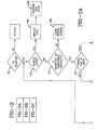
- FIGURE 2 which includes subfigures 2A, 2B, and 2C, is a flow diagram of one method of the present invention for carrying out the alignment of a vehicle chassis.
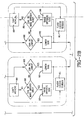
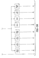
- FIGURE 3 which includes subfigures 3A, 3B, and 3C, is a flow diagram of a modified method for alignment of the vehicle chassis.
- FIGURE 4 is a diagrammatic representation of the manner in which the vehicle chassis is aligned by the methods shown by the flow diagrams of FIGURES 2 and 3 .
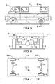
- FIGURE 5 is a diagrammatic side view of a vehicle to be aligned by the method and system of the present invention.
- FIGURE 6 is an enlarged fragmentary sectional view taken on line 6-6 in FIGURE 5 .
- FIGURE 7 is a diagrammatic view looking in the direction of line 7-7 in FIGURE 5 .
- FIGURE 8 is a diagrammatic plan view of the suspension system and control panel located within the vehicle.
- chassis generally refers to the sprung mass of the vehicle, which typically includes one or more of the components supported on the fluid suspension members. This can include, but is not limited to, a frame, a subframe, a floor and/or a body of the vehicle, for example.
- level, leveling and the like as used herein, such as in the term “horizon leveling,” for example, are not intended to be in any way limited to horizontal or vertical leveling. Rather, such terms refer to substantial alignment with a predetermined datum regardless of the orientation of the predetermined datum.
- FIGURE 1 is a diagrammatic representation of the horizon leveling system of the present invention which is indicated generally at 1, and illustrated as being used on a vehicle 2, such as an RV.
- system 1 can be used on other types of vehicles such as travel trailers, over-the-road truck trailers, ambulances, and personnel transport vehicles, for example.
- the system can also be used on stationary equipment, such as a gun platform, for example, that is supported on fluid suspension members, such as air springs, for example.
- Vehicle 2 includes a plurality of wheels 3, one of which is illustrated on each corner of the vehicle, and a fluid suspension system FSS.
- the fluid suspension system includes air springs 6, 7, 8 and 9 mounted adjacent each wheel 3 on the ends of supporting front and rear axles 11 and 12 and supports a vehicle chassis 4 thereon. For smaller vehicles, only a single axis having a pair of air springs may be utilized. However, for most RVs or other large pieces of equipment or vehicles, at least a pair of axles will be utilized having one or more air springs adjacent each end thereof
- the air springs are of a usual construction having a pair of spaced end members 15 and 16 ( FIGURES 5 and 6 ) with an intervening flexible sleeve 17 forming an internal fluid chamber.
- Some examples of known air springs are shown in U.S. Patent Nos. 5,374,037 , 4,852,861 , and 4,718,650 .
- Air-over-damper type suspension members also can be used within the scope of the present invention, such as is shown in U.S. Patent No. 4,712,776 .
- Leveling system 1 includes a compressor 20, which can be electrically operated or driven by the engine of the vehicle or in another suitable manner, to supply pressurized fluid, usually air, through a supply line 21 to a reservoir or supply tank 22. It will be appreciated that such compressors are known to be operable independent of the engine of the vehicle.
- a dryer 23 can optionally be included and is preferably fluidically interconnected along line 21 for removing moisture from the pressurized fluid prior to entering reservoir 22 . If desired, pressurized fluid can be supplied directly to the air springs from the compressor without first going to reservoir 22.
- a main control valve assembly 25 includes an inlet valve 26, an exhaust valve 27 and individual air spring control valves 28, 29, 30 and 31.
- Inlet valve 26 is in fluid communication with reservoir 22 through fluid supply line 33 and exhaust valve 27 is in fluid communication with an exhaust silencer 34.
- Individual control valves 28, 29, 30 and 31 are connected in fluid communication with individual air springs 6, 7, 8 and 9, respectively, by fluid lines 35, 36, 37 and 38, respectively.
- valve assembly 25 described above and illustrated in FIGURE 1 is merely one example of a suitable valve assembly and that any other suitable arrangement can be used without departing from the principles of the present invention.
- multi-position valves such as 2-way or 3-way valves for example, could be used in place of one or more of the control valves shown and described.
- Each of the air springs can optionally have a height sensor or detector, indicated generally at 40, associated therewith that can be any one of various known constructions.
- Height sensors 40 could utilize the Hall effect, sonics, infrared, resistance, or the like, that operate on, in or merely in association with the air springs and of which all are well known in the air spring art.
- Some examples of such air spring height detectors that are part of an air spring itself are shown in U.S. Patent Nos. 6,707,045 , 5,229,829 , and 4,798,369 .
- height sensor 40 can be a separate component externally supported on the vehicle and extending between spaced-apart portions of the vehicle, such as between the axle and chassis or vehicle body, for example.
- Each height sensor 40 is preferably supported adjacent one of the individual air springs and is also in communication with an electronic control unit (ECU) 42, such as by a control line 43.
- ECU electronice control unit
- an end-of-travel signal can be output by the height sensors indicating that one of the extreme positions, such as fully extended or fully compressed, for example, of the associated air spring has been reached or is being approached.
- end-of-travel data can be determined by the ECU based upon a comparison of the signal from the height detector with known end-of-travel values stored within the ECU.
- ECU 42 is shown in FIGURE 1 as being connected to an optional service switch 45 by control line 46 for selectively actuating the hydraulic jacks that are optionally provided on many RVs.
- the switch can also include ON and/or OFF positions ( FIGURE 8 ) for the automatic leveling system used during operation of the vehicle.
- ECU 42 also is connected to a height switch 49 by a control line 50, to the key actuated vehicle ignition switch 51 by a control line 52, and to a pair of indicating lights 55 and 56 by control lines 57 and 58, respectively.
- Height switch 49 can optionally be a multi-position height selection switch for use when the vehicle is selectively operable at a plurality of heights.
- ECU 42 also is operatively connected to the vehicle speed indicator or speedometer 59 by a control line 60, and to the individual air spring control valves in valve control unit 25 by a plurality of control lines, indicated collectively at 61. As such, ECU 42 is adapted to selectively actuate one or more of the plurality of valves. It will be appreciated that any suitable speed or movement indicating device can be operatively connected to the ECU in addition to or as an alternative to speedometer 59.
- CAN bus communications systems are well known and commonly used. These systems can include a standalone controller or alternately be integrated into another controller of the vehicle, such as ECU 42, for example.
- a suitable standard or protocol for such systems is SAE J1939. Though, it will be appreciated that a variety of other protocols exist and could alternately be used, such as CANOpen and DeviceNET, for example.
- One advantage of using a CAN bus communication system is that the actual physical wiring of the vehicle is greatly simplified. Another advantage is that the addition of a new device and/or system can be accomplished without significant physical modification of the vehicle.
- the new system can be added to the vehicle simply by suitably mounting a new device on the vehicle, placing the device into communication with the CAN bus communication system, and making any attendant software and/or firmware modifications to the existing devices and/or components. Once installed, the new system can send and receive any other signals, information and/or data through the CAN bus communication system to operate the newly added system.
- an alignment sensor or level detection device which is indicated generally at 65 and shown diagrammatically in FIGURES 5-7 , is mounted on or operatively connected to vehicle chassis 4.
- Device 65 provides an alignment signal to ECU 42 through a control line 66.
- the alignment signal is indicative of the orientation of the vehicle chassis.
- Level detection device 65 can be of any suitable type of apparatus, such as an accelerometer, tilt sensor, gyroscopic sensor, and a transducer or other device that can detect the position, orientation or amount of tilt of a structural body and provide a signal, such as a relative voltage or current, as to the approximate position, orientation or amount of tilt of the structural body associated therewith.
- One particular type of level detection device is a dual-axis accelerometer manufactured by Memsic, Inc.
- Accelerometer 65 provides an analog or digital value or signal that is dependent upon the tilt or out of level of the vehicle chassis upon which the sensor is supported. This signal is supplied to ECU 42 through line 66. Accelerometer 65 can be attached to any part of the vehicle chassis without effecting the invention. For example, the accelerometer could be secured to a portion of a frame, such as a cross beam, or to a portion of the body, such as a roof, side wall or floor. Additionally, the accelerometer can optionally be mounted centrally on the vehicle chassis. However, central mounting is not required.
- a typical air suspension system for a vehicle as described above is utilized without material modifications thereto with the exception of incorporating an alignment sensor or level detection device 65 that is operationally connected to ECU 42, in combination with the appropriate software utilized by ECU 42, to provide the features set forth in FIGURES 2-4 , and discussed below.
- FIGURE 8 represents a type of control panel 70 which can be located on the dashboard of the vehicle for controlling both the ride suspension system for the vehicle during the dynamic operation thereof as well as the horizon leveling system of the present invention.
- Panel 70 includes height switch 49 that controls the usual ride leveling system for the vehicle, indicating lights 55 and 56, the service switch 45, and a horizon leveling switch 72 that is connected to ECU 42 by a control line 73 ( FIGURE 1 ).
- An indication light 74 is connected to ECU 42 by a control line 69.
- Service switch 45 will be moved to one of three positions as shown in FIGURE 8 . The switch position can be illuminated by back lighting to indicate the selected position.
- panel 70 could be a touch screen which would eliminate the toggle or rocker switches discussed above.
- an artificial level position or horizon is indicated schematically by dot-dash line 71 ( FIGURES 5 and 6 ).
- This artificial horizon is programmed into ECU 42 as the predetermined datum.
- the predetermined datum is an imaginary reference plane that the system uses to align the vehicle chassis irrespective of the orientation of the axles, wheels of the vehicle or the supporting ground.
- FIGURE 2 The steps for carrying out one embodiment of the present invention are illustrated in FIGURE 2 , with a second embodiment being illustrated in FIGURE 3 , by the flow charts contained therein.
- the vehicle operator after the vehicle comes to a stop in an area such as a parking lot, campground, or the like, will actuate the horizon leveling system by actuating control switch 72 located on panel 70 in the cab portion of the vehicle, as indicated by block 75 ( FIGURE 2A ). In one preferred arrangement, this is done by depressing and holding control switch 72 for a predetermined period of time. A similar button hold can also be used to disengage the system.
- a suitable duration for holding the switch in the depressed position is from about 3 to about 10 seconds and preferably about 4 seconds.
- ECU 42 initially determines whether the vehicle chassis is aligned with the predetermined datum at block 77 by comparing the signals received from accelerometer 65 with respect to the artificial horizon 71 preset in ECU 42. If the vehicle floor or other reference plane is within an acceptable range on either side of artificial horizon 71, the ECU will send a signal and actuate indicator light 74, as represented by block 78, which will visually advise the driver that the vehicle is properly aligned. If the ECU senses that the vehicle chassis is out of alignment with the predetermined datum, it will then determine if the magnitude that the vehicle chassis is out of alignment is within the capability of the system to correct at block 79.
- the ECU will then proceed to block 81 where it will detect which side of the vehicle is above artificial horizon 71, that is, right side 62 or left side 63, as shown in FIGURE 7 .
- block 85 determines whether it can be lowered sufficiently to correct for the detected unevenness, and if permissible, block 86 provides the signal to lower the appropriate air spring by exhausting air therefrom, such as from air spring 6 since this is the air spring on the rear right side of the vehicle chassis.
- block 88 determines if the opposite side 63 can be raised sufficiently to compensate for the unevenness. If not, block 89 flashes indicating light 74 alerting the driver that the system is still checking if the proper alignment can be achieved. If left side 63 can be raised sufficiently, block 90 through block 84 then determines, as discussed above, if the front or rear of the left side is out of alignment, and whether it can be lowered to reach the desired aligned position.
- a timer circuit represented by block 92 rechecks the alignment of the vehicle chassis after a preset time period, such as one, two, etc., hours by the previous described sequence, and will make the needed correction, preferably by exhausting air from the high side air springs, in order to maintain the system alignment.
- left side 63 of the vehicle is determined by block 81 to be the high side, the same procedure is performed as discussed above for the right side.
- the front end is determined to be out of level at block 84 , the same procedure is performed for the front end as discussed above for the rear end. It is preferred that the air spring or springs on the high side or end be lowered before the air spring or springs on the lower side or end be raised since this involves only exhausting air from the individual air spring which will not deplete the supply of pressure air in reservoir 22. However, if necessary, the appropriate air spring can be raised by supplying it with additional pressurized fluid from reservoir 22. This feature avoids prematurely using the supply of pressurized fluid from reservoir 22.
- the ECU initially determines, depending upon the reading received from level indicating device 65, whether the amount of unevenness is too great to be compensated for by the system and to initially alert the operator to relocate the vehicle. This avoids the need to attempt the alignment of the vehicle body by actuation of the appropriate air springs only then to find out that the vehicle body cannot be aligned due to the excessive unevenness of the terrain. This saves time and unnecessary manipulation of the air spring components, fluid supplies, etc. Also, the system determines which side of the vehicle is the high side and then whether it can be compensated and, again, whether this unevenness can be compensated for and then which corner or end of the high side can be lowered to bring the vehicle body into alignment with the artificial horizon or predetermined datum stored in ECU 42.
- air is preferably exhausted from the high side air springs or just a corner air spring rather than introduce air into the lower air springs to achieve the desired level to conserve the stored pressurized fluid.
- the vehicle chassis was initially raised to achieve the levelness, it would make the ingress and egress slightly more difficult.
- it is not the height of the vehicle chassis above the wheels or axles that is controlling; it is the adjusting of the alignment of the vehicle body to a preset artificial horizon that is utilized by the improved system of the present invention.
- ECU 42 preferably includes a standard microchip that can be programmed by one skilled in the art to provide those features discussed above and shown in FIGURES 2-4 .
- FIGURES 3A-3C A modified embodiment of the improved method is shown in FIGURES 3A-3C .
- the system proceeds to the blocks of FIGURE 3C which then determines at block 101 whether the location that is out of alignment can be sufficiently lowered and, if so, whether it would be the lower side as determined by block 102 or lower corner as determined by block 103. Again, if the out of alignment location cannot be effectively lowered, the system then determines, as shown by the alternate blocks in FIGURE 3C , whether the opposite location, whether it be a side, end, or corner, can be raised to compensate for the misalignment. Again, light 74 will be flashed as shown by blocks 105 if aligning the misaligned area cannot be achieved, in a similar manner as discussed above for the embodiment of FIGURE 2 .
- the appropriate air spring is actuated through the appropriate control valve 28-31 for exhausting air from one or more of the air springs or, if necessary, to supply air to the appropriate air spring via the associated control valve to raise the unlevel corner, side, or end of the vehicle chassis.
- the difference between the method of FIGURES 2 and 3 is that the method shown by the flow diagrams in FIGURE 2 initially determine which side is out of alignment, after which it is determined whether it is the front or rear of that side that needs to be adjusted, whereas the method depicted by the flow diagram of FIGURE 3 determines immediately which location of the vehicle chassis is out of alignment for subsequent correction.
- FIGURE 4 is another diagrammatic representation of how the system functions to achieve the alignment with respect to the analog or digital signal supplied by accelerometer 65.
- Center point 110 represents the exact alignment in both the X and Y axis determined by accelerometer 65.
- the accelerometer will output signals corresponding to a midrange value or a value around the accelerometer's calibrated midpoint 110 from both the X and Y axis readings which indicates that both planes are level with the predetermined datum.
- the inner dot-dash circle 111 represents that position which, when reached, will indicate that the vehicle chassis or, alternatively, the floor or other part of the vehicle chassis being monitored, is substantially aligned with the predetermined datum.
- Outer concentric circle 112 represents the maximum unlevelness that can be compensated for by the vehicle and its suspension system.
- FIGURE 4 upon the output signal exceeding the value represented by circle 112, it will indicate that the misalignment or tilt is excessive and cannot be compensated for by the vehicle suspension system, such as represented by block 79 of FIGURE 2A or other blocks 89, FIGURES 2B and 2C .
- the two signals provided by accelerometer 65 intersect at point 113, which indicates that the front part and left side must be lowered until this point reaches inner circle 111. If the measured point falls within inner circle 111, no further alignment is required by the system. It will be appreciated that such a determination of excessive misalignment can be used in addition to or as an alternative to the end-of-travel analysis described above. However, should this point value fall outside of outer circle 112, such as shown by point 115, the system then indicates that too great a degree of misalignment exists and the capability of the suspension system to correct the misalignment is exceeded.
- the initial orientation of the chassis is indicated by the point 113 and the partially leveled condition is indicated by point 113'.
- an indication such as a flashing light or an audible signal, for example, can be output, such as from control panel 70, for example, to the operator of the vehicle to indicate that the vehicle has been partially leveled but remains outside of the fully leveled condition.
- the operator is given the option to reposition the vehicle for full leveling or accept the existing partially leveled condition.
- the artificial horizon or predetermined datum referred to herein is not in any way limited to a horizontal or substantially horizontal plane. Rather the predetermined datum can be a plane aligned in any desired orientation relative to the X-axis, Y-axis or any combination thereof without departing from the principles of the present invention.
- One method of calibrating the predetermined datum includes physically positioning the vehicle chassis in the desired orientation, such as where the floor of the chassis is substantially horizontal or tilting from back to front with the front being substantially lower than the bask, for example. Once the vehicle chassis is physically oriented, a signal indicating the orientation is acquired from the alignment sensor and the data associated with the signal is stored in the ECU as alignment data. Thereafter, the system operates as discussed above and repeatedly compares the signal's output from the alignment sensor to the alignment data in the ECU.
- the improved system and method of the present invention enables a vehicle chassis and, in particular, the floor or other wall of an RV, trailer or other structure, to be aligned easily and efficiently by utilizing the existing air suspension ride system of the vehicle, by the addition of accelerometer 65 or other type of alignment sensor in combination with ECU 42, which has been programmed according to the flow diagrams shown in FIGURES 2 and 3 .
- ECU 42 interprets the return values from the X and Y plane readings provided by accelerometer 65 and makes height adjustments to the vehicle via the height control componentry and, in particular, the ride suspension air springs, in order to get the vehicle chassis aligned with the predetermined datum, irrespective of the orientation of the ground, wheels or axles of the vehicle.
- the system preferably uses the existing ECU unit which is used for the normal ride suspension system and leveling with various modifications thereto in order to achieve the flow diagram and the results shown in FIGURES 2 and 3 .
- the control system of the present invention also is provided with suitable interlocks that act to selectively deactivate at least a portion of the horizon leveling system and returns the system to the normal ride height leveling upon actuation of switches 45 and/or 49. Immediately upon any of these switches being actuated, the ECU preferably automatically disengages the automatic leveling system of the present invention. Also, speedometer 59 and/or another suitable movement-sensing component is preferably connected with ECU 42 , such as through line 60, for example, to further signal ECU 42 to selectively deactivate the horizon leveling system upon the vehicle being put into motion.
- one of the alignment sensor and at least a portion of the ECU can be deactivated. Also, leaving “Park” or releasing the emergency brake could optionally signal ECU 42 to disengage the leveling system.
- the system initially attempts to adjust the height of the vehicle by exhausting air from the high side or end air springs to conserve the stored pressurized fluid in the reservoir 22. However, if necessary, air can be supplied to the appropriate air springs from reservoir 22 through the appropriate individual control valves 28-31 to raise that portion of the vehicle body to compensate for any misalignment if necessary and/or if desired.
- air suspension ride systems other than that shown in FIGURE 1 , could be utilized without affecting the concept of the invention, since one of the main features is the setting of the artificial horizon level and the adjusting of the appropriate air spring/springs to achieve this position, which is determined through an alignment sensor or level detection device, such as accelerometer 65, for example. Again, other types of level detecting devices could be utilized without affecting the concept of the invention.
- the present system can be used on stationary equipment other than vehicles, and the air springs replaced with hydraulic pressure members, etc., without effecting the invention.
Landscapes
- Engineering & Computer Science (AREA)
- Mechanical Engineering (AREA)
- Vehicle Body Suspensions (AREA)
- Automobile Manufacture Line, Endless Track Vehicle, Trailer (AREA)
- Automatic Cycles, And Cycles In General (AREA)
Abstract
Description
- This application claims priority from
U.S. Provisional Patent Application No. 60/463,487 filed on April 17, 2003 - The present invention broadly relates to air suspension systems and, more particularly, an electronically controlled air suspension system for use in association with a stationary vehicle that adjusts the air springs of the stationary vehicle to place the vehicle chassis thereof in substantial alignment with an artificial horizon or other predetermined datum.
- The present invention finds particular application in association with the use of larger mobile vehicles, such as recreational vehicles (RVs), travel trailers and over-the-road truck trailers, for example, and will be described herein with particular reference thereto. However, it is to be understood that such vehicles are simply exemplary structures and that the present invention is capable of broader application in association with the alignment of a wide variety of structures and vehicles. Further examples of such structures and vehicles include gun platforms, military and civilian personnel transport vehicles, and ambulances.
- Many larger vehicles, such as RVs, travel trailers, over-the-road truck trailers and the like, have an air suspension system for regulating the height of the vehicle chassis relative to the supporting axles, in a manner that is dependent upon the load placed in the vehicle, to adjust the height of the chassis in response to the ride conditions experienced by the vehicle. These suspension systems usually consist of a plurality of fluid suspension members, such as air springs, which support the vehicle chassis above the axles. The height of the air springs is controlled by the ingress and egress of pressurized fluid from a suitable source mounted on the vehicle, such as a compressor. One or more intervening valves are traditionally used to facilitate the ingress and egress of pressurized fluid respectively into and out of the air springs, thus adjusting the height of the air springs and correspondingly the position of the vehicle chassis relative to the vehicle axles. Such systems also enable the vehicle chassis to be maintained in an orientation substantially aligned with the axles while the vehicle is stationary. This is accomplished by individually regulating the heights of the air springs that support the vehicle chassis on the axles. One disadvantage of such systems, though, is that the chassis can only be positioned relative to the axles. So, if the axles are disposed in an undesirable orientation, the chassis, though level with the axles, will also be disposed in an undesirable orientation.
- As an alternative, many of these vehicles, such as RVs, will also use a plurality of hydraulic jacks, which are lowered in order to level the floor of the RV when in a stationary, parked condition. However, in certain situations, the use of hydraulic jacks is not permitted, such as when the RV is parked on an asphalt parking lot since the jacks could damage the asphalt. Thus, leveling of the vehicle cannot be accomplished under these circumstances. Another disadvantage is the cost associated with these systems, as few of the standard components of the vehicle are utilized therein. That is, the hydraulic jacks, the control valves, the hydraulic lines, the electronic control unit, and the user interface, as well as other components, must be installed on the vehicle, over and above all of the standard components that are already installed. Thus, these extra components increase the cost of the vehicle in order to obtain the leveling feature.
- Also, some RVs may use the existing suspension air springs to adjust the floor height and to level the floor by the use of mercury switches, or other controls which will raise and lower certain of the air springs to regulate the height of the floor with respect to the vehicle axles until a level condition is reached. Some examples of such fluid actuated leveling systems for trailers, RVs, etc., are shown in
U.S. Patent Nos. 5,228,704 ,5,465,209 ,5,180,024 ,5,499,845 ,6,431,557 , and6,428,026 . However, it will be appreciated that these systems may be useful in situations where weight distribution changes in a parked or otherwise stationary vehicle. However, these systems remain ineffective for leveling a vehicle chassis when the axles of the vehicle are not themselves in a level orientation. - The above-listed patents disclose numerous leveling and suspension control systems for air springs in vehicles, some of which are operational while the vehicle is moving, while others are actuated when the vehicle is stationary. Most of these systems use the air springs to regulate the height of the vehicle chassis with respect to the axles or the wheel supporting structure in order to achieve a level condition. Also, many of these systems require separate control systems which are in addition to the existing suspension components and pneumatic ride control system of the vehicle.
- For at least these reasons, it is considered desirable to develop an air suspension system that overcomes these as well as other disadvantages.
Attention is also drawn to the disclosure ofJP-04-071918A
The present invention in one aspect provides a method of positioning a vehicle chassis of a vehicle in approximate alignment with a predetermined datum, the vehicle having at least one axle and a fluid suspension system, the predetermined datum being an imaginary reference plane independent of the distance of the vehicle chassis from the axles or wheels, the fluid suspension system comprising a plurality of fluid suspension members disposed between the axle and the chassis, a control device, a pressurized fluid source and an exhaust passage in fluid communication with the plurality of fluid suspension members through the control device, and an electronic control unit operatively associated with the control device, the method comprising steps of: - a) providing an alignment sensor supported on the chassis for outputting a signal indicative of the orientation of the chassis to the electronic control unit;
- b) acquiring a signal output by the alignment sensor;
- c) comparing the signal from the alignment sensor to data associated with the orientation of the predetermined datum and stored in the electronic control unit as alignment data;
- d) determining which of the right front, left front, left rear, right rear, entire front, entire rear, entire left side or entire right side is the high location of the vehicle chassis;
- e) determining whether the high location can be lowered sufficiently to bring the vehicle chassis into approximate alignment with the predetermined datum; and,
- f) selectively operating the control device to permit fluid communication between the appropriate one or more fluid suspension members and the fluid exhaust until the signal from the alignment sensor approximately corresponds to the alignment data.
- a plurality of fluid suspension members adjustably supporting the chassis on an axle of the stationary vehicle;
- a pressurized fluid source operatively connected to the fluid suspension members;
- a control device operatively connected between the fluid source and the fluid suspension members for controlling pressurized fluid flow to and from the fluid suspension members;
- an alignment sensor supported on the chassis for outputting a signal indicative of the orientation of the chassis; and,
- an electronic control unit operatively connected to the control device and the alignment sensor, the electronic control unit receiving the signal from the alignment sensor and operative to:
- compare the signal from the alignment sensor to data associated with the orientation of the predetermined datum and stored in the electronic control unit as alignment data;
- determine which of the right front, left front, left rear, right rear, entire front, entire rear, entire left side or entire right side is the high location of the vehicle chassis;
- determine whether the high location can be lowered sufficiently to bring the vehicle chassis into approximate alignment with the predetermined datum; and,
- selectively activate the control device to adjust the appropriate one or more fluid suspension members until the signal from the alignment sensor is indicative of the chassis being approximately aligned with the predetermined datum.
- A method of positioning a vehicle chassis of a vehicle in approximate alignment with a predetermined datum is provided. The vehicle has an axle and a fluid suspension system. The fluid suspension system consists of a plurality of fluid suspension members, a control device, a pressurized fluid source and an exhaust passage. The fluid suspension members are disposed between the axle and the chassis of the vehicle. The pressurized fluid source and the exhaust passage are in fluid communication with the plurality of fluid suspension members through the control device. The vehicle also includes an electronic control unit operatively associated with the control device. The method includes steps of providing an alignment sensor supported on the chassis for outputting a signal indicative of the orientation of the chassis to the electronic control unit and acquiring a signal output by the alignment sensor. Another step includes comparing the signal from the alignment sensor to alignment data stored in the electronic control unit. A further step includes selectively operating the control device to permit fluid communication between one or more of the fluid suspension members and one of the pressurized fluid source and the fluid exhaust until the signal from the alignment sensor approximately corresponds to the alignment data.
- A control system adapted to position a vehicle chassis of a stationary vehicle in substantial alignment with a predetermined datum is provided and includes a plurality of fluid suspension members adjustably supporting the chassis on an axle of the stationary vehicle. A pressurized fluid source is operatively connected to the fluid suspension members. A control device is operatively connected between the fluid source and the fluid suspension members for controlling pressurized fluid flow to and from the fluid suspension members. An alignment sensor is supported on the chassis for outputting a signal indicative of the orientation of the chassis. An electronic control unit is operatively connected to the control device and the alignment sensor. The electronic control unit is for receiving the signal from the alignment sensor and selectively activating the control device to adjust one or more of the fluid suspension members until the signal from the alignment sensor is indicative of the chassis being approximately aligned with the predetermined datum.
- A method of positioning a vehicle chassis of a stationary vehicle in approximate alignment with a predetermined datum is provided. The vehicle has an axle and a fluid suspension system. The fluid suspension system includes a plurality of fluid suspension members, a control device, a pressurized fluid source and an exhaust passage. The fluid suspension members are disposed between the axle and the chassis of the vehicle. The pressurized fluid source and the exhaust passage are in fluid communication with the plurality of fluid suspension members through the control device. The vehicle also includes an electronic control unit operatively associated with the control device. The method includes steps of providing an alignment sensor supported on the chassis for outputting a signal indicative of the orientation of the chassis to the electronic control unit and acquiring a signals output by the alignment sensor. Another step includes comparing the signal from the alignment sensor to alignment data stored in the electronic control unit. A further step includes selectively operating the control device to permit fluid communication between one or more of the fluid suspension members and one of the pressurized fluid source and the fluid exhaust until the signal from the alignment sensor approximately corresponds to the alignment data.
- The present invention provides an electronic control system for leveling a vehicle chassis, such as the frame, subframe, floor and/or body of an RV or over-the-road trailer, for example, which uses the existing air suspension components for the vehicle ride system, avoiding additional and costly duplicate components and additional space usage in order to provide the desired leveling effect for the vehicle chassis, especially when the vehicle is stationary.
- Another feature of the invention is to provide a leveling system that requires only the addition of an alignment sensor or other level detection device, such as an accelerometer, tilt sensor, gyro, or similar type sensor, for example. The alignment sensor is supported on the vehicle chassis and operationally connected with an electronic control unit (ECU), which is used to control the ride suspension system in combination with software for the ECU for performing a method of the present invention.
- Still another feature of the invention is to provide a horizon leveling control system that aligns the vehicle chassis with respect to an artificial horizon or other predetermined datum independent of the distance of the vehicle chassis from the axles or wheels, by introducing this artificial horizon or predetermined datum into the software of the ECU.
- Another feature of the invention is to provide the system with an interlock via the standard height leveling system to ensure that the ECU automatically disengages the horizon leveling system of the invention and goes to the normal ride height leveling upon movement of the vehicle or placement of the vehicle in a transmission gear in preparation for subsequent movement.
- A further aspect of the invention is to enable the system to determine whether the individual air springs have sufficient travel to enable the vehicle to achieve a level condition after the tilt or orientation of the vehicle is initially determined by the system before attempting to perform the actual leveling by introducing or exhausting air into or from selected air springs.
- A further feature of the invention is the ability to regulate the heights of the individual air springs in a particular sequence, such as initially adjusting for large magnitudes of unevenness by adjusting the air springs on one side of the vehicle, after which smaller magnitudes of height can be compensated for by individually adjusting either the front or rear air spring on the selected one side of the vehicle.
- Still another advantage of the present invention is to enable the system to initially exhaust air from the air springs on a high side or corner of the vehicle after the unevenness is detected by the level detection device, prior to introducing additional pressurized fluid into one or more of the air springs to raise a lower side, thereby reducing the depletion of the supply of pressurized fluid and minimizing additional work by the vehicle compressor.
- In summary, the invention provides a horizon leveling system that utilizes most of the features and components of the air suspension ride system of a vehicle, such as an RV, travel trailer or over-the-road trailer, for example, by the addition of a level detection device and by programming the ECU with an artificial horizon or other predetermined datum. The present system is adapted to adjust the orientation of the vehicle chassis into alignment with the artificial horizon irregardless of the position of the vehicle axles.
The method of the invention may further comprise steps of providing end-of-travel data indicative of an extreme orientation of the chassis, storing the end-of-travel data within the electronic control unit, acquiring a signal from the alignment sensor indicative of the orientation of the chassis, and comparing the signal to the end-of-travel data prior to step f).
The method of the invention may also further comprise a step of providing a height detector supported between the axle and the chassis, the height detector outputting a signal indicative of the position of the chassis relative to the axle.
In this case, the method can further comprise steps of providing end-of-travel data indicative of an extreme position of the chassis relative to the axle, storing the end-of-travel data within the electronic control unit, acquiring a signal from the height detector indicative of the position of the chassis relative to the axle, and comparing the signal to the end-of-travel data prior to step f).
This method can further comprise steps of determining whether the difference between the signal from the height detector and the end-of-travel data exceeds a predetermined value, and the electronic control unit selectively operating the control device to discontinue pressurized fluid flow therethrough if the predetermined value is exceeded. - The invention will be further described with reference to the accompanying drawings.
-
FIGURE 1 is a schematic diagram of the horizon leveling system and components thereof mounted on a traditional dual axle vehicle. -
FIGURE 2 , which includes subfigures 2A, 2B, and 2C, is a flow diagram of one method of the present invention for carrying out the alignment of a vehicle chassis. -
FIGURE 3 , which includes subfigures 3A, 3B, and 3C, is a flow diagram of a modified method for alignment of the vehicle chassis. -
FIGURE 4 is a diagrammatic representation of the manner in which the vehicle chassis is aligned by the methods shown by the flow diagrams ofFIGURES 2 and3 . -
FIGURE 5 is a diagrammatic side view of a vehicle to be aligned by the method and system of the present invention. -
FIGURE 6 is an enlarged fragmentary sectional view taken on line 6-6 inFIGURE 5 . -
FIGURE 7 is a diagrammatic view looking in the direction of line 7-7 inFIGURE 5 . -
FIGURE 8 is a diagrammatic plan view of the suspension system and control panel located within the vehicle. - Similar numerals refer to similar parts throughout the drawings.
- It is to be understood that the term chassis, as recited herein, generally refers to the sprung mass of the vehicle, which typically includes one or more of the components supported on the fluid suspension members. This can include, but is not limited to, a frame, a subframe, a floor and/or a body of the vehicle, for example. Additionally, the terms level, leveling and the like as used herein, such as in the term "horizon leveling," for example, are not intended to be in any way limited to horizontal or vertical leveling. Rather, such terms refer to substantial alignment with a predetermined datum regardless of the orientation of the predetermined datum.
-
FIGURE 1 is a diagrammatic representation of the horizon leveling system of the present invention which is indicated generally at 1, and illustrated as being used on avehicle 2, such as an RV. However,system 1 can be used on other types of vehicles such as travel trailers, over-the-road truck trailers, ambulances, and personnel transport vehicles, for example. The system can also be used on stationary equipment, such as a gun platform, for example, that is supported on fluid suspension members, such as air springs, for example.Vehicle 2 includes a plurality ofwheels 3, one of which is illustrated on each corner of the vehicle, and a fluid suspension system FSS. The fluid suspension system includes air springs 6, 7, 8 and 9 mounted adjacent eachwheel 3 on the ends of supporting front andrear axles - The air springs are of a usual construction having a pair of spaced
end members 15 and 16 (FIGURES 5 and 6 ) with an interveningflexible sleeve 17 forming an internal fluid chamber. Some examples of known air springs are shown inU.S. Patent Nos. 5,374,037 ,4,852,861 , and4,718,650 . Air-over-damper type suspension members also can be used within the scope of the present invention, such as is shown inU.S. Patent No. 4,712,776 . - Leveling
system 1 includes acompressor 20, which can be electrically operated or driven by the engine of the vehicle or in another suitable manner, to supply pressurized fluid, usually air, through asupply line 21 to a reservoir orsupply tank 22. It will be appreciated that such compressors are known to be operable independent of the engine of the vehicle. Adryer 23 can optionally be included and is preferably fluidically interconnected alongline 21 for removing moisture from the pressurized fluid prior to enteringreservoir 22. If desired, pressurized fluid can be supplied directly to the air springs from the compressor without first going toreservoir 22. - A main
control valve assembly 25 includes aninlet valve 26, anexhaust valve 27 and individual airspring control valves Inlet valve 26 is in fluid communication withreservoir 22 throughfluid supply line 33 andexhaust valve 27 is in fluid communication with anexhaust silencer 34.Individual control valves fluid lines valve assembly 25 described above and illustrated inFIGURE 1 is merely one example of a suitable valve assembly and that any other suitable arrangement can be used without departing from the principles of the present invention. For example, multi-position valves, such as 2-way or 3-way valves for example, could be used in place of one or more of the control valves shown and described. - Each of the air springs can optionally have a height sensor or detector, indicated generally at 40, associated therewith that can be any one of various known constructions.
Height sensors 40 could utilize the Hall effect, sonics, infrared, resistance, or the like, that operate on, in or merely in association with the air springs and of which all are well known in the air spring art. Some examples of such air spring height detectors that are part of an air spring itself are shown inU.S. Patent Nos. 6,707,045 ,5,229,829 , and4,798,369 . However, as shown inFIGURE 6 ,height sensor 40 can be a separate component externally supported on the vehicle and extending between spaced-apart portions of the vehicle, such as between the axle and chassis or vehicle body, for example. Eachheight sensor 40 is preferably supported adjacent one of the individual air springs and is also in communication with an electronic control unit (ECU) 42, such as by acontrol line 43. Additionally, an end-of-travel signal can be output by the height sensors indicating that one of the extreme positions, such as fully extended or fully compressed, for example, of the associated air spring has been reached or is being approached. Alternately, end-of-travel data can be determined by the ECU based upon a comparison of the signal from the height detector with known end-of-travel values stored within the ECU.ECU 42 is shown inFIGURE 1 as being connected to anoptional service switch 45 bycontrol line 46 for selectively actuating the hydraulic jacks that are optionally provided on many RVs. Optionally, the switch can also include ON and/or OFF positions (FIGURE 8 ) for the automatic leveling system used during operation of the vehicle.ECU 42 also is connected to aheight switch 49 by acontrol line 50, to the key actuatedvehicle ignition switch 51 by acontrol line 52, and to a pair of indicatinglights control lines Height switch 49 can optionally be a multi-position height selection switch for use when the vehicle is selectively operable at a plurality of heights.ECU 42 also is operatively connected to the vehicle speed indicator orspeedometer 59 by acontrol line 60, and to the individual air spring control valves invalve control unit 25 by a plurality of control lines, indicated collectively at 61. As such,ECU 42 is adapted to selectively actuate one or more of the plurality of valves. It will be appreciated that any suitable speed or movement indicating device can be operatively connected to the ECU in addition to or as an alternative tospeedometer 59. - Many of the above-described components and manner of use are standard on many vehicle air suspension systems used for RVs and trailers to provide a multi-position leveling system and desired ride characteristic for the vehicle. Additionally, it will be appreciated that communications to and from the various devices and components of the vehicle, such as
ECU 42,height switch 49 andspeedometer 59, for example, can be transmitted in any suitable manner. For example, each of the devices and components can be hard-wired to one another as prescribed by each of the various systems operative on the vehicle, with the signals communicated between the devices and components along the individual wires. As an example, if five different systems of the vehicle rely upon a signal from the speedometer, five different wires may be interconnected to the speedometer to provide the signal output by the speedometer to each of the systems directly. However, many vehicles now include a CAN bus communication system that networks the various devices and components together. Such CAN bus communications systems are well known and commonly used. These systems can include a standalone controller or alternately be integrated into another controller of the vehicle, such asECU 42, for example. One example of a suitable standard or protocol for such systems is SAE J1939. Though, it will be appreciated that a variety of other protocols exist and could alternately be used, such as CANOpen and DeviceNET, for example. One advantage of using a CAN bus communication system is that the actual physical wiring of the vehicle is greatly simplified. Another advantage is that the addition of a new device and/or system can be accomplished without significant physical modification of the vehicle. For example, the new system can be added to the vehicle simply by suitably mounting a new device on the vehicle, placing the device into communication with the CAN bus communication system, and making any attendant software and/or firmware modifications to the existing devices and/or components. Once installed, the new system can send and receive any other signals, information and/or data through the CAN bus communication system to operate the newly added system. - In accordance with the invention, an alignment sensor or level detection device, which is indicated generally at 65 and shown diagrammatically in
FIGURES 5-7 , is mounted on or operatively connected to vehicle chassis 4.Device 65 provides an alignment signal toECU 42 through acontrol line 66. The alignment signal is indicative of the orientation of the vehicle chassis.Level detection device 65 can be of any suitable type of apparatus, such as an accelerometer, tilt sensor, gyroscopic sensor, and a transducer or other device that can detect the position, orientation or amount of tilt of a structural body and provide a signal, such as a relative voltage or current, as to the approximate position, orientation or amount of tilt of the structural body associated therewith. One particular type of level detection device is a dual-axis accelerometer manufactured by Memsic, Inc. of North Andover, MA, identified as model MXR299ML. This sensor operates on a thermal principle, generating a signal, such as an output voltage for example, for both the X-axis and Y-axis that varies according to the angular orientation of the sensor.Accelerometer 65 provides an analog or digital value or signal that is dependent upon the tilt or out of level of the vehicle chassis upon which the sensor is supported. This signal is supplied toECU 42 throughline 66.Accelerometer 65 can be attached to any part of the vehicle chassis without effecting the invention. For example, the accelerometer could be secured to a portion of a frame, such as a cross beam, or to a portion of the body, such as a roof, side wall or floor. Additionally, the accelerometer can optionally be mounted centrally on the vehicle chassis. However, central mounting is not required. - Thus, in accordance with one of the features of the invention, a typical air suspension system for a vehicle as described above, is utilized without material modifications thereto with the exception of incorporating an alignment sensor or
level detection device 65 that is operationally connected toECU 42, in combination with the appropriate software utilized byECU 42, to provide the features set forth inFIGURES 2-4 , and discussed below. -
FIGURE 8 represents a type ofcontrol panel 70 which can be located on the dashboard of the vehicle for controlling both the ride suspension system for the vehicle during the dynamic operation thereof as well as the horizon leveling system of the present invention.Panel 70 includesheight switch 49 that controls the usual ride leveling system for the vehicle, indicatinglights service switch 45, and ahorizon leveling switch 72 that is connected toECU 42 by a control line 73 (FIGURE 1 ). Anindication light 74 is connected toECU 42 by acontrol line 69.Service switch 45 will be moved to one of three positions as shown inFIGURE 8 . The switch position can be illuminated by back lighting to indicate the selected position. If desired,panel 70 could be a touch screen which would eliminate the toggle or rocker switches discussed above. - In accordance with one of the features of the invention, an artificial level position or horizon is indicated schematically by dot-dash line 71 (
FIGURES 5 and 6 ). This artificial horizon is programmed intoECU 42 as the predetermined datum. The predetermined datum is an imaginary reference plane that the system uses to align the vehicle chassis irrespective of the orientation of the axles, wheels of the vehicle or the supporting ground. Thoughline 71 shown inFIGURES 5 and 6 as being substantially horizontal, it will be appreciated thatline 71 could be disposed in any desired orientation as established hereinbefore. - The steps for carrying out one embodiment of the present invention are illustrated in
FIGURE 2 , with a second embodiment being illustrated inFIGURE 3 , by the flow charts contained therein. Referring toFIGURE 2 , the vehicle operator, after the vehicle comes to a stop in an area such as a parking lot, campground, or the like, will actuate the horizon leveling system by actuating control switch 72 located onpanel 70 in the cab portion of the vehicle, as indicated by block 75 (FIGURE 2A ). In one preferred arrangement, this is done by depressing and holdingcontrol switch 72 for a predetermined period of time. A similar button hold can also be used to disengage the system. Thus, the opportunity for inadvertently initiating (or alternately, disengaging) the system, such as by bumping the switch, for example, is minimized. One example of a suitable duration for holding the switch in the depressed position is from about 3 to about 10 seconds and preferably about 4 seconds. -
ECU 42 initially determines whether the vehicle chassis is aligned with the predetermined datum atblock 77 by comparing the signals received fromaccelerometer 65 with respect to theartificial horizon 71 preset inECU 42. If the vehicle floor or other reference plane is within an acceptable range on either side ofartificial horizon 71, the ECU will send a signal and actuateindicator light 74, as represented byblock 78, which will visually advise the driver that the vehicle is properly aligned. If the ECU senses that the vehicle chassis is out of alignment with the predetermined datum, it will then determine if the magnitude that the vehicle chassis is out of alignment is within the capability of the system to correct atblock 79. If outside the capability of the system, it will send a signal to the operator, such as an audible tone or a flashinglight 74, as shown byblock 80, which immediately advises the driver that the vehicle is excessively uneven and that the suspension system will not be able to sufficiently compensate for the uneven terrain on which the vehicle is currently parked. The driver can then reposition the vehicle at that location or go to a different, more level location. If the out-of-level signal generated byaccelerometer 65 is within the capability of the system to correct, the ECU will then proceed to block 81where it will detect which side of the vehicle is aboveartificial horizon 71, that is,right side 62 orleft side 63, as shown inFIGURE 7 . - Upon determining at
block 81 which is the high side of the vehicle, a determination then is made at block 82 (assuming for the purpose of this description that the right side was determined to be the high side) as to whether the amount of unevenness is within the capability of the suspension system to correct. If a determination is made that the right side can be lowered sufficiently atblock 82, a signal is then sent viablock 83 to block 84 (FIGURE 2C ) to determine if the front 62A or the rear 62B ofright side 62 is out of alignment. After the determination is made atblock 84 that the front or rear is out of alignment, block 85 determines whether it can be lowered sufficiently to correct for the detected unevenness, and if permissible, block 86 provides the signal to lower the appropriate air spring by exhausting air therefrom, such as fromair spring 6 since this is the air spring on the rear right side of the vehicle chassis. - If the
right side 62 cannot be lowered sufficiently, block 88 (FIGURE 2B ) determines if theopposite side 63 can be raised sufficiently to compensate for the unevenness. If not, block 89 flashes indicating light 74 alerting the driver that the system is still checking if the proper alignment can be achieved. Ifleft side 63 can be raised sufficiently, block 90 throughblock 84 then determines, as discussed above, if the front or rear of the left side is out of alignment, and whether it can be lowered to reach the desired aligned position. - Again, if the previously determined front or rear cannot be lowered, determination is made by
block 88 if the opposite front or rear can be raised. If not, block 91 flashes light 74 that the desired alignment has yet to be achieved. After alignment has been achieved and recognized atbloc 77 and the appropriate signal sent to light 74 viablock 78FIGURE 2A ), a timer circuit represented byblock 92, rechecks the alignment of the vehicle chassis after a preset time period, such as one, two, etc., hours by the previous described sequence, and will make the needed correction, preferably by exhausting air from the high side air springs, in order to maintain the system alignment. - It is understood that if
left side 63 of the vehicle is determined byblock 81 to be the high side, the same procedure is performed as discussed above for the right side. - Also, if the front end is determined to be out of level at
block 84, the same procedure is performed for the front end as discussed above for the rear end. It is preferred that the air spring or springs on the high side or end be lowered before the air spring or springs on the lower side or end be raised since this involves only exhausting air from the individual air spring which will not deplete the supply of pressure air inreservoir 22. However, if necessary, the appropriate air spring can be raised by supplying it with additional pressurized fluid fromreservoir 22. This feature avoids prematurely using the supply of pressurized fluid fromreservoir 22. - Thus, the ECU initially determines, depending upon the reading received from
level indicating device 65, whether the amount of unevenness is too great to be compensated for by the system and to initially alert the operator to relocate the vehicle. This avoids the need to attempt the alignment of the vehicle body by actuation of the appropriate air springs only then to find out that the vehicle body cannot be aligned due to the excessive unevenness of the terrain. This saves time and unnecessary manipulation of the air spring components, fluid supplies, etc. Also, the system determines which side of the vehicle is the high side and then whether it can be compensated and, again, whether this unevenness can be compensated for and then which corner or end of the high side can be lowered to bring the vehicle body into alignment with the artificial horizon or predetermined datum stored inECU 42. - Again, air is preferably exhausted from the high side air springs or just a corner air spring rather than introduce air into the lower air springs to achieve the desired level to conserve the stored pressurized fluid. Also, it is preferred to lower the vehicle chassis, sides, or corners to achieve the desired levelness as opposed to raising one side or corner thereof to achieve the desired levelness, since a lower vehicle chassis, when stationary, facilitates the ingress and egress of the occupants into and out of the vehicle chassis. Thus, if the vehicle chassis was initially raised to achieve the levelness, it would make the ingress and egress slightly more difficult. Again, it is not the height of the vehicle chassis above the wheels or axles that is controlling; it is the adjusting of the alignment of the vehicle body to a preset artificial horizon that is utilized by the improved system of the present invention.
-
ECU 42 preferably includes a standard microchip that can be programmed by one skilled in the art to provide those features discussed above and shown inFIGURES 2-4 . - A modified embodiment of the improved method is shown in
FIGURES 3A-3C . After a determination is made atblock 79 that the magnitude of unlevelness is within the capability of the system, a determination is then made atblock 100 as to what is the direction that is out of alignment, namely, as shown inFIGURE 3B , whether it is the right front, left front, left rear, right rear, or entire front, the entire rear, the entire left side, or the entire right side of the vehicle chassis. After this determination is made by one of the blocks as shown inFIGURE 3B , the system proceeds to the blocks ofFIGURE 3C which then determines atblock 101 whether the location that is out of alignment can be sufficiently lowered and, if so, whether it would be the lower side as determined byblock 102 or lower corner as determined byblock 103. Again, if the out of alignment location cannot be effectively lowered, the system then determines, as shown by the alternate blocks inFIGURE 3C , whether the opposite location, whether it be a side, end, or corner, can be raised to compensate for the misalignment. Again, light 74 will be flashed as shown byblocks 105 if aligning the misaligned area cannot be achieved, in a similar manner as discussed above for the embodiment ofFIGURE 2 . After it has been determined that the desired alignment can be achieved by lowering a particular location on the vehicle chassis, the appropriate air spring is actuated through the appropriate control valve 28-31 for exhausting air from one or more of the air springs or, if necessary, to supply air to the appropriate air spring via the associated control valve to raise the unlevel corner, side, or end of the vehicle chassis. - The difference between the method of
FIGURES 2 and3 is that the method shown by the flow diagrams inFIGURE 2 initially determine which side is out of alignment, after which it is determined whether it is the front or rear of that side that needs to be adjusted, whereas the method depicted by the flow diagram ofFIGURE 3 determines immediately which location of the vehicle chassis is out of alignment for subsequent correction. -
FIGURE 4 is another diagrammatic representation of how the system functions to achieve the alignment with respect to the analog or digital signal supplied byaccelerometer 65.Center point 110 represents the exact alignment in both the X and Y axis determined byaccelerometer 65. In this situation, the accelerometer will output signals corresponding to a midrange value or a value around the accelerometer's calibratedmidpoint 110 from both the X and Y axis readings which indicates that both planes are level with the predetermined datum. The inner dot-dash circle 111 represents that position which, when reached, will indicate that the vehicle chassis or, alternatively, the floor or other part of the vehicle chassis being monitored, is substantially aligned with the predetermined datum. Outerconcentric circle 112 represents the maximum unlevelness that can be compensated for by the vehicle and its suspension system. - In the particular example of
FIGURE 4 , upon the output signal exceeding the value represented bycircle 112, it will indicate that the misalignment or tilt is excessive and cannot be compensated for by the vehicle suspension system, such as represented byblock 79 ofFIGURE 2A orother blocks 89,FIGURES 2B and2C . As an example, assume that the two signals provided byaccelerometer 65 intersect at point 113, which indicates that the front part and left side must be lowered until this point reachesinner circle 111. If the measured point falls withininner circle 111, no further alignment is required by the system. It will be appreciated that such a determination of excessive misalignment can be used in addition to or as an alternative to the end-of-travel analysis described above. However, should this point value fall outside ofouter circle 112, such as shown bypoint 115, the system then indicates that too great a degree of misalignment exists and the capability of the suspension system to correct the misalignment is exceeded. - Under certain circumstances, it may be determined that the orientation of the chassis is or was within the capability of the suspension system to level but after one or more leveling operations a level condition cannot be achieved. These situations are represented by
blocks FIGURES 2B and2C , as well asblocks FIGURE 3C . An example of such a situation might be where the operator has inadvertently parked the vehicle adjacent a foreign object that impedes the lowering of a portion of the chassis. In such a situation, the suspension system could have the capacity to fully level the vehicle, but the foreign object will only permit the chassis to be partially leveled. InFIGURE 4 , for example, the initial orientation of the chassis is indicated by the point 113 and the partially leveled condition is indicated by point 113'. Under such a circumstance, an indication, such as a flashing light or an audible signal, for example, can be output, such as fromcontrol panel 70, for example, to the operator of the vehicle to indicate that the vehicle has been partially leveled but remains outside of the fully leveled condition. Thus, the operator is given the option to reposition the vehicle for full leveling or accept the existing partially leveled condition. - It is to be distinctly understood that the artificial horizon or predetermined datum referred to herein is not in any way limited to a horizontal or substantially horizontal plane. Rather the predetermined datum can be a plane aligned in any desired orientation relative to the X-axis, Y-axis or any combination thereof without departing from the principles of the present invention. One method of calibrating the predetermined datum includes physically positioning the vehicle chassis in the desired orientation, such as where the floor of the chassis is substantially horizontal or tilting from back to front with the front being substantially lower than the bask, for example. Once the vehicle chassis is physically oriented, a signal indicating the orientation is acquired from the alignment sensor and the data associated with the signal is stored in the ECU as alignment data. Thereafter, the system operates as discussed above and repeatedly compares the signal's output from the alignment sensor to the alignment data in the ECU.
- Thus, the improved system and method of the present invention enables a vehicle chassis and, in particular, the floor or other wall of an RV, trailer or other structure, to be aligned easily and efficiently by utilizing the existing air suspension ride system of the vehicle, by the addition of
accelerometer 65 or other type of alignment sensor in combination withECU 42, which has been programmed according to the flow diagrams shown inFIGURES 2 and3 .ECU 42 interprets the return values from the X and Y plane readings provided byaccelerometer 65 and makes height adjustments to the vehicle via the height control componentry and, in particular, the ride suspension air springs, in order to get the vehicle chassis aligned with the predetermined datum, irrespective of the orientation of the ground, wheels or axles of the vehicle. The system preferably uses the existing ECU unit which is used for the normal ride suspension system and leveling with various modifications thereto in order to achieve the flow diagram and the results shown inFIGURES 2 and3 . - The control system of the present invention also is provided with suitable interlocks that act to selectively deactivate at least a portion of the horizon leveling system and returns the system to the normal ride height leveling upon actuation of
switches 45 and/or 49. Immediately upon any of these switches being actuated, the ECU preferably automatically disengages the automatic leveling system of the present invention. Also,speedometer 59 and/or another suitable movement-sensing component is preferably connected withECU 42, such as throughline 60, for example, to further signalECU 42 to selectively deactivate the horizon leveling system upon the vehicle being put into motion. Thus, where the speedometer or other device output a signal indicative of a speed greater than about zero (0) mph, one of the alignment sensor and at least a portion of the ECU can be deactivated. Also, leaving "Park" or releasing the emergency brake could optionally signalECU 42 to disengage the leveling system. As discussed above, the system initially attempts to adjust the height of the vehicle by exhausting air from the high side or end air springs to conserve the stored pressurized fluid in thereservoir 22. However, if necessary, air can be supplied to the appropriate air springs fromreservoir 22 through the appropriate individual control valves 28-31 to raise that portion of the vehicle body to compensate for any misalignment if necessary and/or if desired. - It is readily understood that air suspension ride systems, other than that shown in
FIGURE 1 , could be utilized without affecting the concept of the invention, since one of the main features is the setting of the artificial horizon level and the adjusting of the appropriate air spring/springs to achieve this position, which is determined through an alignment sensor or level detection device, such asaccelerometer 65, for example. Again, other types of level detecting devices could be utilized without affecting the concept of the invention. Likewise, the present system can be used on stationary equipment other than vehicles, and the air springs replaced with hydraulic pressure members, etc., without effecting the invention. - While the invention has been described with reference to the foregoing embodiments and considerable emphasis has been placed herein on the structures and structural interrelationships between the component parts of the embodiments disclosed, it will be appreciated that other embodiments of the invention can be made and that many changes can be made in the embodiments illustrated and described without departing from the principles of the invention. Obviously, modifications and alterations will occur to others upon reading and understanding the preceding detailed description. Accordingly, it is to be distinctly understood that the foregoing descriptive matter is to be interpreted merely as illustrative of the present invention and not as a limitation. As such, it is intended that the invention be construed as including all such modifications and alterations insofar as they come within the scope of the appended claims.
Claims (24)
- A method (200, 300) of positioning a vehicle chassis (4) of a vehicle (2) in approximate alignment with a predetermined datum (71), the vehicle having at least one axle (11, 12) and a fluid suspension system (FSS), the predetermined datum being an imaginary reference plane independent of the distance of the vehicle chassis from the axles or wheels, the fluid suspension system comprising a plurality of fluid suspension members (6-9) disposed between the axle and the chassis, a control device (25), a pressurized fluid source (20) and an exhaust passage (34) in fluid communication with the plurality of fluid suspension members through the control device, and an electronic control unit (42) operatively associated with the control device, the method comprising steps of:a) providing an alignment sensor (65) supported on the chassis for outputting a signal indicative of the orientation of the chassis to the electronic control unit;b) acquiring a signal output by the alignment sensor (65);c) comparing the signal from the alignment sensor (65) to data associated with the orientation of the predetermined datum (71) and stored in the electronic control unit (42) as alignment data;d) determining which of the right front, left front, left rear, right rear, entire front, entire rear, entire left side or entire right side is the high location of the vehicle chassis (4);e) determining whether the high location can be lowered sufficiently to bring the vehicle chassis (4) into approximate alignment with the predetermined datum (71); and,f) selectively operating the control device (25) to permit fluid communication between the appropriate one or more fluid suspension members (6-9) and the fluid exhaust (34) until the signal from the alignment sensor (65) approximately corresponds to the alignment data.
- A method as claimed in claim 1, wherein the control device (25) includes a valve block and a plurality of actuateable valves (26-31) supported on the valve block, and step f) includes the electronic control unit (42) selectively actuating one or more of the plurality of valves.
- A method as claimed in claim 1, further comprising steps of determining whether the vehicle (2) is in one of a moveable condition and a moving condition, and deactivating the alignment sensor (65) or a portion of the electronic control unit (42) when the vehicle is in one of a moveable condition and a moving condition.
- A method as claimed in claim 1, further comprising a step of calibrating the alignment sensor (65) prior to step b).
- A method as claimed in claim 4, wherein the step of calibrating includes positioning a wall of the chassis (4) in substantial alignment.with the predetermined datum (71), acquiring a signal output from the alignment sensor (65) with the chassis (4) in substantial alignment with the predetermined datum (71), and storing data indicative of the signal output from the alignment sensor in the electronic control unit (42) as the alignment data.
- A method as claimed in claim 1, further comprising repeating steps b) and c).
- A method as claimed in claim 1, further comprising steps of providing end-of-travel data indicative of an extreme orientation of the chassis (4), storing the end-of-travel data within the electronic control unit (42), acquiring a signal from the alignment sensor (65) indicative of the orientation of the chassis, and comparing the signal to the end-of-travel data prior to step f).
- A method as claimed in claim 1, further comprising a step of providing a height detector (40) supported between the axle (11, 12) and the chassis (4), the height detector outputting a signal indicative of the position of the chassis relative to the axle.
- A method as claimed in claim 8, further comprising steps of providing end-of-travel data indicative of an extreme position of the chassis (4) relative to the axle (11, 12), storing the end-of-travel data within the electronic control unit (42), acquiring a signal from the height detector (40) indicative of the position of the chassis relative to the axle, and comparing the signal to the end-of-travel data prior to step f).
- A method as claimed in claim 9, further comprising steps of determining whether the difference between the signal from the height detector (40) and the end-of-travel data exceeds a predetermined value, and the electronic control unit (42) selectively operating the control device to discontinue pressurized fluid flow therethrough if the predetermined value is exceeded.
- A control system (1) adapted to position a vehicle chassis (4) of a stationary vehicle (2) in approximate alignment with a predetermined datum (71), the vehicle including axles (11, 12) and wheels (3), and the predetermined datum being an imaginary reference plane independent of the distance of the vehicle chassis from the axles or wheels, the control system comprising:a plurality of fluid suspension members (6-9) adjustably supporting the chassis (4) on an axle (11, 12) of the stationary vehicle (2);a pressurized fluid source (20) operatively connected to the fluid suspension members;a control device (25) operatively connected between the fluid source and the fluid suspension members for controlling pressurized fluid flow to and from the fluid suspension members;an alignment sensor (65) supported on the chassis (4) for outputting a signal indicative of the orientation of the chassis; and,an electronic control unit (42) operatively connected to the control device (25) and the alignment sensor (65), the electronic control unit receiving the signal from the alignment sensor and operative to:compare the signal from the alignment sensor (65) to data associated with the orientation of the predetermined datum (71) and stored in the electronic control unit as alignment data;determine which of the right front, left front, left rear, right rear, entire front, entire rear, entire left side or entire right side is the high location of the vehicle chassis (4);determine whether the high location can be lowered sufficiently to bring the vehicle chassis (4) into approximate alignment with the predetermined datum (71); and,selectively activate the control device (25) to adjust the appropriate one or more fluid suspension members (6-9) until the signal from the alignment sensor (65) is indicative of the chassis (4) being approximately aligned with the predetermined datum (71).
- A control system as claimed in claim 11, wherein the predetermined datum (71) is oriented in alignment with a substantially horizontal plane.
- A control system as claimed in claim 11, wherein the alignment sensor (65) is one of an accelerometer, a tilt sensor, a gyroscopic sensor and a transducer.
- A control system as claimed in claim 11, wherein the control device (25) includes a plurality of selectively displaceable valves (26-31), and the electronic control unit (42) is adapted to selectively actuate one or more of the plurality of valves.
- A control system as claimed in claim 11, wherein the alignment sensor (65) is centrally supported on the chassis (4).
- A control system as claimed in claim 11, wherein the electronic control unit (42) is adapted to determine whether the vehicle (2) is in one of a moveable condition and a moving condition, and to selectively deactivate at least a portion of the control system (1) if the vehicle is in one of the moveable condition and the moving condition.
- A control system as claimed in claim 16, wherein the vehicle includes a speedometer (59) adapted to output a signal indicative of the speed of the vehicle (2), and the electronic control unit (42) is in operative communication with the speedometer and receives the signal indicative of the speed of the vehicle.
- A control system as claimed in claim 11, further comprising a height detector (40) secured between the axle (11, 12) and the chassis (4) and operatively connected to the electronic control unit (42) for outputting a signal indicative of a distance between the axle and the chassis.
- A control system as claimed in claim 18, wherein the height detector (40) is positioned adjacent one of the fluid suspension members (6-9).
- A method as claimed in claim 1, wherein steps b) - f) are performed while the vehicle (2) is stationary.
- A method as claimed in claim 1, wherein upon determining in step e) that the high location cannot be sufficiently lowered to bring the vehicle chassis (4) into approximate alignment with the predetermined datum (71), the method further comprises determining whether a location opposite the high location can be raised to bring the vehicle chassis (4) into approximate alignment with the predetermined datum (71).
- A method as claimed in claim 21, wherein upon determining that the location opposite the high location can be raised to bring the vehicle chassis (4) into approximate alignment with the predetermined datum (71), the method further includes selectively operating the control device (25) to permit fluid communication between the appropriate one or more fluid suspension members (6-9) and the pressurized fluid source (20) to fill pressurized fluid into the appropriate one or more fluid suspension members until the signal from the alignment sensor (65) approximately corresponds to the alignment data.
- A control system as claimed in claim 11, wherein the electronic control unit (42) is operative to determine whether a location opposite the high location can be raised to bring the vehicle chassis (4) into approximate alignment with the predetermined datum (71) upon determining that the high location cannot be lowered sufficiently to bring the vehicle chassis into approximate alignment with the predetermined datum.
- A control system as claimed in claim 23, wherein the electronic control unit (42) is operative to selectively operate the control device (25) to permit fluid communication between the appropriate one or more fluid suspension members (6-9) and the pressurized fluid source (20) to fill pressurized fluid into the appropriate one or more of fluid suspension members until the signal from the alignment sensor (65) is indicative of the chassis (4) being approximately aligned with the predetermined datum (71).
Priority Applications (1)
| Application Number | Priority Date | Filing Date | Title |
|---|---|---|---|
| PL04775892T PL1615787T3 (en) | 2003-04-17 | 2004-04-16 | Method and system for aligning a stationary vehicle with an artificial horizon |
Applications Claiming Priority (2)
| Application Number | Priority Date | Filing Date | Title |
|---|---|---|---|
| US46348703P | 2003-04-17 | 2003-04-17 | |
| PCT/US2004/011615 WO2005005178A2 (en) | 2003-04-17 | 2004-04-16 | Method and system for aligning a stationary vehicle with an artificial horizon |
Publications (3)
| Publication Number | Publication Date |
|---|---|
| EP1615787A2 EP1615787A2 (en) | 2006-01-18 |
| EP1615787A4 EP1615787A4 (en) | 2007-06-06 |
| EP1615787B1 true EP1615787B1 (en) | 2009-11-18 |
Family
ID=34061882
Family Applications (1)
| Application Number | Title | Priority Date | Filing Date |
|---|---|---|---|
| EP04775892A Expired - Lifetime EP1615787B1 (en) | 2003-04-17 | 2004-04-16 | Method and system for aligning a stationary vehicle with an artificial horizon |
Country Status (9)
| Country | Link |
|---|---|
| US (3) | US7104547B2 (en) |
| EP (1) | EP1615787B1 (en) |
| JP (1) | JP2007501742A (en) |
| AT (1) | ATE448962T1 (en) |
| CA (1) | CA2522610C (en) |
| DE (1) | DE602004024187D1 (en) |
| ES (1) | ES2335016T3 (en) |
| PL (1) | PL1615787T3 (en) |
| WO (1) | WO2005005178A2 (en) |
Cited By (3)
| Publication number | Priority date | Publication date | Assignee | Title |
|---|---|---|---|---|
| DE102011000668C5 (en) * | 2011-02-11 | 2016-03-24 | Haldex Brake Products Gmbh | Method for driver assistance in a docking operation of a commercial vehicle on a ramp |
| WO2022018144A1 (en) * | 2020-07-21 | 2022-01-27 | Jaguar Land Rover Limited | Vehicle active suspension control system and method |
| DE102024210327A1 (en) | 2024-10-25 | 2026-04-30 | Aumovio Germany Gmbh | Method for leveling a stationary, tilted motor vehicle into the horizontal |
Families Citing this family (46)
| Publication number | Priority date | Publication date | Assignee | Title |
|---|---|---|---|---|
| US7226057B2 (en) * | 2000-03-10 | 2007-06-05 | Days Corporation | Apparatus and method for automatically leveling an object |
| US8306696B2 (en) * | 2003-04-17 | 2012-11-06 | Driveright Holdings, Ltd. | Method and system for aligning a vehicle with an artificial horizon |
| PL1615787T3 (en) * | 2003-04-17 | 2010-03-31 | Firestone Ind Products Co Llc | Method and system for aligning a stationary vehicle with an artificial horizon |
| US7025361B1 (en) * | 2003-06-02 | 2006-04-11 | Atwood Mobile Products, Inc. | Electronic controller for a vehicle leveling system and vehicle leveling system comprising same |
| DE10331600B4 (en) * | 2003-07-12 | 2012-03-15 | Continental Teves Ag & Co. Ohg | Method for level control for pneumatic level control systems in motor vehicles |
| US7385012B2 (en) * | 2003-11-03 | 2008-06-10 | Ilypsa, Inc. | Polyamine polymers |
| DE102004008928A1 (en) * | 2004-02-24 | 2005-09-08 | Bayerische Motoren Werke Ag | Method for coupling a trailer using a vehicle level control |
| SE527532C2 (en) * | 2004-06-15 | 2006-04-04 | Volvo Lastvagnar Ab | Device and method for calculating the chassis height of a vehicle |
| US7617018B2 (en) * | 2004-10-18 | 2009-11-10 | Innovative Design Solutions | Platform attitude adjustment augmentation method and apparatus |
| US7744099B2 (en) * | 2004-11-04 | 2010-06-29 | Driveright Holdings, Ltd. | Method and system for adjusting a vehicle aligned with an artificial horizon |
| US7497423B2 (en) * | 2004-11-04 | 2009-03-03 | Bfs Diversified Products, Llc | Extensible end member for gas spring assembly |
| DE102005018434A1 (en) * | 2005-04-21 | 2006-10-26 | Continental Aktiengesellschaft | Motor vehicle with a pneumatic level control system |
| AU2005333508B2 (en) * | 2005-06-24 | 2010-03-11 | Base Suspension Pty Ltd | Air suspension system |
| US7735839B1 (en) * | 2006-04-05 | 2010-06-15 | Schlangen Phillip E | Vehicle air suspension providing integral wheelchair lift |
| SE530314C2 (en) * | 2006-09-22 | 2008-04-29 | Scania Cv Abp | A system and method for adjusting the height of a motor vehicle and a motor vehicle equipped with such a system |
| US8849513B2 (en) * | 2006-10-30 | 2014-09-30 | Air Lift Company | Modular control system |
| US20080111327A1 (en) * | 2006-11-13 | 2008-05-15 | Rhodes Design And Development Corporation | Transport device capable of adjustment to maintain load planarity |
| US20080224428A1 (en) * | 2007-03-14 | 2008-09-18 | Smith Mark C | Control unit for suspension using single pressure sensor |
| DE102007018166A1 (en) * | 2007-04-18 | 2008-10-23 | Dr. Ing. H.C. F. Porsche Aktiengesellschaft | Device for setting a spatial position for a motor vehicle |
| EP2158415A1 (en) * | 2007-05-18 | 2010-03-03 | BFS Diversified Products, LLC | Gas spring assembly |
| DE102007051262A1 (en) * | 2007-10-26 | 2009-07-16 | Wabco Gmbh | Device and method for automatic adjustment of the horizontal level of a commercial vehicle |
| US8155835B2 (en) * | 2008-02-21 | 2012-04-10 | Driveright Holdings, Ltd. | Vehicle chassis height adjustment method and system |
| US8196936B2 (en) * | 2008-06-11 | 2012-06-12 | Elworth Cheek | Independent suspension for lawnmowers, cutting decks and off-road vehicles |
| CA2730255A1 (en) * | 2008-07-09 | 2010-01-14 | Firestone Industrial Products Company, Llc | Gas spring and gas damper assembly and method |
| ITMI20082299A1 (en) * | 2008-12-23 | 2010-06-24 | Dalmi S R L Unipersonale | METHOD AND PLANT TO IMPROVE THE LIVING OF A VEHICLE STOPPED IN A MOBILE WAY |
| US8352116B2 (en) * | 2009-01-15 | 2013-01-08 | Delta Systems, Inc. | Tilt and/or acceleration sensing apparatus and method |
| US8517396B2 (en) | 2009-06-01 | 2013-08-27 | Firestone Industrial Products Company, Llc | Height control module, gas spring assembly and method |
| US20110093239A1 (en) * | 2009-10-21 | 2011-04-21 | Holbrook Gregory A | Vehicle weight sensing methods and systems |
| US8437911B2 (en) | 2010-08-17 | 2013-05-07 | Fourth Floor Associates, Inc. | Ride height control system and method for controlling load distribution at target ride height in a vehicle suspension system |
| US8521361B2 (en) | 2010-08-17 | 2013-08-27 | Fourth Floor Associates, Inc. | Ride height control system and method for controlling load distribution at target ride height in a vehicle suspension system |
| US8905071B2 (en) | 2010-10-26 | 2014-12-09 | Air Lift Company | Integrated manifold system for controlling an air suspension |
| US8616563B2 (en) | 2011-08-25 | 2013-12-31 | Stealth Innovative Systems, Llc | Device for adjusting the height of a vehicle |
| WO2013052540A2 (en) | 2011-10-04 | 2013-04-11 | Parker-Hannifin Corporation | Method and system for controlling electric actuators |
| SE1250392A1 (en) * | 2012-04-19 | 2013-10-20 | Scania Cv Ab | Procedures and systems for safe loading and unloading of motor vehicles |
| US8868294B2 (en) | 2012-09-28 | 2014-10-21 | Firestone Industrial Products Company, Llc | Adjustable hysteresis circuit for control of air suspension |
| GB2511827B (en) * | 2013-03-14 | 2015-08-12 | Jaguar Land Rover Ltd | Control unit for a vehicle suspension |
| CN106414121B (en) * | 2014-05-22 | 2019-11-22 | 威伯科有限公司 | Method for levelling an air-suspension motor vehicle |
| DE102016005539B4 (en) * | 2016-05-04 | 2023-10-26 | Zf Cv Systems Hannover Gmbh | Electronic level control device for air-suspended vehicles, method and control unit for electronic level control |
| WO2018039101A1 (en) * | 2016-08-22 | 2018-03-01 | Stemco Products, Inc. | Pneumatic anti-roll system |
| US11479309B2 (en) * | 2016-12-22 | 2022-10-25 | Superior Industries, Inc. | Plant chassis leveling apparatus, systems and methods |
| US10730359B2 (en) * | 2017-12-11 | 2020-08-04 | Cnh Industrial America Llc | Suspension control system providing suspension height corrections for an agricultural machine |
| KR102179663B1 (en) * | 2019-08-22 | 2020-11-17 | 현대모비스 주식회사 | Apparatus and method for adjusting height of vehicle |
| US11718363B2 (en) * | 2020-04-29 | 2023-08-08 | Vince Costa | Air suspension system |
| JP7252521B2 (en) * | 2020-06-29 | 2023-04-05 | トヨタ自動車株式会社 | Vehicle damping control device and method |
| US11794544B2 (en) * | 2020-12-14 | 2023-10-24 | Dana Heavy Vehicle Systems Group, Llc | Kneeling position for electric medium-duty vehicle |
| US11560034B1 (en) * | 2022-03-31 | 2023-01-24 | Rivian Ip Holdings, Llc | Situation-based vehicle configuration |
Family Cites Families (103)
| Publication number | Priority date | Publication date | Assignee | Title |
|---|---|---|---|---|
| US3836161A (en) * | 1973-01-08 | 1974-09-17 | Midland Ross Corp | Leveling system for vehicles with optional manual or automatic control |
| GB1456873A (en) * | 1973-06-30 | 1976-12-01 | Nissan Motor | Vehicle having a fluid operated vehicle body level control system |
| US3917307A (en) * | 1974-06-03 | 1975-11-04 | Ati Ind | Vehicle leveling and stabilizing system |
| US4176495A (en) * | 1978-08-02 | 1979-12-04 | Hercules Incorporated | Apparatus and method for automated injection of trees with a treating liquid |
| JPS5733010A (en) * | 1980-08-04 | 1982-02-23 | Honda Motor Co Ltd | Car height adjusting apparatus for vehicle |
| JPS60222309A (en) * | 1984-04-20 | 1985-11-06 | Hitachi Ltd | Level-control device for automobile |
| US4783089A (en) * | 1984-10-15 | 1988-11-08 | C & K Venture Income I-Coast | Air spring control system and method |
| EP0184758B1 (en) * | 1984-12-07 | 1990-04-18 | Hitachi, Ltd. | Vehicle height adjusting device |
| US4641843A (en) * | 1985-03-21 | 1987-02-10 | Morrisroe Jr John J | System and method for leveling a converted motor home |
| JPS61261119A (en) * | 1985-05-13 | 1986-11-19 | Nissan Motor Co Ltd | Vehicle level adjusting device |
| JPH0623006B2 (en) | 1985-05-20 | 1994-03-30 | 日野自動車工業株式会社 | Truck bed height adjuster |
| JPS6247407U (en) * | 1985-09-13 | 1987-03-24 | ||
| US4709934A (en) * | 1985-12-18 | 1987-12-01 | Kabushiki Kaisha Showa Seisakusho | Vehicle leveling system |
| JPH085301B2 (en) * | 1986-02-28 | 1996-01-24 | 日野自動車工業株式会社 | Truck bed height adjuster |
| US4718650A (en) * | 1986-06-23 | 1988-01-12 | The Firestone Tire & Rubber Company | Air spring for vehicle |
| US4712776A (en) * | 1986-07-14 | 1987-12-15 | The Firestone Tire & Rubber Company | Air spring suspension system |
| US4733876A (en) * | 1986-12-17 | 1988-03-29 | Heider Merle J | Suspension and leveling system for a vehicle |
| JPH0829654B2 (en) * | 1986-12-19 | 1996-03-27 | 日産自動車株式会社 | Vehicle height adjustment device |
| US4746133A (en) * | 1987-02-19 | 1988-05-24 | Hwh Corporation | Automatic leveling system |
| GB2205285B (en) * | 1987-04-24 | 1991-05-08 | Fuji Heavy Ind Ltd | Active suspension system of vehicle |
| US4829436A (en) * | 1987-06-29 | 1989-05-09 | General Motors Corporation | Vehicle air suspension system with accurate side to side leveling |
| US4939655A (en) * | 1987-06-29 | 1990-07-03 | General Motors Corporation | Vehicle leveling system with stop mode |
| JP2578836B2 (en) * | 1987-10-19 | 1997-02-05 | 日産自動車株式会社 | Vehicle height adjustment device |
| US4798369A (en) | 1987-11-03 | 1989-01-17 | The Firestone Tire & Rubber Company | Ultrasonic air spring system |
| JPH01122716A (en) * | 1987-11-05 | 1989-05-16 | Hitachi Ltd | Automobile active suspension control system |
| JPH01136805A (en) * | 1987-11-24 | 1989-05-30 | Nissan Motor Co Ltd | Car height control device |
| US5083275A (en) * | 1988-04-08 | 1992-01-21 | Nissan Motor Company, Limited | Height control system for automotive suspension system with vehicle driving condition dependent variable target height |
| DE3867850D1 (en) * | 1988-04-08 | 1992-02-27 | Bosch Gmbh Robert | HEIGHT CONTROL SYSTEM FOR A VEHICLE WITH AIR SUSPENSION. |
| JP2660032B2 (en) * | 1988-04-14 | 1997-10-08 | ローベルト・ボッシュ・ゲゼルシャフト・ミット・ベシュレンクテル・ハフツング | Method and apparatus for calibrating a height sensor |
| JP2840076B2 (en) * | 1988-04-14 | 1998-12-24 | ローベルト・ボッシュ・ゲゼルシャフト・ミット・ベシュレンクテル・ハフツング | Vehicle height adjustment device with air suspension |
| JPH02106419A (en) * | 1988-10-14 | 1990-04-18 | Fuji Heavy Ind Ltd | Automobile height adjustment device |
| FR2640206B1 (en) * | 1988-12-09 | 1992-01-31 | Bringuier Jean Marc | "ALL TERRAIN" TYPE VEHICLE FOR SHOOTING |
| US4852861A (en) * | 1988-12-29 | 1989-08-01 | The Firestone Tire & Rubber Company | End cap assembly for air spring |
| US5216364A (en) * | 1989-01-11 | 1993-06-01 | Nartron Corporation | Variable transformer position sensor |
| US6418363B2 (en) * | 1997-06-18 | 2002-07-09 | Nartron Corporation | Vehicle suspension control system |
| US6356075B1 (en) * | 1989-01-11 | 2002-03-12 | Nartron Corporation | Position sensor system including voltage transfer function |
| US6470248B2 (en) * | 1989-01-11 | 2002-10-22 | Narton Corporation | Vehicle suspension control system |
| US5287277A (en) * | 1989-02-03 | 1994-02-15 | Fuji Jukogyo Kabushiki Kaisha | Method and apparatus for controlling height of a vehicle |
| US4923210A (en) * | 1989-03-28 | 1990-05-08 | Heider Merle J | Suspension and leveling system for a vehicle |
| JP2751391B2 (en) * | 1989-05-12 | 1998-05-18 | トヨタ自動車株式会社 | Height adjustment device |
| JPH0328010A (en) | 1989-06-27 | 1991-02-06 | Japan Electron Control Syst Co Ltd | Car height control device for vehicle |
| US5025877A (en) * | 1989-07-21 | 1991-06-25 | Daniel Assh | Load distribution system for road vehicles having wheel axles supported by pneumatic suspension |
| JP2525780Y2 (en) * | 1989-08-25 | 1997-02-12 | 株式会社ユニシアジェックス | Air suspension device |
| JPH0471918A (en) | 1990-07-12 | 1992-03-06 | Nissan Motor Co Ltd | Height adjustment device |
| JP2687703B2 (en) * | 1990-09-18 | 1997-12-08 | 日産自動車株式会社 | Vehicle height control device |
| US5344189A (en) * | 1991-02-27 | 1994-09-06 | Isuzu Motors Limited | Vehicle height adjusting device |
| JPH0596921A (en) * | 1991-05-24 | 1993-04-20 | Nissan Motor Co Ltd | Vehicle height adjustment control device |
| US5161579A (en) * | 1991-06-06 | 1992-11-10 | Hadley Products, Division Of Nelson Metal Products, Corp. | Leveling valve for air springs |
| US5220982A (en) * | 1991-06-06 | 1993-06-22 | Hadley Products | Dampener |
| JP3069408B2 (en) * | 1991-08-09 | 2000-07-24 | 株式会社ブリヂストン | Height sensor and air spring |
| US5267466A (en) * | 1991-09-26 | 1993-12-07 | Ford Motor Co. | Apparatus and method for calibrating a suspension control module |
| US5176391A (en) * | 1991-10-24 | 1993-01-05 | Versa Technologies, Inc. | Vehicle leveling system |
| US5373445A (en) * | 1992-03-05 | 1994-12-13 | Ford Motor Company | Method and apparatus for determining dynamic force within an air spring suspension |
| GB9213268D0 (en) * | 1992-06-23 | 1992-08-05 | Rover Group | A suspension system for a vehicle |
| US5430647A (en) * | 1992-12-07 | 1995-07-04 | Ford Motor Company | Method and apparatus for maintaining vehicular ride height |
| DE4243577B4 (en) * | 1992-12-22 | 2004-02-05 | Wabco Gmbh & Co. Ohg | Level control device working with pressure medium |
| US5322321A (en) * | 1992-12-28 | 1994-06-21 | Ford Motor Company | Vehicle active suspension system |
| US5530648A (en) * | 1993-05-03 | 1996-06-25 | Ford Motor Company | Apparatus and method for adjusting suspension height to reduce vehicles steering effort |
| US5628521A (en) * | 1993-07-26 | 1997-05-13 | Versa Technologies, Inc. | Manually operated vehicle leveling system |
| US5374037A (en) * | 1993-09-20 | 1994-12-20 | Bridgestone/Firestone, Inc. | Clamp ring assembly for air spring |
| JPH07117443A (en) * | 1993-10-29 | 1995-05-09 | Nissan Motor Co Ltd | Suspension controller |
| DE9403229U1 (en) * | 1994-02-26 | 1994-04-28 | Wilhelm Wellmeyer Fahrzeugbau GmbH & Co. KG, 49196 Bad Laer | Commercial vehicle with a tilting body |
| JPH07246820A (en) * | 1994-03-14 | 1995-09-26 | Nissan Motor Co Ltd | Vehicle height adjustment control device |
| US5465209A (en) * | 1994-06-10 | 1995-11-07 | General Motors Corporation | Vehicle level control system |
| US5461564A (en) * | 1994-08-09 | 1995-10-24 | Ford Motor Company | Apparatus and method for calibrating vehicle ride height |
| US5517847A (en) * | 1994-12-16 | 1996-05-21 | Ford Motor Company | Open compartment load leveling ride height control |
| US6176495B1 (en) | 1995-03-15 | 2001-01-23 | Wenger Corporation | Hydraulic leveling system for mobile stage vehicle |
| US5560591A (en) * | 1995-05-02 | 1996-10-01 | Hadley Products | Leveling valve for air springs |
| US5696678A (en) * | 1995-12-19 | 1997-12-09 | Ford Global Technologies, Inc. | Method for preventing undesirable lowering of an air suspension system |
| US5707045A (en) | 1996-09-05 | 1998-01-13 | Bridgestone/Firestone, Inc. | Air spring system having an integral height sensor |
| JPH1095324A (en) * | 1996-09-20 | 1998-04-14 | Toyota Motor Corp | Valve block assembly |
| SE512146C2 (en) * | 1997-01-24 | 2000-01-31 | Volvo Ab | Device and box for driving position control for an air-sprung vehicle |
| DE19724747C1 (en) * | 1997-06-12 | 1998-06-25 | Continental Ag | Level regulator for motor vehicles with pneumatic springs |
| US5860450A (en) * | 1997-07-17 | 1999-01-19 | Hadley Products Corporation | Height control valve for vehicle leveling system |
| DE19745195C2 (en) * | 1997-10-13 | 2000-11-02 | Continental Ag | Level control device for vehicles with air springs |
| JPH11240319A (en) * | 1998-02-24 | 1999-09-07 | Unisia Jecs Corp | Height adjustment device |
| DE19821305A1 (en) * | 1998-05-13 | 1999-11-18 | Wabco Gmbh | Level control device |
| ES2159453B1 (en) | 1998-06-08 | 2002-04-01 | Accesorios Y Elevadores Valenc | VEHICLE SUSPENSION CONTROL MECHANISM. |
| DE19835491C2 (en) * | 1998-08-06 | 2000-05-25 | Continental Ag | Level control device for vehicles with air springs |
| JP3787038B2 (en) * | 1998-09-10 | 2006-06-21 | トヨタ自動車株式会社 | Elastic support device, vehicle elastic support device, and control device for vehicle suspension device |
| US6098996A (en) * | 1998-09-18 | 2000-08-08 | Smc Corporation | Carrier leveling and stabilizing system |
| US6050573A (en) * | 1998-09-30 | 2000-04-18 | Kwikee Products Co., Inc. | Automatic leveling system for vehicles |
| DE19902049C2 (en) * | 1999-01-20 | 2000-11-09 | Continental Ag | Level control system for a motor vehicle |
| DE19914647C2 (en) * | 1999-03-31 | 2003-01-09 | Daimler Chrysler Ag | Suspension system for land vehicles, in particular motor vehicles |
| GB9907537D0 (en) * | 1999-04-01 | 1999-05-26 | Rover Group | Vehicle suspensions |
| US6098995A (en) * | 1999-05-25 | 2000-08-08 | Ricon Corporation | Vehicle suspension for providing kneeling function to a vehicle having a lowered floor |
| DE19928865C1 (en) * | 1999-06-24 | 2001-01-25 | Continental Ag | Method for determining the distance between two reference points movable between a lower and an upper distance limit |
| AU8037800A (en) * | 1999-09-01 | 2001-03-26 | Dallas Smith Corporation | Staggered independent suspension |
| DE19944873C1 (en) * | 1999-09-18 | 2001-01-04 | Haldex Brake Prod Gmbh | Control unit for lifting and lowering vehicle structures of air-sprung vehicles has between compressed air source and air spring bellows two parallel branch pipes with locking valve |
| US6173974B1 (en) * | 1999-09-28 | 2001-01-16 | Ford Global Technologies, Inc. | Detecting jacking or hoisting of a vehicle having a suspension system that includes gas levelers |
| US6584385B1 (en) * | 1999-10-01 | 2003-06-24 | Innovative Design Solutions, Inc. | Vehicle leveling assembly |
| DE19959012C5 (en) * | 1999-12-08 | 2008-09-11 | Continental Aktiengesellschaft | Method for controlling the level of a vehicle body of a motor vehicle |
| DE10006024C1 (en) * | 2000-02-11 | 2001-10-25 | Continental Ag | Method for filling pressure chambers of level regulator used in car suspension comprises feeding hydraulic fluid from reservoir to chambers while pressure difference exceeds threshold value and intermittently afterwards |
| US6619693B1 (en) * | 2000-03-10 | 2003-09-16 | Days Corporation | Apparatus and method for automatically leveling an object |
| US6327525B1 (en) * | 2000-08-10 | 2001-12-04 | Ford Global Technologies, Inc. | Vehicle suspension ride control diagnostic testing |
| DE10064395C2 (en) * | 2000-12-21 | 2002-11-14 | Continental Ag | Level control system for a motor vehicle |
| US6669217B2 (en) * | 2001-05-17 | 2003-12-30 | Hadley Products | Anti-roll suspension valve body |
| US6832143B2 (en) * | 2001-07-30 | 2004-12-14 | Hadley Products | Drive train vibration control system |
| US6684138B1 (en) * | 2002-05-31 | 2004-01-27 | Hwh Corporation | Dynamic platform leveling system |
| DE10231245A1 (en) | 2002-07-11 | 2004-01-22 | Wabco Gmbh & Co. Ohg | Method for keeping a vehicle level constant |
| US7624995B2 (en) * | 2002-09-27 | 2009-12-01 | Ride Control, Llc | Suspension with integrated leveling and stabilization mechanisms |
| PL1615787T3 (en) | 2003-04-17 | 2010-03-31 | Firestone Ind Products Co Llc | Method and system for aligning a stationary vehicle with an artificial horizon |
| US7261304B2 (en) | 2004-01-27 | 2007-08-28 | Hadley Products | Vehicle leveling system |
-
2004
- 2004-04-16 PL PL04775892T patent/PL1615787T3/en unknown
- 2004-04-16 AT AT04775892T patent/ATE448962T1/en active
- 2004-04-16 CA CA2522610A patent/CA2522610C/en not_active Expired - Fee Related
- 2004-04-16 JP JP2006532415A patent/JP2007501742A/en not_active Ceased
- 2004-04-16 US US10/513,734 patent/US7104547B2/en not_active Expired - Lifetime
- 2004-04-16 DE DE602004024187T patent/DE602004024187D1/en not_active Expired - Lifetime
- 2004-04-16 WO PCT/US2004/011615 patent/WO2005005178A2/en not_active Ceased
- 2004-04-16 EP EP04775892A patent/EP1615787B1/en not_active Expired - Lifetime
- 2004-04-16 ES ES04775892T patent/ES2335016T3/en not_active Expired - Lifetime
-
2006
- 2006-07-28 US US11/494,935 patent/US7357397B2/en not_active Expired - Lifetime
-
2008
- 2008-02-20 US US12/034,351 patent/US7607667B2/en not_active Expired - Lifetime
Cited By (3)
| Publication number | Priority date | Publication date | Assignee | Title |
|---|---|---|---|---|
| DE102011000668C5 (en) * | 2011-02-11 | 2016-03-24 | Haldex Brake Products Gmbh | Method for driver assistance in a docking operation of a commercial vehicle on a ramp |
| WO2022018144A1 (en) * | 2020-07-21 | 2022-01-27 | Jaguar Land Rover Limited | Vehicle active suspension control system and method |
| DE102024210327A1 (en) | 2024-10-25 | 2026-04-30 | Aumovio Germany Gmbh | Method for leveling a stationary, tilted motor vehicle into the horizontal |
Also Published As
| Publication number | Publication date |
|---|---|
| US7607667B2 (en) | 2009-10-27 |
| US7104547B2 (en) | 2006-09-12 |
| CA2522610C (en) | 2010-09-14 |
| EP1615787A2 (en) | 2006-01-18 |
| WO2005005178A3 (en) | 2006-03-30 |
| PL1615787T3 (en) | 2010-03-31 |
| US20050236781A1 (en) | 2005-10-27 |
| ES2335016T3 (en) | 2010-03-18 |
| US20070007734A1 (en) | 2007-01-11 |
| US7357397B2 (en) | 2008-04-15 |
| CA2522610A1 (en) | 2005-01-20 |
| US20080174079A1 (en) | 2008-07-24 |
| JP2007501742A (en) | 2007-02-01 |
| WO2005005178A2 (en) | 2005-01-20 |
| DE602004024187D1 (en) | 2009-12-31 |
| EP1615787A4 (en) | 2007-06-06 |
| ATE448962T1 (en) | 2009-12-15 |
Similar Documents
| Publication | Publication Date | Title |
|---|---|---|
| US7104547B2 (en) | Method and system for aligning a stationary vehicle with an artificial horizon | |
| EP2086776B1 (en) | Method and system for adjusting a vehicle aligned with an artificial horizon | |
| US8306696B2 (en) | Method and system for aligning a vehicle with an artificial horizon | |
| US8155835B2 (en) | Vehicle chassis height adjustment method and system | |
| US4783089A (en) | Air spring control system and method | |
| CN101808838B (en) | Device and method for automatically adjusting the horizontal ride level of a utility vehicle | |
| US7389994B2 (en) | Vehicle leveling system | |
| US4651838A (en) | Air spring control system and method | |
| US7611154B2 (en) | Pneumatic vehicle stabilization system | |
| US7624995B2 (en) | Suspension with integrated leveling and stabilization mechanisms | |
| EP0830975A1 (en) | Improved levelling system for motor vehicles | |
| US7142102B2 (en) | Weight overload warning system | |
| KR102592203B1 (en) | Controlling apparatus and method for deck of dump truck | |
| SE1251057A1 (en) | Procedure and system for level control of vehicle configuration | |
| CA2594191A1 (en) | Method and apparatus for controlling ride height and leveling of a vehicle having air suspension | |
| KR100775376B1 (en) | Automatic lighting angle control system using pneumatic pressure sensor and method | |
| JPH066968Y2 (en) | Vehicle suspension system | |
| JPS60255516A (en) | Electronic-controlled suspension apparatus | |
| CA2637557A1 (en) | Pneumatic vehicle stabilization system |
Legal Events
| Date | Code | Title | Description |
|---|---|---|---|
| PUAI | Public reference made under article 153(3) epc to a published international application that has entered the european phase |
Free format text: ORIGINAL CODE: 0009012 |
|
| 17P | Request for examination filed |
Effective date: 20051027 |
|
| AK | Designated contracting states |
Kind code of ref document: A2 Designated state(s): AT BE BG CH CY CZ DE DK EE ES FI FR GB GR HU IE IT LI LU MC NL PL PT RO SE SI SK TR |
|
| AX | Request for extension of the european patent |
Extension state: AL HR LT LV MK |
|
| PUAK | Availability of information related to the publication of the international search report |
Free format text: ORIGINAL CODE: 0009015 |
|
| DAX | Request for extension of the european patent (deleted) | ||
| RIC1 | Information provided on ipc code assigned before grant |
Ipc: B60G 17/00 20060101AFI20060823BHEP |
|
| A4 | Supplementary search report drawn up and despatched |
Effective date: 20070507 |
|
| RIC1 | Information provided on ipc code assigned before grant |
Ipc: B60G 17/015 20060101AFI20070427BHEP |
|
| 17Q | First examination report despatched |
Effective date: 20071015 |
|
| GRAP | Despatch of communication of intention to grant a patent |
Free format text: ORIGINAL CODE: EPIDOSNIGR1 |
|
| GRAS | Grant fee paid |
Free format text: ORIGINAL CODE: EPIDOSNIGR3 |
|
| GRAA | (expected) grant |
Free format text: ORIGINAL CODE: 0009210 |
|
| AK | Designated contracting states |
Kind code of ref document: B1 Designated state(s): AT BE BG CH CY CZ DE DK EE ES FI FR GB GR HU IE IT LI LU MC NL PL PT RO SE SI SK TR |
|
| REG | Reference to a national code |
Ref country code: GB Ref legal event code: FG4D |
|
| REG | Reference to a national code |
Ref country code: CH Ref legal event code: EP |
|
| REG | Reference to a national code |
Ref country code: IE Ref legal event code: FG4D |
|
| REF | Corresponds to: |
Ref document number: 602004024187 Country of ref document: DE Date of ref document: 20091231 Kind code of ref document: P |
|
| REG | Reference to a national code |
Ref country code: ES Ref legal event code: FG2A Ref document number: 2335016 Country of ref document: ES Kind code of ref document: T3 |
|
| REG | Reference to a national code |
Ref country code: PL Ref legal event code: T3 Ref country code: NL Ref legal event code: VDEP Effective date: 20091118 |
|
| PG25 | Lapsed in a contracting state [announced via postgrant information from national office to epo] |
Ref country code: PT Free format text: LAPSE BECAUSE OF FAILURE TO SUBMIT A TRANSLATION OF THE DESCRIPTION OR TO PAY THE FEE WITHIN THE PRESCRIBED TIME-LIMIT Effective date: 20100318 Ref country code: FI Free format text: LAPSE BECAUSE OF FAILURE TO SUBMIT A TRANSLATION OF THE DESCRIPTION OR TO PAY THE FEE WITHIN THE PRESCRIBED TIME-LIMIT Effective date: 20091118 Ref country code: SE Free format text: LAPSE BECAUSE OF FAILURE TO SUBMIT A TRANSLATION OF THE DESCRIPTION OR TO PAY THE FEE WITHIN THE PRESCRIBED TIME-LIMIT Effective date: 20091118 |
|
| PG25 | Lapsed in a contracting state [announced via postgrant information from national office to epo] |
Ref country code: CY Free format text: LAPSE BECAUSE OF FAILURE TO SUBMIT A TRANSLATION OF THE DESCRIPTION OR TO PAY THE FEE WITHIN THE PRESCRIBED TIME-LIMIT Effective date: 20091118 Ref country code: SI Free format text: LAPSE BECAUSE OF FAILURE TO SUBMIT A TRANSLATION OF THE DESCRIPTION OR TO PAY THE FEE WITHIN THE PRESCRIBED TIME-LIMIT Effective date: 20091118 |
|
| RAP2 | Party data changed (patent owner data changed or rights of a patent transferred) |
Owner name: DRIVERIGHT HOLDINGS, LTD. |
|
| PG25 | Lapsed in a contracting state [announced via postgrant information from national office to epo] |
Ref country code: BE Free format text: LAPSE BECAUSE OF FAILURE TO SUBMIT A TRANSLATION OF THE DESCRIPTION OR TO PAY THE FEE WITHIN THE PRESCRIBED TIME-LIMIT Effective date: 20091118 |
|
| PG25 | Lapsed in a contracting state [announced via postgrant information from national office to epo] |
Ref country code: EE Free format text: LAPSE BECAUSE OF FAILURE TO SUBMIT A TRANSLATION OF THE DESCRIPTION OR TO PAY THE FEE WITHIN THE PRESCRIBED TIME-LIMIT Effective date: 20091118 Ref country code: BG Free format text: LAPSE BECAUSE OF FAILURE TO SUBMIT A TRANSLATION OF THE DESCRIPTION OR TO PAY THE FEE WITHIN THE PRESCRIBED TIME-LIMIT Effective date: 20100218 Ref country code: NL Free format text: LAPSE BECAUSE OF FAILURE TO SUBMIT A TRANSLATION OF THE DESCRIPTION OR TO PAY THE FEE WITHIN THE PRESCRIBED TIME-LIMIT Effective date: 20091118 Ref country code: RO Free format text: LAPSE BECAUSE OF FAILURE TO SUBMIT A TRANSLATION OF THE DESCRIPTION OR TO PAY THE FEE WITHIN THE PRESCRIBED TIME-LIMIT Effective date: 20091118 Ref country code: DK Free format text: LAPSE BECAUSE OF FAILURE TO SUBMIT A TRANSLATION OF THE DESCRIPTION OR TO PAY THE FEE WITHIN THE PRESCRIBED TIME-LIMIT Effective date: 20091118 |
|
| REG | Reference to a national code |
Ref country code: GB Ref legal event code: 732E Free format text: REGISTERED BETWEEN 20100722 AND 20100728 |
|
| PG25 | Lapsed in a contracting state [announced via postgrant information from national office to epo] |
Ref country code: CZ Free format text: LAPSE BECAUSE OF FAILURE TO SUBMIT A TRANSLATION OF THE DESCRIPTION OR TO PAY THE FEE WITHIN THE PRESCRIBED TIME-LIMIT Effective date: 20091118 Ref country code: SK Free format text: LAPSE BECAUSE OF FAILURE TO SUBMIT A TRANSLATION OF THE DESCRIPTION OR TO PAY THE FEE WITHIN THE PRESCRIBED TIME-LIMIT Effective date: 20091118 |
|
| PLBE | No opposition filed within time limit |
Free format text: ORIGINAL CODE: 0009261 |
|
| STAA | Information on the status of an ep patent application or granted ep patent |
Free format text: STATUS: NO OPPOSITION FILED WITHIN TIME LIMIT |
|
| 26N | No opposition filed |
Effective date: 20100819 |
|
| PG25 | Lapsed in a contracting state [announced via postgrant information from national office to epo] |
Ref country code: GR Free format text: LAPSE BECAUSE OF FAILURE TO SUBMIT A TRANSLATION OF THE DESCRIPTION OR TO PAY THE FEE WITHIN THE PRESCRIBED TIME-LIMIT Effective date: 20100219 |
|
| PG25 | Lapsed in a contracting state [announced via postgrant information from national office to epo] |
Ref country code: MC Free format text: LAPSE BECAUSE OF NON-PAYMENT OF DUE FEES Effective date: 20100430 |
|
| REG | Reference to a national code |
Ref country code: CH Ref legal event code: PL |
|
| PG25 | Lapsed in a contracting state [announced via postgrant information from national office to epo] |
Ref country code: CH Free format text: LAPSE BECAUSE OF NON-PAYMENT OF DUE FEES Effective date: 20100430 Ref country code: LI Free format text: LAPSE BECAUSE OF NON-PAYMENT OF DUE FEES Effective date: 20100430 |
|
| PGFP | Annual fee paid to national office [announced via postgrant information from national office to epo] |
Ref country code: IE Payment date: 20120404 Year of fee payment: 9 |
|
| PGFP | Annual fee paid to national office [announced via postgrant information from national office to epo] |
Ref country code: PL Payment date: 20120410 Year of fee payment: 9 |
|
| PG25 | Lapsed in a contracting state [announced via postgrant information from national office to epo] |
Ref country code: HU Free format text: LAPSE BECAUSE OF FAILURE TO SUBMIT A TRANSLATION OF THE DESCRIPTION OR TO PAY THE FEE WITHIN THE PRESCRIBED TIME-LIMIT Effective date: 20100519 Ref country code: LU Free format text: LAPSE BECAUSE OF NON-PAYMENT OF DUE FEES Effective date: 20100416 |
|
| PG25 | Lapsed in a contracting state [announced via postgrant information from national office to epo] |
Ref country code: TR Free format text: LAPSE BECAUSE OF FAILURE TO SUBMIT A TRANSLATION OF THE DESCRIPTION OR TO PAY THE FEE WITHIN THE PRESCRIBED TIME-LIMIT Effective date: 20091118 |
|
| REG | Reference to a national code |
Ref country code: AT Ref legal event code: PC Ref document number: 448962 Country of ref document: AT Kind code of ref document: T Owner name: DRIVERIGHT HOLDINGS, LTD., IE Effective date: 20121005 |
|
| PGFP | Annual fee paid to national office [announced via postgrant information from national office to epo] |
Ref country code: AT Payment date: 20120327 Year of fee payment: 9 |
|
| REG | Reference to a national code |
Ref country code: AT Ref legal event code: MM01 Ref document number: 448962 Country of ref document: AT Kind code of ref document: T Effective date: 20130430 |
|
| REG | Reference to a national code |
Ref country code: IE Ref legal event code: MM4A |
|
| PG25 | Lapsed in a contracting state [announced via postgrant information from national office to epo] |
Ref country code: AT Free format text: LAPSE BECAUSE OF NON-PAYMENT OF DUE FEES Effective date: 20130430 |
|
| PG25 | Lapsed in a contracting state [announced via postgrant information from national office to epo] |
Ref country code: IE Free format text: LAPSE BECAUSE OF NON-PAYMENT OF DUE FEES Effective date: 20130416 |
|
| REG | Reference to a national code |
Ref country code: PL Ref legal event code: LAPE |
|
| PG25 | Lapsed in a contracting state [announced via postgrant information from national office to epo] |
Ref country code: PL Free format text: LAPSE BECAUSE OF NON-PAYMENT OF DUE FEES Effective date: 20130416 |
|
| REG | Reference to a national code |
Ref country code: FR Ref legal event code: PLFP Year of fee payment: 13 |
|
| REG | Reference to a national code |
Ref country code: FR Ref legal event code: PLFP Year of fee payment: 14 |
|
| REG | Reference to a national code |
Ref country code: FR Ref legal event code: PLFP Year of fee payment: 15 |
|
| PGFP | Annual fee paid to national office [announced via postgrant information from national office to epo] |
Ref country code: FR Payment date: 20230320 Year of fee payment: 20 |
|
| PGFP | Annual fee paid to national office [announced via postgrant information from national office to epo] |
Ref country code: GB Payment date: 20230315 Year of fee payment: 20 |
|
| P01 | Opt-out of the competence of the unified patent court (upc) registered |
Effective date: 20230523 |
|
| PGFP | Annual fee paid to national office [announced via postgrant information from national office to epo] |
Ref country code: IT Payment date: 20230419 Year of fee payment: 20 Ref country code: ES Payment date: 20230509 Year of fee payment: 20 Ref country code: DE Payment date: 20230320 Year of fee payment: 20 |
|
| REG | Reference to a national code |
Ref country code: DE Ref legal event code: R071 Ref document number: 602004024187 Country of ref document: DE |
|
| PG25 | Lapsed in a contracting state [announced via postgrant information from national office to epo] |
Ref country code: ES Free format text: LAPSE BECAUSE OF EXPIRATION OF PROTECTION Effective date: 20240417 |
|
| REG | Reference to a national code |
Ref country code: ES Ref legal event code: FD2A Effective date: 20240426 |
|
| PG25 | Lapsed in a contracting state [announced via postgrant information from national office to epo] |
Ref country code: ES Free format text: LAPSE BECAUSE OF EXPIRATION OF PROTECTION Effective date: 20240417 |
|
| REG | Reference to a national code |
Ref country code: GB Ref legal event code: PE20 Expiry date: 20240415 |
|
| PG25 | Lapsed in a contracting state [announced via postgrant information from national office to epo] |
Ref country code: GB Free format text: LAPSE BECAUSE OF EXPIRATION OF PROTECTION Effective date: 20240415 |
|
| PG25 | Lapsed in a contracting state [announced via postgrant information from national office to epo] |
Ref country code: GB Free format text: LAPSE BECAUSE OF EXPIRATION OF PROTECTION Effective date: 20240415 |