EP1614898A1 - Isolation container for a downhole electric pump - Google Patents
Isolation container for a downhole electric pump Download PDFInfo
- Publication number
- EP1614898A1 EP1614898A1 EP05270046A EP05270046A EP1614898A1 EP 1614898 A1 EP1614898 A1 EP 1614898A1 EP 05270046 A EP05270046 A EP 05270046A EP 05270046 A EP05270046 A EP 05270046A EP 1614898 A1 EP1614898 A1 EP 1614898A1
- Authority
- EP
- European Patent Office
- Prior art keywords
- fluid
- container
- pump assembly
- wellbore
- isolation container
- Prior art date
- Legal status (The legal status is an assumption and is not a legal conclusion. Google has not performed a legal analysis and makes no representation as to the accuracy of the status listed.)
- Withdrawn
Links
- 238000002955 isolation Methods 0.000 title claims abstract description 73
- 239000012530 fluid Substances 0.000 claims abstract description 109
- 230000015572 biosynthetic process Effects 0.000 claims abstract description 42
- 230000008878 coupling Effects 0.000 claims abstract description 18
- 238000010168 coupling process Methods 0.000 claims abstract description 18
- 238000005859 coupling reaction Methods 0.000 claims abstract description 18
- 238000000034 method Methods 0.000 claims description 15
- 238000002347 injection Methods 0.000 claims description 6
- 239000007924 injection Substances 0.000 claims description 6
- 239000004020 conductor Substances 0.000 claims 1
- 238000007599 discharging Methods 0.000 claims 1
- 238000012856 packing Methods 0.000 claims 1
- 239000000243 solution Substances 0.000 claims 1
- 238000004519 manufacturing process Methods 0.000 abstract description 14
- 238000005553 drilling Methods 0.000 abstract description 3
- 210000002445 nipple Anatomy 0.000 description 9
- 230000000694 effects Effects 0.000 description 3
- 230000004075 alteration Effects 0.000 description 2
- 230000000712 assembly Effects 0.000 description 2
- 238000000429 assembly Methods 0.000 description 2
- 238000004891 communication Methods 0.000 description 2
- 238000012986 modification Methods 0.000 description 2
- 230000004048 modification Effects 0.000 description 2
- 238000007789 sealing Methods 0.000 description 2
- XLYOFNOQVPJJNP-UHFFFAOYSA-N water Substances O XLYOFNOQVPJJNP-UHFFFAOYSA-N 0.000 description 2
- 239000002253 acid Substances 0.000 description 1
- 239000000654 additive Substances 0.000 description 1
- 238000010276 construction Methods 0.000 description 1
- 238000005260 corrosion Methods 0.000 description 1
- 230000007797 corrosion Effects 0.000 description 1
- 239000000446 fuel Substances 0.000 description 1
- 230000009931 harmful effect Effects 0.000 description 1
- 230000002706 hydrostatic effect Effects 0.000 description 1
- 239000000463 material Substances 0.000 description 1
- 238000005086 pumping Methods 0.000 description 1
- 239000013535 sea water Substances 0.000 description 1
- 239000004094 surface-active agent Substances 0.000 description 1
Images

Classifications
-
- F—MECHANICAL ENGINEERING; LIGHTING; HEATING; WEAPONS; BLASTING
- F04—POSITIVE - DISPLACEMENT MACHINES FOR LIQUIDS; PUMPS FOR LIQUIDS OR ELASTIC FLUIDS
- F04D—NON-POSITIVE-DISPLACEMENT PUMPS
- F04D29/00—Details, component parts, or accessories
- F04D29/40—Casings; Connections of working fluid
- F04D29/42—Casings; Connections of working fluid for radial or helico-centrifugal pumps
- F04D29/426—Casings; Connections of working fluid for radial or helico-centrifugal pumps especially adapted for liquid pumps
-
- E—FIXED CONSTRUCTIONS
- E21—EARTH OR ROCK DRILLING; MINING
- E21B—EARTH OR ROCK DRILLING; OBTAINING OIL, GAS, WATER, SOLUBLE OR MELTABLE MATERIALS OR A SLURRY OF MINERALS FROM WELLS
- E21B27/00—Containers for collecting or depositing substances in boreholes or wells, e.g. bailers, baskets or buckets for collecting mud or sand; Drill bits with means for collecting substances, e.g. valve drill bits
- E21B27/02—Dump bailers, i.e. containers for depositing substances, e.g. cement or acids
-
- E—FIXED CONSTRUCTIONS
- E21—EARTH OR ROCK DRILLING; MINING
- E21B—EARTH OR ROCK DRILLING; OBTAINING OIL, GAS, WATER, SOLUBLE OR MELTABLE MATERIALS OR A SLURRY OF MINERALS FROM WELLS
- E21B43/00—Methods or apparatus for obtaining oil, gas, water, soluble or meltable materials or a slurry of minerals from wells
- E21B43/12—Methods or apparatus for controlling the flow of the obtained fluid to or in wells
- E21B43/121—Lifting well fluids
- E21B43/128—Adaptation of pump systems with down-hole electric drives
-
- F—MECHANICAL ENGINEERING; LIGHTING; HEATING; WEAPONS; BLASTING
- F04—POSITIVE - DISPLACEMENT MACHINES FOR LIQUIDS; PUMPS FOR LIQUIDS OR ELASTIC FLUIDS
- F04B—POSITIVE-DISPLACEMENT MACHINES FOR LIQUIDS; PUMPS
- F04B47/00—Pumps or pumping installations specially adapted for raising fluids from great depths, e.g. well pumps
- F04B47/06—Pumps or pumping installations specially adapted for raising fluids from great depths, e.g. well pumps having motor-pump units situated at great depth
-
- F—MECHANICAL ENGINEERING; LIGHTING; HEATING; WEAPONS; BLASTING
- F04—POSITIVE - DISPLACEMENT MACHINES FOR LIQUIDS; PUMPS FOR LIQUIDS OR ELASTIC FLUIDS
- F04D—NON-POSITIVE-DISPLACEMENT PUMPS
- F04D13/00—Pumping installations or systems
- F04D13/02—Units comprising pumps and their driving means
- F04D13/06—Units comprising pumps and their driving means the pump being electrically driven
- F04D13/08—Units comprising pumps and their driving means the pump being electrically driven for submerged use
- F04D13/10—Units comprising pumps and their driving means the pump being electrically driven for submerged use adapted for use in mining bore holes
-
- H—ELECTRICITY
- H02—GENERATION; CONVERSION OR DISTRIBUTION OF ELECTRIC POWER
- H02K—DYNAMO-ELECTRIC MACHINES
- H02K5/00—Casings; Enclosures; Supports
- H02K5/04—Casings or enclosures characterised by the shape, form or construction thereof
- H02K5/12—Casings or enclosures characterised by the shape, form or construction thereof specially adapted for operating in liquid or gas
- H02K5/132—Submersible electric motors
Definitions
- This invention relates to an isolation container for use with a downhole electric pump and the method of its application.
- the downhole electric pump is of the type used in the oil and gas industry. Such pumps usually are used for pumping oil and gas production to the surface when naturally occurring formation pressure is insufficient to raise the oil and gas to the surface.
- downhole electric pumps are also used in a downhole environment to increase the pressure of pressurised and un-pressurised fluids supplied from the surface. In these instances, the pressurised fluid is injected into the adjacent oil and gas bearing formation to treat or "fracture" the formation.
- a downhole electric pump pressurises fluid for injection into a formation to urge oil in the area of the wellbore in the direction of another nearby well where the oil is more easily produced. In these operations, any number of wells may be used to "chase" the underground oil to the collecting well.
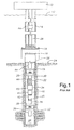
- Figure 1 is a sectional view of a prior art configuration utilising a downhole electric pump assembly to inject high pressure fluid into a formation.
- the prior art configuration of Figure 1 has a surface platform 10 (shown schematically) extending above ocean surface 12.
- Production riser 14 extends downwardly to hydraulically actuated connector 16 which is sealingly connected to wellhead housing 18 in a manner well known to those of ordinary skill in the art.
- Casing 20 extends from wellhead housing 18 to subsurface formation 22 and is cemented in place in ocean floor 24.
- Production tubing 26 extends from surface platform 10 through wellhead housing 18 to downhole packer 28 positioned in casing 20.
- Extension nipple 30 and coupling 32 connect production tubing 26 to downhole electric pump assembly 34.
- Lower extension nipple 36 extends from downhole electric pump assembly 34 through lower downhole packer 38 to that area of the wellbore adjacent subsurface formation 22.
- Downhole electric pump assembly 34 includes electric motor 40, motor seal section 41 and downhole electric pump 42.
- Electrical cable 44 extends from the surface to electric motor 40 in a manner well known to those of ordinary skill in the art.
- a typical sequence of operation has fluid 46 supplied from surface platform 10 through production tubing 26 to downhole electric pump assembly 34 where it is taken into the pump assembly through intake ports 35. Thereafter, downhole electric pump assembly 34 increases the pressure of fluid 46 and then discharges it through lower extension nipple 36 into subsurface formation 22.
- pressurised fluid 46 may be used to cause fracturing of the subsurface formation 22 to increase production capacity or it can be used to urge oil to another area of a field for collection at another well.
- U.S. Patent No. 5,203,682 shows a submersible pump assembly mounted in a container for use at the surface for pressurising fluid.
- the modular pump shown in U.S. Patent No. 5,626,467 discloses a fluid driven by an air motor.
- U.S. Patent No. 5,799,834 shows an adjustable length column pipe for connecting a submersible electric pump in a fuel storage tank to dispenser units.
- the isolation container of the present invention is designed for use with a downhole electric pump or other electrical pump commonly used in oil and gas drilling and production operations.
- an isolation container apparatus for isolating a downhole pump assembly and a fluid pumped therethough from a wellbore therearound, the apparatus comprising:
- the isolation container includes an annular vessel with an axial inlet and outlet bore.
- a downhole electric pump is centrally located within the isolation container.
- the downhole electric pump includes an electric motor positioned above and coupled to a motor seal section, which is then coupled to a centrifugal pump, thereby providing a means of powering the pump.
- a blind coupling is positioned above the electric motor with a tubular member connected thereto and extending through the inlet of the isolation container.
- the tubular member connects to a tubing string supplying fluid from the surface.
- the blind coupling has a plurality of radially disposed ports to allow fluid from the surface to flow into the annulus between the downhole electric pump and the isolation container. This fluid then flows to inlet ports on the downhole electric pump.
- the pressure of the fluid is increased or boosted by the operation of the downhole electric pump and the fluid is discharged through a tubular member, which is sealed in the outlet bore of the isolation container.
- the tubular member extends through a packer positioned below the isolation container and the pressurised fluid is injected into the desired subsurface formation or zone for fracturing or for displacing oil towards an adjacent formation.
- An electrical cable from the surface supplies power to the electric motor and a check valve may be provided on the upper end of the isolation container for releasing entrained air in the isolation container.
- the container effectively isolates the casing well of the well from the harmful effects of the fluid pumped by the pump.
- the isolation container with an downhole electric pump commonly used in oil and gas drilling and production operations to inject a treatment fluid into a subsurface formation.
- the tubing string above the isolation container has a remotely operable valve, such as by wireline, disposed in its bore.
- the tubing string extends above the isolation container typically is 200 to 500 feet (61 to 152 m) in length and is filled with the fluid to be used in the operation.
- the top of tubing string is capped and electrical cable or "E” line as it referred to in the industry is attached to the cap.
- the "E” line is of the type commonly deployed from a wireline truck and typically is 3 ⁇ 4" (19 mm) in diameter. The wireline truck is used to lower the tubing string and isolation container into position.
- a blind coupling is positioned above the electric motor with a tubular member connected thereto and extending through the inlet of the isolation container.
- the blind coupling has a plurality of radially disposed ports to allow the fluid from the tubing string to flow into the annulus between the downhole electric pump and the isolation container when the tubing string valve is opened.
- the fluid then flows to inlet ports on the downhole electric pump.
- the pressure of the fluid is then increased or boosted by the operation of the downhole electric pump.
- the fluid is then discharged through a tubular member, which is sealed in the outlet bore of the isolation container.
- the tubular member extends through a packer positioned below the isolation container and the boosted pressure fluid is injected into the desired subsurface formation or zone for acidising.
- the aforementioned "E" line is extended along the outside of the tubing string and supplies power to the electric motor.
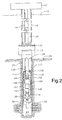
- FIG. 2 a sectional view of an isolation container utilising a downhole electric pump assembly to inject high pressure fluid into a formation is shown.
- the configuration has a surface platform 10 (shown schematically) extending above ocean surface 12.
- Production riser 14 extends downwardly to hydraulically actuated connector 16 which is sealingly connected to wellhead housing 18 in a manner well known to those of ordinary skill in the art.
- Casing 20 extends from wellhead housing 18 to subsurface formation 22 and is cemented in place in ocean floor 24.
- Production tubing 26 extends from surface platform 10 through wellhead housing 18 to isolation container 100 positioned in casing 20.
- Blind coupling 102 is threaded and sealed to production tubing 26.
- Blind coupling 102 connects downhole electric pump assembly 104 within isolation container 100.
- Lower extension nipple 36 extends from downhole electric pump assembly 104 through isolation container 100 and lower downhole packer 38 to subsurface formation 22.
- Downhole electric pump assembly 104 includes electric motor 106, motor seal section 107 and downhole electric pump 108.
- Electrical cable 44 extends from the surface to downhole electric pump assembly 104 in a manner well known to those of ordinary skill in the art.
- Isolation container 100 is designed to isolate the wellbore casing 20 from fluid supplied from the surface including any pressure under which the fluid is delivered to the downhole region of the wellbore.
- Isolation container 100 may include check valve 110 for releasing any air trapped in pressurised fluid 46.
- seal rings 112 and 114 provide sealing around tubing 26 and lower extension nipple 36.
- the isolation container will be typically be constructed of corrosion resistant material to withstand corrosive effects of pumped fluid and will also have sufficient wall thickness to resist any pressure of the fluid as it is delivered from the surface.
- a typical sequence of operation has fluid 46 supplied from surface platform 10 through production tubing 26 and into isolation container 100.
- Blind coupling 102 has a plurality of radially disposed ports 116 therein. Ports 116 provide fluid communication for fluid 46, thereby allowing fluid to flow into annulus 118 between downhole electric pump assembly 104 and isolation container 100. Fluid 46 then flows into inlet ports 120 of downhole electric pump 108 where its pressure is increased or boosted. Pressurised fluid 46 is then discharged through lower extension nipple 36 through packer 38 and into subsurface formation 22. Pressurised fluid 46 may be used to cause fracturing of the subsurface formation 22 and thereby increase production capacity or it can be used to direct oil to another area for collection at another well. In this manner, the isolation container 100 allows fluid 46 to be boosted in pressure downhole without exposing the adjacent formation to pressurised fluid 46.
- Figure 3 is a sectional view of an isolation container utilising a downhole electric pump assembly for the purpose of injecting treatment fluid, such as acid, into a formation.
- the arrangement is used to facilitate the treatment of a formation with fluid without the necessity of having a rig or even a source of coiled tubing at the well site.
- the configuration includes support frame 200 (shown schematically) extending above wellhead 202 and wireline blowout preventer 204 at ground level 206.
- Wireline truck 208 is positioned adjacent support frame 200 with structural and electrical line 210 running through pulley 212 and extending into wellbore 214.
- Casing 216 extends downwardly from wellhead 202 to subsurface formation 218 and is cemented in place with perforations 220 in casing 216 adjacent subsurface formation 218.
- Tubing string 222 is capped at its upper end with wireline cap 224 and the wire line is attached thereto in a manner whereby the weight of the string 222 is supported by the wireline. From the cap 224, wireline extends along tubing string 222 to supply power to the downhole electric pump assembly.
- Tubing string 222 is composed of multiple tubing joints and is typically 200 to 500 feet (61 to 152 m) in length.
- Tubing string 222 extends to valve adapter sub 226 which includes remotely operable valve 228.
- Valve adapter sub 226 extends into isolation container 230 positioned in casing 216.
- Blind coupling 232 is threaded and sealed to valve adapter sub 226 and blind coupling 232 connects downhole electric pump assembly 234 within isolation container 230.
- Lower extension nipple 236 extends from downhole electric pump assembly 234 through isolation container 230 and lower downhole packer 238 to subsurface formation 218.
- Downhole electric pump assembly 234 includes electric motor 240, motor seal section 242 and downhole electric pump 244 as in the first embodiment.
- Electrical cable 210 extends from the surface to 7 downhole electric pump assembly 234 in a manner well known to those of ordinary skill in the art.
- Isolation container 230 is designed to contain the pressure generated by the hydrostatic head of the fluid 246 contained within tubing string 222 and the pressure of fluid 246 and any corrosive effects associated therewith. Seal rings 248 and 250 provide sealing around tubing 26 and lower extension nipple 36.
- fluid 246 is enclosed and run into the wellbore in tubing string 222 where it is held therein by remotely operable valve 228.
- Tubing string 222 connects to valve adapter sub 226 and in turn to blind coupling 232 as previously described.
- Tubing suing 222 and isolation container 230 including downhole electric pump assembly 234 are lowered into casing 216 on electrical cable 210 in a manner well known to those of ordinary skill in the art.
- lower downhole packer 238 is actuated.
- Remotely operable valve 228 is then actuated to allow fluid 246 to flow downwardly to blind coupling 232 that has a plurality of radially disposed ports 252 therein.
- Ports 252 provide fluid communication for fluid 246 to flow into annulus 254 between downhole electric pump assembly 234 and isolation container 230. Fluid 246 then flows into inlet ports 256 of downhole electric pump 244 where its pressure is increased or boosted. Fluid 246 is then discharged through lower extension nipple 236 through packer 238 through perforations 220 and into subsurface formation 218. Thus isolation container 230 in combination with tubing string 222 allows fluid 246 to be boosted in pressure and injected without exposing the casing to fluid 246.
- isolation container for downhole electric pump assemblies for isolating an downhole electric pump assembly and the fluid it pumps from the surrounding wellbore casing thereby ensuring that the surrounding casing is not exposed to the high pressure and/or corrosive fluid.
Landscapes
- Engineering & Computer Science (AREA)
- Mining & Mineral Resources (AREA)
- Geology (AREA)
- Life Sciences & Earth Sciences (AREA)
- Mechanical Engineering (AREA)
- General Engineering & Computer Science (AREA)
- Fluid Mechanics (AREA)
- Environmental & Geological Engineering (AREA)
- General Life Sciences & Earth Sciences (AREA)
- Geochemistry & Mineralogy (AREA)
- Physics & Mathematics (AREA)
- Structures Of Non-Positive Displacement Pumps (AREA)
- Details Of Reciprocating Pumps (AREA)
Abstract
Description
- This invention relates to an isolation container for use with a downhole electric pump and the method of its application.
- The downhole electric pump is of the type used in the oil and gas industry. Such pumps usually are used for pumping oil and gas production to the surface when naturally occurring formation pressure is insufficient to raise the oil and gas to the surface. However, downhole electric pumps are also used in a downhole environment to increase the pressure of pressurised and un-pressurised fluids supplied from the surface. In these instances, the pressurised fluid is injected into the adjacent oil and gas bearing formation to treat or "fracture" the formation. In other applications, a downhole electric pump pressurises fluid for injection into a formation to urge oil in the area of the wellbore in the direction of another nearby well where the oil is more easily produced. In these operations, any number of wells may be used to "chase" the underground oil to the collecting well. Figure 1 is a sectional view of a prior art configuration utilising a downhole electric pump assembly to inject high pressure fluid into a formation. The prior art configuration of Figure 1 has a surface platform 10 (shown schematically) extending above
ocean surface 12.Production riser 14 extends downwardly to hydraulically actuatedconnector 16 which is sealingly connected towellhead housing 18 in a manner well known to those of ordinary skill in the art. Casing 20 extends fromwellhead housing 18 tosubsurface formation 22 and is cemented in place inocean floor 24.Production tubing 26 extends fromsurface platform 10 throughwellhead housing 18 todownhole packer 28 positioned incasing 20. Extension nipple 30 andcoupling 32 connectproduction tubing 26 to downhole electric pump assembly 34.Lower extension nipple 36 extends from downhole electric pump assembly 34 throughlower downhole packer 38 to that area of the wellboreadjacent subsurface formation 22. Downhole electric pump assembly 34 includeselectric motor 40,motor seal section 41 and downholeelectric pump 42.Electrical cable 44 extends from the surface toelectric motor 40 in a manner well known to those of ordinary skill in the art. - A typical sequence of operation has
fluid 46 supplied fromsurface platform 10 throughproduction tubing 26 to downhole electric pump assembly 34 where it is taken into the pump assembly throughintake ports 35. Thereafter, downhole electric pump assembly 34 increases the pressure offluid 46 and then discharges it throughlower extension nipple 36 intosubsurface formation 22. In this manner, pressurisedfluid 46 may be used to cause fracturing of thesubsurface formation 22 to increase production capacity or it can be used to urge oil to another area of a field for collection at another well. - There are problems associated with prior art electric pumps used in a wellbore. As is visible in the apparatus of Figure 1, the fluid for injection into the
formation 22 must first be deposited in an annular area between thepump intake ports 35 and the wellcasing wall 20, subjecting thewell casing 20 to any fluid used in the injection operation. Fluids used in these operations are often corrosive. For example, a fracturing operation can utilise additives like surfactants and acidising fluids. In cases where water is injected into a formation, the water itself, especially sea water, can be corrosive. In those cases where the pressure of a fluid is increased at the well surface and then boosted by the downhole pump, the casing wall is subjected to the pressure of the fluid. Continued exposure of casing wall to the effects of corrosive and high pressure fluids can lead to a collapse of the casing well and ultimate exposure of the wellbore to the surrounding elements. - U.S. Patent No. 5,203,682 shows a submersible pump assembly mounted in a container for use at the surface for pressurising fluid. The modular pump shown in U.S. Patent No. 5,626,467 discloses a fluid driven by an air motor. U.S. Patent No. 5,799,834 shows an adjustable length column pipe for connecting a submersible electric pump in a fuel storage tank to dispenser units.
- The isolation container of the present invention is designed for use with a downhole electric pump or other electrical pump commonly used in oil and gas drilling and production operations.
- In accordance with one aspect of the present invention there is provided an isolation container apparatus for isolating a downhole pump assembly and a fluid pumped therethough from a wellbore therearound, the apparatus comprising:
- an isolation container constructed and arranged to sealingly house the downhole pump assembly;
- a sealed inlet in a wall of the container permitting the passage of a fluid into ah interior of the container; and
- Further aspects and preferred features are set out in claims 2 et seq.
- In preferred embodiments, the isolation container includes an annular vessel with an axial inlet and outlet bore. A downhole electric pump is centrally located within the isolation container. The downhole electric pump includes an electric motor positioned above and coupled to a motor seal section, which is then coupled to a centrifugal pump, thereby providing a means of powering the pump. A blind coupling is positioned above the electric motor with a tubular member connected thereto and extending through the inlet of the isolation container. The tubular member connects to a tubing string supplying fluid from the surface. The blind coupling has a plurality of radially disposed ports to allow fluid from the surface to flow into the annulus between the downhole electric pump and the isolation container. This fluid then flows to inlet ports on the downhole electric pump. The pressure of the fluid is increased or boosted by the operation of the downhole electric pump and the fluid is discharged through a tubular member, which is sealed in the outlet bore of the isolation container. The tubular member extends through a packer positioned below the isolation container and the pressurised fluid is injected into the desired subsurface formation or zone for fracturing or for displacing oil towards an adjacent formation. An electrical cable from the surface supplies power to the electric motor and a check valve may be provided on the upper end of the isolation container for releasing entrained air in the isolation container. The container effectively isolates the casing well of the well from the harmful effects of the fluid pumped by the pump.
- Further preferred embodiments use the isolation container with an downhole electric pump commonly used in oil and gas drilling and production operations to inject a treatment fluid into a subsurface formation. The tubing string above the isolation container has a remotely operable valve, such as by wireline, disposed in its bore. The tubing string extends above the isolation container typically is 200 to 500 feet (61 to 152 m) in length and is filled with the fluid to be used in the operation. The top of tubing string is capped and electrical cable or "E" line as it referred to in the industry is attached to the cap. The "E" line is of the type commonly deployed from a wireline truck and typically is ¾" (19 mm) in diameter. The wireline truck is used to lower the tubing string and isolation container into position. A blind coupling is positioned above the electric motor with a tubular member connected thereto and extending through the inlet of the isolation container. The blind coupling has a plurality of radially disposed ports to allow the fluid from the tubing string to flow into the annulus between the downhole electric pump and the isolation container when the tubing string valve is opened. The fluid then flows to inlet ports on the downhole electric pump. The pressure of the fluid is then increased or boosted by the operation of the downhole electric pump. The fluid is then discharged through a tubular member, which is sealed in the outlet bore of the isolation container. The tubular member extends through a packer positioned below the isolation container and the boosted pressure fluid is injected into the desired subsurface formation or zone for acidising. The aforementioned "E" line is extended along the outside of the tubing string and supplies power to the electric motor.
- Some preferred embodiments of the invention will now be described by way of example only and with reference to the accompanying drawings, in which:
- Figure 1 is a section view of a prior art configuration with downhole packers positioned above and below an downhole electric pump that is used in formation fracturing and injection operations;
- Figure 2 is a section view of an isolation container in accordance with the present invention placed in a well bore with a single downhole packer below allowing isolation of the high pressure fluid to be injected into the subsurface formation; and
- Figure 3 is a section view of the isolation container of the present invention place in a well bore with a tubing string containing fluid above and a single downhole packer below allowing isolation of the casing from the fluid to be injected into the subsurface formation.
- Referring to Figure 2, a sectional view of an isolation container utilising a downhole electric pump assembly to inject high pressure fluid into a formation is shown. Those items which are the same as in the prior art configuration of Figure 1, retain the same numerical designations. The configuration has a surface platform 10 (shown schematically) extending above
ocean surface 12.Production riser 14 extends downwardly to hydraulically actuatedconnector 16 which is sealingly connected towellhead housing 18 in a manner well known to those of ordinary skill in the art.Casing 20 extends fromwellhead housing 18 tosubsurface formation 22 and is cemented in place inocean floor 24.Production tubing 26 extends fromsurface platform 10 throughwellhead housing 18 toisolation container 100 positioned incasing 20.Blind coupling 102 is threaded and sealed toproduction tubing 26.Blind coupling 102 connects downholeelectric pump assembly 104 withinisolation container 100.Lower extension nipple 36 extends from downholeelectric pump assembly 104 throughisolation container 100 and lowerdownhole packer 38 tosubsurface formation 22. - Downhole
electric pump assembly 104 includeselectric motor 106,motor seal section 107 and downholeelectric pump 108.Electrical cable 44 extends from the surface to downholeelectric pump assembly 104 in a manner well known to those of ordinary skill in the art.Isolation container 100 is designed to isolate the wellbore casing 20 from fluid supplied from the surface including any pressure under which the fluid is delivered to the downhole region of the wellbore.Isolation container 100 may includecheck valve 110 for releasing any air trapped in pressurisedfluid 46. Additionally, seal rings 112 and 114 provide sealing aroundtubing 26 andlower extension nipple 36. The isolation container will be typically be constructed of corrosion resistant material to withstand corrosive effects of pumped fluid and will also have sufficient wall thickness to resist any pressure of the fluid as it is delivered from the surface. - A typical sequence of operation has
fluid 46 supplied fromsurface platform 10 throughproduction tubing 26 and intoisolation container 100.Blind coupling 102 has a plurality of radially disposedports 116 therein.Ports 116 provide fluid communication forfluid 46, thereby allowing fluid to flow intoannulus 118 between downholeelectric pump assembly 104 andisolation container 100.Fluid 46 then flows intoinlet ports 120 of downholeelectric pump 108 where its pressure is increased or boosted.Pressurised fluid 46 is then discharged throughlower extension nipple 36 throughpacker 38 and intosubsurface formation 22.Pressurised fluid 46 may be used to cause fracturing of thesubsurface formation 22 and thereby increase production capacity or it can be used to direct oil to another area for collection at another well. In this manner, theisolation container 100 allows fluid 46 to be boosted in pressure downhole without exposing the adjacent formation to pressurisedfluid 46. - Figure 3 is a sectional view of an isolation container utilising a downhole electric pump assembly for the purpose of injecting treatment fluid, such as acid, into a formation. The arrangement is used to facilitate the treatment of a formation with fluid without the necessity of having a rig or even a source of coiled tubing at the well site. The configuration includes support frame 200 (shown schematically) extending above
wellhead 202 andwireline blowout preventer 204 atground level 206.Wireline truck 208 is positionedadjacent support frame 200 with structural andelectrical line 210 running throughpulley 212 and extending intowellbore 214. Casing 216 extends downwardly fromwellhead 202 tosubsurface formation 218 and is cemented in place withperforations 220 incasing 216adjacent subsurface formation 218. -
Tubing string 222 is capped at its upper end withwireline cap 224 and the wire line is attached thereto in a manner whereby the weight of thestring 222 is supported by the wireline. From thecap 224, wireline extends alongtubing string 222 to supply power to the downhole electric pump assembly.Tubing string 222 is composed of multiple tubing joints and is typically 200 to 500 feet (61 to 152 m) in length.Tubing string 222 extends tovalve adapter sub 226 which includes remotelyoperable valve 228.Valve adapter sub 226 extends intoisolation container 230 positioned incasing 216.Blind coupling 232 is threaded and sealed tovalve adapter sub 226 andblind coupling 232 connects downholeelectric pump assembly 234 withinisolation container 230. -
Lower extension nipple 236 extends from downholeelectric pump assembly 234 throughisolation container 230 and lowerdownhole packer 238 tosubsurface formation 218. Downholeelectric pump assembly 234 includeselectric motor 240,motor seal section 242 and downholeelectric pump 244 as in the first embodiment.Electrical cable 210 extends from the surface to 7 downholeelectric pump assembly 234 in a manner well known to those of ordinary skill in the art.Isolation container 230 is designed to contain the pressure generated by the hydrostatic head of the fluid 246 contained withintubing string 222 and the pressure offluid 246 and any corrosive effects associated therewith. Seal rings 248 and 250 provide sealing aroundtubing 26 andlower extension nipple 36. - In a typical sequence of operation,
fluid 246 is enclosed and run into the wellbore intubing string 222 where it is held therein by remotelyoperable valve 228.Tubing string 222 connects tovalve adapter sub 226 and in turn toblind coupling 232 as previously described. Tubing suing 222 andisolation container 230 including downholeelectric pump assembly 234 are lowered intocasing 216 onelectrical cable 210 in a manner well known to those of ordinary skill in the art. At the appropriate depth, lowerdownhole packer 238 is actuated. Remotelyoperable valve 228 is then actuated to allow fluid 246 to flow downwardly toblind coupling 232 that has a plurality of radially disposedports 252 therein.Ports 252 provide fluid communication forfluid 246 to flow intoannulus 254 between downholeelectric pump assembly 234 andisolation container 230.Fluid 246 then flows intoinlet ports 256 of downholeelectric pump 244 where its pressure is increased or boosted.Fluid 246 is then discharged throughlower extension nipple 236 throughpacker 238 throughperforations 220 and intosubsurface formation 218. Thusisolation container 230 in combination withtubing string 222 allows fluid 246 to be boosted in pressure and injected without exposing the casing tofluid 246. - The construction of the isolation container for downhole electric pump assemblies will be readily understood from the foregoing description and it will be seen that there is provided an isolation container for downhole electric pump assemblies for isolating an downhole electric pump assembly and the fluid it pumps from the surrounding wellbore casing thereby ensuring that the surrounding casing is not exposed to the high pressure and/or corrosive fluid. Furthermore, while the invention has been shown and described with respect to certain preferred embodiments, it is obvious that equivalent alterations and modifications will occur to others skilled in the art upon the reading and understanding of the specification. The present invention includes all such equivalent alterations and modifications, and is limited only by the scope of the appended claims.
a sealed outlet in the wall of the container permitting the passage of a pumped fluid from the interior of the container.
Claims (27)
- An isolation container apparatus for isolating a downhole pump assembly and a fluid pumped therethough from a wellbore therearound, the apparatus comprising:an isolation container constructed and arranged to sealingly house the downhole pump assembly;a sealed inlet in a wall of the container permitting the passage of a fluid into an interior of the container; anda sealed outlet in the wall of the container permitting the passage of a pumped fluid from the interior of the container.
- An apparatus as claimed in claim 1, wherein the pressure of the fluid at the outlet is higher than the pressure of the fluid at the inlet.
- An apparatus as claimed in claim 1 or 2, including a tubular transporting the fluid through the sealed inlet.
- An apparatus as claimed in claim 1, 2 or 3, including a tubular transporting the fluid through the sealed outlet.
- An apparatus as claimed in claim 4, further including a packing member to seal the wellbore around the tubular transporting the fluid from the sealed outlet.
- An apparatus as claimed in any preceding claim, wherein the pump assembly includes a pump and a motor.
- An apparatus as claimed in claim 6, further including a fluid path around the motor.
- An apparatus as claimed in any preceding claim, wherein the pump is an electric pump and includes a conductor supplying electrical power thereto from the well surface.
- An apparatus as claimed in any preceding claim, wherein the isolation container is a pressure vessel and pressure therein is isolated form the wellbore therearound.
- An apparatus as claimed in any preceding claim, further including a check valve positioned on the isolation container for discharging gas from the isolation container.
- An isolation container apparatus as claimed in any preceding claim, wherein the downhole pump assembly is arranged to boost pressure of an injection fluid for injection into a subsurface formation.
- An isolation container apparatus as claimed in any preceding claim, wherein:the isolation contained is constructed and arranged to sealingly house the downhole pump assembly when the downhole pump assembly is oriented to pump fluids towards an earth formation;the sealed inlet is constructed and arranged to receive a tubular string;an upper coupling having at least one outlet port therein is arranged to connect the tubular string and an upper end of the pump assembly;the sealed outlet is arranged to receive a lower tubular member;a lower coupling is arranged to connect a lower end of the pump assembly and the lower tubular member, the lower coupling having at least one inlet port therein through which fluids are delivered to the pump assembly; anda fluid path is formed around the pump assembly permitting fluid to flow from the at least one outlet port into the at least one inlet port.
- An apparatus for injecting formation treatment fluid into a formation while isolating the fluid from a cased wellbore therearound, the apparatus comprising:a tubular string for containing a predetermined amount of fluid in a portion thereof;an isolation container as claimed in any preceding claim at a lower end of the string, the isolation container sealably receiving the tubular string in a first end;a valve separating the string from the container, the valve remotely operable to expose the fluid to the container; andan exit tubular extending from the sealed outlet of the isolation container for transporting pressurised fluid leaving the pump assembly.
- An apparatus as claimed in claim 13, further comprising a conveyance member attached to an upper end of the tubing string for lowering or raising the tubing string.
- An apparatus as claimed in claim 13 or 14, wherein the valve is included in a valve assembly, the valve assembly further comprising a valve adapter and an upper coupling with at least one port formed therein.
- An apparatus as claimed in claim 13, 14 or 15, further including a packer disposed on the tubular string below the isolation container, the packer constructed and arranged to seal an annular area between the exit tubular and the wellbore therearound.
- A method of increasing pressure of a fluid in a wellbore while isolating the fluid from wellbore casing, the method comprising:providing fluid from a surface of a well to a predetermined location in the wellbore therebelow;providing a path for the fluid into a sealed container in the wellbore, the container housing a pump and a motor;using the pump to increase the pressure of the fluid;providing an exit path for the pressurised fluid from the container into the wellbore therebelow; andproviding a path from the wellbore to a formation therearound.
- A method as claimed in claim 17, wherein the pump assembly is an electric pump assembly, the method further comprising:supplying electrical power to the downhole electric pump assembly;operating the downhole electric pump assembly to boost the pressure of the fluid;conducting pressurised fluid through a packer disposed in the wellbore below the pump assembly and container; andinjecting the pressurised fluid into a subsurface formation below said packer.
- A method as claimed in claim 17 or 18, further including providing a fluid bypass around the motor.
- A method for injecting a fluid into a formation while isolating the fluid from a wellbore, the method comprising:installing an isolation jacket having a tubular string and a connected pump assembly therein on a conveyance member;containing a predetermined amount of fluid above the isolation jacket;lowering the conveyance member into the wellbore thereby locating the isolation jacket, the pump assembly and the predetermined amount of fluid;isolating a wellbore annulus formed between the wellbore and the isolation jacket from the wellbore below the isolation jacket;opening a remotely operable valve on the tubular string, thereby releasing the fluid into the jacket; andactuating the pump assembly, thereby injecting the fluid into the formation.
- A method as claimed in claim 20, wherein the conveyance member is a tubular string.
- A method as claimed in claim 20,wherein the conveyance member is wire line.
- A method as claimed in claim 20, wherein the conveyance member is coiled tubing.
- A method as claimed in claim 20, wherein the conveyance member is slick line.
- A method as claimed in any of claims 20 to 24, further comprising releasing accumulated gas from the isolation jacket through a valve member disposed proximate an upper end of the isolation jacket.
- A method as claimed in any of claims 20 to 25, wherein the fluid is an acidizing fluid for treating the formation.
- A method as claimed in any of claims 20 to 25, wherein the fluid is a formation fracturing solution for fracturing the formation.
Applications Claiming Priority (2)
| Application Number | Priority Date | Filing Date | Title |
|---|---|---|---|
| US09/608,077 US6568475B1 (en) | 2000-06-30 | 2000-06-30 | Isolation container for a downhole electric pump |
| EP01940832A EP1295035B1 (en) | 2000-06-30 | 2001-06-22 | Isolation container for a downhole electric pump |
Related Parent Applications (1)
| Application Number | Title | Priority Date | Filing Date |
|---|---|---|---|
| EP01940832A Division EP1295035B1 (en) | 2000-06-30 | 2001-06-22 | Isolation container for a downhole electric pump |
Publications (1)
| Publication Number | Publication Date |
|---|---|
| EP1614898A1 true EP1614898A1 (en) | 2006-01-11 |
Family
ID=24434936
Family Applications (2)
| Application Number | Title | Priority Date | Filing Date |
|---|---|---|---|
| EP05270046A Withdrawn EP1614898A1 (en) | 2000-06-30 | 2001-06-22 | Isolation container for a downhole electric pump |
| EP01940832A Expired - Lifetime EP1295035B1 (en) | 2000-06-30 | 2001-06-22 | Isolation container for a downhole electric pump |
Family Applications After (1)
| Application Number | Title | Priority Date | Filing Date |
|---|---|---|---|
| EP01940832A Expired - Lifetime EP1295035B1 (en) | 2000-06-30 | 2001-06-22 | Isolation container for a downhole electric pump |
Country Status (6)
| Country | Link |
|---|---|
| US (2) | US6568475B1 (en) |
| EP (2) | EP1614898A1 (en) |
| AU (1) | AU2001274325A1 (en) |
| CA (1) | CA2412144C (en) |
| DE (1) | DE60118735D1 (en) |
| WO (1) | WO2002002947A1 (en) |
Families Citing this family (31)
| Publication number | Priority date | Publication date | Assignee | Title |
|---|---|---|---|---|
| US6568475B1 (en) * | 2000-06-30 | 2003-05-27 | Weatherford/Lamb, Inc. | Isolation container for a downhole electric pump |
| US7051815B2 (en) * | 2002-08-22 | 2006-05-30 | Baker Hughes Incorporated | Well pump capsule |
| US7069985B2 (en) * | 2003-06-17 | 2006-07-04 | Wood Group Esp, Inc. | Leakage resistant shroud hanger |
| US8636478B2 (en) * | 2006-01-11 | 2014-01-28 | Besst, Inc. | Sensor assembly for determining fluid properties in a subsurface well |
| US20080078560A1 (en) * | 2006-10-02 | 2008-04-03 | Kevin Hall | Motor seal |
| KR100770051B1 (en) * | 2006-12-26 | 2007-10-26 | 한국원자력연구원 | Groundwater Collection Device |
| US8261834B2 (en) | 2007-04-30 | 2012-09-11 | Schlumberger Technology Corporation | Well treatment using electric submersible pumping system |
| US7673684B2 (en) * | 2008-04-24 | 2010-03-09 | Cobb Delwin E | ESP/separator assembly and method |
| US8240387B2 (en) * | 2008-11-11 | 2012-08-14 | Wild Well Control, Inc. | Casing annulus tester for diagnostics and testing of a wellbore |
| US9103199B2 (en) * | 2009-12-31 | 2015-08-11 | Baker Hughes Incorporated | Apparatus and method for pumping a fluid and an additive from a downhole location into a formation or to another location |
| RU2484307C1 (en) * | 2011-12-23 | 2013-06-10 | Геннадий Михайлович Моргунов | Submersible pumping unit |
| US8689878B2 (en) | 2012-01-03 | 2014-04-08 | Baker Hughes Incorporated | Junk basket with self clean assembly and methods of using same |
| US9080401B2 (en) | 2012-04-25 | 2015-07-14 | Baker Hughes Incorporated | Fluid driven pump for removing debris from a wellbore and methods of using same |
| US8973662B2 (en) | 2012-06-21 | 2015-03-10 | Baker Hughes Incorporated | Downhole debris removal tool capable of providing a hydraulic barrier and methods of using same |
| US9045979B2 (en) | 2012-12-11 | 2015-06-02 | Delwin E. Cobb | Downhole gas separator and method |
| CN103047127B (en) * | 2012-12-18 | 2016-01-20 | 安塞凯源工贸有限责任公司 | A kind of exhaust pump that can solve high liquid level (HLL) exhaust problem |
| BR112015016041A2 (en) * | 2013-01-02 | 2017-11-21 | Schlumberger Technology Bv | system for injecting fluids from a source zone to a well-associated wellbore target zone, silo structure for containing a submersible electric discharge pump in oil well applications, and method for injecting fluids from a wellbore a source zone for a well target zone associated with a well |
| US9228414B2 (en) | 2013-06-07 | 2016-01-05 | Baker Hughes Incorporated | Junk basket with self clean assembly and methods of using same |
| US9416626B2 (en) | 2013-06-21 | 2016-08-16 | Baker Hughes Incorporated | Downhole debris removal tool and methods of using same |
| MX2017004315A (en) * | 2014-10-01 | 2018-01-17 | Geo Innova Consultoria E Participacoes Ltda | Well completion system and method, drilled well. |
| US10119383B2 (en) * | 2015-05-11 | 2018-11-06 | Ngsip, Llc | Down-hole gas and solids separation system and method |
| RU2614426C1 (en) * | 2015-12-31 | 2017-03-28 | Публичное акционерное общество "Татнефть" имени В.Д. Шашина | Pump unit for products lift along the casing string |
| RU167799U1 (en) * | 2016-04-12 | 2017-01-10 | Самуил Григорьевич Бриллиант | STEPS DIFFERENTIAL SUBMERSIBLE ELECTRIC PUMP UNIT FOR INSTALLATION AND SEPARATE OPERATION OF MULTIPLE LAYERS IN HIGH-DEEP DEEP AND ULTRA DEEP SHELLS |
| CN107780912B (en) * | 2016-08-31 | 2020-08-11 | 中国石油天然气股份有限公司 | Cased well fracturing fluid drainage method and system |
| US10865627B2 (en) * | 2017-02-01 | 2020-12-15 | Saudi Arabian Oil Company | Shrouded electrical submersible pump |
| US20170254333A1 (en) * | 2017-05-19 | 2017-09-07 | LT Lighting (Taiwan) Corp. | Multi-pump system with system check |
| RU184655U1 (en) * | 2018-09-05 | 2018-11-02 | Общество с ограниченной ответственностью "ЛУКОЙЛ-ПЕРМЬ" | LIQUID INJECTION INSTALLATION |
| RU195561U1 (en) * | 2019-06-27 | 2020-01-31 | Пепеляева Валентина Борисовна | LIQUID INJECTION INSTALLATION |
| RU203404U1 (en) * | 2020-11-23 | 2021-04-02 | Общество с ограниченной ответственностью «АЛНАС» | Submersible plant with a vane pump and a gas separator for the production of formation fluid with a high content of gas and mechanical impurities |
| US12215579B1 (en) * | 2023-09-28 | 2025-02-04 | Saudi Arabian Oil Company | Well initiation service system with packer control system |
| US12359532B2 (en) * | 2023-11-30 | 2025-07-15 | Halliburton Energy Services, Inc. | Electrically operated low power completion control system |
Citations (8)
| Publication number | Priority date | Publication date | Assignee | Title |
|---|---|---|---|---|
| US4662831A (en) * | 1984-03-05 | 1987-05-05 | Bennett John D | Apparatus for fracturing earth formations while pumping formation fluids |
| US4696343A (en) * | 1986-05-23 | 1987-09-29 | S.I.E., Inc. | Wireline dump bailer |
| US5220962A (en) * | 1991-09-24 | 1993-06-22 | Schlumberger Technology Corporation | Pump apparatus for pumping well fluids from a wellbore having low formation pressure |
| US5269180A (en) * | 1991-09-17 | 1993-12-14 | Schlumberger Technology Corp. | Borehole tool, procedures, and interpretation for making permeability measurements of subsurface formations |
| US5517854A (en) * | 1992-06-09 | 1996-05-21 | Schlumberger Technology Corporation | Methods and apparatus for borehole measurement of formation stress |
| US5734209A (en) * | 1990-01-10 | 1998-03-31 | Uniflo Oilcorp, Ltd. | Linear electric motor and method of using and constructing same |
| US5813469A (en) * | 1997-03-12 | 1998-09-29 | Texaco Inc. | Coupled downhole pump for simultaneous injection and production in an oil wheel |
| US6079491A (en) * | 1997-08-22 | 2000-06-27 | Texaco Inc. | Dual injection and lifting system using a rod driven progressive cavity pump and an electrical submersible progressive cavity pump |
Family Cites Families (16)
| Publication number | Priority date | Publication date | Assignee | Title |
|---|---|---|---|---|
| US2748719A (en) * | 1953-10-07 | 1956-06-05 | Agate Corp | Gas separators for well pumps |
| US3432992A (en) | 1966-10-14 | 1969-03-18 | Moretrench Corp | Method and apparatus for removing dispersed liquids from the ground |
| US4009756A (en) * | 1975-09-24 | 1977-03-01 | Trw, Incorporated | Method and apparatus for flooding of oil-bearing formations by downward inter-zone pumping |
| US4187912A (en) * | 1977-11-17 | 1980-02-12 | Cramer Robert L | Method and apparatus for pumping fluids from bore holes |
| US4440221A (en) * | 1980-09-15 | 1984-04-03 | Otis Engineering Corporation | Submergible pump installation |
| US4537257A (en) * | 1984-03-16 | 1985-08-27 | Shell Oil Company | Submersible pump |
| US5176164A (en) * | 1989-12-27 | 1993-01-05 | Otis Engineering Corporation | Flow control valve system |
| US5271725A (en) * | 1990-10-18 | 1993-12-21 | Oryx Energy Company | System for pumping fluids from horizontal wells |
| US5133407A (en) * | 1991-05-24 | 1992-07-28 | Marathon Oil Company | Fluid injection and production apparatus and method |
| US5188172A (en) * | 1991-08-30 | 1993-02-23 | Atlantic Richfield Company | Automatic downhole well shut-in control valve |
| US5203682A (en) | 1991-09-04 | 1993-04-20 | Baker Hughes Incorporated | Inclined pressure boost pump |
| WO1997008459A1 (en) * | 1995-08-30 | 1997-03-06 | Baker Hughes Incorporated | An improved electrical submersible pump and methods for enhanced utilization of electrical submersible pumps in the completion and production of wellbores |
| US5626467A (en) | 1996-04-04 | 1997-05-06 | Teledyne Industries, Inc. | Modular pump |
| US5799834A (en) | 1996-10-21 | 1998-09-01 | Marley Pump | Telescoping column pipe assembly for fuel dispensing pumping systems |
| US5779434A (en) | 1997-02-06 | 1998-07-14 | Baker Hughes Incorporated | Pump mounted thrust bearing |
| US6568475B1 (en) * | 2000-06-30 | 2003-05-27 | Weatherford/Lamb, Inc. | Isolation container for a downhole electric pump |
-
2000
- 2000-06-30 US US09/608,077 patent/US6568475B1/en not_active Expired - Fee Related
-
2001
- 2001-06-22 DE DE60118735T patent/DE60118735D1/en not_active Expired - Lifetime
- 2001-06-22 AU AU2001274325A patent/AU2001274325A1/en not_active Abandoned
- 2001-06-22 EP EP05270046A patent/EP1614898A1/en not_active Withdrawn
- 2001-06-22 CA CA002412144A patent/CA2412144C/en not_active Expired - Fee Related
- 2001-06-22 WO PCT/GB2001/002789 patent/WO2002002947A1/en not_active Ceased
- 2001-06-22 EP EP01940832A patent/EP1295035B1/en not_active Expired - Lifetime
-
2003
- 2003-04-16 US US10/414,994 patent/US6962204B2/en not_active Expired - Lifetime
Patent Citations (8)
| Publication number | Priority date | Publication date | Assignee | Title |
|---|---|---|---|---|
| US4662831A (en) * | 1984-03-05 | 1987-05-05 | Bennett John D | Apparatus for fracturing earth formations while pumping formation fluids |
| US4696343A (en) * | 1986-05-23 | 1987-09-29 | S.I.E., Inc. | Wireline dump bailer |
| US5734209A (en) * | 1990-01-10 | 1998-03-31 | Uniflo Oilcorp, Ltd. | Linear electric motor and method of using and constructing same |
| US5269180A (en) * | 1991-09-17 | 1993-12-14 | Schlumberger Technology Corp. | Borehole tool, procedures, and interpretation for making permeability measurements of subsurface formations |
| US5220962A (en) * | 1991-09-24 | 1993-06-22 | Schlumberger Technology Corporation | Pump apparatus for pumping well fluids from a wellbore having low formation pressure |
| US5517854A (en) * | 1992-06-09 | 1996-05-21 | Schlumberger Technology Corporation | Methods and apparatus for borehole measurement of formation stress |
| US5813469A (en) * | 1997-03-12 | 1998-09-29 | Texaco Inc. | Coupled downhole pump for simultaneous injection and production in an oil wheel |
| US6079491A (en) * | 1997-08-22 | 2000-06-27 | Texaco Inc. | Dual injection and lifting system using a rod driven progressive cavity pump and an electrical submersible progressive cavity pump |
Also Published As
| Publication number | Publication date |
|---|---|
| AU2001274325A1 (en) | 2002-01-14 |
| DE60118735D1 (en) | 2006-05-24 |
| EP1295035B1 (en) | 2006-04-12 |
| CA2412144C (en) | 2007-12-18 |
| WO2002002947A1 (en) | 2002-01-10 |
| EP1295035A1 (en) | 2003-03-26 |
| US20030192697A1 (en) | 2003-10-16 |
| CA2412144A1 (en) | 2002-01-10 |
| US6962204B2 (en) | 2005-11-08 |
| US6568475B1 (en) | 2003-05-27 |
Similar Documents
| Publication | Publication Date | Title |
|---|---|---|
| EP1295035B1 (en) | Isolation container for a downhole electric pump | |
| AU2004203372B2 (en) | ROV retrievable sea floor pump | |
| US9909400B2 (en) | Gas separator assembly for generating artificial sump inside well casing | |
| US8316938B2 (en) | Subterranean water production, transfer and injection method and apparatus | |
| CA2531364C (en) | Method of deploying and powering an electrically driven device in a well | |
| US6092600A (en) | Dual injection and lifting system using a rod driven progressive cavity pump and an electrical submersible pump and associate a method | |
| US4266607A (en) | Method for protecting a carbon dioxide production well from corrosion | |
| GB2194572A (en) | Downhole separation of fluids in oil wells | |
| EP2236739A2 (en) | Well unloading package | |
| CN110234836B (en) | Covered ESP | |
| WO2005100744A1 (en) | Apparatus and method for dewatering low pressure gradient gas wells | |
| GB2477909A (en) | Coiled Tubing Deployed ESP | |
| AU2009256454B2 (en) | Offshore drilling and production systems and methods | |
| US3833060A (en) | Well completion and pumping system | |
| US7836955B2 (en) | Wireline bailing system for removing large volumes of liquid from a borehole | |
| US20180073314A1 (en) | Mud lift drilling system using ejector assembly in mud return line | |
| US12168914B2 (en) | Systems and methods of production tubing chemical injection | |
| RU2726704C1 (en) | Flexible pipes with double walls with downhole pump driven by flow | |
| WO2010016767A2 (en) | Subsurface reservoir drainage system | |
| RU2730152C1 (en) | Device for reagent delivery into well | |
| US7836977B2 (en) | Method of drilling a well at or under balance using a electrical submersible pump |
Legal Events
| Date | Code | Title | Description |
|---|---|---|---|
| PUAI | Public reference made under article 153(3) epc to a published international application that has entered the european phase |
Free format text: ORIGINAL CODE: 0009012 |
|
| 17P | Request for examination filed |
Effective date: 20050907 |
|
| AC | Divisional application: reference to earlier application |
Ref document number: 1295035 Country of ref document: EP Kind code of ref document: P |
|
| AK | Designated contracting states |
Kind code of ref document: A1 Designated state(s): AT BE BG CH CY CZ DE DK EE ES FI FR GB GR HU IE IS IT LI LT LU LV MC NL PL PT RO SE SI SK TR |
|
| AX | Request for extension of the european patent |
Extension state: AL BA HR MK YU |
|
| RIN1 | Information on inventor provided before grant (corrected) |
Inventor name: GRUBB, WILLIAM, A Inventor name: HOFFMANN, COREY, E. Inventor name: HAUGEN, DAVID, MICHAEL |
|
| AKX | Designation fees paid |
Designated state(s): DE FR GB NL |
|
| 17Q | First examination report despatched |
Effective date: 20060901 |
|
| 17Q | First examination report despatched |
Effective date: 20060901 |
|
| STAA | Information on the status of an ep patent application or granted ep patent |
Free format text: STATUS: THE APPLICATION IS DEEMED TO BE WITHDRAWN |
|
| 18D | Application deemed to be withdrawn |
Effective date: 20110104 |