EP1614883A1 - Start controller and start control method of engine - Google Patents
Start controller and start control method of engine Download PDFInfo
- Publication number
- EP1614883A1 EP1614883A1 EP04725835A EP04725835A EP1614883A1 EP 1614883 A1 EP1614883 A1 EP 1614883A1 EP 04725835 A EP04725835 A EP 04725835A EP 04725835 A EP04725835 A EP 04725835A EP 1614883 A1 EP1614883 A1 EP 1614883A1
- Authority
- EP
- European Patent Office
- Prior art keywords
- pumping
- engine
- generator
- light
- starter
- Prior art date
- Legal status (The legal status is an assumption and is not a legal conclusion. Google has not performed a legal analysis and makes no representation as to the accuracy of the status listed.)
- Withdrawn
Links
Images


Classifications
-
- F—MECHANICAL ENGINEERING; LIGHTING; HEATING; WEAPONS; BLASTING
- F02—COMBUSTION ENGINES; HOT-GAS OR COMBUSTION-PRODUCT ENGINE PLANTS
- F02D—CONTROLLING COMBUSTION ENGINES
- F02D41/00—Electrical control of supply of combustible mixture or its constituents
- F02D41/009—Electrical control of supply of combustible mixture or its constituents using means for generating position or synchronisation signals
-
- F—MECHANICAL ENGINEERING; LIGHTING; HEATING; WEAPONS; BLASTING
- F02—COMBUSTION ENGINES; HOT-GAS OR COMBUSTION-PRODUCT ENGINE PLANTS
- F02D—CONTROLLING COMBUSTION ENGINES
- F02D41/00—Electrical control of supply of combustible mixture or its constituents
- F02D41/02—Circuit arrangements for generating control signals
- F02D41/04—Introducing corrections for particular operating conditions
- F02D41/06—Introducing corrections for particular operating conditions for engine starting or warming up
- F02D41/062—Introducing corrections for particular operating conditions for engine starting or warming up for starting
-
- F—MECHANICAL ENGINEERING; LIGHTING; HEATING; WEAPONS; BLASTING
- F02—COMBUSTION ENGINES; HOT-GAS OR COMBUSTION-PRODUCT ENGINE PLANTS
- F02D—CONTROLLING COMBUSTION ENGINES
- F02D41/00—Electrical control of supply of combustible mixture or its constituents
- F02D41/02—Circuit arrangements for generating control signals
- F02D41/04—Introducing corrections for particular operating conditions
- F02D41/06—Introducing corrections for particular operating conditions for engine starting or warming up
- F02D41/062—Introducing corrections for particular operating conditions for engine starting or warming up for starting
- F02D41/064—Introducing corrections for particular operating conditions for engine starting or warming up for starting at cold start
-
- F—MECHANICAL ENGINEERING; LIGHTING; HEATING; WEAPONS; BLASTING
- F02—COMBUSTION ENGINES; HOT-GAS OR COMBUSTION-PRODUCT ENGINE PLANTS
- F02P—IGNITION, OTHER THAN COMPRESSION IGNITION, FOR INTERNAL-COMBUSTION ENGINES; TESTING OF IGNITION TIMING IN COMPRESSION-IGNITION ENGINES
- F02P7/00—Arrangements of distributors, circuit-makers or -breakers, e.g. of distributor and circuit-breaker combinations or pick-up devices
- F02P7/06—Arrangements of distributors, circuit-makers or -breakers, e.g. of distributor and circuit-breaker combinations or pick-up devices of circuit-makers or -breakers, or pick-up devices adapted to sense particular points of the timing cycle
Definitions
- the present invention relates to an engine start control device and a start control method.
- Basic application of the present application is Japanese Patent Application No. 2003-107795, the contents of which are incorporated herein by reference.
- battery-less fuel injectors for multiple cylinder internal combustion engines which avoid excess load on a generator when the engine starts, are known (for example, refer to Japanese Unexamined Patent Application, First Publication No. 2002-106397).
- a recoil starter or a kick starter in the case where it is not clear from which cylinder a crank pulse signal output from a signal generator derives, fuel is injected to each of the cylinders in a predetermined order each time a reference pulse signal is generated.
- the present invention has an object of providing an engine start control device and a start control method, that can improve startability.
- the present invention employs the following means.
- an engine start control device of the present invention is a engine start control device capable of starting upon receiving generated power from a generator which is driven by a starter, and includes a fuel injection timing setting device which makes a power generation waveform of the generator correspond to a crank pulse signal, and outputs a fuel injection signal to an injector for injecting fuel to the engine in conformance with a crank pulse signal for when a voltage of the generated power reaches a peak value after a starting operation of the starter.
- An engine start control device of the present invention is an engine start control device capable of starting upon receiving power generated from a generator which is driven by a starter, including: an offset time measuring device which measures an offset time of a peak timing of a voltage generated by a generator with respect to a crank pulse signal, immediately after a starting operation of the starter; and a fuel injection timing setting device which outputs a fuel injection signal to an injector for injecting fuel to the engine, after the offset time has elapsed after the crank pulse signal has been output.
- the offset time which is the time difference between the crank pulse signal and the peak timing of the generated voltage
- the offset measuring device is adjusted by adjustment by the fuel injection timing setting device, when the offset time has elapsed after the crank pulse signal has been output (that is, when the generated voltage reaches a peak), it is possible to inject fuel from the injector. Therefore, it is possible to start the engine in a short time after the starting operation, and at a timing where the supply voltage to the injector reaches a sufficient level.
- a start control method for an engine of the present invention is a start control method for an engine capable of starting upon receiving generated power from a generator which is driven by a starter, including injecting fuel from an injector for injecting fuel to the engine, in conformance with a peak timing of a voltage generated by the generator.
- FIG. 1 is a system configuration diagram for an outboard motor according to the present embodiment.
- An engine (not shown in the figure) of an outboard motor 1 has a fuel pump (P) 3 which is driven via an ECU 2.
- Fuel supplied by the fuel pump 3 is injected by injectors (INJ #1 to 4) 4, ignited by an igniter by energizing an ignition (IG) coil 5, and burned in the cylinders.
- injectors IJ #1 to 4
- IG ignition
- the igniter ignites at an optimum crank angle for each cylinder, based on a crank pulse signal.
- Power is supplied from the battery 8 to the injector 4 in conformance with the ignition timing, to give fuel injection by the injector 4.
- the ECU 2 performs control of a PTC heater 18 for idle control, and open and close control of a relay 7 provided in an accessory circuit 6 for an accessory (ACC) 19 such as a lamp or the like.
- the ECU 2 includes: a CPU, being a central processing unit for performing a range of calculation processing; a RAM (Random Access Memory) used for storing data partway through the calculations by the CPU; a ROM (Read Only Memory) for storing programs that the CPU executes, tables, maps and the like; and an EEP-ROM (Electronically Erasable and Programmable Read Only Memory) for storing backup data and the like.
- a CPU being a central processing unit for performing a range of calculation processing
- a RAM Random Access Memory
- ROM Read Only Memory
- EEP-ROM Electrically Erasable and Programmable Read Only Memory
- a crank angle (CRK) sensor To the ECU 2A is input signals from; a crank angle (CRK) sensor, a throttle opening (TH) sensor, a MAP sensor for detecting the inlet negative pressure of the engine, a water temperature sensor for detecting the temperature of engine cooling water, an inlet temperature sensor, an overheat sensor, an engine cooling oil pressure switch, a stop switch for emergency stop, and an engine speed (NE) sensor.
- a crank angle (CRK) sensor e.g., a throttle opening (TH) sensor
- a MAP sensor for detecting the inlet negative pressure of the engine
- a water temperature sensor for detecting the temperature of engine cooling water
- an inlet temperature sensor detecting the temperature of engine cooling water
- an overheat sensor detecting the temperature of engine cooling water
- an overheat sensor detecting the temperature of engine cooling water
- an engine cooling oil pressure switch e.g., a stop switch for emergency stop
- NE engine speed
- Reference symbol 13 denotes an electrical generator (ACG).
- the electrical generator 13 generates electricity at the time of engine drive, and charges the battery (BAT) 8 of the power circuit 9 via a rectifier (REC) 14, and a regulator (REG) 15 for regulating the voltage.
- the electrical generator 13 also generates electricity in the case of a starting operation by a manual recoil starter 16, and generates starting power for the ECU 2 when the battery capacity is low, which is described later, driving power to the fuel pump (P) 3, and the like.
- the recoil starter 16 is a starter which starts the engine by a starter rope being pulled.
- Reference symbol 17 denotes a main switch of the power circuit 9.
- This flow chart shows the processing of the ECU 2 for in the case where starting is performed using the recoil starter 16, in a situation where the battery residual capacity has dropped, or it is cold, so that the necessary voltage cannot be obtained from the battery 8 (when the battery capacity is low).
- step S1 offset time measuring device
- a three-phase, 18 electrode type is used, and detecting sections are provided in the flywheel every 20 degrees corresponding to this. That is, when the generator 13 is driven by a starting operation of the recoil starter 16 in a situation in which power cannot be obtained from the battery 8, the generated output voltage from the generator 13 fluctuates widely as shown in FIG. 3. At this time, by matching the cycle of the crank pulse signal with the cycle (power generation wave form) of the voltage generated by the generator 13, it is possible to understand the cycle of the voltage generated by the generator 13, more specifically, the timing at which the generated voltage reaches a peak, with reference to the cycle of the crank pulse signal.
- the time from a rising point CPn (to be specific, the fourth rising point CP4 (located at 60 degrees)) to the next peak VPm (to be specific, VP5, being the fifth peak) of the generated voltage is measured as an offset time To.
- the ECU 2 makes a computation immediately after the engine starts, based on an input signal from the crank angle sensor and an input signal from the regulator.
- n and m 1, 2, 3, 4 (positive integers).
- step S2 it is determined whether or not the rising point CP5 (located at 80 degrees) of the next crank pulse signal is reached. In the case where the determination result is "NO”, the flow proceeds again to step S2, while in the case where the determination result is "YES”, the flow proceeds to step S3.
- step S3 fuel injection timing setting device
- a countdown timer is set to T0, and the flow proceeds to step S4.
- step S4 fuel injection timing setting device
- step S4 fuel injection timing setting device
- the present embodiment it is possible to measure the time difference between a crank pulse signal and a peak of the generated voltage, and inject fuel from the injector 4 when the voltage generated by the generator 13 reaches a peak, after the crank pulse signal has been output. Therefore, it is possible to start the engine in a short time after the starting operation, and at the time that the supply voltage to the injector 4 reaches a sufficient level.
- the present invention is not limited in the above-described embodiment.
- an outboard motor 1 incorporating a recoil starter 16 is described as an example.
- the invention can also be used for a start control device of a three-wheel, or four-wheel, dune buggy incorporating a kick starter.
- the example is given of a case in which a battery 8 and a recoil starter 16 are used together.
- the invention can also be applied to a battery-less situation.
- an engine start control device of the present invention is realized in which the procedures that are executed in the engine start control device are stored in a computer readable recording medium, and a program stored in this recording medium is read by a computer system for execution.
- the computer system mentioned here includes an OS (Operating System), and hardware such as peripheral equipment and the like.
- “computer system” also includes a website provider environment (or display environment).
- “computer readable recording medium” means a portable medium such as a flexible disc, optical magnetic disc, ROM, CD-ROM, or the like, and memory storage such as a hard disc or the like, built into a computer system.
- “computer readable recording medium” also includes a system where the program is transmitted via a network such as the Internet or the like, or a communication circuit such as a telephone line, or the like, and in which a program is stored temporarily in a volatile memory (RAM) in a computer system, being a client.
- RAM volatile memory
- transmission medium means a medium having a function of transmitting information, such as a network (communication network) such as the Internet, or a communication circuit (communication line) such as a telephone line.
- the program may realize part of the aforementioned function. Furthermore, it may be a type that can be realized by a combination of the aforementioned function and a program already stored in a computer system, that is, a so-called differential file (differential program).
- the present invention it is possible to inject fuel to an injector at the time of a peak of the voltage generated by the generator, which changes cyclically corresponding to a crank pulse signal. Therefore, it is possible to start an engine in a short time after the starting operation, and at a timing where the supply voltage to the injector reaches a sufficient level.
Landscapes
- Engineering & Computer Science (AREA)
- Chemical & Material Sciences (AREA)
- Combustion & Propulsion (AREA)
- Mechanical Engineering (AREA)
- General Engineering & Computer Science (AREA)
- Combined Controls Of Internal Combustion Engines (AREA)
- Electrical Control Of Air Or Fuel Supplied To Internal-Combustion Engine (AREA)
Abstract
Description
- The present invention relates to an engine start control device and a start control method. Basic application of the present application is Japanese Patent Application No. 2003-107795, the contents of which are incorporated herein by reference.
- Heretofore, battery-less fuel injectors for multiple cylinder internal combustion engines, which avoid excess load on a generator when the engine starts, are known (for example, refer to Japanese Unexamined Patent Application, First Publication No. 2002-106397). In such battery-less fuel injectors, after the internal combustion engine is started by a recoil starter or a kick starter, in the case where it is not clear from which cylinder a crank pulse signal output from a signal generator derives, fuel is injected to each of the cylinders in a predetermined order each time a reference pulse signal is generated.
- However, in the above-described conventional technique, although fuel injection immediately after engine startup commences is performed in a temporary order, since the start operation is performed manually using a recoil starter or a kick starter, the output voltage of the generator changes when the engine starts, and the supply voltage to the injectors is unstable. Therefore, there is a problem in which sufficient fuel is not supplied, and startability deteriorates. Furthermore, since the engine must be started within a limited time while pulling on the rope of the recoil starter, or while giving a kick, in the conventional technique in which fuel is injected in a temporary order, a start operation which drives the generator for a certain period is required. Hence, there is a problem in which there is a load at startup.
- Therefore, the present invention has an object of providing an engine start control device and a start control method, that can improve startability.
- In order to solve the above-described problems, the present invention employs the following means.
- That is, an engine start control device of the present invention is a engine start control device capable of starting upon receiving generated power from a generator which is driven by a starter, and includes a fuel injection timing setting device which makes a power generation waveform of the generator correspond to a crank pulse signal, and outputs a fuel injection signal to an injector for injecting fuel to the engine in conformance with a crank pulse signal for when a voltage of the generated power reaches a peak value after a starting operation of the starter.
- According to this construction, it is possible to inject fuel from the injectors, in conformance with a time when the voltage generated by the generator, which changes cyclically in accordance with the crank pulse signal, reaches a peak. As a result, it is possible to start the engine in a short time after the starting operation, and at a timing where the supply voltage to the injectors reaches a sufficient level.
- An engine start control device of the present invention is an engine start control device capable of starting upon receiving power generated from a generator which is driven by a starter, including: an offset time measuring device which measures an offset time of a peak timing of a voltage generated by a generator with respect to a crank pulse signal, immediately after a starting operation of the starter; and a fuel injection timing setting device which outputs a fuel injection signal to an injector for injecting fuel to the engine, after the offset time has elapsed after the crank pulse signal has been output.
- According to this construction, the offset time, which is the time difference between the crank pulse signal and the peak timing of the generated voltage, is measured by the offset measuring device. Then by adjustment by the fuel injection timing setting device, when the offset time has elapsed after the crank pulse signal has been output (that is, when the generated voltage reaches a peak), it is possible to inject fuel from the injector. Therefore, it is possible to start the engine in a short time after the starting operation, and at a timing where the supply voltage to the injector reaches a sufficient level.
- A start control method for an engine of the present invention is a start control method for an engine capable of starting upon receiving generated power from a generator which is driven by a starter, including injecting fuel from an injector for injecting fuel to the engine, in conformance with a peak timing of a voltage generated by the generator.
- According to this method, it is possible to inject a sufficient amount of fuel, and hence it is possible to start the engine reliably.
-
- FIG. 1 is a system configuration diagram for an outboard motor which uses an embodiment of an engine start control device and a start control method of the present invention.
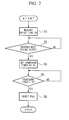
- FIG. 2 is a flow chart showing the operation of the start control device.
- FIG. 3 is a timing chart showing crank pulse signals, generated voltage, and injection timing of an injector.
- Hereunder is a description of an embodiment of an engine start control device and a start control method of the present invention, with reference to the figures.
- FIG. 1 is a system configuration diagram for an outboard motor according to the present embodiment. An engine (not shown in the figure) of an
outboard motor 1, has a fuel pump (P) 3 which is driven via anECU 2. Fuel supplied by thefuel pump 3 is injected by injectors (INJ #1 to 4) 4, ignited by an igniter by energizing an ignition (IG)coil 5, and burned in the cylinders. - The igniter ignites at an optimum crank angle for each cylinder, based on a crank pulse signal. Power is supplied from the
battery 8 to theinjector 4 in conformance with the ignition timing, to give fuel injection by theinjector 4. - The
ECU 2, as well as performing control of, the amount of fuel supplied to theinjectors 4, the injection timing, and the ignition timing by theignition coil 5, performs control of aPTC heater 18 for idle control, and open and close control of a relay 7 provided in anaccessory circuit 6 for an accessory (ACC) 19 such as a lamp or the like. TheECU 2 includes: a CPU, being a central processing unit for performing a range of calculation processing; a RAM (Random Access Memory) used for storing data partway through the calculations by the CPU; a ROM (Read Only Memory) for storing programs that the CPU executes, tables, maps and the like; and an EEP-ROM (Electronically Erasable and Programmable Read Only Memory) for storing backup data and the like. On receiving power supplied from apower circuit 9 connected to abattery 8, theECU 2 starts operating. - To the ECU 2A is input signals from; a crank angle (CRK) sensor, a throttle opening (TH) sensor, a MAP sensor for detecting the inlet negative pressure of the engine, a water temperature sensor for detecting the temperature of engine cooling water, an inlet temperature sensor, an overheat sensor, an engine cooling oil pressure switch, a stop switch for emergency stop, and an engine speed (NE) sensor. Moreover, information related to the output voltage of the generator is input from a later mentioned regulator 15. Furthermore, as required, warnings are given by a
warning buzzer 10 and awarning lamp 11, and reception and transmission of data to and from afault diagnosis device 12 is performed. -
Reference symbol 13 denotes an electrical generator (ACG). Theelectrical generator 13 generates electricity at the time of engine drive, and charges the battery (BAT) 8 of thepower circuit 9 via a rectifier (REC) 14, and a regulator (REG) 15 for regulating the voltage. Theelectrical generator 13 also generates electricity in the case of a starting operation by amanual recoil starter 16, and generates starting power for theECU 2 when the battery capacity is low, which is described later, driving power to the fuel pump (P) 3, and the like. Therecoil starter 16 is a starter which starts the engine by a starter rope being pulled.Reference symbol 17 denotes a main switch of thepower circuit 9. - Next is a description of engine start control based on the flow chart of FIG. 2.
- This flow chart shows the processing of the
ECU 2 for in the case where starting is performed using therecoil starter 16, in a situation where the battery residual capacity has dropped, or it is cold, so that the necessary voltage cannot be obtained from the battery 8 (when the battery capacity is low). - In FIG. 2, when a starting operation is performed by pulling on a starter rope of the
recoil starter 16, in step S1 (offset time measuring device), using the crank pulse signal as a reference, a time difference between the crank pulse signal and the peak of the voltage generated by the generator is measured as an offset time To. - To be specific, for a charging current armature of the
generator 13, a three-phase, 18 electrode type is used, and detecting sections are provided in the flywheel every 20 degrees corresponding to this. That is, when thegenerator 13 is driven by a starting operation of therecoil starter 16 in a situation in which power cannot be obtained from thebattery 8, the generated output voltage from thegenerator 13 fluctuates widely as shown in FIG. 3. At this time, by matching the cycle of the crank pulse signal with the cycle (power generation wave form) of the voltage generated by thegenerator 13, it is possible to understand the cycle of the voltage generated by thegenerator 13, more specifically, the timing at which the generated voltage reaches a peak, with reference to the cycle of the crank pulse signal. - In the case of FIG. 3, the time from a rising point CPn (to be specific, the fourth rising point CP4 (located at 60 degrees)) to the next peak VPm (to be specific, VP5, being the fifth peak) of the generated voltage is measured as an offset time To. For this measurement, the
ECU 2 makes a computation immediately after the engine starts, based on an input signal from the crank angle sensor and an input signal from the regulator. Here, n and m = 1, 2, 3, 4 (positive integers). - Next, in step S2, it is determined whether or not the rising point CP5 (located at 80 degrees) of the next crank pulse signal is reached. In the case where the determination result is "NO", the flow proceeds again to step S2, while in the case where the determination result is "YES", the flow proceeds to step S3.
- In step S3 (fuel injection timing setting device), a countdown timer is set to T0, and the flow proceeds to step S4.
- In step S4 (fuel injection timing setting device), it is determined whether the countdown timer = 0 or not. In the case where the determination result is "NO", the flow proceeds again to step S4, while in the case where the determination result is "YES", the flow proceeds to step S5. Then in step S5, fuel is injected from the
injector 4. - At this time, since the voltage generated by the
generator 13 reaches a peak in conformance with the timing for injecting fuel from theinjector 4, it is possible to inject fuel in a state where a sufficient fuel injection amount is assured. Therefore, there is no possibility of flameout due to insufficient fuel. - As a result, according to the present embodiment, it is possible to measure the time difference between a crank pulse signal and a peak of the generated voltage, and inject fuel from the
injector 4 when the voltage generated by thegenerator 13 reaches a peak, after the crank pulse signal has been output. Therefore, it is possible to start the engine in a short time after the starting operation, and at the time that the supply voltage to theinjector 4 reaches a sufficient level. - Furthermore, since a sufficient amount of fuel can be injected from the
injector 4 at a timing in conformance with a peak of the voltage generated by thegenerator 13, it is possible to start the engine reliably. - The present invention is not limited in the above-described embodiment. For example, in the present embodiment, an
outboard motor 1 incorporating arecoil starter 16 is described as an example. However, the invention can also be used for a start control device of a three-wheel, or four-wheel, dune buggy incorporating a kick starter. Furthermore, in the above-described embodiment, the example is given of a case in which abattery 8 and arecoil starter 16 are used together. However, the invention can also be applied to a battery-less situation. - Furthermore, in the present embodiment, an engine start control device of the present invention is realized in which the procedures that are executed in the engine start control device are stored in a computer readable recording medium, and a program stored in this recording medium is read by a computer system for execution. The computer system mentioned here includes an OS (Operating System), and hardware such as peripheral equipment and the like.
- Moreover, in the case where a WWW (World Wide Web) system is used, "computer system" also includes a website provider environment (or display environment).
- Furthermore, "computer readable recording medium" means a portable medium such as a flexible disc, optical magnetic disc, ROM, CD-ROM, or the like, and memory storage such as a hard disc or the like, built into a computer system. Moreover, "computer readable recording medium" also includes a system where the program is transmitted via a network such as the Internet or the like, or a communication circuit such as a telephone line, or the like, and in which a program is stored temporarily in a volatile memory (RAM) in a computer system, being a client.
- Furthermore, the above-described program may be transmitted from a computer system in which the program is stored in memory storage or the like to another computer system via a transmission medium, or by transmitted waves in the transmission medium. Here, "transmission medium" means a medium having a function of transmitting information, such as a network (communication network) such as the Internet, or a communication circuit (communication line) such as a telephone line.
- Moreover, the program may realize part of the aforementioned function. Furthermore, it may be a type that can be realized by a combination of the aforementioned function and a program already stored in a computer system, that is, a so-called differential file (differential program).
- According to the present invention, it is possible to inject fuel to an injector at the time of a peak of the voltage generated by the generator, which changes cyclically corresponding to a crank pulse signal. Therefore, it is possible to start an engine in a short time after the starting operation, and at a timing where the supply voltage to the injector reaches a sufficient level.
Claims (3)
- An engine start control device capable of starting upon receiving generated power from a generator which is driven by a starter, comprising
a fuel injection timing setting device which makes a power generation waveform of said generator correspond to a crank pulse signal, and outputs a fuel injection signal to an injector for injecting fuel to said engine in conformance with a crank pulse signal for when a voltage of said generated power reaches a peak value after a starting operation of said starter. - An engine start control device capable of starting upon receiving power generated from a generator which is driven by a starter, comprising:an offset time measuring device which measures an offset time of a peak timing of a voltage generated by a generator with respect to a crank pulse signal, immediately after a starting operation of said starter; and a fuel injection timing setting device which outputs a fuel injection signal to an injector for injecting fuel to said engine, after said offset time has elapsed after the crank pulse signal has been output.
- A start control method for an engine capable of starting upon receiving generated power from a generator which is driven by a starter, comprising injecting fuel from an injector for injecting fuel to said engine, in conformance with a peak timing of a voltage generated by said generator.
Applications Claiming Priority (2)
| Application Number | Priority Date | Filing Date | Title |
|---|---|---|---|
| JP2003107795A JP2004316451A (en) | 2003-04-11 | 2003-04-11 | Engine start control device and start control method |
| PCT/JP2004/004924 WO2004092563A1 (en) | 2003-04-11 | 2004-04-05 | Start controller and start control method of engine |
Publications (1)
| Publication Number | Publication Date |
|---|---|
| EP1614883A1 true EP1614883A1 (en) | 2006-01-11 |
Family
ID=33295868
Family Applications (1)
| Application Number | Title | Priority Date | Filing Date |
|---|---|---|---|
| EP04725835A Withdrawn EP1614883A1 (en) | 2003-04-11 | 2004-04-05 | Start controller and start control method of engine |
Country Status (4)
| Country | Link |
|---|---|
| US (1) | US7231908B2 (en) |
| EP (1) | EP1614883A1 (en) |
| JP (1) | JP2004316451A (en) |
| WO (1) | WO2004092563A1 (en) |
Families Citing this family (5)
| Publication number | Priority date | Publication date | Assignee | Title |
|---|---|---|---|---|
| JP4173502B2 (en) * | 2005-08-05 | 2008-10-29 | 株式会社ケーヒン | Electronic fuel injection control device |
| JP4925976B2 (en) * | 2007-08-29 | 2012-05-09 | 株式会社ケーヒン | Internal combustion engine control device |
| JP2009185717A (en) * | 2008-02-06 | 2009-08-20 | Yamaha Motor Co Ltd | Fuel injection control device and vehicle |
| US8347862B2 (en) * | 2009-12-23 | 2013-01-08 | Ford Global Technologies, Llc | System and method for injecting fuel to a gaseous fueled engine |
| JP2015081540A (en) | 2013-10-22 | 2015-04-27 | 富士重工業株式会社 | engine |
Family Cites Families (9)
| Publication number | Priority date | Publication date | Assignee | Title |
|---|---|---|---|---|
| DE3310920A1 (en) * | 1983-03-25 | 1984-09-27 | Robert Bosch Gmbh, 7000 Stuttgart | METHOD AND DEVICE FOR DETERMINING THE INJECTION TIME OF INTERNAL COMBUSTION ENGINES DURING THE STARTING PROCESS |
| DE3539732C2 (en) * | 1984-11-09 | 1994-11-17 | Nippon Denso Co | Electronically controlled fuel injection system for an internal combustion engine |
| JP2524168B2 (en) * | 1987-08-20 | 1996-08-14 | ヤンマーディーゼル株式会社 | Engine starter |
| JPS6453058U (en) | 1987-09-25 | 1989-03-31 | ||
| SE459822B (en) * | 1987-11-24 | 1989-08-07 | Saab Scania Ab | PROCEDURES TO RECOVER CAREFULLY CHARGING A IGNITION CAPACITOR IN A CAPACITIVE IGNITION SYSTEM FOR STARTING COMBUSTION ENGINES |
| JP3014835B2 (en) | 1991-11-05 | 2000-02-28 | 本田技研工業株式会社 | Engine battery-less electronic fuel injection control device |
| JP3858582B2 (en) | 2000-09-29 | 2006-12-13 | 国産電機株式会社 | Batteryless fuel injection device for multi-cylinder internal combustion engine |
| JP3974332B2 (en) * | 2001-01-10 | 2007-09-12 | 本田技研工業株式会社 | Control method of electromagnetic fuel pump |
| JP2004162691A (en) * | 2002-09-17 | 2004-06-10 | Kokusan Denki Co Ltd | Electronic engine control device |
-
2003
- 2003-04-11 JP JP2003107795A patent/JP2004316451A/en active Pending
-
2004
- 2004-04-05 WO PCT/JP2004/004924 patent/WO2004092563A1/en not_active Ceased
- 2004-04-05 EP EP04725835A patent/EP1614883A1/en not_active Withdrawn
- 2004-04-05 US US10/552,614 patent/US7231908B2/en not_active Expired - Fee Related
Non-Patent Citations (1)
| Title |
|---|
| See references of WO2004092563A1 * |
Also Published As
| Publication number | Publication date |
|---|---|
| JP2004316451A (en) | 2004-11-11 |
| US7231908B2 (en) | 2007-06-19 |
| WO2004092563A1 (en) | 2004-10-28 |
| US20060278200A1 (en) | 2006-12-14 |
Similar Documents
| Publication | Publication Date | Title |
|---|---|---|
| RU2670581C2 (en) | Device and method for starting engine of mild hybrid vehicle | |
| KR100871308B1 (en) | Control apparatus of internal combustion engine | |
| JP4925976B2 (en) | Internal combustion engine control device | |
| CN1330871C (en) | Electronic controlled fuel injection apparatus of internal combustion engine | |
| KR20120041330A (en) | Educational simulation of electronic control system of automobile engine | |
| US7228222B2 (en) | Engine start control device and start control method | |
| US7481200B2 (en) | Start-up control of internal combustion engines | |
| US7231908B2 (en) | Engine start control device and start control method | |
| CN104204480B (en) | The starting device of Diesel engine and starting method | |
| JP2004162691A (en) | Electronic engine control device | |
| CN100497934C (en) | Controller controlling electric machine operated to start internal combustion engine | |
| JPH11173188A (en) | Fuel injection control device for internal combustion engine | |
| JP5910176B2 (en) | Start control device for compression self-ignition engine | |
| JP5842678B2 (en) | Start control method and apparatus for compression self-ignition engine | |
| RU2706330C2 (en) | Method for adjustment of ignition coil | |
| JP2013194637A (en) | Engine control unit | |
| RU2387869C1 (en) | Device to reveal ignition plug fault | |
| US20180142659A1 (en) | Control device for vehicle | |
| JP2002242739A (en) | Control unit for diesel engine | |
| CN110344958B (en) | Control devices for hybrid vehicles | |
| KR102895429B1 (en) | Engine cranking system and method for hybrid vehicle | |
| JP2019203456A (en) | Engine stop controller | |
| CN111219280A (en) | Engine starting system and control method thereof | |
| JP2008215226A (en) | Fuel injection control device of diesel engine | |
| JP2025183031A (en) | Start control device for internal combustion engine |
Legal Events
| Date | Code | Title | Description |
|---|---|---|---|
| PUAI | Public reference made under article 153(3) epc to a published international application that has entered the european phase |
Free format text: ORIGINAL CODE: 0009012 |
|
| 17P | Request for examination filed |
Effective date: 20051011 |
|
| AK | Designated contracting states |
Kind code of ref document: A1 Designated state(s): AT BE BG CH CY CZ DE DK EE ES FI FR GB GR HU IE IT LI LU MC NL PL PT RO SE SI SK TR |
|
| AX | Request for extension of the european patent |
Extension state: AL HR LT LV MK |
|
| DAX | Request for extension of the european patent (deleted) | ||
| RBV | Designated contracting states (corrected) |
Designated state(s): IT |
|
| REG | Reference to a national code |
Ref country code: DE Ref legal event code: 8566 |
|
| STAA | Information on the status of an ep patent application or granted ep patent |
Free format text: STATUS: THE APPLICATION IS DEEMED TO BE WITHDRAWN |
|
| 18D | Application deemed to be withdrawn |
Effective date: 20091031 |