EP1614836A2 - Plastic lock for refrigeration or freezer appliances - Google Patents
Plastic lock for refrigeration or freezer appliances Download PDFInfo
- Publication number
- EP1614836A2 EP1614836A2 EP05104402A EP05104402A EP1614836A2 EP 1614836 A2 EP1614836 A2 EP 1614836A2 EP 05104402 A EP05104402 A EP 05104402A EP 05104402 A EP05104402 A EP 05104402A EP 1614836 A2 EP1614836 A2 EP 1614836A2
- Authority
- EP
- European Patent Office
- Prior art keywords
- cylinder
- lock
- key
- rocker element
- hole
- Prior art date
- Legal status (The legal status is an assumption and is not a legal conclusion. Google has not performed a legal analysis and makes no representation as to the accuracy of the status listed.)
- Withdrawn
Links
Images
Classifications
-
- F—MECHANICAL ENGINEERING; LIGHTING; HEATING; WEAPONS; BLASTING
- F25—REFRIGERATION OR COOLING; COMBINED HEATING AND REFRIGERATION SYSTEMS; HEAT PUMP SYSTEMS; MANUFACTURE OR STORAGE OF ICE; LIQUEFACTION SOLIDIFICATION OF GASES
- F25D—REFRIGERATORS; COLD ROOMS; ICE-BOXES; COOLING OR FREEZING APPARATUS NOT OTHERWISE PROVIDED FOR
- F25D29/00—Arrangement or mounting of control or safety devices
- F25D29/006—Safety devices
-
- E—FIXED CONSTRUCTIONS
- E05—LOCKS; KEYS; WINDOW OR DOOR FITTINGS; SAFES
- E05B—LOCKS; ACCESSORIES THEREFOR; HANDCUFFS
- E05B15/00—Other details of locks; Parts for engagement by bolts of fastening devices
- E05B15/16—Use of special materials for parts of locks
- E05B15/1635—Use of special materials for parts of locks of plastics materials
-
- F—MECHANICAL ENGINEERING; LIGHTING; HEATING; WEAPONS; BLASTING
- F25—REFRIGERATION OR COOLING; COMBINED HEATING AND REFRIGERATION SYSTEMS; HEAT PUMP SYSTEMS; MANUFACTURE OR STORAGE OF ICE; LIQUEFACTION SOLIDIFICATION OF GASES
- F25D—REFRIGERATORS; COLD ROOMS; ICE-BOXES; COOLING OR FREEZING APPARATUS NOT OTHERWISE PROVIDED FOR
- F25D23/00—General constructional features
- F25D23/02—Doors; Covers
- F25D23/028—Details
-
- E—FIXED CONSTRUCTIONS
- E05—LOCKS; KEYS; WINDOW OR DOOR FITTINGS; SAFES
- E05B—LOCKS; ACCESSORIES THEREFOR; HANDCUFFS
- E05B19/00—Keys; Accessories therefor
- E05B19/26—Use of special materials for keys
-
- E—FIXED CONSTRUCTIONS
- E05—LOCKS; KEYS; WINDOW OR DOOR FITTINGS; SAFES
- E05B—LOCKS; ACCESSORIES THEREFOR; HANDCUFFS
- E05B15/00—Other details of locks; Parts for engagement by bolts of fastening devices
- E05B15/16—Use of special materials for parts of locks
- E05B15/1635—Use of special materials for parts of locks of plastics materials
- E05B2015/1642—Use of special materials for parts of locks of plastics materials for the whole lock
-
- E—FIXED CONSTRUCTIONS
- E05—LOCKS; KEYS; WINDOW OR DOOR FITTINGS; SAFES
- E05B—LOCKS; ACCESSORIES THEREFOR; HANDCUFFS
- E05B65/00—Locks or fastenings for special use
- E05B65/0042—For refrigerators or cold rooms
-
- E—FIXED CONSTRUCTIONS
- E05—LOCKS; KEYS; WINDOW OR DOOR FITTINGS; SAFES
- E05C—BOLTS OR FASTENING DEVICES FOR WINGS, SPECIALLY FOR DOORS OR WINDOWS
- E05C3/00—Fastening devices with bolts moving pivotally or rotatively
- E05C3/02—Fastening devices with bolts moving pivotally or rotatively without latching action
- E05C3/04—Fastening devices with bolts moving pivotally or rotatively without latching action with operating handle or equivalent member rigid with the bolt
- E05C3/041—Fastening devices with bolts moving pivotally or rotatively without latching action with operating handle or equivalent member rigid with the bolt rotating about an axis perpendicular to the surface on which the fastener is mounted
- E05C3/042—Fastening devices with bolts moving pivotally or rotatively without latching action with operating handle or equivalent member rigid with the bolt rotating about an axis perpendicular to the surface on which the fastener is mounted the handle being at one side, the bolt at the other side or inside the wing
-
- F—MECHANICAL ENGINEERING; LIGHTING; HEATING; WEAPONS; BLASTING
- F25—REFRIGERATION OR COOLING; COMBINED HEATING AND REFRIGERATION SYSTEMS; HEAT PUMP SYSTEMS; MANUFACTURE OR STORAGE OF ICE; LIQUEFACTION SOLIDIFICATION OF GASES
- F25D—REFRIGERATORS; COLD ROOMS; ICE-BOXES; COOLING OR FREEZING APPARATUS NOT OTHERWISE PROVIDED FOR
- F25D2400/00—General features of, or devices for refrigerators, cold rooms, ice-boxes, or for cooling or freezing apparatus not covered by any other subclass
- F25D2400/10—Refrigerator top-coolers
Definitions
- the present invention relates to a mainly plastic lock for refrigeration appliances in accordance with the introduction to the main claim. It relates in particular to a lock for horizontal freezers.
- Conventional vertical freezers present locks enabling the lid to be opened by a person possessing the relative key.
- the locks currently installed on such freezers are of the cylinder type and substantially of metal construction.
- plastic locks have been used in certain applications, such as computer disk containers, compact disk containers or liquid soap containers.
- An object of the present invention is to provide a lock mainly of plastic construction for use with horizontal freezers, as an alternative to those of the known art.
- a further object of the present invention is to provide a lock for horizontal freezers which is able to withstand at least a "banal" break-in attempt.
- It comprises a support 2 which can be fixed to the lid of a conventional horizontal freezer by holes 3.
- a projection 4 provided with a cylindrical through hole 5.
- the hole 5 presents a first groove 6 and a second groove 7 which are disposed axially along the inner surface 5a of the hole 5 and extend radially from the hole 5. Said grooves 6, 7 are spaced apart by 90° on a circumferential arc having the hole 5 as centre.
- Housed in the hole 5 there is a cylinder 8, well visible in Figure 5. It presents a surface in the form of a cylindrical sector 8a, which when the cylinder 8 is rotating slides along an inner surface 5a of the hole 5.
- a portion 10 of square cross-section from which a U-shaped portion 11 extends.
- the portion 10 of square cross-section is intended to receive an aperture 12a of similar shape, provided in a hook-shaped element or hook 12.
- the aperture 12a and portion 10 of square cross-section render the cylinder 8 and hook 12 torsionally rigid.
- the cylinder 8 is inserted into the hole 5, its collar or flange 8c abutting against the projection 4.
- the cylinder 8 is axially secured to the hook element 12 by a fixing washer 13. This fixing method axially blocks the cylinder 8 within the hole 5.
- the hook 12 cooperates conventionally with a pin (not shown) to lock the freezer lid.
- the interior of the cylinder 8 presents a passageway 19 which opens in a side thereof of substantially square cross-section (see Figure 3), through which the key 9 is inserted, the use of which is clarified hereinafter.
- the rocker element 15 presents a shaped profile 20 which by cooperating with a corresponding shaped profile 21 of the key 9 (comprising shoulders 21A defining a recess 21 B into which the profile 20 penetrates), centres the rocker element relative to the key 9 when this latter is inserted into the passageway 19.
- the key 9 presents, in addition to the profile 21 corresponding to the profile 20 of the rocker element, a seat 23 enabling the rocker element 15 to move towards the key and substantially to receive it with the tooth 18 disengaged from the groove 6, 7.
- the key 9, cylinder 8, support 2, fixing washer 13 and hook 12 are made of ABS.
- the tooth 18 can be provide integral with the hole 5, while the groove 6, 7 can be provided in the rocker element 15.
Landscapes
- Engineering & Computer Science (AREA)
- Chemical & Material Sciences (AREA)
- Combustion & Propulsion (AREA)
- Physics & Mathematics (AREA)
- Mechanical Engineering (AREA)
- Thermal Sciences (AREA)
- General Engineering & Computer Science (AREA)
- Lock And Its Accessories (AREA)
- Compositions Of Macromolecular Compounds (AREA)
Abstract
Description
- The present invention relates to a mainly plastic lock for refrigeration appliances in accordance with the introduction to the main claim. It relates in particular to a lock for horizontal freezers.
- Conventional vertical freezers present locks enabling the lid to be opened by a person possessing the relative key.
- The locks currently installed on such freezers are of the cylinder type and substantially of metal construction.
- These locks have the drawback of being fairly costly, they present oxidation problems which can result in malfunction, and are also bulky and heavy.
- To overcome these technical problems, plastic locks have been used in certain applications, such as computer disk containers, compact disk containers or liquid soap containers.
- However these locks present safety problems, given that they can be easily tampered with and are generally operable by any object having a profile similar to the lock recess.
- An object of the present invention is to provide a lock mainly of plastic construction for use with horizontal freezers, as an alternative to those of the known art.
- A further object of the present invention is to provide a lock for horizontal freezers which is able to withstand at least a "banal" break-in attempt. These and further objects which will be apparent to the expert of the art are attained by a lock in accordance with the technical teachings of the accompanying claims.
- Further characteristics and advantages of the invention will be apparent from the description of one embodiment of the invention, illustrated by way of non-limiting example in the accompanying drawings, in which:
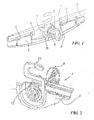
- Figure 1 is a perspective view of a lock for horizontal freezers;
- Figure 2 is a perspective view of the lock taken from a different angle;
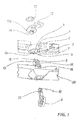
- Figure 3 is an exploded perspective view of the lock seen from above;
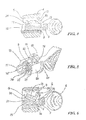
- Figure 4 is a section through the lock, showing its operation, with the key partly inserted into the lock;
- Figure 5 is a perspective view of the key and of the lock on which it acts;
- Figure 6 is a section through the lock, with the key totally inserted therein; and
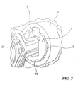
- Figure 7 is an enlarged front perspective view of part of the lock of Figure 1 during use.
- Said figures show a horizontal freezer lock indicated overall by 1.
- It comprises a
support 2 which can be fixed to the lid of a conventional horizontal freezer byholes 3. - Integral with the
support 2 there is a projection 4 provided with a cylindrical throughhole 5. Thehole 5 presents a first groove 6 and asecond groove 7 which are disposed axially along theinner surface 5a of thehole 5 and extend radially from thehole 5. Saidgrooves 6, 7 are spaced apart by 90° on a circumferential arc having thehole 5 as centre. Housed in thehole 5 there is acylinder 8, well visible in Figure 5. It presents a surface in the form of acylindrical sector 8a, which when thecylinder 8 is rotating slides along aninner surface 5a of thehole 5. Centrally, from a closedend 8b of the cylinder there extends aportion 10 of square cross-section, from which aU-shaped portion 11 extends. Theportion 10 of square cross-section is intended to receive anaperture 12a of similar shape, provided in a hook-shaped element orhook 12. Theaperture 12a andportion 10 of square cross-section render thecylinder 8 and hook 12 torsionally rigid. - As can be seen in the figures, the
cylinder 8 is inserted into thehole 5, its collar orflange 8c abutting against the projection 4. Thecylinder 8 is axially secured to thehook element 12 by afixing washer 13. This fixing method axially blocks thecylinder 8 within thehole 5. - In use, the
hook 12 cooperates conventionally with a pin (not shown) to lock the freezer lid. - The interior of the
cylinder 8 presents apassageway 19 which opens in a side thereof of substantially square cross-section (see Figure 3), through which the key 9 is inserted, the use of which is clarified hereinafter. - From the
cylindrical sector surface 8a of thecylinder 8 there branch twoelastic appendices 16 supporting arocker element 15. The torsionallyelastic appendices 16 maintain therocker element 15 in a rest position visible in Figure 4, i.e. with atooth 18 projecting therefrom engaged in the groove 6. With therocker element 15 in its rest position, thecylinder 8 is therefore unable to rotate within thehole 5, as it is torsionally engaged with thehole 5 by the form constraint provided by thetooth 18 and thegrooves 6, 7. - Facing the
passageway 19, therocker element 15 presents ashaped profile 20 which by cooperating with a correspondingshaped profile 21 of the key 9 (comprising shoulders 21A defining a recess 21 B into which theprofile 20 penetrates), centres the rocker element relative to the key 9 when this latter is inserted into thepassageway 19. - The insertion of the key 9 into the
passageway 19 does not change the position of therocker element 15 until the key 9 is inserted completely into thepassageway 19, i.e. substantially until the position of the key 9 is that shown in Figure 4 and in Figure 5. - As can be seen, the key 9 presents, in addition to the
profile 21 corresponding to theprofile 20 of the rocker element, aseat 23 enabling therocker element 15 to move towards the key and substantially to receive it with thetooth 18 disengaged from thegroove 6, 7. - In this respect, when the key 9 has been completely inserted into the
passageway 19, aprotuberance 24 of therocker element 15 contacts itsprofile 21, movement of the key 9 in the direction of the arrow F of Figure 6 causing therocker element 15 to rotate in the direction of the arrows G about theelastic appendices 16. - Hence with the key 9 abutting against a
stop 25, thetooth 18 of therocker element 15 is disengaged and free from the groove 6, and the key 9 (and consequently the cylinder 8) can be rotated to enable thehook 12 to be freed from the pin (not shown) and the lid to be opened. - With the
tooth 15 disengaged from thesecond groove 7, and hence with the key 9 extracted from thepassageway 19, thehook 12 is horizontal and the lid hence unlocked. - To complete the description it should be noted that the
cylinder 8, the hole and all illustrated devices are covered by a plastic masking element 50 (Figure 3). - Advantageously the key 9,
cylinder 8, support 2,fixing washer 13 andhook 12 are made of ABS. - A preferred embodiment has been illustrated, however others can be conceived using the same inventive concept.
- For example, the
tooth 18 can be provide integral with thehole 5, while thegroove 6, 7 can be provided in therocker element 15.
Claims (12)
- A lock (1) for refrigeration or freezer appliances, in particular horizontal freezers, comprising a cylinder (8) rotating within a corresponding seat or hole (5), said cylinder (8) being rotated by a key (9) engaged in a passageway (19) formed in the cylinder (8), said rotation operating a locking device (12), characterised in that said cylinder (8) presents, elastically constrained thereto, a rocker element (15) which can assume two positions, namely a first rest position, in which the element (15) is torsionally engaged with said hole (5) by a form constraint and in which rotation of the cylinder (8) is prevented, and a second position, with the key (9) completely inserted into said passageway (10), in which said element is torsionally disengaged from said hole (5), so that rotating the cylinder (8) releases or locks the locking device (12).
- A lock as claimed in claim 1, wherein said form constraint is provided by a tooth (18) engaging in a groove (6, 7).
- A lock as claimed in claim 2, characterised in that said tooth (18) is provided on said rocker element (16), said groove (6, 7) being provided in the inner surface (5a) of said hole (5).
- A lock as claimed in claim 1, characterised in that said locking device is a hook (12) torsionally rigid with said cylinder (8), said hook (12) cooperating with a pin to lock said appliance.
- A lock as claimed in claim 4, characterised in that said hook (12) presents an aperture (12a), said aperture being torsionally engaged on a portion (8b) of the cylinder (8).
- A lock as claimed in claim 1, characterised in that said cylinder (8) is axially fixed into said hole (5) by a washer (13) and a collar (8c) of the cylinder (8), said washer (13) simultaneously blocking said hook (12).
- A lock as claimed in claim 1, characterised in that said rocker element (15) is suspended from and secured to a pair of torsionally elastic appendices (16) projecting from said cylinder (8).
- A lock as claimed in claim 1, characterised in that said rocker element (15) presents a profile (20) of shape corresponding to that (21) of said key (9), said profiles (20, 21) mutually centering the key (9) and rocker element (15) when the key (9) is inserted into the passageway (19).
- A lock as claimed in claim 1, characterised in that said key (9) presents a seat (23) to receive the rocker element (15) when said rocker element (15) is in its second working position, disengaged from said groove (6, 7).
- A lock as claimed in claim 1, characterised in that said rocker element (15) presents at least one protuberance (24) able to slide relatively on the profile (21) of said key (9), with the key totally inserted into the passageway (19) said protuberance (24) raising the rocker element (15) and moving it into said second position, in which said form constraint is inoperative.
- A lock as claimed in claim 1, characterised in that said passageway (19) presents a travel stop (25) for said key (9).
- A lock as claimed in claim 1, characterised in that said cylinder (8) and said key (9) are of plastic construction.
Applications Claiming Priority (1)
| Application Number | Priority Date | Filing Date | Title |
|---|---|---|---|
| ITMI20040288 ITMI20040288U1 (en) | 2004-06-15 | 2004-06-15 | PLASTIC LOCK FOR REFRIGERATOR OR FREEZER APPLIANCES |
Publications (2)
| Publication Number | Publication Date |
|---|---|
| EP1614836A2 true EP1614836A2 (en) | 2006-01-11 |
| EP1614836A3 EP1614836A3 (en) | 2009-11-18 |
Family
ID=35198092
Family Applications (1)
| Application Number | Title | Priority Date | Filing Date |
|---|---|---|---|
| EP05104402A Withdrawn EP1614836A3 (en) | 2004-06-15 | 2005-05-24 | Plastic lock for refrigeration or freezer appliances |
Country Status (2)
| Country | Link |
|---|---|
| EP (1) | EP1614836A3 (en) |
| IT (1) | ITMI20040288U1 (en) |
Cited By (1)
| Publication number | Priority date | Publication date | Assignee | Title |
|---|---|---|---|---|
| WO2007139904A3 (en) * | 2006-05-24 | 2008-02-07 | David Joseph Bolles | Locking mechanism for a theft-resistant mailbox |
Family Cites Families (5)
| Publication number | Priority date | Publication date | Assignee | Title |
|---|---|---|---|---|
| US3626712A (en) * | 1970-09-21 | 1971-12-14 | Gen Motors Corp | Safety lock for food freezers or refrigerators |
| FR2231240A6 (en) * | 1973-05-22 | 1974-12-20 | Neiman Exploitation Brevets | |
| DE3503660A1 (en) * | 1985-02-04 | 1986-08-07 | Fa. Wilhelm Karrenberg, 5620 Velbert | Locking device with locking cylinder and flat key |
| US4910982A (en) * | 1988-10-14 | 1990-03-27 | Engineered Security Products Corporation | Self-assembling locking device |
| US5479800A (en) * | 1992-10-19 | 1996-01-02 | Fort Lock Corporation | Plastic lock |
-
2004
- 2004-06-15 IT ITMI20040288 patent/ITMI20040288U1/en unknown
-
2005
- 2005-05-24 EP EP05104402A patent/EP1614836A3/en not_active Withdrawn
Cited By (1)
| Publication number | Priority date | Publication date | Assignee | Title |
|---|---|---|---|---|
| WO2007139904A3 (en) * | 2006-05-24 | 2008-02-07 | David Joseph Bolles | Locking mechanism for a theft-resistant mailbox |
Also Published As
| Publication number | Publication date |
|---|---|
| ITMI20040288U1 (en) | 2004-09-15 |
| EP1614836A3 (en) | 2009-11-18 |
Similar Documents
| Publication | Publication Date | Title |
|---|---|---|
| EP0675248B2 (en) | Cylinder lock device resistible against unauthorized unlocking | |
| US5931035A (en) | Cylinder type lock arrangement | |
| US20010005995A1 (en) | Lockable sash assembly | |
| US6604393B2 (en) | Lock system operable with multiple keys | |
| CA2054078C (en) | Lock accessory | |
| CA1121610A (en) | Permutation controlled padlock | |
| US20110167883A1 (en) | Side hung type door or window handle lock | |
| US4646547A (en) | Dead bolt combination lock | |
| JP2003206665A (en) | Latching structure | |
| US20050160775A1 (en) | Deadbolt | |
| EP3276111B1 (en) | Lock with a slide for covering lock core | |
| AU2016222285B2 (en) | A latch assembly for a sliding door | |
| KR101491072B1 (en) | Digital door lock installation structure for tempered glass door | |
| EP2889443B1 (en) | Lock for in-wall frames of retractable sliding doors | |
| KR20040075674A (en) | Door locking handle device for drawing rotating operating type door | |
| AU2008265749B2 (en) | Combination lock | |
| JPH0252752B2 (en) | ||
| JP7199983B2 (en) | One-touch mounting handle | |
| US8196973B2 (en) | Device for childproofing a door lock | |
| JP4987160B2 (en) | Game machine locking device | |
| CN209908142U (en) | Lock set | |
| JP2591033Y2 (en) | Cylinder lock | |
| JP2023045032A (en) | Latch lock | |
| US2169895A (en) | Padlock | |
| US3246495A (en) | Shutter assembly |
Legal Events
| Date | Code | Title | Description |
|---|---|---|---|
| PUAI | Public reference made under article 153(3) epc to a published international application that has entered the european phase |
Free format text: ORIGINAL CODE: 0009012 |
|
| AK | Designated contracting states |
Kind code of ref document: A2 Designated state(s): AT BE BG CH CY CZ DE DK EE ES FI FR GB GR HU IE IS IT LI LT LU MC NL PL PT RO SE SI SK TR |
|
| AX | Request for extension of the european patent |
Extension state: AL BA HR LV MK YU |
|
| PUAL | Search report despatched |
Free format text: ORIGINAL CODE: 0009013 |
|
| AK | Designated contracting states |
Kind code of ref document: A3 Designated state(s): AT BE BG CH CY CZ DE DK EE ES FI FR GB GR HU IE IS IT LI LT LU MC NL PL PT RO SE SI SK TR |
|
| AX | Request for extension of the european patent |
Extension state: AL BA HR LV MK YU |
|
| AKX | Designation fees paid | ||
| REG | Reference to a national code |
Ref country code: DE Ref legal event code: 8566 |
|
| STAA | Information on the status of an ep patent application or granted ep patent |
Free format text: STATUS: THE APPLICATION IS DEEMED TO BE WITHDRAWN |
|
| 18D | Application deemed to be withdrawn |
Effective date: 20100519 |