EP1614791A2 - Wiper device for sewing machine - Google Patents
Wiper device for sewing machine Download PDFInfo
- Publication number
- EP1614791A2 EP1614791A2 EP05014675A EP05014675A EP1614791A2 EP 1614791 A2 EP1614791 A2 EP 1614791A2 EP 05014675 A EP05014675 A EP 05014675A EP 05014675 A EP05014675 A EP 05014675A EP 1614791 A2 EP1614791 A2 EP 1614791A2
- Authority
- EP
- European Patent Office
- Prior art keywords
- needle
- wiper
- thread
- needle bar
- bar
- Prior art date
- Legal status (The legal status is an assumption and is not a legal conclusion. Google has not performed a legal analysis and makes no representation as to the accuracy of the status listed.)
- Granted
Links
Images







Classifications
-
- D—TEXTILES; PAPER
- D05—SEWING; EMBROIDERING; TUFTING
- D05B—SEWING
- D05B65/00—Devices for severing the needle or lower thread
- D05B65/06—Devices for severing the needle or lower thread and for disposing of the severed thread end ; Catching or wiping devices for the severed thread
-
- D—TEXTILES; PAPER
- D05—SEWING; EMBROIDERING; TUFTING
- D05B—SEWING
- D05B65/00—Devices for severing the needle or lower thread
- D05B65/02—Devices for severing the needle or lower thread controlled by the sewing mechanisms
-
- D—TEXTILES; PAPER
- D05—SEWING; EMBROIDERING; TUFTING
- D05B—SEWING
- D05B21/00—Sewing machines with devices for automatically controlling movement of work-carrier relative to stitch-forming mechanism in order to obtain particular configuration of seam, e.g. program-controlled for sewing collars or for attaching pockets
Definitions
- the present invention relates to a wiper device for wiping a trimmed needle thread.
- sewing machines capable of sewing embroidery are provided with a cloth presser mechanism to drive the cloth presser to press work cloth on performing embroidery sewing, a thread trimmer device to trim a sewing thread on completing the sewing procedure and a thread wiping mechanism to wipe up the trimmed sewing thread with a wiper member have been reduced to practice.
- JP-A-2003-103080 discloses a sewing machine of the above-described type, for example.
- a thread trimming device is provided for automatically trimming a needle thread and a bobbin thread.
- a thread wiping device is provided which pulls out the needle thread connected to the sewing needle by lifting the needle thread onto the needle plate.
- the needle thread trimmed by the thread trimming device is hooked on a wiper hook to be pulled out of the work cloth and above the needle plate. Then the needle thread is further held by a needle thread retainer.
- a wiper device of a sewing machine disclosed in JP-U-6-52782 includes a wiper body rotatably supported by a sewing machine frame, a presser to press the work piece to be sewn, a vertically moving unit to be vertically moved with the presser, and a connecting link having one end contacting an upper end of the vertically moving unit, and the other end connected to the wiper body.
- the wiping of the sewing thread is actuated by lifting the presser of the sewing machine, which in turn lifts the vertically moving unit contacting the presser. Then, the lifting of the vertically moving unit moves a lower end of the wiper body towards the sewing needle via the connection link to wipe up the sewing thread.
- a thread wiping device disclosed in JP-A-2003-103080 is provided in a main body of the sewing machine, and the drive of a wiper is controlled by a wiper drive mechanism in synchronization with the thread trimming movement, thereby leading to increased complexity, size and cost.
- the wiper body moves in conjunction with the vertical movement of the presser and the wiper body is lifted by the lifting of the presser. Therefore, for example, in case the presser is lifted without trimming the needle thread, the needle thread is forcibly pulled by the wiper body, which leads to a problem of deformation of the wiper body and sewing needle.
- An aspect of the present invention is to provide a wiper device for a sewing machine comprising a thread trimmer to trim a needle thread, a wiper member to wipe the thread so as to pull out the needle thread extending from an eye of a sewing needle after trimming the needle thread by the thread trimmer to the upper surface of work cloth and a wiper driving unit to actuate a thread wiping operation of the wiper member, characterized by a switch unit to switch the wiper member between an operable state and inoperable state in conjunction with a position of a needle bar.
- the needle thread is pulled out to the upper surface of the work cloth by actuating the wiper member by the wiper driving unit after trimming the thread crossing a plurality of embroidery areas or after trimming the needle thread after changing the color of the sewing thread or completing the sewing sequence.
- the wiper member can be switched between the operable and inoperable state by the switching unit.
- FIG.1 A sewing machine M capable of embroidery sewing as shown in FIG.1 is explained herein under.
- This sewing machine M is a household electronically-controlled sewing machine as well known in the art and this sewing machine M is provided with a bed 1, a pillar 2 which stands on a right end of the bed 1, and an arm 3 extending over the bed 1 leftward from an upper end of the pillar 2.
- On a left end of the bed 1 is detachably attached an embroidery frame drive mechanism 4 for sewing embroidery using an embroidery frame (not shown).
- the embroidery frame drive mechanism 4 drives the embroidery frame to the X direction (lateral direction) and the Y direction (longitudinal direction) independently.
- a feed dog vertically moving mechanism (only the feed dog 56 is shown) ; a feed dog laterally moving mechanism (only the feed dog 56 is shown) ; a shuttle mechanism to detachably attach a bobbin on which a bobbin thread is wound; and a thread trimmer to trim the needle thread and bobbin thread, as shown in FIG. 14.
- a liquid crystal display 6 is also provided in the front surface of the pillar 2 .
- a laterally extending sewing machine main shaft (not shown) rotationally driven by a sewing machine motor 68 (refer to FIG.15); a hand pulley 7 capable of rotating the sewing machine main axis with manual operation; and a needle bar drive mechanism (not shown) to vertically move a needle bar 8 with a sewing needle attached in the lower end.
- a needle swinging mechanism 9 (refer to FIG. 11) to swing the needle bar 8 in a lateral direction perpendicular to the cloth feeding direction; a thread take-up lever drive mechanism (not shown); and a vertically moving mechanism (not shown) including a presser bar driving motor (stepping motor) 72 (refer to FIG. 15) fixed to the sewing machine frame and lifting a presser bar 10 between an elevated position and a lowered position, the presser bar 10 being vertically moveably supported by the sewing machine frame.
- a sewing start/stop switch 11 to operate the starting and stopping of the sewing process.
- a wiper device 12 is provided on the head of the arm 3 to wipe off the needle thread so as to pull out the needle thread extending from the eye of the sewing needle 5 after trimming the needle thread by the thread trimmer 59 to the upper surface of the work cloth. The wiper device 12 will be discussed in detail hereinafter.
- the control device 60 of sewing machine M is provided with a microcomputer including a CPU 61, a ROM 62, and a RAM63; an input interface 64; and an output interface 65.
- a sewing start/stop switch 11 In the input interface 64, a sewing start/stop switch 11, an operation panel 6a provided as a touch pad on the liquid crystal display, a potentiometer 66 and a phase angle sensor 67 are electrically connected.
- a circular encoding disk is secured on a main shaft of the sewing machine.
- the encoding disk is formed with a plurality of small slits radially arranged at intervals of predetermined small angles is fixed and the phase angle sensor 67 made of a photo-interrupter outputs encoding signals for each reception of light passing through the slits, in response to the rotation of the sewing machine main shaft.
- the control device 60 counts the pulse encoder signals to detect a phase angle of the sewing machine main shaft. However, it is assumed that the phase angle of the sewing machine main shaft is at 0 degrees when the needle bar 8 is in the highest position. The count value is cleared when the phase angle is at 0 degrees.
- a drive circuit 69 for a sewing machine motor 68 To the output interface 65 are electrically connected a drive circuit 69 for a sewing machine motor 68, a drive circuit 71 for a trimming motor 70, and a drive circuit 73 for presser bar drive motor 72.
- ROM 62 In the ROM 62 are stored a utility pattern sewing data for a plurality of utility embroidery such as zigzag seams, a plurality types of embroidery data for embroidery sewing, drive control programs of various types to control the sewing machine M and a control program etc. for embroidery sewing control.
- RAM 63 In the RAM 63 are provided various types of memory, pointer and counter etc. to store the calculated results of the calculation processed in the CPU 61, based on necessity.
- the wiper device 12 is provided with a wiper mechanism 14 including a wiper member 13 to wipe the thread, a wiper driving unit 15 to generate the thread wiping movement of the wiper member 13 by driving the wiper mechanism 14 and a switch means 16 to switch the wiper member 13 between an operable state and an inoperable state in conjunction with position of the needle bar 8.
- the wiper mechanism 14 is configured by including a wiper member 13, a support member 17, a support axis 27, a drive power input member and a link mechanism 20.
- the support member 17 is attached to the lower end of the presser bar 10 with a fastening screw 37 and on the lower end of the support member 17, a presser foot 26 is integrally formed.
- a vertically paired support 17a is provided, in which a vertical support axis 27 fixed by being inserted therethrough is supported to extend in the upper direction.
- a drive power input member 19 is provided on the support member 17 via the support axis 27.
- the drive power input member 19 is provided with a main body member 28 supported by the support shaft 27 and a contacting portion 29 pivotally attached in a laterally swingable manner to the main body member 28.
- a pair of upper and lower guided portions 28a are formed on the main body member 28.
- the lower guided portion 28a is arranged in between a pair of upper and lower supports 17a and fitted with the support shaft 27 so as to be vertically slidable.
- the upper guided portion 28a is arranged above the upper support 17a and fitted with the support shaft 27 so as to be vertically slidable.
- the main body member 28 is supported on the support shaft 27 so as to be vertically slidable.
- an elastic member 30 configured by a compressed coil spring is attached to the support shaft 27 in between the support 27a on the upper end and the guided portion 28a in the upper end.
- the drive power input member 19 is biased upward by the elastic member 30.
- a pair of front and rear support pieces 28b are on the upper end of the main body member 28 so as to protrude rightward.
- a horizontal support shaft 31 is fixed between the support pieces 28b so as to be directed in a back-and-forth direction as viewed at the front.
- a contacting portion 29 is swingably and immovably supported on the horizontal support axis 31. Also, the contacting portion 29 is biased counter-clockwise when viewed from the front by the elasticity of the twisted coil spring 32 attached on the exterior of horizontal support axis 31. Furthermore, the contacting portion 29 can swing approximately 30 degrees clockwise from the locked state.
- a horizontal pivotal support shaft 21 is fixed in parallel to the needle swing of the needle bar 8 on the main body member 28 of the drive power input member 19 and a wiper member 13 is supported so as to be swingable and immovable in the axial direction.
- the wiper member 13 is arranged to be installed to the support member 17 (having a presser foot 26) via the drive power input member 19.
- the wiper member 13 is provided with a circumventing arm 22 and thread wiper 23 integrally formed with the lower end of the circumventing arm 22.
- the thread wiper 23 is formed in a crank when viewed from the front.
- a regulator 24 is provided and it keeps the needle thread 10 which was wiped up from slipping off the thread wiper 13.
- the circumventing arm 22 is formed so as not to interfere with a needle fastening member 25 affixing the sewing needle 5 to the needle bar 8 on carrying out the thread wipe by the upward swing of the wiper member 13.
- the link mechanism 20 includes a drive pin 33 inserted into and fixed to an approximately vertical center of the support shaft 27 in a direction parallel to the thread swinging direction of the needle bar 8.
- the link mechanism 20 further includes a slit 34 cut out in an vertically elongated form on the main body member 28 of the drive power input member, a pair of link arms 35 provided integrally on the wiper member 13, and a link 35a provided on the link arms 35.
- This drive pin 33 is slidingly engaged with both the slit 34 of the drive power input member 19 and the link 35a on the link arms 35.
- the wiper drive means 15 is configured by a vertically moving mechanism to vertically drive the presser bar 10.
- the presser foot 26 is fixed on the lower end of the presser bar 10 by the fastening screw 37.
- the support member 17 integrally attached to the presser foot 26 is vertically moved in the up-down direction by the vertical movement of the presser bar 10.
- the needle bar platform 38 is in a form to vertically extend nearly in parallel to the needle bar 8 and the upper end is supported by the sewing machine frame (refer to FIG.11) so as to be capable of swinging.
- this needle bar platform 38 is in a contactable position with the contacting portion 29 of the drive power input member 19, the contacting portion 29 contacts the needle bar platform 38 when the support member 17 is lifted along with the lift of the presser bar 8.
- the contacting portion 29 is locked in that position.
- the wiper member 13 as shown in FIG. 4 is moved from the rear of the needle thread extending to the lower portion of the needle eye of the sewing needle 5 to the front of the needle fastening member 25 as shown in FIG. 8, and wipes the thread as to pull out the needle thread to the needle thread of the work cloth.
- the wiped needle thread extends to the regulator 24 of the wiper member 13 positioned in the front side of the needle fastening member 25 via the eye.
- the ridge 36 of the eye of the presser foot 26 is machined so that the needle thread can smoothly pass through even if the needle thread slides on the ridge 36 of the eye of the presser foot 26.
- the switching unit 16 As shown in FIGS. 2 to 13, the switching unit 16 is configured by the thread swing mechanism 9 and the needle bar platform 38 to support the needle bar 8 so as to be slidable in the vertical direction.
- the needle swinging mechanism 9 to swing the needle bar 8 to the prescribed position is described. As shown in FIGS. 11 to 13, the needle swinging mechanism 9 is provided with the needle bar platform 38, swing lever 40, needle swing drive motor 41 and swing cam 42 etc.
- an upper side pivotal support 43 and lower side pivotal support 44 are provided, and on these upper side pivotal support 43 and lower side pivotal support 44 the needle bar 8 is vertically moveably supported.
- the swing lever 40 is formed to extend in a vertical direction nearly parallel to the needle bar platform 38 and the approximate center of the swing lever 40 in the vertical direction is swingably pivoted by the pivot support pin 46 supported by the sewing machine frame.
- the lower end 47 of the swing lever 40 is in contact with the cam 48 fixed in the lower end of the needle bar.
- the needle swinging drive motor 41 is fixed and on the rotating axis of the needle swinging drive motor, a drive gear 49 is provided.
- a gear On the outer diameter of the drive gear 49, a gear is formed and a swinging cam 42 supported rotatably on the sewing machine frame is fitted.
- On this swinging cam 42 a cam surface 52 to laterally swing the needle bar platform 38 is formed and on this cam surface 52, a pin 51 fixed on the upper end 55 of the swinging lever 40 is contacted.
- the lower portion of the needle bar platform 38 is biased leftward by the coil spring not shown and the contacting status of the lower end 47 and the cam body 48 and the contacting state of the pin 51 fixed on the upper end 55 and the cam surface 52 is retained.
- the cam surface 52 formed on the swinging cam 42 is configured by a large radius cam surface 53 spaced apart from the rotational center and a small radius cam surface 54 less distanced from the rotational center and formed consecutively to the large radius cam surface 53 is formed.
- the swinging cam 42 is rotated by the needle swinging motor 41 and when the small cam surface 54 less distanced from the rotational center contacts the pin 51, the upper end 55 of the swinging lever 40 is moved in the left direction and in turn moves the needle bar platform 38 to the left direction.
- the needle swinging mechanism 9 when the lower end 47 of the swinging lever 40 is moved to the right (refer FIG. 12) the needle bar platform 38 is moved by the needle swinging mechanism 9 to a position capable of contacting the contacting portion 29 of the drive power input member 19. In this contactable position, when the support member 17 is lifted along with the presser foot 26 caused by the vertical movement of the presser bar 10, the contacting portion 29 contacts the needle bar platform 38 to actuate the wiper member 13.
- the wiper device 12 is configured from a wiper mechanism 14 including the wiper member 13 to perform the thread wiper, a wiper driving unit 15 to generate the thread wiping movement of the wiper member by driving the wiper mechanism 14 and a switch unit 16 to switch the wiper member 13 between the operable state and the inoperable state in conjunction with the needle bar 8 with the sewing needle 5 in the lower end. Therefore, after the thread connecting the multiple embroidery areas in the process of embroidery formation is trimmed by the thread trimming unit 59, or after trimming the needle thread after changing the color of the embroidery thread and sew completion, the needle thread can be pulled out to the upper surface of the work cloth by actuating the wiper member 13 by the wiper driving unit 15. Also, by this switching unit 16, the switching of the wiper member 13 state (operable and inoperable) is enabled by using the needle swing mechanism 9 of the needle bar 8.
- the wiper device 12 is mounted on the presser bar 10 of the sewing machine main body with a fastening screw 37 therefore the attachment and detachment can be easily performed. Also, because the wiper driving unit 15 is configured by the vertically moving mechanism to vertically move the presser bar 10, a simple, low-cost and small-size configuration can be provided for actuating the wiper member 13.
- the wiper device 12 is configured by mounting the support member 17 provided with a presser foot 26 on the presser bar 10, attaching the drive power input member 19 to the support member 17 in a vertically moveable manner, providing an elastic member 30 to bias the drive power input member 19 upward, pivotally supporting the wiper member 13 in a swingable manner to the drive power input member 19 by the horizontal pivotal support shaft 21 placed in parallel with the needle swing direction and a link mechanism 20 to convert the relative descending movement of the drive power input member 19 against the support member 17 to the swinging movement of the wiper member 13, therefore, the wiper member 13 can be actuated with a simple mechanism.
- the switching unit 16 is arranged so that when the needle bar platform 38 is moved to the right position by the needle swing mechanism 9, the contacting portion of the drive power input member 19 contacts the needle bar platform 38 and when the needle bar platform 38 is in any other position, the contacting portion does not contact the needle bar platform 38 therefore, the wiper member 13 can be reliably switched between the operable state and inoperable state.
- the contacting portion 29 of the drive power input member 19 is swingably supported nearly in parallel with the swinging direction of the needle bar platform 38.
- the needle bar platform 38 is moved to the right position, which is the operable position of the wiper member 13, from the inoperable state, which is the position other than the right position, after moving the contacting position 29 to a position capable of contacting the needle bar platform 38 by lifting the presser bar 10, the contacting position 29 is pressured by the needle bar platform 38 and moved to the right, so as not to prevent the movement of the needle bar platform 38.
- the swinging of the needle bar 8 in the prescribed range is not impaired by any limitations.
- the wiper member 13 is provided with a circumventing arm 22 so that at the time of performing the thread wipe, the wiper member does not interfere with the needle fastening member 25 provided to fix the sewing needle to the needle bar and provide a smooth operation of the thread wipe.
- the wiper member 13 which is swingably pivotally supported on the drive power input member 19 by the horizontal pivotal support shaft 21 placed in parallel with the needle swinging direction is swung in the longitudinal direction to perform the thread wipe, however, the thread wipe can be performed by pivotally supporting the wiper member 13 to swing in a direction parallel to the needle swinging direction.
- the swingable arrangement of the contacting portion 29 of the drive power input member 19 can be arranged so that the contacted portion of the needle bar platform 38 is swung and the contacting portion 29 is fixed.
Landscapes
- Engineering & Computer Science (AREA)
- Textile Engineering (AREA)
- Sewing Machines And Sewing (AREA)
- Cleaning Implements For Floors, Carpets, Furniture, Walls, And The Like (AREA)
- Yarns And Mechanical Finishing Of Yarns Or Ropes (AREA)
Abstract
Description
- The present invention relates to a wiper device for wiping a trimmed needle thread.
- Conventionally, sewing machines capable of sewing embroidery are provided with a cloth presser mechanism to drive the cloth presser to press work cloth on performing embroidery sewing, a thread trimmer device to trim a sewing thread on completing the sewing procedure and a thread wiping mechanism to wipe up the trimmed sewing thread with a wiper member have been reduced to practice.
- JP-A-2003-103080 discloses a sewing machine of the above-described type, for example. In the vicinity of a bottom surface of a needle plate of a sewing machine bed, a thread trimming device is provided for automatically trimming a needle thread and a bobbin thread. On a head of the sewing machine above the sewing machine bed, a thread wiping device is provided which pulls out the needle thread connected to the sewing needle by lifting the needle thread onto the needle plate.
- To describe the operation of the thread wiping device, when the wiper is driven by a wiper drive mechanism with a needle bar and the cloth presser in lifted position, the needle thread trimmed by the thread trimming device is hooked on a wiper hook to be pulled out of the work cloth and above the needle plate. Then the needle thread is further held by a needle thread retainer.
- Also a wiper device of a sewing machine disclosed in JP-U-6-52782 includes a wiper body rotatably supported by a sewing machine frame, a presser to press the work piece to be sewn, a vertically moving unit to be vertically moved with the presser, and a connecting link having one end contacting an upper end of the vertically moving unit, and the other end connected to the wiper body. In this wiper device, the wiping of the sewing thread is actuated by lifting the presser of the sewing machine, which in turn lifts the vertically moving unit contacting the presser. Then, the lifting of the vertically moving unit moves a lower end of the wiper body towards the sewing needle via the connection link to wipe up the sewing thread.
- A thread wiping device disclosed in JP-A-2003-103080 is provided in a main body of the sewing machine, and the drive of a wiper is controlled by a wiper drive mechanism in synchronization with the thread trimming movement, thereby leading to increased complexity, size and cost.
- In the wiper device in the sewing machine disclosed in JP-U-6-52782, the wiper body moves in conjunction with the vertical movement of the presser and the wiper body is lifted by the lifting of the presser. Therefore, for example, in case the presser is lifted without trimming the needle thread, the needle thread is forcibly pulled by the wiper body, which leads to a problem of deformation of the wiper body and sewing needle.
- It is an object of the present invention to solve the above problem and the purpose of the invention is to provide a wiping device of a sewing machine capable of actuating a wiper member with a simple configuration and also capable of preventing the deformation of the wiper member and sewing needle.
- An aspect of the present invention is to provide a wiper device for a sewing machine comprising a thread trimmer to trim a needle thread, a wiper member to wipe the thread so as to pull out the needle thread extending from an eye of a sewing needle after trimming the needle thread by the thread trimmer to the upper surface of work cloth and a wiper driving unit to actuate a thread wiping operation of the wiper member, characterized by a switch unit to switch the wiper member between an operable state and inoperable state in conjunction with a position of a needle bar.
- In the above configuration, the needle thread is pulled out to the upper surface of the work cloth by actuating the wiper member by the wiper driving unit after trimming the thread crossing a plurality of embroidery areas or after trimming the needle thread after changing the color of the sewing thread or completing the sewing sequence. Also, the wiper member can be switched between the operable and inoperable state by the switching unit.
- The invention will be described, merely by way of example, with reference to the accompanying drawings, in which:
- FIG.1 shows a perspective view of an embroidery sewing machine in accordance with an embodiment of the present invention;
- FIG.2 shows a left side view of a wiper device when a needle bar is swung to the left;
- FIG.3 shows a front view of the wiper device when the needle bar is swung to the left;
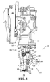
- FIG.4 shows a right side view of the wiper device when the needle bar is swung to the left;
- FIG.5 shows a perspective view of the wiper mechanism when the wiper member is in an inoperable state;
- FIG.6 shows a left side view of the wiper device when the needle bar is swung to the right;
- FIG.7 shows a front view of the wiper device when the needle bar is swung to the right;
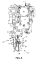
- FIG.8 shows a right side view of the wiper device when the needle bar is swung to the right;
- FIG.9 shows a perspective view of the wiper mechanism when the wiper member is in an operable state;
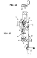
- FIG. 10 shows an enlarged view of the main part of the presser foot;
- FIG.11 shows a front view of the needle swing mechanism;
- FIG.12 is a front view of the needle swing mechanism when the needle bar is swung to the right;
- FIG. 13 shows a front view of the needle swing mechanism when the needle bar is swung to the left;
- FIG.14 shows the arrangement under the bed; and
- FIG. 15 is a block figure of the control system of the sewing machine.
- An embodiment of the present invention is described hereunder with reference to the drawings. A sewing machine M capable of embroidery sewing as shown in FIG.1 is explained herein under. This sewing machine M is a household electronically-controlled sewing machine as well known in the art and this sewing machine M is provided with a
bed 1, apillar 2 which stands on a right end of thebed 1, and anarm 3 extending over thebed 1 leftward from an upper end of thepillar 2. On a left end of thebed 1 is detachably attached an embroideryframe drive mechanism 4 for sewing embroidery using an embroidery frame (not shown). The embroideryframe drive mechanism 4 drives the embroidery frame to the X direction (lateral direction) and the Y direction (longitudinal direction) independently. - Below a needle plate 1a of the
bed 1 are provided a feed dog vertically moving mechanism (only thefeed dog 56 is shown) ; a feed dog laterally moving mechanism (only thefeed dog 56 is shown) ; a shuttle mechanism to detachably attach a bobbin on which a bobbin thread is wound; and a thread trimmer to trim the needle thread and bobbin thread, as shown in FIG. 14. Also, in the front surface of thepillar 2 is provided aliquid crystal display 6. - In the
arm 3 are provided a laterally extending sewing machine main shaft (not shown) rotationally driven by a sewing machine motor 68 (refer to FIG.15); a hand pulley 7 capable of rotating the sewing machine main axis with manual operation; and a needle bar drive mechanism (not shown) to vertically move aneedle bar 8 with a sewing needle attached in the lower end. In thearm 3 are also provided a needle swinging mechanism 9 (refer to FIG. 11) to swing theneedle bar 8 in a lateral direction perpendicular to the cloth feeding direction; a thread take-up lever drive mechanism (not shown); and a vertically moving mechanism (not shown) including a presser bar driving motor (stepping motor) 72 (refer to FIG. 15) fixed to the sewing machine frame and lifting apresser bar 10 between an elevated position and a lowered position, thepresser bar 10 being vertically moveably supported by the sewing machine frame. - In the front side of the
arm 3 is provided a sewing start/stop switch 11 to operate the starting and stopping of the sewing process. Awiper device 12 is provided on the head of thearm 3 to wipe off the needle thread so as to pull out the needle thread extending from the eye of thesewing needle 5 after trimming the needle thread by thethread trimmer 59 to the upper surface of the work cloth. Thewiper device 12 will be discussed in detail hereinafter. - Next, the control system of the sewing machine M will be described with reference to FIG. 15. The
control device 60 of sewing machine M is provided with a microcomputer including aCPU 61, aROM 62, and a RAM63; aninput interface 64; and anoutput interface 65. In theinput interface 64, a sewing start/stop switch 11, an operation panel 6a provided as a touch pad on the liquid crystal display, apotentiometer 66 and a phase angle sensor 67 are electrically connected. - A circular encoding disk is secured on a main shaft of the sewing machine. The encoding disk is formed with a plurality of small slits radially arranged at intervals of predetermined small angles is fixed and the phase angle sensor 67 made of a photo-interrupter outputs encoding signals for each reception of light passing through the slits, in response to the rotation of the sewing machine main shaft. The
control device 60 counts the pulse encoder signals to detect a phase angle of the sewing machine main shaft. However, it is assumed that the phase angle of the sewing machine main shaft is at 0 degrees when theneedle bar 8 is in the highest position. The count value is cleared when the phase angle is at 0 degrees. - To the
output interface 65 are electrically connected adrive circuit 69 for asewing machine motor 68, adrive circuit 71 for atrimming motor 70, and a drive circuit 73 for presserbar drive motor 72. To theoutput interface 65 are also connected a drive circuit 74 for a needle swing drive motor (stepping motor) 41 to drive theneedle swinging mechanism 9 and adrive circuit 76 for anX feed motor 75 provided in the embroideryframe drive mechanism 4 and drive circuit78 for aY feed motor 77 and adrive circuit 79 for aliquid crystal display 6 is electrically connected. - In the
ROM 62 are stored a utility pattern sewing data for a plurality of utility embroidery such as zigzag seams, a plurality types of embroidery data for embroidery sewing, drive control programs of various types to control the sewing machine M and a control program etc. for embroidery sewing control. In theRAM 63 are provided various types of memory, pointer and counter etc. to store the calculated results of the calculation processed in theCPU 61, based on necessity. - Next, the
wiper device 12 will be described. As shown in FIGS. 2 to 9, thewiper device 12 is provided with awiper mechanism 14 including awiper member 13 to wipe the thread, awiper driving unit 15 to generate the thread wiping movement of thewiper member 13 by driving thewiper mechanism 14 and a switch means 16 to switch thewiper member 13 between an operable state and an inoperable state in conjunction with position of theneedle bar 8. - Next the
wiper mechanism 14 andwiper member 13 are described in detail with reference to FIGS. 2 to 5. Thewiper mechanism 14 is configured by including awiper member 13, asupport member 17, asupport axis 27, a drive power input member and alink mechanism 20. - The
support member 17 is attached to the lower end of thepresser bar 10 with afastening screw 37 and on the lower end of thesupport member 17, apresser foot 26 is integrally formed. On thesupport member 17, a vertically pairedsupport 17a is provided, in which avertical support axis 27 fixed by being inserted therethrough is supported to extend in the upper direction. - A drive
power input member 19 is provided on thesupport member 17 via thesupport axis 27. The drivepower input member 19 is provided with amain body member 28 supported by thesupport shaft 27 and a contactingportion 29 pivotally attached in a laterally swingable manner to themain body member 28. - A pair of upper and lower guided
portions 28a are formed on themain body member 28. The lower guidedportion 28a is arranged in between a pair of upper andlower supports 17a and fitted with thesupport shaft 27 so as to be vertically slidable. The upper guidedportion 28a is arranged above theupper support 17a and fitted with thesupport shaft 27 so as to be vertically slidable. As a result, themain body member 28 is supported on thesupport shaft 27 so as to be vertically slidable. Further, anelastic member 30 configured by a compressed coil spring is attached to thesupport shaft 27 in between the support 27a on the upper end and the guidedportion 28a in the upper end. The drivepower input member 19 is biased upward by theelastic member 30. - A pair of front and
rear support pieces 28b are on the upper end of themain body member 28 so as to protrude rightward. Ahorizontal support shaft 31 is fixed between thesupport pieces 28b so as to be directed in a back-and-forth direction as viewed at the front. A contactingportion 29 is swingably and immovably supported on thehorizontal support axis 31. Also, the contactingportion 29 is biased counter-clockwise when viewed from the front by the elasticity of the twistedcoil spring 32 attached on the exterior ofhorizontal support axis 31. Furthermore, the contactingportion 29 can swing approximately 30 degrees clockwise from the locked state. - Next, the
wiper member 13 will be described. A horizontalpivotal support shaft 21 is fixed in parallel to the needle swing of theneedle bar 8 on themain body member 28 of the drivepower input member 19 and awiper member 13 is supported so as to be swingable and immovable in the axial direction. Thewiper member 13 is arranged to be installed to the support member 17 (having a presser foot 26) via the drivepower input member 19. Thewiper member 13 is provided with a circumventingarm 22 andthread wiper 23 integrally formed with the lower end of the circumventingarm 22. Thethread wiper 23 is formed in a crank when viewed from the front. On the end point of thethread wiper 23, aregulator 24 is provided and it keeps theneedle thread 10 which was wiped up from slipping off thethread wiper 13. The circumventingarm 22 is formed so as not to interfere with aneedle fastening member 25 affixing thesewing needle 5 to theneedle bar 8 on carrying out the thread wipe by the upward swing of thewiper member 13. - Next the
link mechanism 20 will be described. As shown in FIGS. 4, 5 and 8, thelink mechanism 20 includes adrive pin 33 inserted into and fixed to an approximately vertical center of thesupport shaft 27 in a direction parallel to the thread swinging direction of theneedle bar 8. Thelink mechanism 20 further includes aslit 34 cut out in an vertically elongated form on themain body member 28 of the drive power input member, a pair oflink arms 35 provided integrally on thewiper member 13, and alink 35a provided on thelink arms 35. Thisdrive pin 33 is slidingly engaged with both theslit 34 of the drivepower input member 19 and thelink 35a on thelink arms 35. - Next the operation of the
link mechanism 20 will be described. When the drivepower input member 19 is moved downward with the vertical position of thesupport member 17 mounted on thepresser bar 10 fixed in an immovable state, the position of the horizontalpivotal support shaft 21 is fixed on themain body member 28 of the drivepower input member 19 is moved downward with respect to thedrive pin 33. As a result, thelink 35a of thewiper member 13 in the disposition to extend diagonally downward towards the front as shown in FIG. 4 moves to the disposition to diagonally extend upward direction toward the front as shown in FIG. 8, as shown in FIG. 4, thethread wiper 23 of thewiper member 13 is moved from the rear of the needle thread extending from the needle eye (eye) to thepresser foot 26 in the lower portion to the position in front of theneedle fastening member 25 as shown in FIG. 8. - Next, the following describes the wiper drive means 15 to drive the
wiper member 13 by the vertical movement of thepresser bar 10. The wiper drive means 15 is configured by a vertically moving mechanism to vertically drive thepresser bar 10. Thepresser foot 26 is fixed on the lower end of thepresser bar 10 by thefastening screw 37. Thesupport member 17 integrally attached to thepresser foot 26 is vertically moved in the up-down direction by the vertical movement of thepresser bar 10. - The
needle bar platform 38 is in a form to vertically extend nearly in parallel to theneedle bar 8 and the upper end is supported by the sewing machine frame (refer to FIG.11) so as to be capable of swinging. In case thisneedle bar platform 38 is in a contactable position with the contactingportion 29 of the drivepower input member 19, the contactingportion 29 contacts theneedle bar platform 38 when thesupport member 17 is lifted along with the lift of thepresser bar 8. On and after the contactingportion 29 contacts theneedle bar platform 38, the contactingportion 29 is locked in that position. After that, when thesupport member 17 is further lifted along with thepresser bar 10, as described earlier, themain body member 28 of the drivepower input member 19 approaches thesupport member 17 to resist theelastic member 30 and the position of the horizontalpivotal support shaft 21 affixed on themain body member 28 is moved relatively downward against thedrive pin 33 of thelink mechanism 20. As a result, thewiper member 13 as shown in FIG. 4 is moved from the rear of the needle thread extending to the lower portion of the needle eye of thesewing needle 5 to the front of theneedle fastening member 25 as shown in FIG. 8, and wipes the thread as to pull out the needle thread to the needle thread of the work cloth. - By the movement of the
wiper member 13 as indicated in FIG. 4, from the rear of the needle thread extending to the lower portion of thepresser foot 26 from the needle eye (eye) of thesewing needle 5 of thewiper member 13 to the front side of theneedle fastening member 25 as shown in FIG. 8, wipes the thread as to pull out the needle thread residing in the lower surface of the work cloth via the eye to the upper surface of the work cloth. - As shown in FIG. 8, the wiped needle thread extends to the
regulator 24 of thewiper member 13 positioned in the front side of theneedle fastening member 25 via the eye. - As shown FIG. 10, the
ridge 36 of the eye of thepresser foot 26, is machined so that the needle thread can smoothly pass through even if the needle thread slides on theridge 36 of the eye of thepresser foot 26. - Next, the switching
unit 16 will be described. As shown in FIGS. 2 to 13, the switchingunit 16 is configured by thethread swing mechanism 9 and theneedle bar platform 38 to support theneedle bar 8 so as to be slidable in the vertical direction. - The
needle swinging mechanism 9 to swing theneedle bar 8 to the prescribed position is described. As shown in FIGS. 11 to 13, theneedle swinging mechanism 9 is provided with theneedle bar platform 38,swing lever 40, needleswing drive motor 41 andswing cam 42 etc. - As shown in FIG. 11, on the left surface of the
needle bar platform 38 having the upper end supported by the sewing machine frame so as to be swingable, an upper sidepivotal support 43 and lower sidepivotal support 44 are provided, and on these upper sidepivotal support 43 and lower sidepivotal support 44 theneedle bar 8 is vertically moveably supported. - The
swing lever 40 is formed to extend in a vertical direction nearly parallel to theneedle bar platform 38 and the approximate center of theswing lever 40 in the vertical direction is swingably pivoted by thepivot support pin 46 supported by the sewing machine frame. Thelower end 47 of theswing lever 40 is in contact with thecam 48 fixed in the lower end of the needle bar. Also, in the sewing machine frame, the needle swingingdrive motor 41 is fixed and on the rotating axis of the needle swinging drive motor, adrive gear 49 is provided. On the outer diameter of thedrive gear 49, a gear is formed and a swingingcam 42 supported rotatably on the sewing machine frame is fitted. On this swingingcam 42, acam surface 52 to laterally swing theneedle bar platform 38 is formed and on thiscam surface 52, apin 51 fixed on theupper end 55 of the swinginglever 40 is contacted. - The lower portion of the
needle bar platform 38 is biased leftward by the coil spring not shown and the contacting status of thelower end 47 and thecam body 48 and the contacting state of thepin 51 fixed on theupper end 55 and thecam surface 52 is retained. Thecam surface 52 formed on the swingingcam 42 is configured by a largeradius cam surface 53 spaced apart from the rotational center and a smallradius cam surface 54 less distanced from the rotational center and formed consecutively to the largeradius cam surface 53 is formed. - As indicated in FIG. 12, when the swinging
cam 42 rotates by the rotation of the needleswing drive motor 41 and thepin 51 contacts the largeradius cam surface 53 which is spaced apart from the rotational center of the swingingcam 42, theupper end 55 of the swinginglever 40 is moved leftward and thelower portion 47 of the swinginglever 40 is moved rightward via the pivotally supportedpin 46 to move theneedle bar platform 38 to the right direction. - As shown in FIG. 13, the swinging
cam 42 is rotated by theneedle swinging motor 41 and when thesmall cam surface 54 less distanced from the rotational center contacts thepin 51, theupper end 55 of the swinginglever 40 is moved in the left direction and in turn moves theneedle bar platform 38 to the left direction. - That is, by the
needle swinging mechanism 9, when thelower end 47 of the swinginglever 40 is moved to the right (refer FIG. 12) theneedle bar platform 38 is moved by theneedle swinging mechanism 9 to a position capable of contacting the contactingportion 29 of the drivepower input member 19. In this contactable position, when thesupport member 17 is lifted along with thepresser foot 26 caused by the vertical movement of thepresser bar 10, the contactingportion 29 contacts theneedle bar platform 38 to actuate thewiper member 13. - On the other hand, when the
lower portion 47 of the swinginglever 40 moves leftward (refer to FIG. 13) , theneedle bar platform 38 is moved to the non-contactable position. In this non-contactable position, even if thesupport member 17 is lifted along with thepresser foot 26 by the vertical movement of thepresser bar 10, because the contacting portion is positioned to the right side of theneedle bar platform 38 without contacting theneedle bar platform 38, thewiper member 13 is not actuated. - Next, the operational effect of the
wiper device 12 described above will be described. Thewiper device 12 is configured from awiper mechanism 14 including thewiper member 13 to perform the thread wiper, awiper driving unit 15 to generate the thread wiping movement of the wiper member by driving thewiper mechanism 14 and aswitch unit 16 to switch thewiper member 13 between the operable state and the inoperable state in conjunction with theneedle bar 8 with thesewing needle 5 in the lower end. Therefore, after the thread connecting the multiple embroidery areas in the process of embroidery formation is trimmed by thethread trimming unit 59, or after trimming the needle thread after changing the color of the embroidery thread and sew completion, the needle thread can be pulled out to the upper surface of the work cloth by actuating thewiper member 13 by thewiper driving unit 15. Also, by this switchingunit 16, the switching of thewiper member 13 state (operable and inoperable) is enabled by using theneedle swing mechanism 9 of theneedle bar 8. - The
wiper device 12 is mounted on thepresser bar 10 of the sewing machine main body with afastening screw 37 therefore the attachment and detachment can be easily performed. Also, because thewiper driving unit 15 is configured by the vertically moving mechanism to vertically move thepresser bar 10, a simple, low-cost and small-size configuration can be provided for actuating thewiper member 13. - The
wiper device 12 is configured by mounting thesupport member 17 provided with apresser foot 26 on thepresser bar 10, attaching the drivepower input member 19 to thesupport member 17 in a vertically moveable manner, providing anelastic member 30 to bias the drivepower input member 19 upward, pivotally supporting thewiper member 13 in a swingable manner to the drivepower input member 19 by the horizontalpivotal support shaft 21 placed in parallel with the needle swing direction and alink mechanism 20 to convert the relative descending movement of the drivepower input member 19 against thesupport member 17 to the swinging movement of thewiper member 13, therefore, thewiper member 13 can be actuated with a simple mechanism. - The switching
unit 16 is arranged so that when theneedle bar platform 38 is moved to the right position by theneedle swing mechanism 9, the contacting portion of the drivepower input member 19 contacts theneedle bar platform 38 and when theneedle bar platform 38 is in any other position, the contacting portion does not contact theneedle bar platform 38 therefore, thewiper member 13 can be reliably switched between the operable state and inoperable state. - The contacting
portion 29 of the drivepower input member 19 is swingably supported nearly in parallel with the swinging direction of theneedle bar platform 38. When theneedle bar platform 38 is moved to the right position, which is the operable position of thewiper member 13, from the inoperable state, which is the position other than the right position, after moving the contactingposition 29 to a position capable of contacting theneedle bar platform 38 by lifting thepresser bar 10, the contactingposition 29 is pressured by theneedle bar platform 38 and moved to the right, so as not to prevent the movement of theneedle bar platform 38. Thus the swinging of theneedle bar 8 in the prescribed range is not impaired by any limitations. - The
wiper member 13 is provided with a circumventingarm 22 so that at the time of performing the thread wipe, the wiper member does not interfere with theneedle fastening member 25 provided to fix the sewing needle to the needle bar and provide a smooth operation of the thread wipe. - Next, variations of the above embodiment incorporating partial changes will be described. In the present embodiment, the
wiper member 13 which is swingably pivotally supported on the drivepower input member 19 by the horizontalpivotal support shaft 21 placed in parallel with the needle swinging direction is swung in the longitudinal direction to perform the thread wipe, however, the thread wipe can be performed by pivotally supporting thewiper member 13 to swing in a direction parallel to the needle swinging direction. - The swingable arrangement of the contacting
portion 29 of the drivepower input member 19 can be arranged so that the contacted portion of theneedle bar platform 38 is swung and the contactingportion 29 is fixed.
Claims (8)
- A wiper device for a sewing machine comprising:a thread trimmer to trim a needle thread,a wiper member (13) to wipe the thread so as to pull out the needle thread extending from an eye of a sewing needle (5) after trimming the needle thread by the thread trimmer to the upper surface of work cloth,a wiper driving unit (15) to actuate a thread wiping operation of the wiper member (13), anda switch unit (16) to switch the wiper member (13) between an operable state and inoperable state in conjunction with a position of a needle bar (8).
- The wiper device according to claim 1, comprising a drive power input member (19) to actuate the thread wiping operation of the wiper member (13) by being pressed downward by the drive of the wiper driving unit (15).
- The wiper device according to claim 2, comprising a needle bar platform (38) vertically reciprocably supporting the needle bar (8) and a needle swinging mechanism (9) to swing the needle bar (8),
wherein the drive power input member (19) is provided with a contacting portion (29) contacting the needle bar platform (38), and the switch unit (16) is enable the contacting portion (29) to contact the needle bar platform (38) when in the operable state and to disable the contacting portion (29) to contact the needle bar platform (38) when in the inoperable state by swinging the needle bar (8) to a prescribed position by the needle swinging mechanism (9). - The wiper device according to one of claims 1 to 3 comprising a vertically moveable presser bar (10),wherein the wiper driving unit (15) is configured to drive the wiper member (13) by using the vertical movement of the presser bar (10).
- The wiper device according to one of claims 2 to 4, comprising a support member (17) which is mounted on the presser bar (10) and to which the drive power input member (19) is vertically moveably attached;
a presser foot (26) attached to the support member (17);
an elastic member (30) provided on the support member (17) to bias the drive power input member (19) upward,
wherein the wiper member (13) is pivotally supported in a swingable manner On the drive power input member by a horizontal pivotal support shaft (21) arranged in parallel to a needle swinging direction; and
a link mechanism (20) to convert a descent of the input drive power relative to the support member (17) to a swing of the wiper member (13): - The wiper device according to claim 5, wherein the contacting portion (29) of the drive power input member (19) is supported swingably substantially in parallel to the needle swing direction of the needle bar (8), and in a case where the needle bar platform (38) is swung to the position corresponding to the operable state after the presser bar (10) has been lifted to enable the contacting portion (29) to contact the needle bar platform (38) when the needle bar platform (38) is in the position corresponding to the inoperable state, the contacting portion (29) is swung along with the needle bar platform (38) so as not to prevent the swinging of the needle bar platform.
- The wiper device according to one of claims 1 to 6,
wherein the needle bar (8) is provided with a needle fastening member (25) to fix the sewing needle (5) and the wiper member (13) is provided with a circumventing arm (22) so as not to interfere with the needle fastening member (25) when performing the thread wipe. - The wiper device according to one of claims 1 to 7, comprising a presser bar (10) which is provided to be vertically moveable and to which a support member (17) having a lower end with a presser foot (26) is detachably attached,
wherein the needle bar (8) has a lower end on which the sewing needle (5) is mounted and the wiper member (13) is assembled to the presser foot (26) of the presser bar (10) so as to be swingable.
Applications Claiming Priority (1)
| Application Number | Priority Date | Filing Date | Title |
|---|---|---|---|
| JP2004200449A JP4507273B2 (en) | 2004-07-07 | 2004-07-07 | Sewing machine wiper equipment |
Publications (3)
| Publication Number | Publication Date |
|---|---|
| EP1614791A2 true EP1614791A2 (en) | 2006-01-11 |
| EP1614791A3 EP1614791A3 (en) | 2007-01-10 |
| EP1614791B1 EP1614791B1 (en) | 2008-09-17 |
Family
ID=34993120
Family Applications (1)
| Application Number | Title | Priority Date | Filing Date |
|---|---|---|---|
| EP05014675A Expired - Lifetime EP1614791B1 (en) | 2004-07-07 | 2005-07-06 | Wiper device for sewing machine |
Country Status (5)
| Country | Link |
|---|---|
| US (1) | US7093549B2 (en) |
| EP (1) | EP1614791B1 (en) |
| JP (1) | JP4507273B2 (en) |
| AT (1) | ATE408723T1 (en) |
| DE (1) | DE602005009767D1 (en) |
Cited By (1)
| Publication number | Priority date | Publication date | Assignee | Title |
|---|---|---|---|---|
| CN104878529A (en) * | 2015-04-11 | 2015-09-02 | 强信机械科技(莱州)有限公司 | Thread trimming and presser foot raising driving device of sewing machine |
Families Citing this family (6)
| Publication number | Priority date | Publication date | Assignee | Title |
|---|---|---|---|---|
| JP4492247B2 (en) * | 2004-08-03 | 2010-06-30 | ブラザー工業株式会社 | Embroiderable sewing machine |
| JP2007215734A (en) * | 2006-02-16 | 2007-08-30 | Brother Ind Ltd | sewing machine |
| JP2015168895A (en) | 2014-03-06 | 2015-09-28 | ブラザー工業株式会社 | sewing machine |
| JP2016063921A (en) * | 2014-09-24 | 2016-04-28 | ブラザー工業株式会社 | sewing machine |
| CN106637735B (en) * | 2016-12-07 | 2020-01-31 | 杰克缝纫机股份有限公司 | Thread trimming and presser foot lifter and sewing machine |
| CN109811480B (en) * | 2019-03-11 | 2020-11-27 | 浙江越隆缝制设备有限公司 | Multipoint feedback thread hooking device for embroidery machine |
Citations (2)
| Publication number | Priority date | Publication date | Assignee | Title |
|---|---|---|---|---|
| JPH0652782U (en) | 1992-12-22 | 1994-07-19 | ジューキ株式会社 | Sewing machine wiper device |
| JP2003103080A (en) | 2001-09-28 | 2003-04-08 | Brother Ind Ltd | sewing machine |
Family Cites Families (9)
| Publication number | Priority date | Publication date | Assignee | Title |
|---|---|---|---|---|
| US4370940A (en) * | 1981-03-12 | 1983-02-01 | Louisville Manufacturing Co., Inc. | Automatic thread trimmer for computerized zigzag embroidery sewing machine |
| JPH07100092B2 (en) * | 1986-08-12 | 1995-11-01 | ブラザー工業株式会社 | Sewing machine thread securing device |
| JPH01127580U (en) * | 1988-02-22 | 1989-08-31 | ||
| JPH0759268B2 (en) * | 1989-10-31 | 1995-06-28 | ブラザー工業株式会社 | Needle thread end holding device for sewing machine with thread trimming mechanism |
| DE4324741C2 (en) * | 1993-07-23 | 1996-01-25 | Pfaff Ag G M | Embroidery or sewing machine with a device for thread wiping |
| JP2833685B2 (en) * | 1993-11-20 | 1998-12-09 | ジューキ株式会社 | Sewing machine thread remover |
| JP2000116972A (en) * | 1998-10-15 | 2000-04-25 | Brother Ind Ltd | Sewing machine with button |
| US6568339B1 (en) * | 2000-06-28 | 2003-05-27 | Clinton Indusries, Inc. | Side mount thread wiper for a sewing machine |
| JP2003103081A (en) * | 2001-09-28 | 2003-04-08 | Barudan Co Ltd | sewing machine |
-
2004
- 2004-07-07 JP JP2004200449A patent/JP4507273B2/en not_active Expired - Fee Related
-
2005
- 2005-07-01 US US11/171,331 patent/US7093549B2/en not_active Expired - Lifetime
- 2005-07-06 DE DE602005009767T patent/DE602005009767D1/en not_active Expired - Lifetime
- 2005-07-06 EP EP05014675A patent/EP1614791B1/en not_active Expired - Lifetime
- 2005-07-06 AT AT05014675T patent/ATE408723T1/en not_active IP Right Cessation
Patent Citations (2)
| Publication number | Priority date | Publication date | Assignee | Title |
|---|---|---|---|---|
| JPH0652782U (en) | 1992-12-22 | 1994-07-19 | ジューキ株式会社 | Sewing machine wiper device |
| JP2003103080A (en) | 2001-09-28 | 2003-04-08 | Brother Ind Ltd | sewing machine |
Cited By (1)
| Publication number | Priority date | Publication date | Assignee | Title |
|---|---|---|---|---|
| CN104878529A (en) * | 2015-04-11 | 2015-09-02 | 强信机械科技(莱州)有限公司 | Thread trimming and presser foot raising driving device of sewing machine |
Also Published As
| Publication number | Publication date |
|---|---|
| EP1614791A3 (en) | 2007-01-10 |
| EP1614791B1 (en) | 2008-09-17 |
| JP2006020761A (en) | 2006-01-26 |
| US20060005753A1 (en) | 2006-01-12 |
| ATE408723T1 (en) | 2008-10-15 |
| US7093549B2 (en) | 2006-08-22 |
| DE602005009767D1 (en) | 2008-10-30 |
| JP4507273B2 (en) | 2010-07-21 |
Similar Documents
| Publication | Publication Date | Title |
|---|---|---|
| US20020062774A1 (en) | Sewing machine with a device for adjusting a pressure applied to a pressure bar and a device for lifting the presser bar | |
| CN113604986B (en) | Sewing machine | |
| US6067919A (en) | Needle threading device used in sewing machine | |
| EP1614791B1 (en) | Wiper device for sewing machine | |
| US7143706B2 (en) | Sewing machine with automatic needle threader | |
| US7280886B2 (en) | Sewing machine capable of embroidering | |
| US11255033B2 (en) | Presser foot vertical drive device and sewing machine including the same | |
| CN220413709U (en) | Needle feeding switching and presser foot driving mechanism of sewing machine | |
| JP4466800B2 (en) | Lower thread winding device of sewing machine | |
| JPH04156882A (en) | Fabric feed device for sewing machine | |
| JP4623423B2 (en) | Embroidery presser of embroidery sewing machine | |
| US7162965B2 (en) | Sewing machine | |
| US4370940A (en) | Automatic thread trimmer for computerized zigzag embroidery sewing machine | |
| JP2006020757A (en) | Embroidery sewing machine | |
| JP2003038872A (en) | Decorative sewing machine | |
| CN100591825C (en) | Upper thread clamping mechanism of sewing machine | |
| JP2546453B2 (en) | Sewing machine thread holding and holding device | |
| JP2000024353A (en) | sewing machine | |
| JPH07144083A (en) | Sewing machine thread wiper | |
| JPH09299643A (en) | sewing machine | |
| JP2568614Y2 (en) | Finger protection device for multi-needle sewing machine | |
| JP2006271525A (en) | Sewing machine wiper equipment | |
| JP2000271370A (en) | Multi-needle sewing machine | |
| JPH11276753A (en) | Embroidery sewing machine | |
| JP2000005469A (en) | Sewing equipment |
Legal Events
| Date | Code | Title | Description |
|---|---|---|---|
| PUAI | Public reference made under article 153(3) epc to a published international application that has entered the european phase |
Free format text: ORIGINAL CODE: 0009012 |
|
| 17P | Request for examination filed |
Effective date: 20050706 |
|
| AK | Designated contracting states |
Kind code of ref document: A2 Designated state(s): AT BE BG CH CY CZ DE DK EE ES FI FR GB GR HU IE IS IT LI LT LU LV MC NL PL PT RO SE SI SK TR |
|
| AX | Request for extension of the european patent |
Extension state: AL BA HR MK YU |
|
| PUAL | Search report despatched |
Free format text: ORIGINAL CODE: 0009013 |
|
| AK | Designated contracting states |
Kind code of ref document: A3 Designated state(s): AT BE BG CH CY CZ DE DK EE ES FI FR GB GR HU IE IS IT LI LT LU LV MC NL PL PT RO SE SI SK TR |
|
| AX | Request for extension of the european patent |
Extension state: AL BA HR MK YU |
|
| AKX | Designation fees paid |
Designated state(s): AT BE BG CH CY CZ DE DK EE ES FI FR GB GR HU IE IS IT LI LT LU LV MC NL PL PT RO SE SI SK TR |
|
| GRAP | Despatch of communication of intention to grant a patent |
Free format text: ORIGINAL CODE: EPIDOSNIGR1 |
|
| GRAS | Grant fee paid |
Free format text: ORIGINAL CODE: EPIDOSNIGR3 |
|
| GRAA | (expected) grant |
Free format text: ORIGINAL CODE: 0009210 |
|
| AK | Designated contracting states |
Kind code of ref document: B1 Designated state(s): AT BE BG CH CY CZ DE DK EE ES FI FR GB GR HU IE IS IT LI LT LU LV MC NL PL PT RO SE SI SK TR |
|
| REG | Reference to a national code |
Ref country code: GB Ref legal event code: FG4D |
|
| REG | Reference to a national code |
Ref country code: CH Ref legal event code: EP |
|
| REG | Reference to a national code |
Ref country code: IE Ref legal event code: FG4D |
|
| REF | Corresponds to: |
Ref document number: 602005009767 Country of ref document: DE Date of ref document: 20081030 Kind code of ref document: P |
|
| PG25 | Lapsed in a contracting state [announced via postgrant information from national office to epo] |
Ref country code: LT Free format text: LAPSE BECAUSE OF FAILURE TO SUBMIT A TRANSLATION OF THE DESCRIPTION OR TO PAY THE FEE WITHIN THE PRESCRIBED TIME-LIMIT Effective date: 20080917 |
|
| PG25 | Lapsed in a contracting state [announced via postgrant information from national office to epo] |
Ref country code: LV Free format text: LAPSE BECAUSE OF FAILURE TO SUBMIT A TRANSLATION OF THE DESCRIPTION OR TO PAY THE FEE WITHIN THE PRESCRIBED TIME-LIMIT Effective date: 20080917 Ref country code: FI Free format text: LAPSE BECAUSE OF FAILURE TO SUBMIT A TRANSLATION OF THE DESCRIPTION OR TO PAY THE FEE WITHIN THE PRESCRIBED TIME-LIMIT Effective date: 20080917 Ref country code: SI Free format text: LAPSE BECAUSE OF FAILURE TO SUBMIT A TRANSLATION OF THE DESCRIPTION OR TO PAY THE FEE WITHIN THE PRESCRIBED TIME-LIMIT Effective date: 20080917 Ref country code: AT Free format text: LAPSE BECAUSE OF FAILURE TO SUBMIT A TRANSLATION OF THE DESCRIPTION OR TO PAY THE FEE WITHIN THE PRESCRIBED TIME-LIMIT Effective date: 20080917 |
|
| NLV1 | Nl: lapsed or annulled due to failure to fulfill the requirements of art. 29p and 29m of the patents act | ||
| PG25 | Lapsed in a contracting state [announced via postgrant information from national office to epo] |
Ref country code: BE Free format text: LAPSE BECAUSE OF FAILURE TO SUBMIT A TRANSLATION OF THE DESCRIPTION OR TO PAY THE FEE WITHIN THE PRESCRIBED TIME-LIMIT Effective date: 20080917 |
|
| PG25 | Lapsed in a contracting state [announced via postgrant information from national office to epo] |
Ref country code: ES Free format text: LAPSE BECAUSE OF FAILURE TO SUBMIT A TRANSLATION OF THE DESCRIPTION OR TO PAY THE FEE WITHIN THE PRESCRIBED TIME-LIMIT Effective date: 20081228 Ref country code: BG Free format text: LAPSE BECAUSE OF FAILURE TO SUBMIT A TRANSLATION OF THE DESCRIPTION OR TO PAY THE FEE WITHIN THE PRESCRIBED TIME-LIMIT Effective date: 20081217 |
|
| PG25 | Lapsed in a contracting state [announced via postgrant information from national office to epo] |
Ref country code: RO Free format text: LAPSE BECAUSE OF FAILURE TO SUBMIT A TRANSLATION OF THE DESCRIPTION OR TO PAY THE FEE WITHIN THE PRESCRIBED TIME-LIMIT Effective date: 20080917 Ref country code: IS Free format text: LAPSE BECAUSE OF FAILURE TO SUBMIT A TRANSLATION OF THE DESCRIPTION OR TO PAY THE FEE WITHIN THE PRESCRIBED TIME-LIMIT Effective date: 20090117 Ref country code: NL Free format text: LAPSE BECAUSE OF FAILURE TO SUBMIT A TRANSLATION OF THE DESCRIPTION OR TO PAY THE FEE WITHIN THE PRESCRIBED TIME-LIMIT Effective date: 20080917 Ref country code: SK Free format text: LAPSE BECAUSE OF FAILURE TO SUBMIT A TRANSLATION OF THE DESCRIPTION OR TO PAY THE FEE WITHIN THE PRESCRIBED TIME-LIMIT Effective date: 20080917 Ref country code: CZ Free format text: LAPSE BECAUSE OF FAILURE TO SUBMIT A TRANSLATION OF THE DESCRIPTION OR TO PAY THE FEE WITHIN THE PRESCRIBED TIME-LIMIT Effective date: 20080917 Ref country code: PT Free format text: LAPSE BECAUSE OF FAILURE TO SUBMIT A TRANSLATION OF THE DESCRIPTION OR TO PAY THE FEE WITHIN THE PRESCRIBED TIME-LIMIT Effective date: 20090217 |
|
| PLBE | No opposition filed within time limit |
Free format text: ORIGINAL CODE: 0009261 |
|
| STAA | Information on the status of an ep patent application or granted ep patent |
Free format text: STATUS: NO OPPOSITION FILED WITHIN TIME LIMIT |
|
| PG25 | Lapsed in a contracting state [announced via postgrant information from national office to epo] |
Ref country code: EE Free format text: LAPSE BECAUSE OF FAILURE TO SUBMIT A TRANSLATION OF THE DESCRIPTION OR TO PAY THE FEE WITHIN THE PRESCRIBED TIME-LIMIT Effective date: 20080917 Ref country code: DK Free format text: LAPSE BECAUSE OF FAILURE TO SUBMIT A TRANSLATION OF THE DESCRIPTION OR TO PAY THE FEE WITHIN THE PRESCRIBED TIME-LIMIT Effective date: 20080917 |
|
| 26N | No opposition filed |
Effective date: 20090618 |
|
| PG25 | Lapsed in a contracting state [announced via postgrant information from national office to epo] |
Ref country code: IT Free format text: LAPSE BECAUSE OF FAILURE TO SUBMIT A TRANSLATION OF THE DESCRIPTION OR TO PAY THE FEE WITHIN THE PRESCRIBED TIME-LIMIT Effective date: 20080917 |
|
| PG25 | Lapsed in a contracting state [announced via postgrant information from national office to epo] |
Ref country code: SE Free format text: LAPSE BECAUSE OF FAILURE TO SUBMIT A TRANSLATION OF THE DESCRIPTION OR TO PAY THE FEE WITHIN THE PRESCRIBED TIME-LIMIT Effective date: 20081217 |
|
| PG25 | Lapsed in a contracting state [announced via postgrant information from national office to epo] |
Ref country code: MC Free format text: LAPSE BECAUSE OF NON-PAYMENT OF DUE FEES Effective date: 20090731 |
|
| REG | Reference to a national code |
Ref country code: CH Ref legal event code: PL |
|
| REG | Reference to a national code |
Ref country code: IE Ref legal event code: MM4A |
|
| PG25 | Lapsed in a contracting state [announced via postgrant information from national office to epo] |
Ref country code: LI Free format text: LAPSE BECAUSE OF NON-PAYMENT OF DUE FEES Effective date: 20090731 Ref country code: CH Free format text: LAPSE BECAUSE OF NON-PAYMENT OF DUE FEES Effective date: 20090731 |
|
| PG25 | Lapsed in a contracting state [announced via postgrant information from national office to epo] |
Ref country code: PL Free format text: LAPSE BECAUSE OF FAILURE TO SUBMIT A TRANSLATION OF THE DESCRIPTION OR TO PAY THE FEE WITHIN THE PRESCRIBED TIME-LIMIT Effective date: 20080917 |
|
| PG25 | Lapsed in a contracting state [announced via postgrant information from national office to epo] |
Ref country code: IE Free format text: LAPSE BECAUSE OF NON-PAYMENT OF DUE FEES Effective date: 20090706 |
|
| PG25 | Lapsed in a contracting state [announced via postgrant information from national office to epo] |
Ref country code: GR Free format text: LAPSE BECAUSE OF FAILURE TO SUBMIT A TRANSLATION OF THE DESCRIPTION OR TO PAY THE FEE WITHIN THE PRESCRIBED TIME-LIMIT Effective date: 20081218 |
|
| PG25 | Lapsed in a contracting state [announced via postgrant information from national office to epo] |
Ref country code: LU Free format text: LAPSE BECAUSE OF NON-PAYMENT OF DUE FEES Effective date: 20090706 |
|
| PG25 | Lapsed in a contracting state [announced via postgrant information from national office to epo] |
Ref country code: HU Free format text: LAPSE BECAUSE OF FAILURE TO SUBMIT A TRANSLATION OF THE DESCRIPTION OR TO PAY THE FEE WITHIN THE PRESCRIBED TIME-LIMIT Effective date: 20090318 |
|
| PG25 | Lapsed in a contracting state [announced via postgrant information from national office to epo] |
Ref country code: TR Free format text: LAPSE BECAUSE OF FAILURE TO SUBMIT A TRANSLATION OF THE DESCRIPTION OR TO PAY THE FEE WITHIN THE PRESCRIBED TIME-LIMIT Effective date: 20080917 |
|
| PGFP | Annual fee paid to national office [announced via postgrant information from national office to epo] |
Ref country code: GB Payment date: 20110622 Year of fee payment: 7 |
|
| PG25 | Lapsed in a contracting state [announced via postgrant information from national office to epo] |
Ref country code: CY Free format text: LAPSE BECAUSE OF FAILURE TO SUBMIT A TRANSLATION OF THE DESCRIPTION OR TO PAY THE FEE WITHIN THE PRESCRIBED TIME-LIMIT Effective date: 20080917 |
|
| PGFP | Annual fee paid to national office [announced via postgrant information from national office to epo] |
Ref country code: FR Payment date: 20110727 Year of fee payment: 7 |
|
| PGFP | Annual fee paid to national office [announced via postgrant information from national office to epo] |
Ref country code: DE Payment date: 20110729 Year of fee payment: 7 |
|
| GBPC | Gb: european patent ceased through non-payment of renewal fee |
Effective date: 20120706 |
|
| REG | Reference to a national code |
Ref country code: FR Ref legal event code: ST Effective date: 20130329 |
|
| PG25 | Lapsed in a contracting state [announced via postgrant information from national office to epo] |
Ref country code: GB Free format text: LAPSE BECAUSE OF NON-PAYMENT OF DUE FEES Effective date: 20120706 Ref country code: FR Free format text: LAPSE BECAUSE OF NON-PAYMENT OF DUE FEES Effective date: 20120731 Ref country code: DE Free format text: LAPSE BECAUSE OF NON-PAYMENT OF DUE FEES Effective date: 20130201 |
|
| REG | Reference to a national code |
Ref country code: DE Ref legal event code: R119 Ref document number: 602005009767 Country of ref document: DE Effective date: 20130201 |