EP1614570A2 - Open roof construction for a vehicle - Google Patents
Open roof construction for a vehicle Download PDFInfo
- Publication number
- EP1614570A2 EP1614570A2 EP05109291A EP05109291A EP1614570A2 EP 1614570 A2 EP1614570 A2 EP 1614570A2 EP 05109291 A EP05109291 A EP 05109291A EP 05109291 A EP05109291 A EP 05109291A EP 1614570 A2 EP1614570 A2 EP 1614570A2
- Authority
- EP
- European Patent Office
- Prior art keywords
- closure means
- slide
- roof construction
- guide
- link member
- Prior art date
- Legal status (The legal status is an assumption and is not a legal conclusion. Google has not performed a legal analysis and makes no representation as to the accuracy of the status listed.)
- Granted
Links
Images


Classifications
-
- B—PERFORMING OPERATIONS; TRANSPORTING
- B60—VEHICLES IN GENERAL
- B60J—WINDOWS, WINDSCREENS, NON-FIXED ROOFS, DOORS, OR SIMILAR DEVICES FOR VEHICLES; REMOVABLE EXTERNAL PROTECTIVE COVERINGS SPECIALLY ADAPTED FOR VEHICLES
- B60J7/00—Non-fixed roofs; Roofs with movable panels, e.g. rotary sunroofs
- B60J7/02—Non-fixed roofs; Roofs with movable panels, e.g. rotary sunroofs of sliding type, e.g. comprising guide shoes
- B60J7/04—Non-fixed roofs; Roofs with movable panels, e.g. rotary sunroofs of sliding type, e.g. comprising guide shoes with rigid plate-like element or elements, e.g. open roofs with harmonica-type folding rigid panels
- B60J7/043—Sunroofs e.g. sliding above the roof
- B60J7/0435—Sunroofs e.g. sliding above the roof pivoting upwardly to vent mode and moving at the outside of the roof to fully open mode
Definitions
- the invention relates to a novel open roof construction for a vehicle of the type known from, for example, EP-A-0296644 or US-A-4995667.
- Such a known open roof construction for a vehicle is provided with a roof opening defined in a fixed roof construction of the vehicle, and a panel-shaped closure means for the roof opening movable between a closing position for closing said roof opening and an opening position for at least partially exposing said roof opening, said closure means having a forward edge and a rearward edge, wherein during transition of the closure means from one of said positions towards the other of said positions at least one of said forward and rearward edges of the closure means also is moved in a direction towards or away from, respectively, the fixed roof construction, and wherein a guide mechanism is provided for the movement of at least one of said edges of the closure means, said guide mechanism comprising:
- Figure 1 shows an embodiment of a first guide mechanism in a first position thereof
- FIG. 10 there is schematically shown a vehicle 1 with a fixed roof construction 2.
- a roof opening 3 is defined in the fixed roof construction 2 and a panel-shaped closure means 4 is provided which is movable between a closing position 4 (indicated in full lines) for closing said roof opening 3 and an opening position 4" (indicated in chain dotted lines) for at least partially exposing said roof opening 3.
- the closure means 4 While moving from the closing position toward the opening position, the closure means 4 firstly reaches a position 4'(indicated in dotted lines) and then moves towards the opening position 4".
- the closure means 4 has a forward edge 5 and a rearward edge 6 (as seen in the longitudinal direction of the vehicle 1) which each co-operate with a stationary guiding 7 by means of forward and rearward, respectively, means 8 and 9. It is noted, that the position of the closure means, stationary guiding 7 and forward and rearward means 8 and 9 is only schematically indicated in figure 10. Further one can see, that in the opening position of the closure means 4" the forward means 8 has reached a new position 8'. The same applies for the rearward means 9 but this has not been indicated in this figure.
- a drive member 10 for example an electric motor
- a drive means 11 for a example a Bowden cable
- the stationary guiding 7 is attached to the fixed roof construction 2 of the vehicle 1 and extends basically in the longitudinal direction of the vehicle.
- a slide 12 (shown in a hatched manner) engages the guiding 7 and is driven by the drive means 11 for a guided movement along the guiding 7.
- the slide 12 is provided with a curved track 13 comprising a first part 14 extending substantially in parallel to the direction of movement of the slide 12 along the stationary guiding 7, and an arc-shaped second part 15 diverging therefrom towards the closure means 4.
- a link member 16 having a first end 17 that hingeably 18 engages an arm 19 attached to the closure means 4.
- the link member 16 further has an opposite second end 20 to which is rotatably attached a first link member guide 21 (e.g. a slide block).
- a second link member guide 22 e.g. a slide pin is also attached to the opposite second end 20 of the link member 16.
- the stationary guiding 7 comprises a first link member guide track 23 that houses the first link member guide 21 of the link member 16. Further, the stationary guiding 7 comprises a second link member guide track 24, 24' which has a first section 24 extending in parallel to the first link member guide track 23, and an arc-shaped second section 24' extending transversely thereto.
- the second link member guide 22 co-operates with said second link member guide track 24, 24' in a manner to be described later.
- first link member guide 21 and second link member guide 22 are spaced apart some distance.
- the end of the first link member guide track 23 defines a stop 25 limiting the extreme position of the first link member guide 21.
- the link member 16 further is provided with a coupling pin 26 positioned somewhere between its first end 17 and opposite second end 20. This coupling pin 26 is housed within the curved track 13 of the slide 12.
- the slide 12 also is provided with a hook member 27 which, in a manner to be described later, can engage a co-operating part 28 of the link member 16. Further the slide 12 is provided with a locking member shaped as a hook 29 for locking a pin 30 attached to the closure means 4 when the latter is in its closing position as illustrated in figure 1.
- the rearward guide mechanism operates in the following manner: starting from the closing position of the closure means 4 illustrated in figure 1, an activation of the drive means 11 by means of the drive member 10 will move the slide 12 to the left. During this motion the coupling pin 26 of the link member 16 firstly moves through the first part 14 of the curved track 13. Meanwhile the locking member 29 will disengage the pin 30 of the closure means 4. During this first stage of the movement of the slide 12 the link member 16 will maintain its position as shown in figure 1, in which its first link member guide 21 rests against the stop 25, while its second link member guide 22 is positioned at the end of the arc-shaped second section 24' of the second link member guide track.
- first link member guide 21 and the second link member guide 22 of the link member 16 will co-operate with the respective first link member guide track 23 and second link member guide track 24, such that a rotation of the link member 16 will be prevented.
- FIG 4 a position of the closure means 4 is shown which basically corresponds with its opening position.
- the rearward edge 6 of the closure means 4 nearly has reached a forward edge 32 of the roof opening 3.
- the link member 16 still is in its rotated position.
- the co-operating part 28 of the link member 16 is completely engaged by the hook member 27 of the slide 12.
- the closure means 4 When starting from the opening position illustrated in fig. 4, the closure means 4 has to be moved to the closing position illustrated in fig. 1, the slide 12 is moved to the right by the drive member 10 and drive means 11. Because a rotation of the link member 16 is not yet possible, the coupling pin 26 will maintain its position relative to the arc-shaped second part 15 of the curved track 16 of the slide 12. Thus the link member 16, and therefore the closure means 4, are moved along with the slide 12 to the right.
- a stationary guide track 33 which is attached to the fixed roof construction 2 in a manner not shown in detail, comprises a first section 34 which forwardly extends substantially in parallel to the stationary guiding 7 and which backwardly merges into a second section 35 extending transversely thereto in the direction of the fixed roof construction 2 or stationary guiding 7. It is noted, that in the figures only the first part of the first section 34 is illustrated; this first section 34 will extend further to the left along teh fixed roof construction 2.
- a first guide pin 36 is, in a manner not shown in detail, attached to the closure means 4 and, in the closing position of the closure means 4, is positioned at the end of the second section 35 of the stationary guide track 33.
- the guide mechanism for the forward edge 5 further comprises a latching member 37 that can move along the stationary guiding 7.
- This latching member 37 comprises a latching track 38, 38' with a first part 38 substantially in parallel with the stationary guiding 7 and a second part 38' diverging backwardly therefrom towards the closure means 4.
- the closure means 4 comprises a second guide pin 39 to be engaged by the latching track 38, 38', and housed in the first part 38 thereof when the closure means 4 is in its closing position.
- the latching member 37 is connected with the slide 12 for at least temporarily moving therewith along the stationary guiding 7.
- a connection may be realised by means of a flexible cable 40, such as for example a Bowden cable.
- the latching member 37 has moved to the left to such an extent, that the second guide pin 39 has followed the first part 38 and next the second part 38' of the latching track and has left this latching track.
- the forward edge 5 of the closure means 4 has been raised, such that the first guide pin 36 of the closure means 4 is moved upwardly in the second section 35 of the stationary guide track 33.
- This position of the forward edge 5 of the closure means 4 basically corresponds with the position of the rearward edge 6 as illustrated in fig. 3.
- the closure means 4 is free to move to the left, as explained before in relation to the guide mechanism for the rearward edge 6, whereby the first guide pin 36 moves further towards the first section 34 of the stationary guide track 33 (fig. 7).
- the first guide pin 36 of the closure means 4 will follow the first section 34 of the stationary guide track 33 until the closure means 4 has reached its opening position (for example as shown in fig. 4, in which the rearward edge 6 is near to the forward edge 32 of the roof opening 3) .
- the slide 12 is shown in a hatched manner. Further a frame 41 (schematically indicated by double lines) of a coupling member is shown. In a manner not shown in detail this frame or coupling member 41 is movable along the stationary guiding 7 (see fig. 9).
- the frame 41 of the coupling member carries a pivot arm 42 (indicated in dotted lines) having a pivot axis 43.
- a free end 44 of the pivot arm 42 is provided with a guide projection 45 co-operating with a curved track 46 defined in the stationary guiding 7.
- the pivot arm 42 comprises an engagement member 47 which, in the embodiment shown and as illustrated in figure 8, coincides with the guide projection 45.
- the slide 12 is provided with a projection 48 which can engage the engagement member 47 of the pivot arm 42 when the pivot arm 42 is in the position as shown in figure 8 and as defined by the curved track 46.
- the projection 48 pushes against the engagement member 47 and thus takes the pivot arm 42 and the frame 41 of the coupling member also to the left.
- the pivot arm 42 is provided with a recess 50 which, in the pivot position illustrated in fig. 9, co-operates with a projection 51 of the stationary guiding 7.
- the co-operation between the recess 50 and projection 51 defines and maintains the position of the coupling member.
- pivot arm 42 is spring loaded towards its second pivot position by means of a spring member 52.
- connection between the coupling member (frame 41) and the latching member 37 may be realised by the flexible cable 40, as indicated before.
- the slide 12 further is provided with an abutment means 49.
- this abutment means 49 will engage a coupling member, for example the abutment means 53 thereof, and thus moves the coupling means along to the right.
- the pivot arm 42 due to the co-operation between the guide projection 45 and the curved track 46, will pivot to its pivot position as illustrated in fig. 8, in which the engagement member 47 of the pivot arm 42 is again in a position to be engaged by the projection 48 of the slide 12.
- the latching member 37 of the guide mechanism of the forward edge 5 of the closure means 4 is connected to the slide 12 in such a manner, that the latching member 37 only moves together with the slide 12 until the second guide pin 39 (fig. 5) has moved out of the latching track 38, 38' of the latching member 37.
- the situation illustrated in fig. 9 basically corresponds with the situation illustrated in fig. 6.
- the coupling member described before also could be provided between another pair of parts of an open roof construction, which are movable along a stationary guiding 7.
Abstract
Description
- The invention relates to a novel open roof construction for a vehicle of the type known from, for example, EP-A-0296644 or US-A-4995667.
- Such a known open roof construction for a vehicle is provided with a roof opening defined in a fixed roof construction of the vehicle, and a panel-shaped closure means for the roof opening movable between a closing position for closing said roof opening and an opening position for at least partially exposing said roof opening, said closure means having a forward edge and a rearward edge, wherein during transition of the closure means from one of said positions towards the other of said positions at least one of said forward and rearward edges of the closure means also is moved in a direction towards or away from, respectively, the fixed roof construction, and wherein a guide mechanism is provided for the movement of at least one of said edges of the closure means, said guide mechanism comprising:
- a stationary guiding attached to the fixed roof construction and extending in the longitudinal direction of the vehicle;
- a slide engaging the guiding and being driven by a drive means for a guided movement along the guiding;
- a link member having a first end that hingeably engages the closure means and an opposite second end that slidingly and hingeably engages the stationary guiding,
- It is an object of the present invention to further improve such an open roof construction for a vehicle.
- The characteristic features of the open roof construction in accordance with the present invention are defined in the
independent claim 1. - By means of such an open roof construction the movement of the closure means is realised in an effective manner.
- Preferred embodiments of the open roof construction according to the present invention are described in the depending subclaims.
- Hereinafter the invention will be elucidated while referring to the drawing, in which an embodiment of the open roof construction according to the invention is illustrated.
- Figure 1 shows an embodiment of a first guide mechanism in a first position thereof;
- figure 2 shows the same guide mechanism in a second position thereof;
- figure 3 shows the same guide mechanism in a third position thereof;
- figure 4 shows the same guide mechanism in a fourth position thereof;
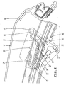
- figure 5 shows a second guide mechanism in a first position thereof;
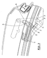
- figure 6 shows said second guide mechanism in a second position thereof;
- figure 7 shows said second guide mechanism in a third position thereof;
- figure 8 shows, schematically, an embodiment of a coupling member in a first position thereof;
- figure 9 shows said coupling member in a second position thereof, and
- figure 10 shows, schematically, part of a vehicle provided with an open roof construction in accordance with the present invention.
- Firstly referring tot figure 10 there is schematically shown a
vehicle 1 with a fixedroof construction 2. Aroof opening 3 is defined in the fixedroof construction 2 and a panel-shaped closure means 4 is provided which is movable between a closing position 4 (indicated in full lines) for closing saidroof opening 3 and anopening position 4" (indicated in chain dotted lines) for at least partially exposing saidroof opening 3. While moving from the closing position toward the opening position, the closure means 4 firstly reaches a position 4'(indicated in dotted lines) and then moves towards theopening position 4". - The closure means 4 has a
forward edge 5 and a rearward edge 6 (as seen in the longitudinal direction of the vehicle 1) which each co-operate with a stationary guiding 7 by means of forward and rearward, respectively, means 8 and 9. It is noted, that the position of the closure means, stationary guiding 7 and forward and rearwardmeans forward means 8 has reached a new position 8'. The same applies for the rearwardmeans 9 but this has not been indicated in this figure. - In the embodiment shown in figure 10 a drive member 10 (for example an electric motor) is shown connected to the rearward
means 9 through a drive means 11 (for a example a Bowden cable) for operating the open roof construction. - For explaining the guide mechanism of the
rearward edge 6 of the closure means 4, now reference is made to figures 1-4 illustrating successive positions of such a guide mechanism. - Firstly referring to figure 1, the most rearward section of the stationary guiding 7 together with the
rearward edge 6 of the closure means 4 are illustrated. As indicated before, thestationary guiding 7 is attached to thefixed roof construction 2 of thevehicle 1 and extends basically in the longitudinal direction of the vehicle. A slide 12 (shown in a hatched manner) engages the guiding 7 and is driven by the drive means 11 for a guided movement along the guiding 7. Theslide 12 is provided with acurved track 13 comprising afirst part 14 extending substantially in parallel to the direction of movement of theslide 12 along the stationary guiding 7, and an arc-shapedsecond part 15 diverging therefrom towards the closure means 4. - Further, there is provided a
link member 16 having afirst end 17 that hingeably 18 engages anarm 19 attached to the closure means 4. Thelink member 16 further has an oppositesecond end 20 to which is rotatably attached a first link member guide 21 (e.g. a slide block). A second link member guide 22 (e.g. a slide pin) is also attached to the oppositesecond end 20 of thelink member 16. - The stationary guiding 7 comprises a first link
member guide track 23 that houses the firstlink member guide 21 of thelink member 16. Further, the stationary guiding 7 comprises a second linkmember guide track 24, 24' which has afirst section 24 extending in parallel to the first linkmember guide track 23, and an arc-shaped second section 24' extending transversely thereto. The secondlink member guide 22 co-operates with said second linkmember guide track 24, 24' in a manner to be described later. - As can be seen in figure 1, the first
link member guide 21 and secondlink member guide 22 are spaced apart some distance. - The end of the first link
member guide track 23 defines astop 25 limiting the extreme position of the firstlink member guide 21. - The
link member 16 further is provided with acoupling pin 26 positioned somewhere between itsfirst end 17 and oppositesecond end 20. Thiscoupling pin 26 is housed within thecurved track 13 of theslide 12. - The
slide 12 also is provided with ahook member 27 which, in a manner to be described later, can engage aco-operating part 28 of thelink member 16. Further theslide 12 is provided with a locking member shaped as ahook 29 for locking apin 30 attached to the closure means 4 when the latter is in its closing position as illustrated in figure 1. - The rearward guide mechanism operates in the following manner: starting from the closing position of the closure means 4 illustrated in figure 1, an activation of the drive means 11 by means of the
drive member 10 will move theslide 12 to the left. During this motion thecoupling pin 26 of thelink member 16 firstly moves through thefirst part 14 of thecurved track 13. Meanwhile thelocking member 29 will disengage thepin 30 of the closure means 4. During this first stage of the movement of theslide 12 thelink member 16 will maintain its position as shown in figure 1, in which its firstlink member guide 21 rests against thestop 25, while its secondlink member guide 22 is positioned at the end of the arc-shaped second section 24' of the second link member guide track. - When the
slide 12 has moved to the left (as seen in figure 1) sufficiently, thecoupling pin 26 of thelink member 16 reaches the arc-shapedsecond part 15 of thecurved track 13 of theslide 12, and thus a rotation of thelink member 16 will occur. This rotation is enabled by an axis ofrotation 31 between thelink member 16 and its firstlink member guide 21. During this rotation of thelink member 16 the secondlink member guide 22 moves through the arc-shaped second section 24' of the second link member guide track. As long as the secondlink member guide 22 is within the arc-shapedsecond section 24" the firstlink member guide 21 will not move in the first linkmember guide track 23. - As a result of the rotation of the
link member 16, itsfirst end 17 withhingeable connection 18 to the closure means 4 will move away from the fixed roof construction or stationary guiding 7, and as a result therearward edge 6 of the closure means 4 will move in a direction away from the fixed roof construction (or stationary guiding 7). It is noted that during this movement of the closure means 4 it also will move slightly in a forward direction (to the left as seen in fig. 2). - Such a movement of the closure means 4 away from the fixed
roof construction 2 is allowed, because thelocking member 29 has completely disengaged thepin 30 of the closure means 4. When theslide 12 has moved still further to the left (fig. 3) thelink member 16 is rotated that far, that its secondlink member guide 22 has reached the connection between thefirst section 24 and the arc-shaped second section 24' of the second link member guide track. At this moment thehook member 27 of theslide 12 starts to engage theco-operating part 28 of the link member 16 (which in the embodiment illustrated is part of the first link member guide 21) and thus will entrain thelink member 16. A movement of thelink member 16 to the left (as seen in fig. 3) now is possible, because the secondlink member guide 22 has left the arc-shaped second section 24' of the second link member guide track. During such a movement of thelink member 16 to the left its firstlink member guide 21 will move to the left in the first linkmember guide track 23, whereas its secondlink member guide 22 will move to the left in thefirst section 24 of the second link member guide track. As a result of such a movement, the closure means 4 also will be moved to the left. Basically, the rotational position of thelink member 16 will not change anymore during such a movement to the left. - It is noted, that during the further movement of the guide mechanism to the left, the first
link member guide 21 and the secondlink member guide 22 of thelink member 16 will co-operate with the respective first linkmember guide track 23 and second linkmember guide track 24, such that a rotation of thelink member 16 will be prevented. - In figure 4 a position of the closure means 4 is shown which basically corresponds with its opening position. The
rearward edge 6 of the closure means 4 nearly has reached a forward edge 32 of theroof opening 3. As can be seen, thelink member 16 still is in its rotated position. Theco-operating part 28 of thelink member 16 is completely engaged by thehook member 27 of theslide 12. - When starting from the opening position illustrated in fig. 4, the closure means 4 has to be moved to the closing position illustrated in fig. 1, the
slide 12 is moved to the right by thedrive member 10 and drive means 11. Because a rotation of thelink member 16 is not yet possible, thecoupling pin 26 will maintain its position relative to the arc-shapedsecond part 15 of thecurved track 16 of theslide 12. Thus thelink member 16, and therefore the closure means 4, are moved along with theslide 12 to the right. - When the
slide 12 has moved to the right sufficiently far, the firstlink member guide 21 will engage thestop 25, at which moment the secondlink member guide 22 has reached the connection between thefirst section 24 and arc-shaped second section 24' of the second link member guide track (figure 3). Then, a rotation of thelink member 16 will occur, during which thecoupling pin 26 will move along the arc-shapedsecond part 15 towards thefirst part 14 of thecurved track 13, while the secondlink member guide 22 moves into the arc-shaped second section 24' of the second link member guide track. As a result the closure means 4 moves towards the fixedroof construction 2. When the secondlink member guide 22 has reached the end of the arc-shaped second section 24' of the second link member guide track the lockingmember 29 will engage thepin 30 and will firmly pull the closure means 4 against the fixedroof construction 2. - Next a guide mechanism provided for the movement of the
forward edge 5 of the closure means 4 will be discussed while referring to figures 5-7. - In fig. 5 the
forward edge 5 of the closure means 4 is in a position (closing position of the closure means 4) which basically corresponds with the position of therearward edge 6 illustrated in fig. 1. Astationary guide track 33, which is attached to the fixedroof construction 2 in a manner not shown in detail, comprises afirst section 34 which forwardly extends substantially in parallel to thestationary guiding 7 and which backwardly merges into asecond section 35 extending transversely thereto in the direction of the fixedroof construction 2 orstationary guiding 7. It is noted, that in the figures only the first part of thefirst section 34 is illustrated; thisfirst section 34 will extend further to the left along teh fixedroof construction 2. Afirst guide pin 36 is, in a manner not shown in detail, attached to the closure means 4 and, in the closing position of the closure means 4, is positioned at the end of thesecond section 35 of thestationary guide track 33. - The guide mechanism for the
forward edge 5 further comprises a latchingmember 37 that can move along thestationary guiding 7. This latchingmember 37 comprises a latchingtrack 38, 38' with afirst part 38 substantially in parallel with thestationary guiding 7 and a second part 38' diverging backwardly therefrom towards the closure means 4. The closure means 4 comprises asecond guide pin 39 to be engaged by the latchingtrack 38, 38', and housed in thefirst part 38 thereof when the closure means 4 is in its closing position. - In a manner to be described later, the latching
member 37 is connected with theslide 12 for at least temporarily moving therewith along thestationary guiding 7. Such a connection may be realised by means of aflexible cable 40, such as for example a Bowden cable. - Referring to fig. 6, the latching
member 37 has moved to the left to such an extent, that thesecond guide pin 39 has followed thefirst part 38 and next the second part 38' of the latching track and has left this latching track. As a result theforward edge 5 of the closure means 4 has been raised, such that thefirst guide pin 36 of the closure means 4 is moved upwardly in thesecond section 35 of thestationary guide track 33. This position of theforward edge 5 of the closure means 4 basically corresponds with the position of therearward edge 6 as illustrated in fig. 3. - Because now the latching
member 37 has disengaged thesecond guide pin 39 of the closure means 4, the closure means 4 is free to move to the left, as explained before in relation to the guide mechanism for therearward edge 6, whereby thefirst guide pin 36 moves further towards thefirst section 34 of the stationary guide track 33 (fig. 7). During a further movement of the closure means 4 to the left (forward direction of the vehicle 1) thefirst guide pin 36 of the closure means 4 will follow thefirst section 34 of thestationary guide track 33 until the closure means 4 has reached its opening position (for example as shown in fig. 4, in which therearward edge 6 is near to the forward edge 32 of the roof opening 3) . - After the latching
member 37 has disengaged thesecond guide pin 39 as illustrated in fig. 6, a further movement of the latchingmember 37 is no longer necessary. The connection between the latchingmember 37 and theslide 12 therefore is such, that the latchingmember 37 only temporarily moves along with theslide 12, as indicated before. A mechanism for realising such a temporarily common motion between the latchingmember 37 and theslide 12 will now be explained while referring to figures 8 and 9. - Referring to fig. 8, the
slide 12 is shown in a hatched manner. Further a frame 41 (schematically indicated by double lines) of a coupling member is shown. In a manner not shown in detail this frame or couplingmember 41 is movable along the stationary guiding 7 (see fig. 9). Theframe 41 of the coupling member carries a pivot arm 42 (indicated in dotted lines) having apivot axis 43. A free end 44 of thepivot arm 42 is provided with a guide projection 45 co-operating with a curved track 46 defined in thestationary guiding 7. Further, thepivot arm 42 comprises an engagement member 47 which, in the embodiment shown and as illustrated in figure 8, coincides with the guide projection 45. - The
slide 12 is provided with aprojection 48 which can engage the engagement member 47 of thepivot arm 42 when thepivot arm 42 is in the position as shown in figure 8 and as defined by the curved track 46. Thus, when theslide 12 moves to the left, theprojection 48 pushes against the engagement member 47 and thus takes thepivot arm 42 and theframe 41 of the coupling member also to the left. - While moving to the left, the guide projection 45 follows the curved track 46 and will reach the position as shown in fig. 9. In this position, the
pivot arm 42 has pivoted downwardly, such that the engagement member 47 no longer engages theprojection 48 of the slide 12 (slide 12 is not indicated in fig. 9, only itsprojection 48 and an abutment means 49 to be described later). - When the
pivot arm 42 has reached the position as illustrated in fig. 9, a further movement of theslide 12 to the left will not lead anymore to a corresponding movement of the coupling member to the left. Thus, the coupling member then maintains its position. - The
pivot arm 42 is provided with a recess 50 which, in the pivot position illustrated in fig. 9, co-operates with a projection 51 of thestationary guiding 7. The co-operation between the recess 50 and projection 51 defines and maintains the position of the coupling member. - For securely maintaining this position of the
pivot arm 42, it is possible that thepivot arm 42 is spring loaded towards its second pivot position by means of a spring member 52. - The connection between the coupling member (frame 41) and the latching
member 37 may be realised by theflexible cable 40, as indicated before. An additional abutment means 53 attached to theframe 41 engages thepivot arm 42, thus ensuring an effective transfer of the force exerted on thepivot arm 42 by theprojection 48 of theslide 12. - As indicated in fig. 8 and fig. 9 the
slide 12 further is provided with an abutment means 49. When theslide 12 moves back to the right to its original position as shown in fig. 8 (closing position of the closure means 4) this abutment means 49 will engage a coupling member, for example the abutment means 53 thereof, and thus moves the coupling means along to the right. During this movement of the coupling means thepivot arm 42, due to the co-operation between the guide projection 45 and the curved track 46, will pivot to its pivot position as illustrated in fig. 8, in which the engagement member 47 of thepivot arm 42 is again in a position to be engaged by theprojection 48 of theslide 12. - As a result of the described embodiment of the coupling member, the latching
member 37 of the guide mechanism of theforward edge 5 of the closure means 4 is connected to theslide 12 in such a manner, that the latchingmember 37 only moves together with theslide 12 until the second guide pin 39 (fig. 5) has moved out of the latchingtrack 38, 38' of the latchingmember 37. Thus, the situation illustrated in fig. 9 basically corresponds with the situation illustrated in fig. 6. - The coupling member described before also could be provided between another pair of parts of an open roof construction, which are movable along a
stationary guiding 7. - The invention is not limited to the embodiment described before which may be varied widely within the scope of the invention as defined by the claims.
and which link member further is provided with means operatively connecting it to the slide in such a manner, that when the slide moves from a position in which the closure means closes the roof opening towards a position in which the closure means exposes the roof opening the link member firstly rotates such as to move the respective edge of the closure means away from the fixed roof construction and thereafter moves along with the slide while maintaining its rotated position such as to move the closure means substantially in parallel to the guiding.
Claims (13)
- Open roof construction for a vehicle (1), comprising a roof opening (3) defined in a fixed roof construction (2) of the vehicle, and a panel-shaped closure means (4) for the roof opening movable between a closing position for closing said roof opening and an opening position for at least partially exposing said roof opening, said closure means having a forward edge (5) and a rearward edge (6), wherein during transition of the closure means from one of said positions towards the other of said positions at least one of said forward and rearward edges of the closure means also is moved in a direction towards or away from, respectively, the fixed roof construction, and wherein a guide mechanism is provided for the movement of at least one of said edges of the closure means, said guide mechanism comprising:- a stationary guiding (7) attached to the fixed roof construction (2) and extending in the longitudinal direction of the vehicle;- a slide (12) engaging the guiding (7) and being driven by a drive means (10) for a guided movement along the guiding;- a link member (16) having a first end (17) that hingeably engages the closure means and an opposite second end (20) that slidingly and hingeably engages the stationary guiding, and which link member further is provided with means operatively connecting it to the slide in such a manner, that when the slide moves from a position in which the closure means closes the roof opening towards a position in which the closure means exposes the roof opening the link member firstly rotates such as to move the respective edge of the closure means away from the fixed roof construction and thereafter moves along with the slide while maintaining its rotated position such as to move the closure means substantially in parallel to the guiding, characterized in that the slide (12) is provided with a curved track (13) and the link member (16) is provided with a coupling pin (26) positioned intermediate its first end (17) and opposite second end (20) and housed within the curved track.
- Open roof construction according to claim 1, wherein the curved track (13) comprises a first part (14) extending substantially in parallel to the direction of movement of the slide, and an arc-shaped second part (15) diverging therefrom towards the closure means.
- Open roof construction according to any of the previous claims, wherein the slide (12) comprises a locking member (29) for locking a pin (30) of the closure means (4) when the latter is in its closing position.
- Open roof construction according to claim 3, wherein the locking member (29) is a hook.
- Open roof construction according to any of the previous claims, wherein the slide (12) comprises a hook member (27) for engaging a co-operating part (28) of the link member (16) in its rotated position.
- Open roof construction according to any of the previous claims, wherein the respective edge of the closure means (4) is the rearward edge (6).
- Open roof construction according to claim 6, wherein further a guide mechanism is provided for the movement of the forward edge (5) of the closure means (4), said guide mechanism comprising:- a stationary guide track (33) attached to the fixed roof construction (2), with a first section (34) forwardly extending substantially in parallel to the stationary guiding (7) and backwardly merging into a second section (35) extending transversally thereto in the direction of the fixed roof construction;- a first guide pin (36) attached to the closure means (4) and engaging said stationary guide track (33);- a latching member (37) connected with the slide (12) for at least temporarily moving therewith along the stationary guiding (7), said latching member comprising a latching track with a first part (38) substantially in parallel with the stationary guiding (7) and a second part (38') diverging backwardly therefrom towards the closure means, whereas the closure means comprises a second guide pin (39) to be engaged by the latching track of the latching member when the closure means moves towards the closing position.
- Open roof construction according to claim 7, wherein the latching member (37) is connected to the slide (12) by a coupling member in such a manner, that the latching member only moves together with the slide until the second guide pin (39) of the closure means has moved out of the latching track.
- Open roof construction according to claim 8, wherein the coupling member (41) is guided in the stationary guiding (7) and carries a pivot arm (42), a free end (44) of which is provided with a guide projection (45) co-operating with a curved track (46) defined in the stationary guiding (7), said pivot arm further comprising an engagement member (47) which, when the slide (12) moves in a direction for opening the closure means, engages a projection (48) of the slide when the pivot arm is in a first one of its extreme pivot positions as defined by the co-operation between the guide projection (45) and the curved track (46), whereas the engagement member disengages the slide projection when the pivot arm has reached its second extreme pivot position, and wherein the slide (12) further is provided with an abutment means (49) which, when the slide moves in a direction for closing the closure means, will engage the coupling member (41).
- Open roof construction according to claim 9, wherein the pivot arm (42) is spring (52) loaded toward its second pivot position in which the engagement member (47) disengages the projection (48) of the slide.
- Open roof construction according to claim 9 or 10, wherein the pivot arm is provided with a recess (50) co-operating with a projection (51) of the stationary guiding (7) for defining the position of the coupling member in its second extreme pivot position.
- Open roof construction according to any of the claims 8-11, wherein the latching member (37) is connected to the coupling member by means of a flexible cable (40), such as for example a Bowden cable.
- Open roof construction according to any of the previous claims, wherein the drive means for the slide is a flexible cable, such as for example a Bowden cable.
Applications Claiming Priority (1)
| Application Number | Priority Date | Filing Date | Title |
|---|---|---|---|
| EP02738966A EP1507674B1 (en) | 2002-05-30 | 2002-05-30 | Open roof construction for a vehicle |
Related Parent Applications (1)
| Application Number | Title | Priority Date | Filing Date |
|---|---|---|---|
| EP02738966A Division EP1507674B1 (en) | 2002-05-30 | 2002-05-30 | Open roof construction for a vehicle |
Publications (3)
| Publication Number | Publication Date |
|---|---|
| EP1614570A2 true EP1614570A2 (en) | 2006-01-11 |
| EP1614570A3 EP1614570A3 (en) | 2006-01-18 |
| EP1614570B1 EP1614570B1 (en) | 2007-07-18 |
Family
ID=35124430
Family Applications (1)
| Application Number | Title | Priority Date | Filing Date |
|---|---|---|---|
| EP05109291A Expired - Fee Related EP1614570B1 (en) | 2002-05-30 | 2002-05-30 | Open roof construction for a vehicle |
Country Status (2)
| Country | Link |
|---|---|
| EP (1) | EP1614570B1 (en) |
| DE (1) | DE60221302T2 (en) |
Citations (2)
| Publication number | Priority date | Publication date | Assignee | Title |
|---|---|---|---|---|
| EP0296644A2 (en) | 1987-06-25 | 1988-12-28 | Vermeulen-Hollandia Octrooien II B.V. | Open roof construction for a vehicle |
| US4995667A (en) | 1988-03-03 | 1991-02-26 | Honda Giken Kogyo Kabushiki Kaisha | Vehicle sliding roof system |
Family Cites Families (3)
| Publication number | Priority date | Publication date | Assignee | Title |
|---|---|---|---|---|
| DE3735686C1 (en) * | 1987-10-22 | 1988-12-08 | Webasto Ag Fahrzeugtechnik | Vehicle roof |
| DE19713348C1 (en) * | 1997-03-29 | 1998-07-09 | Webasto Karosseriesysteme | Motor vehicle roof with sliding section |
| DE10033887C1 (en) * | 2000-07-12 | 2001-08-30 | Webasto Vehicle Sys Int Gmbh | Vehicle roof with at least one cover slidable above the fixed vehicle roof |
-
2002
- 2002-05-30 EP EP05109291A patent/EP1614570B1/en not_active Expired - Fee Related
- 2002-05-30 DE DE2002621302 patent/DE60221302T2/en not_active Expired - Lifetime
Patent Citations (2)
| Publication number | Priority date | Publication date | Assignee | Title |
|---|---|---|---|---|
| EP0296644A2 (en) | 1987-06-25 | 1988-12-28 | Vermeulen-Hollandia Octrooien II B.V. | Open roof construction for a vehicle |
| US4995667A (en) | 1988-03-03 | 1991-02-26 | Honda Giken Kogyo Kabushiki Kaisha | Vehicle sliding roof system |
Also Published As
| Publication number | Publication date |
|---|---|
| EP1614570A3 (en) | 2006-01-18 |
| DE60221302D1 (en) | 2007-08-30 |
| DE60221302T2 (en) | 2008-04-10 |
| EP1614570B1 (en) | 2007-07-18 |
Similar Documents
| Publication | Publication Date | Title |
|---|---|---|
| US5897160A (en) | Motor vehicle roof with a series of raisable cover elements | |
| US8616623B2 (en) | Vehicle sunroof device | |
| US5288125A (en) | Open roof construction for a vehicle | |
| US6296302B1 (en) | Method of opening and closing an open roof construction of a vehicle having an opening in the fixed roof; as well as such open roof construction | |
| EP0368404B1 (en) | Open roof construction for a vehicle | |
| EP1359037B1 (en) | An open roof construction for a vehicle, and method of moving a closure element thereof | |
| US8042424B2 (en) | System for opening/closing a roof panel and a branched driving cable to be used for the system | |
| EP0371523B1 (en) | Open roof construction for a vehicle | |
| US7267397B2 (en) | Open roof construction for a vehicle | |
| EP1614570B1 (en) | Open roof construction for a vehicle | |
| JP4722261B2 (en) | Open roof structure for vehicles | |
| JP4767993B2 (en) | Open roof structure for vehicles | |
| JP4790766B2 (en) | Open roof structure for vehicles | |
| JPH11321337A (en) | Vehicle roof | |
| EP1247674B1 (en) | Open roof construction for a vehicle | |
| EP1529905A1 (en) | Locking device and open roof construction provided therewith | |
| EP1544013A1 (en) | Folding roof for a vehicle | |
| EP1564052A1 (en) | Folding roof for a vehicle | |
| EP1557310A1 (en) | Folding roof for a vehicle | |
| JP2001150955A (en) | Open roof structure for vehicle |
Legal Events
| Date | Code | Title | Description |
|---|---|---|---|
| PUAI | Public reference made under article 153(3) epc to a published international application that has entered the european phase |
Free format text: ORIGINAL CODE: 0009012 |
|
| PUAL | Search report despatched |
Free format text: ORIGINAL CODE: 0009013 |
|
| AC | Divisional application: reference to earlier application |
Ref document number: 1507674 Country of ref document: EP Kind code of ref document: P |
|
| AK | Designated contracting states |
Kind code of ref document: A2 Designated state(s): DE FR GB |
|
| AX | Request for extension of the european patent |
Extension state: AL BA HR MK YU |
|
| AK | Designated contracting states |
Kind code of ref document: A3 Designated state(s): DE FR GB |
|
| AX | Request for extension of the european patent |
Extension state: AL BA HR MK YU |
|
| AKX | Designation fees paid | ||
| 17P | Request for examination filed |
Effective date: 20060907 |
|
| RBV | Designated contracting states (corrected) |
Designated state(s): DE FR GB |
|
| REG | Reference to a national code |
Ref country code: DE Ref legal event code: 8566 |
|
| GRAP | Despatch of communication of intention to grant a patent |
Free format text: ORIGINAL CODE: EPIDOSNIGR1 |
|
| GRAS | Grant fee paid |
Free format text: ORIGINAL CODE: EPIDOSNIGR3 |
|
| GRAA | (expected) grant |
Free format text: ORIGINAL CODE: 0009210 |
|
| AC | Divisional application: reference to earlier application |
Ref document number: 1507674 Country of ref document: EP Kind code of ref document: P |
|
| AK | Designated contracting states |
Kind code of ref document: B1 Designated state(s): DE FR GB |
|
| REG | Reference to a national code |
Ref country code: GB Ref legal event code: FG4D |
|
| REF | Corresponds to: |
Ref document number: 60221302 Country of ref document: DE Date of ref document: 20070830 Kind code of ref document: P |
|
| ET | Fr: translation filed | ||
| PLBE | No opposition filed within time limit |
Free format text: ORIGINAL CODE: 0009261 |
|
| STAA | Information on the status of an ep patent application or granted ep patent |
Free format text: STATUS: NO OPPOSITION FILED WITHIN TIME LIMIT |
|
| 26N | No opposition filed |
Effective date: 20080421 |
|
| PGFP | Annual fee paid to national office [announced via postgrant information from national office to epo] |
Ref country code: GB Payment date: 20080522 Year of fee payment: 7 |
|
| GBPC | Gb: european patent ceased through non-payment of renewal fee |
Effective date: 20090530 |
|
| PG25 | Lapsed in a contracting state [announced via postgrant information from national office to epo] |
Ref country code: GB Free format text: LAPSE BECAUSE OF NON-PAYMENT OF DUE FEES Effective date: 20090530 |
|
| PGFP | Annual fee paid to national office [announced via postgrant information from national office to epo] |
Ref country code: FR Payment date: 20100622 Year of fee payment: 9 |
|
| REG | Reference to a national code |
Ref country code: FR Ref legal event code: ST Effective date: 20120131 |
|
| PG25 | Lapsed in a contracting state [announced via postgrant information from national office to epo] |
Ref country code: FR Free format text: LAPSE BECAUSE OF NON-PAYMENT OF DUE FEES Effective date: 20110531 |
|
| PGFP | Annual fee paid to national office [announced via postgrant information from national office to epo] |
Ref country code: DE Payment date: 20200528 Year of fee payment: 19 |
|
| REG | Reference to a national code |
Ref country code: DE Ref legal event code: R119 Ref document number: 60221302 Country of ref document: DE |
|
| PG25 | Lapsed in a contracting state [announced via postgrant information from national office to epo] |
Ref country code: DE Free format text: LAPSE BECAUSE OF NON-PAYMENT OF DUE FEES Effective date: 20211201 |