EP1614548A1 - Hub body for a bicycle wheel and hub comprising such a hub body - Google Patents
Hub body for a bicycle wheel and hub comprising such a hub body Download PDFInfo
- Publication number
- EP1614548A1 EP1614548A1 EP04425509A EP04425509A EP1614548A1 EP 1614548 A1 EP1614548 A1 EP 1614548A1 EP 04425509 A EP04425509 A EP 04425509A EP 04425509 A EP04425509 A EP 04425509A EP 1614548 A1 EP1614548 A1 EP 1614548A1
- Authority
- EP
- European Patent Office
- Prior art keywords
- hub
- seats
- hub body
- spoke
- spokes
- Prior art date
- Legal status (The legal status is an assumption and is not a legal conclusion. Google has not performed a legal analysis and makes no representation as to the accuracy of the status listed.)
- Granted
Links
- 230000014759 maintenance of location Effects 0.000 claims abstract description 47
- 238000004519 manufacturing process Methods 0.000 description 3
- 238000000034 method Methods 0.000 description 2
Images


Classifications
-
- B—PERFORMING OPERATIONS; TRANSPORTING
- B60—VEHICLES IN GENERAL
- B60B—VEHICLE WHEELS; CASTORS; AXLES FOR WHEELS OR CASTORS; INCREASING WHEEL ADHESION
- B60B1/00—Spoked wheels; Spokes thereof
- B60B1/02—Wheels with wire or other tension spokes
- B60B1/04—Attaching spokes to rim or hub
- B60B1/042—Attaching spokes to hub
-
- B—PERFORMING OPERATIONS; TRANSPORTING
- B60—VEHICLES IN GENERAL
- B60B—VEHICLE WHEELS; CASTORS; AXLES FOR WHEELS OR CASTORS; INCREASING WHEEL ADHESION
- B60B1/00—Spoked wheels; Spokes thereof
- B60B1/02—Wheels with wire or other tension spokes
- B60B1/0261—Wheels with wire or other tension spokes characterised by spoke form
-
- B—PERFORMING OPERATIONS; TRANSPORTING
- B60—VEHICLES IN GENERAL
- B60B—VEHICLE WHEELS; CASTORS; AXLES FOR WHEELS OR CASTORS; INCREASING WHEEL ADHESION
- B60B1/00—Spoked wheels; Spokes thereof
- B60B1/02—Wheels with wire or other tension spokes
- B60B1/04—Attaching spokes to rim or hub
- B60B1/041—Attaching spokes to rim or hub of bicycle wheels
Definitions
- the present invention relates to a hub body for a bicycle wheel, in particular, for a racing bicycle wheel.
- the invention also relates to a hub for a bicycle wheel comprising such a hub body and to a bicycle wheel comprising such a hub.
- a bicycle wheel comprises a plurality of spokes extending between the hub, which constitutes the central element of the wheel intended to be associated with the bicycle frame, and the rim on which the tire is mounted.
- the hub in turn, comprises a body on which the spokes and a shaft are intended to be mounted and a shaft, integrally and rotatably associated through bearings with said body and extending longitudinally inside of it, intended to be connected through its free ends to the bicycle frame.
- a hub for flat spokes in which the hub body comprises a tubular end portion terminating with an annular front surface having a plurality of radial front recesses constituting spoke housing seats.
- Each spoke has a widened head of attachment to the hub having a T-shaped configuration.
- Each spoke also has a flattened spoke body portion immediately adjacent to the widened head.
- the widened head of attachment to the hub is housed inside the tubular end portion of the hub body, whereas the flat portion of the body of the spoke is housed in the recess formed on the front annular surface of the hub body.
- the T-shape of the widened head of attachment to the hub prevents the spoke from moving in the radial direction of the wheel towards the rim once the spoke has been tightened.
- a hub of the type described above has the drawback that, following untightening or breaking of a spoke that causes a movement of the spoke in the radial direction of the wheel towards the centre of the hub (that is a movement of the spoke along its longitudinal axis towards the centre of the hub), the spoke can come out from the front recess in which it is housed and thus move away from the hub, thus compromising the correct operation of the wheel and/or constituting a danger to the cyclists, especially during a race where cyclists ride in groups.
- the Applicant has thus conceived and manufactured a hub for a bicycle wheel that does not have the drawback discussed above.
- the present invention therefore relates, in a first aspect thereof, to a hub body for a bicycle wheel, comprising:
- hub body is used to indicate the body on which the spokes of the bicycle wheel are intended to be mounted.
- hub is used to indicate, in the case of a front hub, the group intended to be associated with the bicycle frame and, in the case of a rear hub, the group comprising the hub body, the longitudinal shaft provided inside the hub body and the body carrying the sprockets.
- the drawback discussed above with reference to the hub of the prior art is overcome by providing the seats formed on the annular front surface of the hub body with suitable retention means adapted to prevent the spokes from moving in the longitudinal direction of the hub body.
- the spokes therefore, are held in the respective seats in whatever operating condition of the wheel, even in the case of untightening or breaking that causes a radial movement of the spoke itself towards the centre of the wheel.
- the hub body of the present invention is adapted to the manufacturing of bicycle wheels according to the conventional radial configurations (that is with the spokes of the wheel all orientated radially) and crossed configuration (that is with each spoke at a side of the hub that crosses at least one other spoke at the same side of the hub).
- all of the seats of said plurality of seats comprise the aforementioned retention means.
- only some seats of said plurality of seats comprise the aforementioned retention means, as shall be explained more clearly in the rest of the present description.
- the hub body of the present invention can be used to manufacture a hub for both rear wheels and front wheels.
- the opposite end portions of the hub body of the present invention are different and adapted to realise a radial configuration and a crossed configuration, respectively, whereas in the case of a hub for a front wheel without disc brake, the opposite end portions of the hub body of the present invention are preferably identical and, more preferably, are both adapted to realise a radial configuration.
- the hub body of the present invention allows to realise further and/or less preferred configurations with respect to those described above, such as rear wheel configurations in which the opposite end portions of the hub body of the present invention are identical (for example both crossed), front wheel configurations in which the opposite end portions of the hub body of the present invention are identical and both adapted to realise a crossed configuration, or generic wheel configurations in which the spokes are arranged not radially.
- the retention means are integrally formed with the annular front surface of the hub body of the present invention and extend at least partially on the aforementioned seats.
- the retention of the spokes in the respective seats is thus achieved without needing to use additional elements to (and/or distinct from) the hub body itself. This contributes to the constructive simplification and to the containment of production cost, weight and encumbrance of the hub, thus satisfying the ongoing requirements of manufacturers of bicycles and/or components for racing bicycles.
- the aforementioned retention means define an opening of predetermined length and smaller than a maximum dimension of a cross section of a spoke body portion intended to be associated with said substantially tubular body.
- the provision of such an opening allows easy assembly onto the hub body of the present invention of spokes having a longitudinally flat body portion (for example spokes with a rectangular or elliptical section) and in particular having, in cross section, a minimal size (for example the thickness of the spoke) smaller than the circumferential length of such an opening and a maximum size (for example the width of the spoke) greater than the circumferential length of the opening, as shall be explained more clearly in the rest of the present description.
- said opening of predetermined length is defined by at least one element that extends cantilevered on a respective seat of said plurality of seats.
- the aforementioned opening of predetermined length is defined by a single element that extends cantilevered on the respective seat from a side of the seat itself.
- the aforementioned opening is defined between a pair of elements that extend from opposite sides on the respective seat of said plurality of seats. More preferably, in the case of a wheel with radial configuration, the aforementioned single element or the elements of the aforementioned pair of elements extend on the respective seat along a circumferential direction.
- the predetermined length of the aforementioned opening is greater than a minimum size of a cross section of a flat spoke body portion intended to be associated with the aforementioned substantially tubular body and smaller than a maximum size of the aforementioned cross section of said flat spoke body portion.
- the predetermined length of the aforementioned opening is smaller than the diameter of a cross section of a portion of the cylindrical spoke body.
- the retention means comprise a single bridge-type element that extends (in the specific case of a wheel with radial configuration, along a circumferential direction) on a respective seat of said plurality of seats without solution of continuity with the front annular surface of said substantially tubular body.
- the assembly of the spokes on the hub body is carried out, irrespective of the type of spokes used, according to methods different to those of the aforementioned first preferred embodiment, as shall be explained more clearly in the rest of the present description.
- the aforementioned seats comprise a first housing portion for a head of attachment to the hub of a respective spoke and a second housing portion for a body portion of said spoke immediately adjacent to the head of attachment to the hub, and the retention means are defined at the aforementioned first housing portion.
- the retention means can, however, be defined at the aforementioned second housing portion or at a zone interposed between the aforementioned first housing portion and the aforementioned second housing portion.
- the retention means extend radially and towards the inside of the aforementioned substantially tubular body or radially and towards the outside of the aforementioned body.
- the housing portion for the head of attachment to the hub of the spoke has a shape (preferably frusto-conical) matching that of said head of attachment to the hub of the spoke.
- the aforementioned seats can be orientated on the front annular surface of the hub body of the present invention so as to realise a configuration of spokes arranged radially, a configuration of spokes arranged not radially or a configuration with crossed spokes.
- the hub body of the present invention comprises:
- the retention of the aforementioned second spokes in the seats of the aforementioned plurality of second seats is achieved through abutment of such spokes against the retention means properly provided in the seats of the aforementioned plurality of second seats, whereas the retention of the aforementioned first spokes in the seats of the aforementioned plurality of first seats is achieved through abutment of such spokes against the aforementioned second spokes, as shall be explained more clearly in the rest of the present description.
- both of the end portions of said pair of opposite end portions comprise an annular front surface.
- the present invention relates to a hub for a bicycle wheel, comprising:
- Such a hub thus has all of the advantageous characteristics discussed above with reference to the hub body of the present invention.
- the present invention relates to a bicycle wheel, comprising:
- Such a wheel thus has all of the advantageous characteristics discussed above with reference to the hub body of the present invention.
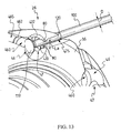
- the hub body illustrated in the attached figures is intended to integrally house inside of it a longitudinal shaft 10a (see figure 16) which in turn is intended to be associated, at the opposite free ends thereof, with a bicycle frame (not illustrated).
- a hub is intended to be associated with a rim 10c of a bicycle wheel through a plurality of spokes 100 (see figure 17).
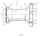
- the hub body 10 illustrated in the aforementioned figure comprises a substantially tubular body 20 extending along a longitudinal axis X-X and provided with a pair of flanged opposite end portions 25, 26 having respective annular front surfaces 35, 36 on which a plurality of seats are formed, all respectively indicated with 45 in the left-hand end portion 25 and with 46, 47 in the right-hand end portion 26 (with reference to the orientation of the hub body 10 of figure 1).
- the aforementioned seats 45, 46, 47 are each adapted to house an end portion of a respective spoke 100, illustrated in figures 3, 5, 10, 13-15 and 17.
- the hub body 10 illustrated in the attached figures 1 and 5 is adapted to be used in a hub for a rear wheel of a bicycle (illustrated in figures 16 and 17) or for a front wheel with disc brakes.
- the seats 45 formed in the annular front surface 35 of the end portion 25 are orientated in such a way to allow a connection of the spokes 100 according to a conventional radial configuration (better illustrated in figures from 2 to 5), whereas the seats 46, 47 formed in the annular front surface 36 of the end portion 26 are orientated in such a way to allow an arrangement of the spokes according to a conventional crossed configuration (better illustrated in figure 12).
- the end portion 26, in the specific case illustrated in the attached drawings, is intended to receive a conventional body 10b carrying the sprockets (illustrated in figure 16 and 17), used in the assembly onto the hub of the rear wheel of a bicycle of a group of sprockets of a bicycle gearshift, or the brake disc of a front wheel.
- a hub body for a bicycle wheel with spokes that are radial on one side and crossed on the other like the one illustrated in the attached figures.
- a man skilled in the art will recognise that what has been stated is also applicable to a hub body for different wheels, like a hub body having a pair of end portions 25 and 26 of the same type (preferably both configured in such a way to allow a connection of the spokes according to a radial or crossed configuration).
- the seats formed in the annular front surface of the end portion of the hub can be orientated in such a way to allow a connection of the spokes according to a non-radial and non-crossed configuration.
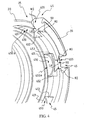
- each seat 45 formed on the front annular surface 35 of the end portion 25 of the tubular body 20 comprises a first housing portion 450 for a head 110 of attachment to the hub of a respective spoke 100 and a second housing portion 455 for a body portion 120 of said spoke 100 immediately adjacent to the head 110 of attachment to the hub.
- the first housing portion 450 for the head 110 of attachment to the hub of the spoke 100 has a shape matching that of the head 110 of attachment to the hub of the spoke 100 and comprises a base opening 450a, a flat front surface 451 adapted to cooperate in abutment with the head 110 of attachment to the hub of the spoke 100 when said head 110 of attachment to the hub is housed in the first housing portion 450 of the seat 45, and a pair of cylindrical side surface portions 452, 453 having a shape matching the side surface portions 111, 112 of the head 110 of the spoke 100.
- each seat 45 also comprises a pair of spoke retention elements 80 adapted in particular to prevent the spokes 100 from moving along a direction parallel to the aforementioned longitudinal axis X-X of the hub body 10 towards the outside of the hub body 10 itself.
- the spoke retention elements 80 are an integral part of the annular front surface 35 of the hub body 10 and extend circumferentially only partially on the aforementioned seats 45 so as to be cantilevered.
- each pair of elements 80 extends on each first housing portion 450 of the seats 45 on opposite sides so as to define such a first housing portion 450 at the top and so as to delimit an opening 90 of predetermined circumferential length L a between them.
- the opening 90 allows easy assembly onto the hub body of the present invention of flat spokes like those illustrated in the attached drawings 3, 5 and 10, as shall be explained in the following of the present description.
- Figure 2 shows the hub body 10 in a configuration without spokes mounted thereon
- figure 3 shows the hub body 10 in a configuration in which all of the spokes are shown correctly mounted thereon (i.e. with the respective heads 110 of attachment to the hub housed in the appropriate first housing portions 450 of the seats 45) apart from one, indicated with 100a, which is shown in an incomplete assembly configuration and/or untightened.
- the reference numerals being identical for all of the seats and for all of the spokes illustrated, are shown at just some of the seats and at just some of the spokes.
- FIGS. 6 and 7 show alternative embodiments of the hub body of the present invention.
- the hub body illustrated in these figures differs from the one described above with reference to figures from 1 to 5 for the sole fact that each pair of elements 80, instead of extending at the first housing portion 450 of the seats 45, extends, respectively, on a radially outer zone of the front surface 35 of the hub body 10 (figure 6) and on an intermediate zone of the front surface 35 of the hub body 10 at the second housing portion 455 of the seats 45 (figure 7).
- the hub body illustrated in figure 6 and 7 is totally identical to the hub body 10 illustrated in figures from 1 to 5 and, therefore, their structural characteristics shall not be repeated here.
- the reference numerals being identical for all of the seats, are shown at just one seat.
- FIG 8 shows a further alternative embodiment of the hub body of the present invention.
- the hub body illustrated in this figure differs from the one described above with reference to figure 6 for the sole fact that each seat 45 comprises, instead of a pair of elements 80 separated by an opening 90, a single element 80a that extends cantilevered on the seat 45 from one side thereof for part of the circumferential length of the seat itself so as to define the opening 90 of predetermined length L a between such an element 80a and the opposite side of the seat 45.
- the hub body illustrated in figure 8 is totally identical to the hub body 10 illustrated in figures from 1 to 5 and, therefore, their structural characteristics shall not be repeated here. Also in this case, for the sake of simplicity of illustration and of reading of the figures, the reference numerals, being identical for all of the seats, are shown at just one seat.
- FIGS 9 and 10 show a further alternative embodiment of the hub body of the present invention, respectively in a configuration without spokes and in a configuration with spokes mounted thereon.
- the hub body illustrated in these figures differs from the one described above with reference to figures from 1 to 5 for the sole fact that each seat 45 comprises, instead of a pair of elements 80 separated by and opening 90, a single element 81 that extends like a bridge on the seat 45 for the entire circumferential length of the seat itself without solution of continuity with the annular front surface 35 of the hub body 10.
- the hub body illustrated in figure 9 and 10 is totally identical to the hub body 10 illustrated in figures from 1 to 5 and, therefore, their structural characteristics shall not be repeated here.
- the reference numerals being identical for all of the seats, are shown at just one seat.
- FIG 11 shows a further alternative embodiment of the hub body of the present invention.
- the hub body illustrated in these figures differs from the one described above with reference to figures 9 and 10 for the sole fact that the seat 45 comprises a single element 82 that extends like a bridge radially towards the inside of the hub body 10 and circumferentially on the seat 45 for a portion of length at least equal to (preferably greater than) the circumferential length of the seat itself without solution of continuity with the annular front surface 35 of the hub body 10.
- the hub body illustrated in figure 11 is totally identical to the hub body 10 illustrated in figures from 1 to 5 and, therefore, their structural characteristics shall not be repeated here.
- the reference numerals being identical for all of the seats, are shown at just one seat.
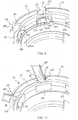
- figure 12 illustrates the end portion 26 opposite to the end portion 25 described above and adapted to the connection of spokes according to a conventional crossed configuration.
- the seats 46 and 47 comprise, respectively, a first housing portion 460, 470 for the heads 110 of attachment to the hub of the spokes 100 and a second housing portion 465, 475 for the spoke body portion 120 immediately adjacent to the head 110 of attachment to the hub.
- the arrangement and/or orientation of the seats 46 and 47 on the annular front surface 36 of the end portion 26 is totally conventional, as shown for example in the quoted patent US 6,036,279, and therefore it shall not be described in this context.
- the seats 46 are defined on a first annular portion 261 of the end portion 26 and are of the conventional type (i.e. without retention elements 80, 80a, 81 or 82), whereas the seats 47 are defined on a second annular portion 262 contiguous to the annular portion 261 and outside of it along the longitudinal axis X-X and are provided with retention elements 80 in accordance with the present invention.
- the spokes are mounted in the appropriate seats 46 and 47, the spokes mounted in the seats 47 are prevented from any possibility of movement along the longitudinal axis of the spoke itself and in turn such spokes prevent any movement of the respective spokes that they cross over and that are mounted in the seats 46.
- the seats 47 are totally identical to the seats 45 provided on the opposite front surface 25 (apart from their different orientation on the annular front surface 35) and therefore they shall not be described in detail in the rest of the present description.
- each first housing portion 470 of the seats 47 partially overlaps a respective first housing portion 460 of the seats 46; in such a way, when the spokes are mounted in the appropriate seats 46 and 47, the spokes mounted in the seats 47 have the respective heads 110 of attachment to the hub overlapping the heads 110 of attachment to the hub of the spokes mounted in the seats 46.
- Figure 13 shows a further alternative embodiment of the hub body of the present invention.
- the seats 46 and 47 comprise, respectively, a first housing portion 460, 470 for the heads 110 of attachment to the hub of the spokes 100 and a second housing portion 465, 475 for the spoke body portion 120 immediately adjacent to the head 110 of attachment to the hub.
- the first housing portions 460, 470 of the head 110 of attachment to the hub of the respective spoke 100 comprise respective side surfaces 462, 472 having a shape matching that of the head 110 of attachment to the hub of the respective spokes 100.
- the arrangement and/or orientation of the seats 46 and 47 on the annular front surface 36 of the end portion 26 is totally conventional and therefore it shall not be described in this context.
- the seats 46 are of the conventional type (i.e. without retention elements 80, 80a, 81 or 82), whereas the seats 47 are provided with retention means in accordance with the present invention.
- the retention means comprise a pair of opposite retention elements 80 that define between them an opening of length L a shorter than the diameter D of the spoke body 100.
- Figures 14 and 15 show alternative embodiments of the hub body of the present invention. Such embodiments differ from the one illustrated in figure 13 in that the retention means comprise a single element 81 that extends like a bridge on the seat 47 without solution of continuity with the annular front surface 36 of the hub body 10.
- the element 81 is defined at the first housing portion 470 for the head 110 of attachment to the hub of the spoke 100, whereas in the specific example illustrated in figure 15, the element 81 is defined at the second housing portion 475 for the spoke body portion 120 immediately adjacent to the head 110 of attachment to the hub.
- the retention of the spokes mounted in the seats 47 is achieved through abutment of such spokes against the retention elements 80 properly provided in the seats 47, whereas the retention of the spokes mounted in the seats 46 is achieved through abutment of such spokes against the spokes mounted in the seats 47.
- the use of such a hub body allows easy assembly of flat spokes, like for example the spoke 100 illustrated in figure 5, having a width L R greater, and a thickness S R smaller, than the circumferential length L a of the opening 90.
- the assembly of such a spoke in the respective seat 45 is carried out by simply positioning the spoke with its thickness S R in front of the opening 90, then moving the spoke through the opening 90 until it is introduced in the respective seat 45, and finally rotating the spoke about its own longitudinal axis by 90° so as to position it with its portion of width L R arranged substantially parallel to the annular front surface 35 of the hub body 10.
- the spoke 100 is then moved radially towards the outside of the hub body 10 (i.e. towards the rim) until the head 110 of attachment to the hub is completely housed in the first housing portion 450 of the seat 45.
- any type of spoke having a cross section defined by two different dimensions and in particular with spokes having a longitudinally flat body portion 120 (for example spokes with a rectangular or elliptical section) having, in cross section, a minimum size (for example the thickness S R of the spoke) that is smaller than the circumferential length L a of the opening 90 and a maximum size (for example the width L R of the spoke) that is greater than the aforementioned circumferential length L a of the opening 90.
- a minimum size for example the thickness S R of the spoke
- a maximum size for example the width L R of the spoke
- the spoke in the assembly operations of the spoke on the hub body the spoke is firstly inserted with its end of attachment to the rim at the centre of the end portion 25 of the hub body 10 through the base opening 450a defined in the first housing portion 450 between the front surface 451 and the retention element 81 forming a bridge provided in the seat 45.
- the spoke is then moved radially towards the outside of the hub body (i.e. towards the rim) until the head 110 of attachment to the hub is housed in the first housing portion 450 of the seat 45.
- the spoke is entirely cylindrical, the assembly operations are similar to those described above with reference to figures 9 and 10 (irrespective of whether the retention means consist of a pair of elements 80 or a single bridge element 81, 82).
- the spoke is firstly inserted with its end of attachment to the rim at the centre of the end portion 25 of the hub body 10 through the base opening 450a defined in the first housing portion 450 of the seat 45 by moving it radially towards the outside of the hub body (i.e. towards the rim) until the head 110 of attachment to the hub is housed in the first housing portion 450 of the seat 45.
- the spoke is provided with at least one flat zone with thickness S and width L R and the seats comprise a pair of retention elements 80 with opening 90 of circumferential length L a that is greater than the thickness S of the flat zone of the spoke and smaller than the width L R of the spoke
- the assembly operations are totally analogous to those described above with reference to the flat spokes.
- the spoke is positioned with the thickness S of its flat zone in front of the opening 90. Then the spoke is moved through the opening 90 until it is introduced into the respective seat 45, and finally the spoke is rotated about its longitudinal axis by 90° so as to position it with its portion of width L R arranged substantially parallel to the annular front surface 35 of the hub body 10. The spoke is then moved radially towards the outside of the hub body 10 (i.e. towards the rim) until the head 110 of attachment to the hub is completely housed in the first housing portion 450 of the seat 45.
Landscapes
- Engineering & Computer Science (AREA)
- Mechanical Engineering (AREA)
- Axle Suspensions And Sidecars For Cycles (AREA)
- Connection Of Plates (AREA)
- Tires In General (AREA)
- Braking Arrangements (AREA)
- Rolling Contact Bearings (AREA)
Abstract
Description
- The present invention relates to a hub body for a bicycle wheel, in particular, for a racing bicycle wheel. The invention also relates to a hub for a bicycle wheel comprising such a hub body and to a bicycle wheel comprising such a hub.
- As known, a bicycle wheel comprises a plurality of spokes extending between the hub, which constitutes the central element of the wheel intended to be associated with the bicycle frame, and the rim on which the tire is mounted.
- The hub, in turn, comprises a body on which the spokes and a shaft are intended to be mounted and a shaft, integrally and rotatably associated through bearings with said body and extending longitudinally inside of it, intended to be connected through its free ends to the bicycle frame.
- An example of a hub known in the art and particularly advantageous in terms of practicality and simplicity of assembly of the spokes is described in US 6,036,279 of the same Applicant. This is, in particular, a hub for flat spokes, in which the hub body comprises a tubular end portion terminating with an annular front surface having a plurality of radial front recesses constituting spoke housing seats. Each spoke has a widened head of attachment to the hub having a T-shaped configuration. Each spoke also has a flattened spoke body portion immediately adjacent to the widened head. The widened head of attachment to the hub is housed inside the tubular end portion of the hub body, whereas the flat portion of the body of the spoke is housed in the recess formed on the front annular surface of the hub body. The T-shape of the widened head of attachment to the hub prevents the spoke from moving in the radial direction of the wheel towards the rim once the spoke has been tightened. The movements of the spoke in the axial direction of the hub, towards the outside thereof, on the other hand, are prevented by an annular edge formed at the free end of the hub and bent radially inwards; such an edge extends circumferentially between each pair of contiguous recesses and defines an abutment surface for an upper portion of the front surface of the widened head of attachment to the hub of each spoke. Such an edge also defines on the recess an opening of a size equal to the width of the flat spoke body portion.
- The Applicant has found that a hub of the type described above has the drawback that, following untightening or breaking of a spoke that causes a movement of the spoke in the radial direction of the wheel towards the centre of the hub (that is a movement of the spoke along its longitudinal axis towards the centre of the hub), the spoke can come out from the front recess in which it is housed and thus move away from the hub, thus compromising the correct operation of the wheel and/or constituting a danger to the cyclists, especially during a race where cyclists ride in groups.
- The Applicant has thus conceived and manufactured a hub for a bicycle wheel that does not have the drawback discussed above.
- The present invention therefore relates, in a first aspect thereof, to a hub body for a bicycle wheel, comprising:
- a substantially tubular body extending along a longitudinal axis X-X and provided with a pair of opposite end portions, wherein at least one end portion of said pair of opposite end portions comprises an annular front surface;
- a plurality of seats formed on said annular front surface of said body and adapted to house an end portion of respective spokes;
- Throughout the present description and in the subsequent claims, the expression: "hub body", is used to indicate the body on which the spokes of the bicycle wheel are intended to be mounted. The term: "hub", on the other hand, is used to indicate, in the case of a front hub, the group intended to be associated with the bicycle frame and, in the case of a rear hub, the group comprising the hub body, the longitudinal shaft provided inside the hub body and the body carrying the sprockets.
- Advantageously, in the hub body of the present invention the drawback discussed above with reference to the hub of the prior art is overcome by providing the seats formed on the annular front surface of the hub body with suitable retention means adapted to prevent the spokes from moving in the longitudinal direction of the hub body. The spokes, therefore, are held in the respective seats in whatever operating condition of the wheel, even in the case of untightening or breaking that causes a radial movement of the spoke itself towards the centre of the wheel.
- Advantageously, the hub body of the present invention is adapted to the manufacturing of bicycle wheels according to the conventional radial configurations (that is with the spokes of the wheel all orientated radially) and crossed configuration (that is with each spoke at a side of the hub that crosses at least one other spoke at the same side of the hub). Preferably, in the case of a radial configuration, all of the seats of said plurality of seats comprise the aforementioned retention means. On the other hand, in the case of a crossed wheel configuration, only some seats of said plurality of seats comprise the aforementioned retention means, as shall be explained more clearly in the rest of the present description.
- Even more advantageously, the hub body of the present invention can be used to manufacture a hub for both rear wheels and front wheels. Preferably, in the case of a hub for a rear wheel or for a front wheel with disc brake, the opposite end portions of the hub body of the present invention are different and adapted to realise a radial configuration and a crossed configuration, respectively, whereas in the case of a hub for a front wheel without disc brake, the opposite end portions of the hub body of the present invention are preferably identical and, more preferably, are both adapted to realise a radial configuration.
- However, the man skilled in the art will understand that the hub body of the present invention allows to realise further and/or less preferred configurations with respect to those described above, such as rear wheel configurations in which the opposite end portions of the hub body of the present invention are identical (for example both crossed), front wheel configurations in which the opposite end portions of the hub body of the present invention are identical and both adapted to realise a crossed configuration, or generic wheel configurations in which the spokes are arranged not radially.
- Preferably, the retention means are integrally formed with the annular front surface of the hub body of the present invention and extend at least partially on the aforementioned seats. Advantageously, the retention of the spokes in the respective seats is thus achieved without needing to use additional elements to (and/or distinct from) the hub body itself. This contributes to the constructive simplification and to the containment of production cost, weight and encumbrance of the hub, thus satisfying the ongoing requirements of manufacturers of bicycles and/or components for racing bicycles.
- In accordance with a first preferred embodiment of the present invention, the aforementioned retention means define an opening of predetermined length and smaller than a maximum dimension of a cross section of a spoke body portion intended to be associated with said substantially tubular body. Advantageously, the provision of such an opening allows easy assembly onto the hub body of the present invention of spokes having a longitudinally flat body portion (for example spokes with a rectangular or elliptical section) and in particular having, in cross section, a minimal size (for example the thickness of the spoke) smaller than the circumferential length of such an opening and a maximum size (for example the width of the spoke) greater than the circumferential length of the opening, as shall be explained more clearly in the rest of the present description.
- Preferably, said opening of predetermined length is defined by at least one element that extends cantilevered on a respective seat of said plurality of seats.
- In a first embodiment of the hub body of the present invention, the aforementioned opening of predetermined length is defined by a single element that extends cantilevered on the respective seat from a side of the seat itself. In a preferred embodiment, the aforementioned opening is defined between a pair of elements that extend from opposite sides on the respective seat of said plurality of seats. More preferably, in the case of a wheel with radial configuration, the aforementioned single element or the elements of the aforementioned pair of elements extend on the respective seat along a circumferential direction.
- Preferably, in the case of flat spokes, the predetermined length of the aforementioned opening is greater than a minimum size of a cross section of a flat spoke body portion intended to be associated with the aforementioned substantially tubular body and smaller than a maximum size of the aforementioned cross section of said flat spoke body portion. On the other hand, in the case of cylindrical spokes, the predetermined length of the aforementioned opening is smaller than the diameter of a cross section of a portion of the cylindrical spoke body.
- In accordance with an alternative embodiment of the hub body of the present invention, the retention means comprise a single bridge-type element that extends (in the specific case of a wheel with radial configuration, along a circumferential direction) on a respective seat of said plurality of seats without solution of continuity with the front annular surface of said substantially tubular body. In such a case, the assembly of the spokes on the hub body is carried out, irrespective of the type of spokes used, according to methods different to those of the aforementioned first preferred embodiment, as shall be explained more clearly in the rest of the present description.
- Preferably, the aforementioned seats comprise a first housing portion for a head of attachment to the hub of a respective spoke and a second housing portion for a body portion of said spoke immediately adjacent to the head of attachment to the hub, and the retention means are defined at the aforementioned first housing portion. In respective alternative embodiments, the retention means can, however, be defined at the aforementioned second housing portion or at a zone interposed between the aforementioned first housing portion and the aforementioned second housing portion.
- In further alternative embodiments of the hub body of the present invention, the retention means extend radially and towards the inside of the aforementioned substantially tubular body or radially and towards the outside of the aforementioned body.
- In the preferred embodiment of the hub body of the present invention, the housing portion for the head of attachment to the hub of the spoke has a shape (preferably frusto-conical) matching that of said head of attachment to the hub of the spoke.
- As already stated, the aforementioned seats can be orientated on the front annular surface of the hub body of the present invention so as to realise a configuration of spokes arranged radially, a configuration of spokes arranged not radially or a configuration with crossed spokes. In this last case, preferably, the hub body of the present invention comprises:
- a plurality of first seats defined on a first annular portion of a first end portion of said substantially tubular body and adapted to house an end portion of respective first spokes;
- a plurality of second seats defined on a second annular portion of said first end portion of said substantially tubular body and adapted to house an end portion of respective second spokes;
- In such a case, the retention of the aforementioned second spokes in the seats of the aforementioned plurality of second seats is achieved through abutment of such spokes against the retention means properly provided in the seats of the aforementioned plurality of second seats, whereas the retention of the aforementioned first spokes in the seats of the aforementioned plurality of first seats is achieved through abutment of such spokes against the aforementioned second spokes, as shall be explained more clearly in the rest of the present description.
- Preferably, both of the end portions of said pair of opposite end portions comprise an annular front surface.
- In a second aspect thereof, the present invention relates to a hub for a bicycle wheel, comprising:
- a hub body comprising a plurality of seats adapted to house an end portion of respective spokes;
- a shaft extending along a longitudinal axis X-X inside said hub body and adapted to be associated with a bicycle frame;
- Such a hub thus has all of the advantageous characteristics discussed above with reference to the hub body of the present invention.
- In a third aspect thereof, the present invention relates to a bicycle wheel, comprising:
- a hub;
- a rim;
- a plurality of spokes extending between said hub and said rim;
- Such a wheel thus has all of the advantageous characteristics discussed above with reference to the hub body of the present invention.
- Further characteristics and advantages of the present invention shall become clearer from the following detailed description of some preferred embodiments thereof, made with reference to the attached drawings. In such drawings,
- figure 1 is a schematic side view of a first embodiment of a hub body in accordance with the present invention;
- figure 2 is a schematic front view of the left-hand end portion of the hub body of figure 1;
- figure 3 is a schematic front view of the left-hand end portion of the hub body of figure 1 in a configuration with all of the spokes mounted (apart from one, which is illustrated in the assembly and/or tightening step);
- figure 4 is a schematic perspective and enlarged view of a detail of the left-hand end portion of the hub body of figure 1;
- figure 5 is a schematic perspective and enlarged view of the detail of figure 4 in a configuration with spokes mounted thereon;
- figure 6 is a schematic perspective and enlarged view of a detail of an end portion of a second alternative embodiment of the hub body of the present invention;
- figure 7 is a schematic perspective and enlarged view of a detail of an end portion of a third alternative embodiment of the hub body of the present invention;
- figure 8 is a schematic perspective and enlarged view of a detail of an end portion of a fourth alternative embodiment of the hub body of the present invention;
- figure 9 is a schematic perspective and enlarged view of a detail of an end portion of a fifth embodiment of the hub body of the present invention;
- figure 10 is a schematic perspective and enlarged view of the detail of figure 9 in a configuration with spokes mounted thereon;
- figure 11 is a schematic perspective and enlarged view of a detail of an end portion of a sixth embodiment of the hub body of the present invention;
- figure 12 is a schematic perspective view of the right-hand end portion of the hub body of figure 1;
- figure 13 is a schematic perspective and enlarged view of a detail of an end portion of a seventh embodiment of the hub body of the present invention, in a configuration with one spoke mounted thereon;
- figure 14 is a schematic perspective and enlarged view of a detail of an end portion of an eighth embodiment of the hub body of the present invention, in a configuration with one spoke mounted thereon;
- figure 15 is a schematic perspective and enlarged view of a detail of an end portion of a ninth embodiment of the hub body of the present invention;
- figure 16 is a schematic front view of a hub comprising the hub body of figure 1;
- figure 17 is a schematic perspective view of a wheel comprising the hub of figure 16.
- In the attached figures from 1 to 5 and 12, and in particular in figures 1, 5 and 12, a hub body in accordance with a first exemplificative embodiment of the present invention is indicated with 10, whereas figures from 6 to 9 and from 13 to 15 show respective alternative embodiments of the hub body of the present invention.
- The hub body illustrated in the attached figures is intended to integrally house inside of it a longitudinal shaft 10a (see figure 16) which in turn is intended to be associated, at the opposite free ends thereof, with a bicycle frame (not illustrated). Such a hub is intended to be associated with a rim 10c of a bicycle wheel through a plurality of spokes 100 (see figure 17).
- The
hub body 10 illustrated in the aforementioned figure comprises a substantiallytubular body 20 extending along a longitudinal axis X-X and provided with a pair of flangedopposite end portions hand end portion 25 and with 46, 47 in the right-hand end portion 26 (with reference to the orientation of thehub body 10 of figure 1). Theaforementioned seats respective spoke 100, illustrated in figures 3, 5, 10, 13-15 and 17. - The
hub body 10 illustrated in the attached figures 1 and 5 is adapted to be used in a hub for a rear wheel of a bicycle (illustrated in figures 16 and 17) or for a front wheel with disc brakes. In thehub body 10, theseats 45 formed in the annularfront surface 35 of theend portion 25 are orientated in such a way to allow a connection of thespokes 100 according to a conventional radial configuration (better illustrated in figures from 2 to 5), whereas theseats front surface 36 of theend portion 26 are orientated in such a way to allow an arrangement of the spokes according to a conventional crossed configuration (better illustrated in figure 12). Theend portion 26, in the specific case illustrated in the attached drawings, is intended to receive aconventional body 10b carrying the sprockets (illustrated in figure 16 and 17), used in the assembly onto the hub of the rear wheel of a bicycle of a group of sprockets of a bicycle gearshift, or the brake disc of a front wheel. - Throughout the present description explicit reference shall be made to a hub body for a bicycle wheel with spokes that are radial on one side and crossed on the other, like the one illustrated in the attached figures. However, a man skilled in the art will recognise that what has been stated is also applicable to a hub body for different wheels, like a hub body having a pair of
end portions - In other non-illustrated embodiments of the hub body of the present invention, the seats formed in the annular front surface of the end portion of the hub can be orientated in such a way to allow a connection of the spokes according to a non-radial and non-crossed configuration.
- As better illustrated in figures from 2 to 5, each
seat 45 formed on the frontannular surface 35 of theend portion 25 of thetubular body 20 comprises afirst housing portion 450 for ahead 110 of attachment to the hub of arespective spoke 100 and asecond housing portion 455 for abody portion 120 of said spoke 100 immediately adjacent to thehead 110 of attachment to the hub. More specifically, thefirst housing portion 450 for thehead 110 of attachment to the hub of thespoke 100 has a shape matching that of thehead 110 of attachment to the hub of thespoke 100 and comprises abase opening 450a, a flatfront surface 451 adapted to cooperate in abutment with thehead 110 of attachment to the hub of thespoke 100 when saidhead 110 of attachment to the hub is housed in thefirst housing portion 450 of theseat 45, and a pair of cylindricalside surface portions side surface portions head 110 of thespoke 100. When thespoke 100 is mounted on the hub and is suitably tightened these side surface portions go into abutment against the side surfaces 452, 453 of thefirst housing portion 450 of theseat 45, thus preventing thespoke 100 from any possibility of movement along the longitudinal axis of the spoke itself. - In accordance with the present invention and with particular reference to the exemplificative embodiment of the
hub body 10 of the present invention illustrated in figures from 2 to 5, eachseat 45 also comprises a pair ofspoke retention elements 80 adapted in particular to prevent thespokes 100 from moving along a direction parallel to the aforementioned longitudinal axis X-X of thehub body 10 towards the outside of thehub body 10 itself. - In the specific example illustrated in the attached drawings, the
spoke retention elements 80 are an integral part of the annularfront surface 35 of thehub body 10 and extend circumferentially only partially on theaforementioned seats 45 so as to be cantilevered. In particular, each pair ofelements 80 extends on eachfirst housing portion 450 of theseats 45 on opposite sides so as to define such afirst housing portion 450 at the top and so as to delimit anopening 90 of predetermined circumferential length La between them. Theopening 90 allows easy assembly onto the hub body of the present invention of flat spokes like those illustrated in the attacheddrawings - Figure 2 shows the
hub body 10 in a configuration without spokes mounted thereon, whereas figure 3 shows thehub body 10 in a configuration in which all of the spokes are shown correctly mounted thereon (i.e. with therespective heads 110 of attachment to the hub housed in the appropriatefirst housing portions 450 of the seats 45) apart from one, indicated with 100a, which is shown in an incomplete assembly configuration and/or untightened. For the sake of simplicity of illustration and of reading of the figure, the reference numerals, being identical for all of the seats and for all of the spokes illustrated, are shown at just some of the seats and at just some of the spokes. - Figures 6 and 7 show alternative embodiments of the hub body of the present invention. The hub body illustrated in these figures differs from the one described above with reference to figures from 1 to 5 for the sole fact that each pair of
elements 80, instead of extending at thefirst housing portion 450 of theseats 45, extends, respectively, on a radially outer zone of thefront surface 35 of the hub body 10 (figure 6) and on an intermediate zone of thefront surface 35 of thehub body 10 at thesecond housing portion 455 of the seats 45 (figure 7). For the rest, the hub body illustrated in figure 6 and 7 is totally identical to thehub body 10 illustrated in figures from 1 to 5 and, therefore, their structural characteristics shall not be repeated here. Also in this case, for the sake of simplicity of illustration and of reading of the figures, the reference numerals, being identical for all of the seats, are shown at just one seat. - Figure 8 shows a further alternative embodiment of the hub body of the present invention. The hub body illustrated in this figure differs from the one described above with reference to figure 6 for the sole fact that each
seat 45 comprises, instead of a pair ofelements 80 separated by anopening 90, a single element 80a that extends cantilevered on theseat 45 from one side thereof for part of the circumferential length of the seat itself so as to define theopening 90 of predetermined length La between such an element 80a and the opposite side of theseat 45. For the rest, the hub body illustrated in figure 8 is totally identical to thehub body 10 illustrated in figures from 1 to 5 and, therefore, their structural characteristics shall not be repeated here. Also in this case, for the sake of simplicity of illustration and of reading of the figures, the reference numerals, being identical for all of the seats, are shown at just one seat. - Figures 9 and 10 show a further alternative embodiment of the hub body of the present invention, respectively in a configuration without spokes and in a configuration with spokes mounted thereon. The hub body illustrated in these figures differs from the one described above with reference to figures from 1 to 5 for the sole fact that each
seat 45 comprises, instead of a pair ofelements 80 separated by andopening 90, asingle element 81 that extends like a bridge on theseat 45 for the entire circumferential length of the seat itself without solution of continuity with the annularfront surface 35 of thehub body 10. For the rest, the hub body illustrated in figure 9 and 10 is totally identical to thehub body 10 illustrated in figures from 1 to 5 and, therefore, their structural characteristics shall not be repeated here. Also in this case, for the sake of simplicity of illustration and of reading of the figures, the reference numerals, being identical for all of the seats, are shown at just one seat. - Figure 11 shows a further alternative embodiment of the hub body of the present invention. The hub body illustrated in these figures differs from the one described above with reference to figures 9 and 10 for the sole fact that the
seat 45 comprises asingle element 82 that extends like a bridge radially towards the inside of thehub body 10 and circumferentially on theseat 45 for a portion of length at least equal to (preferably greater than) the circumferential length of the seat itself without solution of continuity with the annularfront surface 35 of thehub body 10. For the rest, the hub body illustrated in figure 11 is totally identical to thehub body 10 illustrated in figures from 1 to 5 and, therefore, their structural characteristics shall not be repeated here. Also in this case, for the sake of simplicity of illustration and of reading of the figure, the reference numerals, being identical for all of the seats, are shown at just one seat. - As already stated, figure 12 illustrates the
end portion 26 opposite to theend portion 25 described above and adapted to the connection of spokes according to a conventional crossed configuration. Also in this case, theseats first housing portion heads 110 of attachment to the hub of thespokes 100 and asecond housing portion spoke body portion 120 immediately adjacent to thehead 110 of attachment to the hub. The arrangement and/or orientation of theseats front surface 36 of theend portion 26 is totally conventional, as shown for example in the quoted patent US 6,036,279, and therefore it shall not be described in this context. - Also in this case, for the sake of simplicity of illustration and of reading of the figure, the reference numerals, being identical for all of the seats, are shown at just some of the seat themselves.
- As shown in figure 12, the
seats 46 are defined on a firstannular portion 261 of theend portion 26 and are of the conventional type (i.e. withoutretention elements seats 47 are defined on a secondannular portion 262 contiguous to theannular portion 261 and outside of it along the longitudinal axis X-X and are provided withretention elements 80 in accordance with the present invention. In such a way, when the spokes are mounted in theappropriate seats seats 47 are prevented from any possibility of movement along the longitudinal axis of the spoke itself and in turn such spokes prevent any movement of the respective spokes that they cross over and that are mounted in theseats 46. - The
seats 47 are totally identical to theseats 45 provided on the opposite front surface 25 (apart from their different orientation on the annular front surface 35) and therefore they shall not be described in detail in the rest of the present description. The same for theseats 46, which differ from theseats 47 for the sole fact that they do not haveretention elements - In a possible variant not illustrated, each
first housing portion 470 of theseats 47 partially overlaps a respectivefirst housing portion 460 of theseats 46; in such a way, when the spokes are mounted in theappropriate seats seats 47 have therespective heads 110 of attachment to the hub overlapping theheads 110 of attachment to the hub of the spokes mounted in theseats 46. - Figure 13 shows a further alternative embodiment of the hub body of the present invention. In particular, such a figure illustrates an
end portion 26 adapted to the connection of cylindrical spokes, in particular cylindrical spokes with frusto-conical head, according to a conventional crossed configuration. Also in this case, theseats first housing portion heads 110 of attachment to the hub of thespokes 100 and asecond housing portion spoke body portion 120 immediately adjacent to thehead 110 of attachment to the hub. Thefirst housing portions head 110 of attachment to the hub of the respective spoke 100 comprise respective side surfaces 462, 472 having a shape matching that of thehead 110 of attachment to the hub of therespective spokes 100. The arrangement and/or orientation of theseats front surface 36 of theend portion 26 is totally conventional and therefore it shall not be described in this context. - As shown in figure 13, the
seats 46 are of the conventional type (i.e. withoutretention elements seats 47 are provided with retention means in accordance with the present invention. In particular, the retention means comprise a pair ofopposite retention elements 80 that define between them an opening of length La shorter than the diameter D of thespoke body 100. In such a way, when the spokes are mounted in theappropriate seats seats 47 are prevented from any possibility of movement along the longitudinal axis of the spoke itself and in turn such spokes prevent any movement of the respective spokes that they cross over and that are mounted in theseats 46. - Figures 14 and 15 show alternative embodiments of the hub body of the present invention. Such embodiments differ from the one illustrated in figure 13 in that the retention means comprise a
single element 81 that extends like a bridge on theseat 47 without solution of continuity with the annularfront surface 36 of thehub body 10. In the specific example illustrated in figure 14, theelement 81 is defined at thefirst housing portion 470 for thehead 110 of attachment to the hub of thespoke 100, whereas in the specific example illustrated in figure 15, theelement 81 is defined at thesecond housing portion 475 for thespoke body portion 120 immediately adjacent to thehead 110 of attachment to the hub. - In the embodiment of the
hub body 10 illustrated in figures from 1 to 5 and in the variants illustrated in figures from 6 to 10 and 13, in the case of breaking or untightening of the spokes, a possible movement of thespoke 100 away from theseat 45 is prevented by the counter action carried out on the side surface of the spoke itself by the pair ofretention elements 80, as shown with reference to the spoke 100a in figure 3 (obviously, when the width LR is greater than the length La of the opening 90). - It is clear that such a retention effect can be obtained both for flat spokes and spokes having a
portion 120, immediately adjacent to thehead 110 of attachment to the hub, of the cylindrical type with diameter D greater than the length La of theopening 90. - In the same way, in the embodiments of the
hub body 10 illustrated in figures 9-11, in the case of breaking or untightening of the spokes, a possible movement of thespoke 100 away from theseat 45 is prevented by the counter action carried out on the side surface of the spoke itself by thebridge element - On the other hand, with reference to the crossed configuration of the variants illustrated in figures 12 and 13, the retention of the spokes mounted in the
seats 47 is achieved through abutment of such spokes against theretention elements 80 properly provided in theseats 47, whereas the retention of the spokes mounted in theseats 46 is achieved through abutment of such spokes against the spokes mounted in theseats 47. - In the same way, in the embodiments of the
hub body 10 illustrated in figures 14 and 15, in the case of breaking or untightening of the spokes, a possible movement of thespoke 100 away from theseat 47 is prevented by the counter action carried out by thebridge element 81 on the side surface of the spoke itself. - Hereafter it shall be described the assembly operation of the spokes in the respective seats of the different embodiments of the hub body described above. For the sake of simplicity, reference shall be made to a radial configuration, like the one illustrated in figures 2-11.
- With reference to the embodiments of the
hub body 10 illustrated in figures from 1 to 8, it has already been stated that the use of such a hub body allows easy assembly of flat spokes, like for example thespoke 100 illustrated in figure 5, having a width LR greater, and a thickness SR smaller, than the circumferential length La of theopening 90. The assembly of such a spoke in therespective seat 45 is carried out by simply positioning the spoke with its thickness SR in front of theopening 90, then moving the spoke through theopening 90 until it is introduced in therespective seat 45, and finally rotating the spoke about its own longitudinal axis by 90° so as to position it with its portion of width LR arranged substantially parallel to the annularfront surface 35 of thehub body 10. Thespoke 100 is then moved radially towards the outside of the hub body 10 (i.e. towards the rim) until thehead 110 of attachment to the hub is completely housed in thefirst housing portion 450 of theseat 45. - It is clear that the same assembly methods can be obtained with any type of spoke having a cross section defined by two different dimensions, and in particular with spokes having a longitudinally flat body portion 120 (for example spokes with a rectangular or elliptical section) having, in cross section, a minimum size (for example the thickness SR of the spoke) that is smaller than the circumferential length La of the
opening 90 and a maximum size (for example the width LR of the spoke) that is greater than the aforementioned circumferential length La of theopening 90. - On the other hand, with reference to the embodiments of the
hub body 10 illustrated in figures 9-11, in the assembly operations of the spoke on the hub body the spoke is firstly inserted with its end of attachment to the rim at the centre of theend portion 25 of thehub body 10 through thebase opening 450a defined in thefirst housing portion 450 between thefront surface 451 and theretention element 81 forming a bridge provided in theseat 45. The spoke is then moved radially towards the outside of the hub body (i.e. towards the rim) until thehead 110 of attachment to the hub is housed in thefirst housing portion 450 of theseat 45. - In the specific case of spokes having a
portion 120 immediately adjacent to thehead 110 of attachment to the hub of the cylindrical type with a diameter D that is greater than the circumferential length La of theopening 90, the assembly operations can be carried out in a different way according to the specific type of spoke used. - For example, if the spoke is entirely cylindrical, the assembly operations are similar to those described above with reference to figures 9 and 10 (irrespective of whether the retention means consist of a pair of
elements 80 or asingle bridge element 81, 82). In such a case, the spoke is firstly inserted with its end of attachment to the rim at the centre of theend portion 25 of thehub body 10 through thebase opening 450a defined in thefirst housing portion 450 of theseat 45 by moving it radially towards the outside of the hub body (i.e. towards the rim) until thehead 110 of attachment to the hub is housed in thefirst housing portion 450 of theseat 45. If, on the other hand, the spoke is provided with at least one flat zone with thickness S and width LR and the seats comprise a pair ofretention elements 80 with opening 90 of circumferential length La that is greater than the thickness S of the flat zone of the spoke and smaller than the width LR of the spoke, the assembly operations are totally analogous to those described above with reference to the flat spokes. In particular, the spoke is positioned with the thickness S of its flat zone in front of theopening 90. Then the spoke is moved through theopening 90 until it is introduced into therespective seat 45, and finally the spoke is rotated about its longitudinal axis by 90° so as to position it with its portion of width LR arranged substantially parallel to the annularfront surface 35 of thehub body 10. The spoke is then moved radially towards the outside of the hub body 10 (i.e. towards the rim) until thehead 110 of attachment to the hub is completely housed in thefirst housing portion 450 of theseat 45.
characterised in that at least some seats of said plurality of seats comprise retention means adapted to prevent said spokes from moving along a direction substantially parallel to said longitudinal axis X-X in all operating conditions.
wherein said second annular portion of said first end portion of said substantially tubular body is contiguous and arranged externally along said longitudinal axis X-X with respect to said first annular portion of said first end portion of said substantially tubular body and wherein said plurality of first and second seats are orientated so that each spoke of said respective second spokes crosses at least one spoke of said respective first spokes;
wherein said retention means are defined at said plurality of second seats.
characterised in that the aforementioned hub body is of the type described above.
characterised in that said hub comprises a hub body of the type described above.
Claims (26)
- Hub body (10) for a bicycle wheel, comprising:- a substantially tubular body (20) extending along a longitudinal axis (X-X) and provided with a pair of opposite end portions (25, 26), wherein at least one end portion of said pair of opposite end portions (25, 26) comprises an annular front surface (35, 36);- a plurality of seats (45, 46, 47) formed on said annular front surface (35, 36) of said substantially tubular body (20) and adapted to house an end portion (110, 120) of respective spokes (100);
characterised in that at least some seats (45, 46, 47) of said plurality of seats comprise retention means (80, 80a, 81, 82) adapted to prevent said spokes (100) from moving along a direction substantially parallel to said longitudinal axis (X-X) in all operating conditions. - Hub body according to claim 1, wherein all of the seats (45, 46, 47) of said plurality of seats comprise said retention means (80, 80a, 81, 82).
- Hub body according to claim 1 or 2, wherein said retention means (80, 80a, 81, 82) are integrally formed with said annular front surface (35, 36) and extend at least partially on said seats (45, 46, 47).
- Hub body according to claim 3, wherein said retention means (80, 80a) define an opening (90) of predetermined length (La) that is smaller than a maximum size of a cross section of a spoke body portion (100) intended to be associated with said substantially tubular body (20).
- Hub body according to claim 4, wherein said retention means comprise at least one element (80, 80a) that extends cantilevered on a respective seat (45, 47) of said plurality of seats and defines said opening (90) of predetermined length (La).
- Hub body according to claim 5, wherein said retention means comprise a pair of elements (80, 80a) that extend from opposite sides on a respective seat (45, 47) of said plurality of seats and define between them said opening (90) of predetermined length (La).
- Hub body according to any one of claims from 4 to 6,
wherein said predetermined length (La) of said opening (90) is greater than a minimum size of a cross section of a flat spoke body portion (100) intended to be associated with said substantially tubular body (20) and smaller than a maximum size of said cross section of said flat spoke body portion (100). - Hub body according to any one of claims from 4 to 6,
wherein said predetermined length (La) of said opening (90) is smaller than the diameter of a cross section of a cylindrical spoke body portion. - Hub body according to claim 3, wherein said retention means comprise a single bridge-like element (81, 82) that extends on a respective seat (45) of said plurality of seats without solution of continuity with said annular front surface (35, 36) of said substantially tubular body (20).
- Hub body according to any one of the previous claims,
wherein said seats (45, 46, 47) comprise a first housing portion (450, 460, 470) for a head (110) of attachment to the hub of a respective spoke (100) and a second housing portion (455, 465, 475) for a body portion of said spoke (100) immediately adjacent to said head (110) of attachment to the hub, wherein said retention means (80, 80a, 81) are defined at said first housing portion (450, 460, 470). - Hub body according to any one of claims from 1 to 9,
wherein said seats (45, 46, 47) comprise a first housing portion (450, 460, 470) for a head (110) of attachment to the hub of a respective spoke (100) and a second housing portion (455, 465, 475) for a body portion of said spoke (100) immediately adjacent to said head (110) of attachment to the hub, wherein said retention means (80, 80a, 81) are defined at said second housing portion (455, 465, 475). - Hub body according to any one of claims from 1 to 9,
wherein said seats (45, 46, 47) comprise a first housing portion (450, 460, 470) for a head (110) of attachment to the hub of a respective spoke (100) and a second housing portion (455, 465, 475) for a body portion of said spoke (100) immediately adjacent to said head (110) of attachment to the hub, wherein said retention means (80, 80a, 81) are defined at a zone interposed between said first housing portion (450, 460, 470) and said second housing portion (455, 465, 475). - Hub body according to any one of claims from 1 to 9,
wherein said retention means (80, 80a, 81, 82) extend radially and towards the inside of said substantially tubular body (20). - Hub body according to any one of claims from 1 to 9,
wherein said retention means (80, 80a, 81, 82) extend radially and towards the outside of said substantially tubular body (20). - Hub body according to any one of claims from 10 to 14,
wherein said first housing portion (450, 460, 470) of said seats (45, 46, 47) has a shape matching said head (110) of attachment to the hub of said spoke (100). - Hub body according to claim 15, wherein said matching shape is frusto-conical.
- Hub body according to any one of the previous claims,
wherein said seats (45) are orientated on said annular front surface (35) of said body (20) along respective radial directions. - Hub body according to any one of claims from 1 to 16,
wherein said seats (45) are orientated on said annular front surface (35) of said body (20) along respective non-radial directions. - Hub body according to any one of claims from 1 to 16,
wherein said seats (46, 47) are orientated on said annular front surface (36) of said body (20) so as to realise a configuration with crossed spokes. - Hub body according to claim 19, comprising:- a plurality of first seats (46) defined on a first annular portion (261) of a first end portion (26) of said substantially tubular body (20) and adapted to house an end portion (110, 120) of respective first spokes;- a plurality of second seats (47) defined on a second annular portion (262) of said first end portion (26) of said substantially tubular body (20) and adapted to house an end portion (110, 120) of respective second spokes;
wherein said second annular portion (262) of said first end portion (26) of said substantially tubular body (20) is contiguous and arranged on the outside along said longitudinal axis (X-X) with respect to said first annular portion (261) of said first end portion (26) of said substantially tubular body (20) and wherein said plurality of first and second seats (46, 47) are orientated so that each spoke of said respective second spokes crosses at least one spoke of said respective first spokes;
wherein said retention means (80, 80a, 81, 82) are defined at said plurality of second seats (47). - Hub body according to any one of the previous claims,
wherein both of the end portions of said pair of opposite end portions (25, 26) comprise said annular front surface (35, 36). - Hub body according to claim 21, wherein the seats (45) at a first end portion (25) of said pair of opposite end portions (25, 26) of said substantially tubular body (20) are orientated on the respective annular front surface (35) along respective radial directions and the seats (46, 47) at the opposite end portion (26) of said substantially tubular body (20) are orientated on the respective annular front surface (36) so as to realise a configuration with crossed spokes.
- Hub body according to claim 21 or 22, wherein the seats (45, 47) at both of the end portions of said pair of opposite end portions (25, 26) of said substantially tubular body (20) are orientated on the respective annular front surface (35, 36) along respective radial directions.
- Hub body according to claim 21 or 22, wherein the seats (45, 47) at both of the end portions of said pair of opposite end portions (25, 26) of said substantially tubular body (20) are orientated on the respective annular front surface (35, 36) so as to realise a configuration with crossed spokes.
- Hub for a bicycle wheel, comprising:- a hub body (10) comprising a plurality of seats (45, 46, 47) adapted to house an end portion of respective spokes (100);- a shaft extending along a longitudinal axis (X-X) inside said hub body (10) and intended to be associated with a bicycle frame;
characterised in that said hub body (10) is a hub body (10) according to any one of the previous claims. - Bicycle wheel, comprising:- a hub;- a rim;- a plurality of spokes (100) extending between said hub and said rim;
characterised in that said hub comprises a hub body (10) according to any one of claims from 1 to 24.
Priority Applications (8)
| Application Number | Priority Date | Filing Date | Title |
|---|---|---|---|
| AT04425509T ATE425019T1 (en) | 2004-07-09 | 2004-07-09 | WHEEL HUB BODY FOR A BICYCLE AND WHEEL HUB HAVING SUCH A BODY |
| EP04425509A EP1614548B1 (en) | 2004-07-09 | 2004-07-09 | Hub body for a bicycle wheel and hub comprising such a hub body |
| DE602004019902T DE602004019902D1 (en) | 2004-07-09 | 2004-07-09 | Wheel hub body for a bicycle and wheel hub with such body |
| US11/126,819 US7631944B2 (en) | 2004-07-09 | 2005-05-11 | Hub body for a bicycle wheel and hub comprising such a hub body |
| TW094123272A TWI359086B (en) | 2004-07-09 | 2005-07-08 | Hub body for a bicycle wheel and hub comprising su |
| JP2005200133A JP4761857B2 (en) | 2004-07-09 | 2005-07-08 | Hub body for bicycle wheel and hub having the hub body |
| CNA2005100835774A CN1721208A (en) | 2004-07-09 | 2005-07-11 | Hub body for a bicycle wheel and hub comprising such a hub body |
| US12/625,102 US7967392B2 (en) | 2004-07-09 | 2009-11-24 | Hub body for a bicycle wheel and hub comprising such a hub body |
Applications Claiming Priority (1)
| Application Number | Priority Date | Filing Date | Title |
|---|---|---|---|
| EP04425509A EP1614548B1 (en) | 2004-07-09 | 2004-07-09 | Hub body for a bicycle wheel and hub comprising such a hub body |
Publications (2)
| Publication Number | Publication Date |
|---|---|
| EP1614548A1 true EP1614548A1 (en) | 2006-01-11 |
| EP1614548B1 EP1614548B1 (en) | 2009-03-11 |
Family
ID=34932622
Family Applications (1)
| Application Number | Title | Priority Date | Filing Date |
|---|---|---|---|
| EP04425509A Expired - Lifetime EP1614548B1 (en) | 2004-07-09 | 2004-07-09 | Hub body for a bicycle wheel and hub comprising such a hub body |
Country Status (7)
| Country | Link |
|---|---|
| US (2) | US7631944B2 (en) |
| EP (1) | EP1614548B1 (en) |
| JP (1) | JP4761857B2 (en) |
| CN (1) | CN1721208A (en) |
| AT (1) | ATE425019T1 (en) |
| DE (1) | DE602004019902D1 (en) |
| TW (1) | TWI359086B (en) |
Cited By (6)
| Publication number | Priority date | Publication date | Assignee | Title |
|---|---|---|---|---|
| EP1923231A1 (en) * | 2006-11-20 | 2008-05-21 | CAMPAGNOLO S.r.l. | Bicycle wheel, spoke and hub for such a wheel and method for assembling the wheel |
| EP1923232A1 (en) * | 2006-11-20 | 2008-05-21 | CAMPAGNOLO S.r.l. | Hub for a bicycle wheel and bicycle wheel comprising such a hub |
| EP2002992A1 (en) * | 2007-06-12 | 2008-12-17 | Salomon S.A. | Wheel comprising a rim, a hub and a device for connecting the rim to the hub |
| US7631945B2 (en) * | 2007-08-28 | 2009-12-15 | Trek Bicycle Corporation | Bicycle wheel with over-sized spokes |
| DE102016107752A1 (en) * | 2016-04-26 | 2017-10-26 | Dt Swiss Ag | Hub and impeller |
| DE102016107755A1 (en) * | 2016-04-26 | 2017-10-26 | Dt Swiss Ag | Hub and impeller |
Families Citing this family (16)
| Publication number | Priority date | Publication date | Assignee | Title |
|---|---|---|---|---|
| DE602004012378T2 (en) * | 2004-01-27 | 2009-04-23 | Campagnolo S.R.L. | Spoke for bicycle and bicycle wheel containing such a spoke and manufacturing method for such spoke |
| US20080284237A1 (en) * | 2007-05-15 | 2008-11-20 | Rick Tsai | Bicycle wheel rim assembly with flat spokes |
| CN101417584B (en) * | 2007-10-26 | 2010-10-06 | 天心工业股份有限公司 | Improved bicycle hub structure |
| US7621601B2 (en) * | 2007-11-21 | 2009-11-24 | Tien Hsin Industries Co., Ltd. | Bicycle hub |
| DE102011015962B4 (en) * | 2011-04-04 | 2016-05-25 | Dt Swiss Ag | Hub for a bicycle |
| US9651138B2 (en) | 2011-09-30 | 2017-05-16 | Mtd Products Inc. | Speed control assembly for a self-propelled walk-behind lawn mower |
| US9561685B2 (en) * | 2012-02-09 | 2017-02-07 | Shimano, Inc. | Force-distributing apparatus for a bicycle wheel spoke |
| CN103448471B (en) * | 2012-05-30 | 2015-11-18 | 航翊科技股份有限公司 | Bicycle wheelset with reinforcement |
| US9315071B2 (en) | 2013-07-12 | 2016-04-19 | Slipstream Bicycles, Llc | Bicycle wheel system |
| US9662931B2 (en) * | 2014-10-27 | 2017-05-30 | Raphael Schlanger | Vehicle wheel hub assembly |
| US20160136996A1 (en) * | 2014-11-16 | 2016-05-19 | Robert Sweeting | Single Shell Bicycle Hub with Enlarged Drive-Side Flange |
| US9815322B2 (en) * | 2015-01-19 | 2017-11-14 | Shimano Inc. | Bicycle hub and bicycle wheel assembly |
| TWI701176B (en) * | 2017-12-01 | 2020-08-11 | 英屬開曼群島商睿能創意公司 | Hub apparatus and wheel |
| IT201800004994A1 (en) * | 2018-05-02 | 2019-11-02 | Spoke attachment flange for a bicycle wheel hub and method of mounting a spoke on the flange | |
| US11571929B2 (en) | 2020-06-17 | 2023-02-07 | Shimano Inc. | Wheel hub |
| US20240270011A1 (en) * | 2023-02-09 | 2024-08-15 | Hexa Co., Ltd. | Bicycle wheel assembly structure |
Citations (6)
| Publication number | Priority date | Publication date | Assignee | Title |
|---|---|---|---|---|
| US582486A (en) * | 1897-05-11 | Wheel | ||
| GB250059A (en) * | 1925-06-13 | 1926-04-08 | Francis Arthur Brown | Perambulator, juvenile cycle and like wheel |
| JPH0725201A (en) * | 1993-07-09 | 1995-01-27 | Reizu Eng:Kk | Spoke wheels |
| US5626401A (en) * | 1994-05-17 | 1997-05-06 | Innovative Bicycle Components Company | Spoked wheel hub |
| US5795036A (en) * | 1995-05-26 | 1998-08-18 | Campagnolo S.R.L. | Bicycle rear wheel |
| US6036279A (en) | 1997-03-28 | 2000-03-14 | Campagnolo S.R.L. | Spoke for a bicycle wheel and wheel including this spoke |
Family Cites Families (12)
| Publication number | Priority date | Publication date | Assignee | Title |
|---|---|---|---|---|
| US496844A (en) * | 1893-05-09 | Halsey h | ||
| JPH06219101A (en) * | 1992-12-02 | 1994-08-09 | Reizu Eng:Kk | Bicycle wheel |
| US5489147A (en) * | 1993-12-30 | 1996-02-06 | Borsai; Laszlo G. | Hub for spoked wheel axle |
| US5429421A (en) * | 1994-02-08 | 1995-07-04 | Watson; Paul B. | Hub for a spoked wheel |
| FR2739059B1 (en) * | 1995-09-22 | 1997-12-12 | Mavic Sa | WHEEL HUB, ESPECIALLY FOR A CYCLE |
| DE19724327B4 (en) * | 1997-06-10 | 2009-01-29 | Sram Deutschland Gmbh | Hub for a spoked wheel |
| JP3495634B2 (en) * | 1998-03-11 | 2004-02-09 | 裕夫 中出 | Sports type bicycle wheels |
| US6520595B1 (en) * | 1998-12-14 | 2003-02-18 | Raphael Schlanger | Vehicle wheel |
| US6126243A (en) | 1998-12-29 | 2000-10-03 | Shimano, Inc. | Bicycle wheel |
| US6431658B1 (en) * | 2000-03-17 | 2002-08-13 | Shimano Inc. | Bicycle hub |
| TW511589U (en) * | 2002-03-15 | 2002-11-21 | Alex Global Technology Inc | Bicycle hub with slanting supporting seat equipped with spoke lock head |
| US6679563B2 (en) * | 2002-06-25 | 2004-01-20 | Shimano Inc. | Bicycle wheel |
-
2004
- 2004-07-09 DE DE602004019902T patent/DE602004019902D1/en not_active Expired - Lifetime
- 2004-07-09 EP EP04425509A patent/EP1614548B1/en not_active Expired - Lifetime
- 2004-07-09 AT AT04425509T patent/ATE425019T1/en not_active IP Right Cessation
-
2005
- 2005-05-11 US US11/126,819 patent/US7631944B2/en not_active Expired - Fee Related
- 2005-07-08 JP JP2005200133A patent/JP4761857B2/en not_active Expired - Fee Related
- 2005-07-08 TW TW094123272A patent/TWI359086B/en not_active IP Right Cessation
- 2005-07-11 CN CNA2005100835774A patent/CN1721208A/en active Pending
-
2009
- 2009-11-24 US US12/625,102 patent/US7967392B2/en not_active Expired - Fee Related
Patent Citations (6)
| Publication number | Priority date | Publication date | Assignee | Title |
|---|---|---|---|---|
| US582486A (en) * | 1897-05-11 | Wheel | ||
| GB250059A (en) * | 1925-06-13 | 1926-04-08 | Francis Arthur Brown | Perambulator, juvenile cycle and like wheel |
| JPH0725201A (en) * | 1993-07-09 | 1995-01-27 | Reizu Eng:Kk | Spoke wheels |
| US5626401A (en) * | 1994-05-17 | 1997-05-06 | Innovative Bicycle Components Company | Spoked wheel hub |
| US5795036A (en) * | 1995-05-26 | 1998-08-18 | Campagnolo S.R.L. | Bicycle rear wheel |
| US6036279A (en) | 1997-03-28 | 2000-03-14 | Campagnolo S.R.L. | Spoke for a bicycle wheel and wheel including this spoke |
Non-Patent Citations (1)
| Title |
|---|
| PATENT ABSTRACTS OF JAPAN vol. 1995, no. 04 31 May 1995 (1995-05-31) * |
Cited By (8)
| Publication number | Priority date | Publication date | Assignee | Title |
|---|---|---|---|---|
| EP1923231A1 (en) * | 2006-11-20 | 2008-05-21 | CAMPAGNOLO S.r.l. | Bicycle wheel, spoke and hub for such a wheel and method for assembling the wheel |
| EP1923232A1 (en) * | 2006-11-20 | 2008-05-21 | CAMPAGNOLO S.r.l. | Hub for a bicycle wheel and bicycle wheel comprising such a hub |
| EP2002992A1 (en) * | 2007-06-12 | 2008-12-17 | Salomon S.A. | Wheel comprising a rim, a hub and a device for connecting the rim to the hub |
| FR2917332A1 (en) * | 2007-06-12 | 2008-12-19 | Salomon Sa Soc Par Actions Sim | WHEEL COMPRISING A RIM, A HUB, AND A DEVICE FOR CONNECTING THE RIM TO THE HUB |
| US7631945B2 (en) * | 2007-08-28 | 2009-12-15 | Trek Bicycle Corporation | Bicycle wheel with over-sized spokes |
| DE102016107752A1 (en) * | 2016-04-26 | 2017-10-26 | Dt Swiss Ag | Hub and impeller |
| DE102016107755A1 (en) * | 2016-04-26 | 2017-10-26 | Dt Swiss Ag | Hub and impeller |
| EP3238951A3 (en) * | 2016-04-26 | 2017-12-06 | DT Swiss AG | Hub and wheel |
Also Published As
| Publication number | Publication date |
|---|---|
| TW200606037A (en) | 2006-02-16 |
| US20060006730A1 (en) | 2006-01-12 |
| CN1721208A (en) | 2006-01-18 |
| US7967392B2 (en) | 2011-06-28 |
| JP2006021765A (en) | 2006-01-26 |
| US20100066159A1 (en) | 2010-03-18 |
| ATE425019T1 (en) | 2009-03-15 |
| JP4761857B2 (en) | 2011-08-31 |
| DE602004019902D1 (en) | 2009-04-23 |
| US7631944B2 (en) | 2009-12-15 |
| EP1614548B1 (en) | 2009-03-11 |
| TWI359086B (en) | 2012-03-01 |
Similar Documents
| Publication | Publication Date | Title |
|---|---|---|
| US7967392B2 (en) | Hub body for a bicycle wheel and hub comprising such a hub body | |
| US12286194B2 (en) | Sprocket support body | |
| JP3526274B2 (en) | Bicycle hub | |
| CN111422003B (en) | Bicycle hub assembly | |
| CN1174876C (en) | Spoked wheel of bicycle | |
| TWI604969B (en) | Bicycle hub and bicycle wheel | |
| EP1923232A1 (en) | Hub for a bicycle wheel and bicycle wheel comprising such a hub | |
| US9855794B1 (en) | Bicycle hub assembly | |
| US6352314B1 (en) | Bicycle hub for disc brake | |
| JP3703781B2 (en) | Bicycle disc brake hub | |
| US6588853B2 (en) | Bicycle rim | |
| JP2006327579A (en) | Bicycle hub | |
| US6309028B1 (en) | Bicycle hub | |
| US11904630B1 (en) | Bicycle hub and spoke arrangement | |
| JP3578718B2 (en) | Bicycle hub for tangent spokes | |
| US6511133B1 (en) | Bicycle hub with spoke seal | |
| US7562941B2 (en) | Bicycle disc brake hub | |
| US6485108B1 (en) | Bicycle hub | |
| JP2005507333A (en) | Bicycle wheel for racing and mountain bikes | |
| TWI627077B (en) | Bicycle wheel rim and respective bicycle wheel | |
| US10259262B2 (en) | Bicycle rim | |
| US11571929B2 (en) | Wheel hub | |
| JP2023045228A (en) | spoke wheel |
Legal Events
| Date | Code | Title | Description |
|---|---|---|---|
| PUAI | Public reference made under article 153(3) epc to a published international application that has entered the european phase |
Free format text: ORIGINAL CODE: 0009012 |
|
| AK | Designated contracting states |
Kind code of ref document: A1 Designated state(s): AT BE BG CH CY CZ DE DK EE ES FI FR GB GR HU IE IT LI LU MC NL PL PT RO SE SI SK TR |
|
| AX | Request for extension of the european patent |
Extension state: AL HR LT LV MK |
|
| RIN1 | Information on inventor provided before grant (corrected) |
Inventor name: MEGGIOLAN, MARIO |
|
| 17P | Request for examination filed |
Effective date: 20060703 |
|
| AKX | Designation fees paid |
Designated state(s): AT BE BG CH CY CZ DE DK EE ES FI FR GB GR HU IE IT LI LU MC NL PL PT RO SE SI SK TR |
|
| 17Q | First examination report despatched |
Effective date: 20070712 |
|
| GRAP | Despatch of communication of intention to grant a patent |
Free format text: ORIGINAL CODE: EPIDOSNIGR1 |
|
| GRAS | Grant fee paid |
Free format text: ORIGINAL CODE: EPIDOSNIGR3 |
|
| GRAA | (expected) grant |
Free format text: ORIGINAL CODE: 0009210 |
|
| AK | Designated contracting states |
Kind code of ref document: B1 Designated state(s): AT BE BG CH CY CZ DE DK EE ES FI FR GB GR HU IE IT LI LU MC NL PL PT RO SE SI SK TR |
|
| REG | Reference to a national code |
Ref country code: GB Ref legal event code: FG4D |
|
| REG | Reference to a national code |
Ref country code: CH Ref legal event code: EP |
|
| REG | Reference to a national code |
Ref country code: IE Ref legal event code: FG4D |
|
| REF | Corresponds to: |
Ref document number: 602004019902 Country of ref document: DE Date of ref document: 20090423 Kind code of ref document: P |
|
| REG | Reference to a national code |
Ref country code: CH Ref legal event code: NV Representative=s name: SCHMAUDER & PARTNER AG PATENTANWALTSBUERO |
|
| PG25 | Lapsed in a contracting state [announced via postgrant information from national office to epo] |
Ref country code: FI Free format text: LAPSE BECAUSE OF FAILURE TO SUBMIT A TRANSLATION OF THE DESCRIPTION OR TO PAY THE FEE WITHIN THE PRESCRIBED TIME-LIMIT Effective date: 20090311 Ref country code: SI Free format text: LAPSE BECAUSE OF FAILURE TO SUBMIT A TRANSLATION OF THE DESCRIPTION OR TO PAY THE FEE WITHIN THE PRESCRIBED TIME-LIMIT Effective date: 20090311 |
|
| REG | Reference to a national code |
Ref country code: CH Ref legal event code: PCAR Free format text: SCHMAUDER & PARTNER AG PATENT- UND MARKENANWAELTE VSP;ZWAENGIWEG 7;8038 ZUERICH (CH) |
|
| PG25 | Lapsed in a contracting state [announced via postgrant information from national office to epo] |
Ref country code: PL Free format text: LAPSE BECAUSE OF FAILURE TO SUBMIT A TRANSLATION OF THE DESCRIPTION OR TO PAY THE FEE WITHIN THE PRESCRIBED TIME-LIMIT Effective date: 20090311 Ref country code: AT Free format text: LAPSE BECAUSE OF FAILURE TO SUBMIT A TRANSLATION OF THE DESCRIPTION OR TO PAY THE FEE WITHIN THE PRESCRIBED TIME-LIMIT Effective date: 20090311 Ref country code: SE Free format text: LAPSE BECAUSE OF FAILURE TO SUBMIT A TRANSLATION OF THE DESCRIPTION OR TO PAY THE FEE WITHIN THE PRESCRIBED TIME-LIMIT Effective date: 20090611 |
|
| PG25 | Lapsed in a contracting state [announced via postgrant information from national office to epo] |
Ref country code: BE Free format text: LAPSE BECAUSE OF FAILURE TO SUBMIT A TRANSLATION OF THE DESCRIPTION OR TO PAY THE FEE WITHIN THE PRESCRIBED TIME-LIMIT Effective date: 20090311 |
|
| PG25 | Lapsed in a contracting state [announced via postgrant information from national office to epo] |
Ref country code: ES Free format text: LAPSE BECAUSE OF FAILURE TO SUBMIT A TRANSLATION OF THE DESCRIPTION OR TO PAY THE FEE WITHIN THE PRESCRIBED TIME-LIMIT Effective date: 20090622 Ref country code: EE Free format text: LAPSE BECAUSE OF FAILURE TO SUBMIT A TRANSLATION OF THE DESCRIPTION OR TO PAY THE FEE WITHIN THE PRESCRIBED TIME-LIMIT Effective date: 20090311 Ref country code: PT Free format text: LAPSE BECAUSE OF FAILURE TO SUBMIT A TRANSLATION OF THE DESCRIPTION OR TO PAY THE FEE WITHIN THE PRESCRIBED TIME-LIMIT Effective date: 20090824 |
|
| PG25 | Lapsed in a contracting state [announced via postgrant information from national office to epo] |
Ref country code: RO Free format text: LAPSE BECAUSE OF FAILURE TO SUBMIT A TRANSLATION OF THE DESCRIPTION OR TO PAY THE FEE WITHIN THE PRESCRIBED TIME-LIMIT Effective date: 20090311 Ref country code: SK Free format text: LAPSE BECAUSE OF FAILURE TO SUBMIT A TRANSLATION OF THE DESCRIPTION OR TO PAY THE FEE WITHIN THE PRESCRIBED TIME-LIMIT Effective date: 20090311 |
|
| PLBE | No opposition filed within time limit |
Free format text: ORIGINAL CODE: 0009261 |
|
| STAA | Information on the status of an ep patent application or granted ep patent |
Free format text: STATUS: NO OPPOSITION FILED WITHIN TIME LIMIT |
|
| PG25 | Lapsed in a contracting state [announced via postgrant information from national office to epo] |
Ref country code: DK Free format text: LAPSE BECAUSE OF FAILURE TO SUBMIT A TRANSLATION OF THE DESCRIPTION OR TO PAY THE FEE WITHIN THE PRESCRIBED TIME-LIMIT Effective date: 20090311 Ref country code: BG Free format text: LAPSE BECAUSE OF FAILURE TO SUBMIT A TRANSLATION OF THE DESCRIPTION OR TO PAY THE FEE WITHIN THE PRESCRIBED TIME-LIMIT Effective date: 20090611 |
|
| 26N | No opposition filed |
Effective date: 20091214 |
|
| PG25 | Lapsed in a contracting state [announced via postgrant information from national office to epo] |
Ref country code: MC Free format text: LAPSE BECAUSE OF NON-PAYMENT OF DUE FEES Effective date: 20090731 |
|
| GBPC | Gb: european patent ceased through non-payment of renewal fee |
Effective date: 20090709 |
|
| REG | Reference to a national code |
Ref country code: IE Ref legal event code: MM4A |
|
| PG25 | Lapsed in a contracting state [announced via postgrant information from national office to epo] |
Ref country code: GB Free format text: LAPSE BECAUSE OF NON-PAYMENT OF DUE FEES Effective date: 20090709 |
|
| PG25 | Lapsed in a contracting state [announced via postgrant information from national office to epo] |
Ref country code: IE Free format text: LAPSE BECAUSE OF NON-PAYMENT OF DUE FEES Effective date: 20090709 |
|
| PG25 | Lapsed in a contracting state [announced via postgrant information from national office to epo] |
Ref country code: GR Free format text: LAPSE BECAUSE OF FAILURE TO SUBMIT A TRANSLATION OF THE DESCRIPTION OR TO PAY THE FEE WITHIN THE PRESCRIBED TIME-LIMIT Effective date: 20090612 |
|
| PG25 | Lapsed in a contracting state [announced via postgrant information from national office to epo] |
Ref country code: LU Free format text: LAPSE BECAUSE OF NON-PAYMENT OF DUE FEES Effective date: 20090709 |
|
| PG25 | Lapsed in a contracting state [announced via postgrant information from national office to epo] |
Ref country code: HU Free format text: LAPSE BECAUSE OF FAILURE TO SUBMIT A TRANSLATION OF THE DESCRIPTION OR TO PAY THE FEE WITHIN THE PRESCRIBED TIME-LIMIT Effective date: 20090912 |
|
| PG25 | Lapsed in a contracting state [announced via postgrant information from national office to epo] |
Ref country code: TR Free format text: LAPSE BECAUSE OF FAILURE TO SUBMIT A TRANSLATION OF THE DESCRIPTION OR TO PAY THE FEE WITHIN THE PRESCRIBED TIME-LIMIT Effective date: 20090311 |
|
| PG25 | Lapsed in a contracting state [announced via postgrant information from national office to epo] |
Ref country code: CY Free format text: LAPSE BECAUSE OF FAILURE TO SUBMIT A TRANSLATION OF THE DESCRIPTION OR TO PAY THE FEE WITHIN THE PRESCRIBED TIME-LIMIT Effective date: 20090311 |
|
| REG | Reference to a national code |
Ref country code: FR Ref legal event code: PLFP Year of fee payment: 13 |
|
| REG | Reference to a national code |
Ref country code: FR Ref legal event code: PLFP Year of fee payment: 14 |
|
| REG | Reference to a national code |
Ref country code: FR Ref legal event code: PLFP Year of fee payment: 15 |
|
| PGFP | Annual fee paid to national office [announced via postgrant information from national office to epo] |
Ref country code: CZ Payment date: 20200626 Year of fee payment: 17 |
|
| PGFP | Annual fee paid to national office [announced via postgrant information from national office to epo] |
Ref country code: NL Payment date: 20200726 Year of fee payment: 17 |
|
| PGFP | Annual fee paid to national office [announced via postgrant information from national office to epo] |
Ref country code: DE Payment date: 20200729 Year of fee payment: 17 Ref country code: FR Payment date: 20200727 Year of fee payment: 17 |
|
| PGFP | Annual fee paid to national office [announced via postgrant information from national office to epo] |
Ref country code: CH Payment date: 20200803 Year of fee payment: 17 Ref country code: IT Payment date: 20200724 Year of fee payment: 17 |
|
| REG | Reference to a national code |
Ref country code: DE Ref legal event code: R119 Ref document number: 602004019902 Country of ref document: DE |
|
| REG | Reference to a national code |
Ref country code: CH Ref legal event code: PL |
|
| REG | Reference to a national code |
Ref country code: NL Ref legal event code: MM Effective date: 20210801 |
|
| PG25 | Lapsed in a contracting state [announced via postgrant information from national office to epo] |
Ref country code: LI Free format text: LAPSE BECAUSE OF NON-PAYMENT OF DUE FEES Effective date: 20210731 Ref country code: DE Free format text: LAPSE BECAUSE OF NON-PAYMENT OF DUE FEES Effective date: 20220201 Ref country code: CH Free format text: LAPSE BECAUSE OF NON-PAYMENT OF DUE FEES Effective date: 20210731 |
|
| PG25 | Lapsed in a contracting state [announced via postgrant information from national office to epo] |
Ref country code: NL Free format text: LAPSE BECAUSE OF NON-PAYMENT OF DUE FEES Effective date: 20210801 Ref country code: FR Free format text: LAPSE BECAUSE OF NON-PAYMENT OF DUE FEES Effective date: 20210731 Ref country code: CZ Free format text: LAPSE BECAUSE OF NON-PAYMENT OF DUE FEES Effective date: 20210709 |
|
| PG25 | Lapsed in a contracting state [announced via postgrant information from national office to epo] |
Ref country code: IT Free format text: LAPSE BECAUSE OF NON-PAYMENT OF DUE FEES Effective date: 20210709 |