EP1614511A1 - Blade guard assembly for a saw - Google Patents
Blade guard assembly for a saw Download PDFInfo
- Publication number
- EP1614511A1 EP1614511A1 EP20050014124 EP05014124A EP1614511A1 EP 1614511 A1 EP1614511 A1 EP 1614511A1 EP 20050014124 EP20050014124 EP 20050014124 EP 05014124 A EP05014124 A EP 05014124A EP 1614511 A1 EP1614511 A1 EP 1614511A1
- Authority
- EP
- European Patent Office
- Prior art keywords
- blade guard
- power tool
- guard
- blade
- assembly
- Prior art date
- Legal status (The legal status is an assumption and is not a legal conclusion. Google has not performed a legal analysis and makes no representation as to the accuracy of the status listed.)
- Granted
Links
Images


Classifications
-
- B—PERFORMING OPERATIONS; TRANSPORTING
- B23—MACHINE TOOLS; METAL-WORKING NOT OTHERWISE PROVIDED FOR
- B23D—PLANING; SLOTTING; SHEARING; BROACHING; SAWING; FILING; SCRAPING; LIKE OPERATIONS FOR WORKING METAL BY REMOVING MATERIAL, NOT OTHERWISE PROVIDED FOR
- B23D47/00—Sawing machines or sawing devices working with circular saw blades, characterised only by constructional features of particular parts
-
- B—PERFORMING OPERATIONS; TRANSPORTING
- B23—MACHINE TOOLS; METAL-WORKING NOT OTHERWISE PROVIDED FOR
- B23D—PLANING; SLOTTING; SHEARING; BROACHING; SAWING; FILING; SCRAPING; LIKE OPERATIONS FOR WORKING METAL BY REMOVING MATERIAL, NOT OTHERWISE PROVIDED FOR
- B23D59/00—Accessories specially designed for sawing machines or sawing devices
- B23D59/006—Accessories specially designed for sawing machines or sawing devices for removing or collecting chips
-
- B—PERFORMING OPERATIONS; TRANSPORTING
- B27—WORKING OR PRESERVING WOOD OR SIMILAR MATERIAL; NAILING OR STAPLING MACHINES IN GENERAL
- B27B—SAWS FOR WOOD OR SIMILAR MATERIAL; COMPONENTS OR ACCESSORIES THEREFOR
- B27B5/00—Sawing machines working with circular or cylindrical saw blades; Components or equipment therefor
- B27B5/16—Saw benches
- B27B5/165—Convertible sawing devices
-
- Y—GENERAL TAGGING OF NEW TECHNOLOGICAL DEVELOPMENTS; GENERAL TAGGING OF CROSS-SECTIONAL TECHNOLOGIES SPANNING OVER SEVERAL SECTIONS OF THE IPC; TECHNICAL SUBJECTS COVERED BY FORMER USPC CROSS-REFERENCE ART COLLECTIONS [XRACs] AND DIGESTS
- Y10—TECHNICAL SUBJECTS COVERED BY FORMER USPC
- Y10T—TECHNICAL SUBJECTS COVERED BY FORMER US CLASSIFICATION
- Y10T83/00—Cutting
- Y10T83/768—Rotatable disc tool pair or tool and carrier
- Y10T83/7684—With means to support work relative to tool[s]
- Y10T83/7693—Tool moved relative to work-support during cutting
- Y10T83/7697—Tool angularly adjustable relative to work-support
Definitions
- This invention relates generally to a blade guard assembly for saws and more specifically to a blade guard assembly for a combination table/miter saw.
- an improved support assembly is employed.
- the power tool has a base assembly, a table supported by the base assembly, a saw assembly pivotally attached to the table via a trunnion, the saw assembly including a motor, a blade driven by the motor, an upper blade guard covering an upper part of the blade, a lower blade guard pivotally attached to the upper blade guard for covering a lower part of the blade, an auxiliary blade guard pivotally attached to the lower blade guard, a link attached at one end to the trunnion and at the other end to the lower blade guard, an auxiliary link attached at one end to the link and at the other end to the auxiliary blade guard, and an uplock assembly comprising a guard lock movable between a first position contacting the lower blade guard and a second position not contacting the lower blade guard.
- a combination table/miter saw 100 may include a base assembly 10, a table 11 supported by base assembly 10, and a saw assembly 20 supported by the table 11.
- Saw assembly 20 may include a trunnion 21 disposed on the table 11, a pivotable arm 22 pivotably attached to trunnion 21, a motor 24 supported by the arm 22 and driving a blade 23.
- Arm 22 also supports upper blade guard 27, which covers an upper part of blade 23.
- Lower blade guard 25 is pivotally attached to upper blade guard 27.
- An auxiliary blade guard 26 may be pivotably connected to lower blade guard 25.
- table 11 is pivotally attached to base assembly 10 via joint 15 so that, when the table 11 is in the orientation of FIG. 1A, the saw assembly 20 can act as a miter saw, i.e., saw assembly 20 can be pivoted downwardly towards table 11 to cut a workpiece placed on table 11.
- the user can use a handle 50 disposed on saw assembly 20 (e.g., on arm 22 and/or upper blade guard 27) to pivot saw assembly 20 downwardly towards table 11.
- the saw 100 acts as a table saw, i.e., saw assembly 20 will be supported by and disposed underneath the table 11.
- blade 23 extends through the table 11, so that a user can dispose a workpiece on table 11 and push it towards blade 23 for cutting.
- base assembly 10 has at least one wheel 13 thereon.
- Base assembly 10 may also support four leg assemblies 30. Preferably leg assemblies 30 are pivotally attached to base assembly 10.
- lower blade guard 25 is pivotally connected to upper blade guard 27 at pivot junction 25P.
- Auxiliary blade guard 26 is pivotally connected to lower blade guard 25 at pivot junction 26P.
- a link 28 is pivotally connected at one end to trunnion 21 and to lower blade guard 25 at the other end.
- link 28 is made of metal. It is preferable that link 28 be pivotally connected to lower blade guard 25 at a pivot junction 28P.
- Pivot junction 25P is preferably disposed between the point in trunnion 21 connected to link 28 and pivot junction 28P. Furthermore, pivot junction 25P is preferably disposed underneath a line drawn between the point in trunnion 21 connected to link 28 and pivot junction 28P.
- link 28 will pull lower blade guard 25, exposing blade 23 for the cutting operation.
- auxiliary link 29 is pivotally connected at one end to link 28 and to auxiliary blade guard 26 at the other end.
- auxiliary link 29 is made of metal. It is preferable that auxiliary link 29 be pivotally connected to auxiliary blade guard 25 at a pivot junction 29P.
- Pivot junction 26P is preferably disposed between the point in auxiliary link 29 connected to link 28 and pivot junction 29P. Furthermore, pivot junction 26P is preferably disposed underneath a line drawn between the point in auxiliary link 29 connected to link 28 and pivot junction 29P.
- pivot junction 26P be disposed between pivot junctions 25P and 29P. Furthermore, pivot junction 26P is preferably disposed underneath a line drawn between the pivot junctions 25P and 29P.
- pivot junction 28P is preferably disposed between the point in auxiliary link 29 connected to link 28 and pivot junction 29P. Furthermore, pivot junction 28P is preferably disposed underneath a line drawn between the point in auxiliary link 29 connected to link 28 and pivot junction 29P.
- auxiliary blade guard 26 will move as lower blade guard 25 is rotating to expose the blade 23.
- lower blade guard 25 moves over upper blade guard 27 and underneath auxiliary blade guard 26 when rotating.
- blade guard assembly covers more periphery of the blade 23 when the saw assembly 20 is in the upper position, while exposing more periphery of blade 23 (thus increasing cutting capacity) when the saw assembly 20 is in the lower position.
- a handle 35 may be rotatably attached to link 28.
- a pull link 36 may be pivotally attached to handle 35 at one end and to auxiliary link 29 at the other end. With such arrangement, the user can rotate handle 35 to lift auxiliary blade guard 26 and/or lower blade guard 25.
- lower blade guard 25 and/or auxiliary blade guard 26 may be contacting the underside of table 11.
- Lower blade guard 25 and/or auxiliary blade guard 26 may prevent saw assembly 20 from beveling. The user can reach underneath table 11, pull handle 35, lifting auxiliary blade guard 26 and/or lower blade guard 25, allowing the saw assembly 20 to bevel.
- an uplock assembly 40 may be provided on upper blade guard 27 to prevent saw assembly 20 from pivoting downwardly towards table 11 when saw 100 is being used in miter saw mode.
- Uplock assembly 40 may include a lever 41 disposed near handle 50 and pivotably connected to upper blade guard 27, a guard lock 43 pivotably attached to upper blade guard 27 and rotatable between a first position engaging lower blade guard 25 and a second position not engaging lower blade guard 25, and a link 42 connected to lever 41 at one end and to guard lock 43 at the other end.
- guard lock 43 With such arrangement, the user would need to rotate lever 41 towards handle 50, causing guard lock 43 to rotate towards the second position, i.e., away from lower blade guard 25, allowing lower blade guard 43 to rotate and thus allowing saw assembly 20 to rotate downwardly. If the user does not rotate lever 41 as described above, guard lock 43 will engage lower blade guard 25, not allowing lower blade guard 25 to rotate and not allowing saw assembly 20 to rotate downwardly.
- guard lock 43 may be designed to engage auxiliary blade guard 26 instead of or in addition to lower blade guard 25, and yet achieve the same result, i.e., not allowing saw assembly 20 to rotate downwardly until guard lock 43 is moved to the second position.
- a spring should be provided to bias guard lock 43 towards the first position.
- a spring can be provided to lever 41 to bias it away from handle 50.
- Dust duct assembly 60 is preferably provided on arm 22 to replace the typical rear guard.
- dust duct assembly 60 may have two walls 61 substantially parallel to blade 23. These walls 61 are connected to a dust duct 63. Persons skilled in the art will recognize that walls 61 preferably define a chamber therebetween that is connected to a dust exhaust channel within dust duct 63. Preferably part of the periphery of blade 23 extends into such chamber.
- Each wall 61 may have a secondary wall 62 extending towards blade 23.
- Secondary walls 62 may act as blade calipers, limiting the sideways motion of blade 23.
- secondary walls 62 may contact the body of blade 23 before the blade's teeth contact upper blade guard 27, lower blade guard 25 and/or auxialiary blade guard 26.
- Persons skilled in the art will recognize secondary walls will not necessarily lower the amount of dust received by the chamber (and/or by dust duct 63) as the blade periphery is preferably disposed between the dust duct 63 and the secondary walls 62.
- Dust duct 63 may extend past and/or through arm 22, and may be connected to a hose connected to a vacuum source, or to an elbow 64 for redirecting the flow of dust moving through dust duct 63.
- dust duct 63 extends past, rather than through, arm 22. In this manner dust duct 63 does not interfere with the spring (not shown) biasing arm 22 (and saw assembly 20) to the upper position.
- walls 65 pivotably attached to dust duct 63.
- walls 65 may be pivotably attached to walls 61.
- a wall 65 is disposed adjacent to a wall 61 and/or on each side of dust duct 63. Both walls 65 may be connected via a boss 65B. Boss 65B may travel along an arcuate slot 61 S disposed on both walls 61.
- movable walls 65 can pivot from a lower position to an upper position.
- at least one spring 67 biases walls 65 towards the lower position.
- Walls 65 can pivot upwardly when lower blade guard 25 is in the original position contacting walls 65 (see FIG. 2A).
- Walls 65 can also pivot upwardly when one wall 65 contacts a fence 16 during a beveling operation.
- a resilient flap 66 may be connected to dust duct 63.
- flap 66 is disposed underneath walls 61 and 65 to provide a bottom wall to the chamber defined by walls 61.
- dust duct 63 and/or walls 61 may be attached to arm 22.
Landscapes
- Engineering & Computer Science (AREA)
- Mechanical Engineering (AREA)
- Life Sciences & Earth Sciences (AREA)
- Wood Science & Technology (AREA)
- Forests & Forestry (AREA)
- Sawing (AREA)
- Processing Of Stones Or Stones Resemblance Materials (AREA)
- Sampling And Sample Adjustment (AREA)
Abstract

Description
- The present application derives priority under 35 USC 119(e) from US Patent Application No. 60/586,039, filed July 7, 2004.
- This invention relates generally to a blade guard assembly for saws and more specifically to a blade guard assembly for a combination table/miter saw.
- It is well known in the miter saw field to provide a blade guard assembly to cover a blade when the saw assembly is in an upper position. Typically such blade guard assembly is moved when the saw assembly is moved downwardly towards a workpiece. Such blade guard assembly is not typically used on table saws or combination table/miter saws. It is an object of the invention to provide an enhanced blade guard assembly for combination table/miter saws, and miter saws.
- In accordance with the present invention, an improved support assembly is employed. The power tool has a base assembly, a table supported by the base assembly, a saw assembly pivotally attached to the table via a trunnion, the saw assembly including a motor, a blade driven by the motor, an upper blade guard covering an upper part of the blade, a lower blade guard pivotally attached to the upper blade guard for covering a lower part of the blade, an auxiliary blade guard pivotally attached to the lower blade guard, a link attached at one end to the trunnion and at the other end to the lower blade guard, an auxiliary link attached at one end to the link and at the other end to the auxiliary blade guard, and an uplock assembly comprising a guard lock movable between a first position contacting the lower blade guard and a second position not contacting the lower blade guard.
- Additional features and benefits of the present invention are described, and will be apparent from, the accompanying drawings and the detailed description below.
- The accompanying drawings illustrate preferred embodiments of the invention according to the practical application of the principles thereof, and in which:
- FIG. 1 illustrates a combination table/miter saw according to the invention, whereas FIGS. 1A-1B are side views of the combination table/miter saw in the miter saw and table saw modes, respectively;
- FIG. 2 illustrates the saw assembly with a blade guard assembly according to the invention, where FIGS. 2A-2B are left and right side views of such blade guard assembly, respectively; and
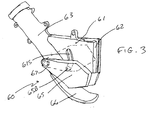
- FIG. 3 is a perspective view of a dust collector according to the invention.
- The invention is now described with reference to the accompanying figures, wherein like numerals designate like parts. Referring to FIG. 1, a combination table/
miter saw 100 may include abase assembly 10, a table 11 supported bybase assembly 10, and asaw assembly 20 supported by the table 11.Saw assembly 20 may include atrunnion 21 disposed on the table 11, apivotable arm 22 pivotably attached totrunnion 21, amotor 24 supported by thearm 22 and driving ablade 23.Arm 22 also supportsupper blade guard 27, which covers an upper part ofblade 23.Lower blade guard 25 is pivotally attached toupper blade guard 27. Anauxiliary blade guard 26 may be pivotably connected tolower blade guard 25. - Preferably, table 11 is pivotally attached to
base assembly 10 viajoint 15 so that, when the table 11 is in the orientation of FIG. 1A, thesaw assembly 20 can act as a miter saw, i.e., sawassembly 20 can be pivoted downwardly towards table 11 to cut a workpiece placed on table 11. The user can use ahandle 50 disposed on saw assembly 20 (e.g., onarm 22 and/or upper blade guard 27) topivot saw assembly 20 downwardly towards table 11. - On the other hand, when table 11 is rotated via
joint 15 to the orientation of FIG. 1B, the saw 100 acts as a table saw, i.e., sawassembly 20 will be supported by and disposed underneath the table 11. In such orientation,blade 23 extends through the table 11, so that a user can dispose a workpiece on table 11 and push it towardsblade 23 for cutting. - Persons skilled in the art will recognize that the invention described below can be applicable to non-combined miter saws.
- Preferably,
base assembly 10 has at least onewheel 13 thereon. -
Base assembly 10 may also support fourleg assemblies 30. Preferablyleg assemblies 30 are pivotally attached tobase assembly 10. - Referring to FIGS. 1-2,
lower blade guard 25 is pivotally connected toupper blade guard 27 atpivot junction 25P.Auxiliary blade guard 26 is pivotally connected tolower blade guard 25 at pivot junction 26P. - A
link 28 is pivotally connected at one end totrunnion 21 and to lowerblade guard 25 at the other end. Preferablylink 28 is made of metal. It is preferable thatlink 28 be pivotally connected tolower blade guard 25 at apivot junction 28P.Pivot junction 25P is preferably disposed between the point intrunnion 21 connected tolink 28 andpivot junction 28P. Furthermore,pivot junction 25P is preferably disposed underneath a line drawn between the point intrunnion 21 connected tolink 28 andpivot junction 28P. - With such arrangement, when the
saw assembly 20 is moved downwardly towards table 11,link 28 will pulllower blade guard 25, exposingblade 23 for the cutting operation. - An
auxiliary link 29 is pivotally connected at one end to link 28 and toauxiliary blade guard 26 at the other end. Preferablyauxiliary link 29 is made of metal. It is preferable thatauxiliary link 29 be pivotally connected toauxiliary blade guard 25 at a pivot junction 29P. Pivot junction 26P is preferably disposed between the point inauxiliary link 29 connected tolink 28 and pivot junction 29P. Furthermore, pivot junction 26P is preferably disposed underneath a line drawn between the point inauxiliary link 29 connected tolink 28 and pivot junction 29P. - Persons skilled in the art will recognize that it is also preferable that pivot junction 26P be disposed between
pivot junctions 25P and 29P. Furthermore, pivot junction 26P is preferably disposed underneath a line drawn between thepivot junctions 25P and 29P. - Similarly,
pivot junction 28P is preferably disposed between the point inauxiliary link 29 connected tolink 28 and pivot junction 29P. Furthermore,pivot junction 28P is preferably disposed underneath a line drawn between the point inauxiliary link 29 connected tolink 28 and pivot junction 29P. - With such arrangement,
auxiliary blade guard 26 will move aslower blade guard 25 is rotating to expose theblade 23. - Preferably
lower blade guard 25 moves overupper blade guard 27 and underneathauxiliary blade guard 26 when rotating. - Having such blade guard assembly covers more periphery of the
blade 23 when thesaw assembly 20 is in the upper position, while exposing more periphery of blade 23 (thus increasing cutting capacity) when thesaw assembly 20 is in the lower position. - A
handle 35 may be rotatably attached tolink 28. Apull link 36 may be pivotally attached to handle 35 at one end and toauxiliary link 29 at the other end. With such arrangement, the user can rotatehandle 35 to liftauxiliary blade guard 26 and/orlower blade guard 25. - This is especially useful when
saw 100 is being used in table saw mode, aslower blade guard 25 and/orauxiliary blade guard 26 may be contacting the underside of table 11.Lower blade guard 25 and/orauxiliary blade guard 26 may preventsaw assembly 20 from beveling. The user can reach underneath table 11, pullhandle 35, liftingauxiliary blade guard 26 and/orlower blade guard 25, allowing thesaw assembly 20 to bevel. - Referring to FIG. 2B, an
uplock assembly 40 may be provided onupper blade guard 27 to preventsaw assembly 20 from pivoting downwardly towards table 11 when saw 100 is being used in miter saw mode.Uplock assembly 40 may include alever 41 disposed nearhandle 50 and pivotably connected toupper blade guard 27, aguard lock 43 pivotably attached toupper blade guard 27 and rotatable between a first position engaginglower blade guard 25 and a second position not engaginglower blade guard 25, and alink 42 connected to lever 41 at one end and to guardlock 43 at the other end. - With such arrangement, the user would need to rotate
lever 41 towardshandle 50, causingguard lock 43 to rotate towards the second position, i.e., away fromlower blade guard 25, allowinglower blade guard 43 to rotate and thus allowing sawassembly 20 to rotate downwardly. If the user does not rotatelever 41 as described above,guard lock 43 will engagelower blade guard 25, not allowinglower blade guard 25 to rotate and not allowing sawassembly 20 to rotate downwardly. - Persons skilled in the art will recognize that
guard lock 43 may be designed to engageauxiliary blade guard 26 instead of or in addition tolower blade guard 25, and yet achieve the same result, i.e., not allowing sawassembly 20 to rotate downwardly untilguard lock 43 is moved to the second position. - Persons skilled in the art will also recognize that a spring (not shown) should be provided to bias
guard lock 43 towards the first position. Similarly, a spring (not shown) can be provided to lever 41 to bias it away fromhandle 50. - Because
lower blade guard 25 typically does not contactarm 22, a rear guard is typically provided betweenarm 22 andlower blade guard 25 to cover the periphery ofblade 23 therebetween.Dust duct assembly 60 is preferably provided onarm 22 to replace the typical rear guard. - Referring to FIGS. 1-3,
dust duct assembly 60 may have twowalls 61 substantially parallel toblade 23. Thesewalls 61 are connected to adust duct 63. Persons skilled in the art will recognize thatwalls 61 preferably define a chamber therebetween that is connected to a dust exhaust channel withindust duct 63. Preferably part of the periphery ofblade 23 extends into such chamber. - Each
wall 61 may have asecondary wall 62 extending towardsblade 23.Secondary walls 62 may act as blade calipers, limiting the sideways motion ofblade 23. Alternatively,secondary walls 62 may contact the body ofblade 23 before the blade's teeth contactupper blade guard 27,lower blade guard 25 and/orauxialiary blade guard 26. Persons skilled in the art will recognize secondary walls will not necessarily lower the amount of dust received by the chamber (and/or by dust duct 63) as the blade periphery is preferably disposed between thedust duct 63 and thesecondary walls 62. -
Dust duct 63 may extend past and/or througharm 22, and may be connected to a hose connected to a vacuum source, or to anelbow 64 for redirecting the flow of dust moving throughdust duct 63. Preferablydust duct 63 extends past, rather than through,arm 22. In thismanner dust duct 63 does not interfere with the spring (not shown) biasing arm 22 (and saw assembly 20) to the upper position. - It is preferable to provide
walls 65 pivotably attached todust duct 63. Alternativelywalls 65 may be pivotably attached towalls 61. Preferably awall 65 is disposed adjacent to awall 61 and/or on each side ofdust duct 63. Bothwalls 65 may be connected via aboss 65B.Boss 65B may travel along an arcuate slot 61 S disposed on bothwalls 61. - With such arrangement,
movable walls 65 can pivot from a lower position to an upper position. Preferably, at least onespring 67biases walls 65 towards the lower position.Walls 65 can pivot upwardly whenlower blade guard 25 is in the original position contacting walls 65 (see FIG. 2A).Walls 65 can also pivot upwardly when onewall 65 contacts afence 16 during a beveling operation. - A
resilient flap 66 may be connected todust duct 63. Preferablyflap 66 is disposed underneathwalls walls 61. - Persons skilled in the art will recognize that
dust duct 63 and/orwalls 61 may be attached toarm 22. - Persons skilled in the art may recognize other additions or alternatives to the means disclosed herein. However, all these additions and/or alterations are considered to be equivalents of the present invention.
Claims (18)
- A power tool comprising:a base assembly;a table supported by the base assembly;a saw assembly pivotally attached to the table via a trunnion, the saw assembly including a motor, a blade driven by the motor, an upper blade guard covering an upper part of the blade, a lower blade guard pivotally attached to the upper blade guard for covering a lower part of the blade, an auxiliary blade guard pivotally attached to the lower blade guard, a first link attached at one end to the trunnion and at the other end to the lower blade guard, an auxiliary link attached at one end to the first link and at the other end to the auxiliary blade guard; andan uplock assembly comprising a guard lock movable between a first position contacting the lower blade guard and a second position not contacting the lower blade guard.
- The power tool of Claim 1, wherein the uplock assembly further comprises a lever attached to the upper blade guard and connected to the guard lock.
- The power tool of Claim 2, wherein the saw assembly further comprises a handle, the lever being pivotally attached to the upper blade guard adjacent to the handle.
- The power tool of Claim 2, wherein the lever is connected to the guard lock via a second link.
- The power tool of Claim 1, wherein the guard lock is pivotably attached to the upper blade guard.
- The power tool of Claim 1, further comprising a handle pivotably attached to the first link.
- The power tool of Claim 6, further comprising a second link attached at one end to the handle and to the auxiliary link at the other end.
- The power tool of Claim 1, wherein the table is pivotably supported by the base assembly.
- The power tool of Claim 8, wherein the table pivots about a horizontal axis.
- A power tool comprising:a base assembly;a table supported by the base assembly;a saw assembly pivotally attached to the table via a trunnion, the saw assembly including a motor, a blade driven by the motor, an upper blade guard covering an upper part of the blade, and a dust duct disposed between the trunnion and the upper blade guard;wherein the dust duct comprises first and second walls pivotably attached to the dust duct, and a resilient flap attached to the dust duct disposed underneath the first and second walls.
- The power tool of Claim 10, wherein the dust duct further comprises third and fourth walls attached to the dust duct.
- The power tool of Claim 11, wherin the first and second walls are pivotably attached to the third and fourth walls, respectively.
- The power tool of Claim 11, wherein the third and fourth walls are disposed on each side of the blade, respectively.
- The power tool of Claim 10, wherein the first and second walls are disposed on each side of the blade, respectively.
- The power tool of Claim 10, further comprising a fence disposed above the table.
- The power tool of Claim 15, wherein at least one of the first and second walls can contact the fence.
- The power tool of Claim 10, wherein the table is pivotably supported by the base assembly.
- The power tool of Claim 17, wherein the table pivots about a horizontal axis.
Priority Applications (1)
| Application Number | Priority Date | Filing Date | Title |
|---|---|---|---|
| EP07111827A EP1852227B1 (en) | 2004-07-07 | 2005-06-30 | Blade guard assembly for a saw |
Applications Claiming Priority (1)
| Application Number | Priority Date | Filing Date | Title |
|---|---|---|---|
| US58603904P | 2004-07-07 | 2004-07-07 |
Related Child Applications (1)
| Application Number | Title | Priority Date | Filing Date |
|---|---|---|---|
| EP07111827A Division EP1852227B1 (en) | 2004-07-07 | 2005-06-30 | Blade guard assembly for a saw |
Publications (3)
| Publication Number | Publication Date |
|---|---|
| EP1614511A1 true EP1614511A1 (en) | 2006-01-11 |
| EP1614511A3 EP1614511A3 (en) | 2006-05-10 |
| EP1614511B1 EP1614511B1 (en) | 2008-12-31 |
Family
ID=35106727
Family Applications (1)
| Application Number | Title | Priority Date | Filing Date |
|---|---|---|---|
| EP20050014124 Expired - Lifetime EP1614511B1 (en) | 2004-07-07 | 2005-06-30 | Blade guard assembly for a saw |
Country Status (7)
| Country | Link |
|---|---|
| US (1) | US20060005681A1 (en) |
| EP (1) | EP1614511B1 (en) |
| CN (1) | CN100553837C (en) |
| AT (1) | ATE419099T1 (en) |
| AU (2) | AU2005202871B2 (en) |
| DE (1) | DE602005012025D1 (en) |
| TW (1) | TWI362990B (en) |
Cited By (5)
| Publication number | Priority date | Publication date | Assignee | Title |
|---|---|---|---|---|
| DE102008045838A1 (en) * | 2008-09-05 | 2010-04-15 | Tünnissen, Werner | Equipment for treatment of ground area, particularly tree stump grinder, has driven milling wheel which is enclosed partially by protective housing, where protective housing has multiple, particularly two partial housings |
| CN102218756A (en) * | 2010-04-15 | 2011-10-19 | 株式会社牧田 | Cutting devices |
| GB2507943A (en) * | 2012-07-23 | 2014-05-21 | Black & Decker Inc | Dust removal for Saw |
| EP3330028A1 (en) * | 2016-11-30 | 2018-06-06 | Metabowerke GmbH | Machine tool with dust collecting device |
| EP2969333B1 (en) * | 2013-03-15 | 2019-09-25 | Robert Bosch GmbH | Miter saw rear guard |
Families Citing this family (20)
| Publication number | Priority date | Publication date | Assignee | Title |
|---|---|---|---|---|
| AU2007200238B9 (en) * | 2006-01-31 | 2012-06-14 | Black & Decker Inc | Saw |
| US7752951B2 (en) * | 2006-09-18 | 2010-07-13 | Normand Ouellette | Convertible circular saw apparatus usable as either a miter saw or a table saw |
| JP5179232B2 (en) * | 2008-03-21 | 2013-04-10 | 株式会社マキタ | Tabletop cutting machine |
| US8702478B2 (en) * | 2009-05-08 | 2014-04-22 | Michael Loveless | Angle grinder dust shroud with unitary adjustable mounting collar |
| US8523637B2 (en) * | 2009-07-21 | 2013-09-03 | Dustless Depot, Llc | Angle grinder dust shroud with slideable access hatch |
| US8561512B2 (en) * | 2009-08-18 | 2013-10-22 | Dustless Depot Llc | Cutoff saw and stand with integrated dust filtration system |
| GB201003262D0 (en) * | 2010-02-26 | 2010-04-14 | 7Rdd Ltd | Saw guard means and method of use thereof |
| US9038275B2 (en) | 2011-09-07 | 2015-05-26 | Dustless Depot, Llc | Reciprocating saw dust shroud |
| CN102814700A (en) * | 2012-09-22 | 2012-12-12 | 无锡华联精工机械有限公司 | Milling cover structure for circular-seam back-chipping edge milling machine |
| CN203141594U (en) * | 2013-01-29 | 2013-08-21 | 何财柏 | Dual-purpose electric saw |
| US9283628B2 (en) | 2013-03-08 | 2016-03-15 | Black & Decker Inc. | Chop saw with improved storage mode |
| WO2016093140A1 (en) | 2014-12-09 | 2016-06-16 | 雫石 誠 | Imaging device |
| US10882123B2 (en) | 2015-02-25 | 2021-01-05 | Milwaukee Electric Tool Corporation | Miter saw |
| CN105235029A (en) * | 2015-10-29 | 2016-01-13 | 浙江培瑞工具有限公司 | Protective cover for bench saw |
| USD816453S1 (en) | 2016-09-15 | 2018-05-01 | Dustless Depot, Llc | Circular saw dust shroud |
| US10293421B2 (en) | 2016-09-15 | 2019-05-21 | Dustless Depot, Llc | Circular saw dust collection shroud |
| USD908149S1 (en) | 2018-10-23 | 2021-01-19 | Dustless Depot Llc | Angle grinder dust shroud with variable position slots for mounting brackets |
| US11123839B2 (en) | 2018-10-23 | 2021-09-21 | Dustless Depot Llc | Grinder dust shroud with input shaft gasket and adjustable mounting mechanism |
| US11273505B2 (en) | 2019-03-27 | 2022-03-15 | Dustless Depot, Llc | Circular saw dust collection shroud |
| CN224103119U (en) * | 2024-08-24 | 2026-04-10 | 俐申智能科技(永康)有限公司 | Table type chain saw |
Citations (4)
| Publication number | Priority date | Publication date | Assignee | Title |
|---|---|---|---|---|
| EP0450400A1 (en) * | 1990-03-31 | 1991-10-09 | Elektra Beckum Aktiengesellschaft | Sawing device with pivoting protective hood attached to a saw unit |
| EP0586172A2 (en) * | 1992-08-28 | 1994-03-09 | Black & Decker Inc. | Pivoting power tool with table |
| US5950514A (en) * | 1997-02-28 | 1999-09-14 | Benedict Engineering Company | Miter saw blade guards |
| US20020134211A1 (en) * | 1999-02-27 | 2002-09-26 | Marcello Bettacchini | Locking arrangement for table saw guard |
Family Cites Families (18)
| Publication number | Priority date | Publication date | Assignee | Title |
|---|---|---|---|---|
| US3322169A (en) * | 1964-08-03 | 1967-05-30 | Floyd T Hilliard | Sawdust collecting means for radial saws |
| US5167215A (en) * | 1991-10-11 | 1992-12-01 | Equipment Development Co., Inc. | Dust removal apparatus for a concrete saw |
| GB9225441D0 (en) * | 1992-12-04 | 1993-01-27 | Black & Decker Inc | A saw |
| JP3431347B2 (en) * | 1995-06-05 | 2003-07-28 | 株式会社マキタ | Tabletop circular saw machine |
| US5755148A (en) * | 1995-07-07 | 1998-05-26 | Black & Decker Inc. | Adjustable fence for a compound miter saw |
| GB2304075B (en) * | 1995-08-10 | 1999-10-20 | Milwaukee Electric Tool Corp | Indexing override mechanism for a slide compound miter saw |
| CN2269282Y (en) * | 1996-08-14 | 1997-12-03 | 郑春隆 | Cutting machine safety cover interlocking structure |
| CA2285638A1 (en) * | 1999-07-26 | 2001-01-26 | Louis C. Brickner, Jr. | Improved dust collection system |
| CA2302032C (en) * | 1999-07-28 | 2007-06-12 | Black & Decker Inc. | Miter saw |
| US6742425B2 (en) * | 2001-06-14 | 2004-06-01 | Black & Decker Inc. | Dust collector |
| US6557261B1 (en) * | 2001-08-21 | 2003-05-06 | John P. Buser | Dust-capturing adaptor for a saw |
| US6748660B2 (en) * | 2002-05-15 | 2004-06-15 | John P. Buser | Debris-collection device for a power saw |
| US20040020342A1 (en) * | 2002-08-02 | 2004-02-05 | Wattenbach Brian P. | Fence protection arrangement for a slide miter saw |
| CN2565572Y (en) * | 2002-08-12 | 2003-08-13 | 宁波经济技术开发区中强电动工具有限公司 | Self locking device of bias cutter protective hood |
| US20040103769A1 (en) * | 2002-09-17 | 2004-06-03 | Parks James R. | Dust collection arrangement for a miter saw |
| TW569907U (en) * | 2002-09-26 | 2004-01-01 | P & F Brother Ind Corp | Dust collecting structure for supporting seat of cutting machine |
| DE202004000983U1 (en) * | 2004-01-22 | 2005-03-10 | Metabowerke Gmbh | Chop saw with dust catcher |
| US7069831B2 (en) * | 2004-08-18 | 2006-07-04 | Chin-Chin Chang | Sawdust collection system for a circular saw |
-
2005
- 2005-06-30 EP EP20050014124 patent/EP1614511B1/en not_active Expired - Lifetime
- 2005-06-30 DE DE200560012025 patent/DE602005012025D1/en not_active Expired - Lifetime
- 2005-06-30 AT AT05014124T patent/ATE419099T1/en not_active IP Right Cessation
- 2005-06-30 AU AU2005202871A patent/AU2005202871B2/en not_active Ceased
- 2005-07-06 US US11/175,739 patent/US20060005681A1/en not_active Abandoned
- 2005-07-07 CN CNB2005100913453A patent/CN100553837C/en not_active Expired - Fee Related
- 2005-07-07 TW TW94123048A patent/TWI362990B/en not_active IP Right Cessation
-
2010
- 2010-04-28 AU AU2010201686A patent/AU2010201686B2/en not_active Ceased
Patent Citations (4)
| Publication number | Priority date | Publication date | Assignee | Title |
|---|---|---|---|---|
| EP0450400A1 (en) * | 1990-03-31 | 1991-10-09 | Elektra Beckum Aktiengesellschaft | Sawing device with pivoting protective hood attached to a saw unit |
| EP0586172A2 (en) * | 1992-08-28 | 1994-03-09 | Black & Decker Inc. | Pivoting power tool with table |
| US5950514A (en) * | 1997-02-28 | 1999-09-14 | Benedict Engineering Company | Miter saw blade guards |
| US20020134211A1 (en) * | 1999-02-27 | 2002-09-26 | Marcello Bettacchini | Locking arrangement for table saw guard |
Cited By (7)
| Publication number | Priority date | Publication date | Assignee | Title |
|---|---|---|---|---|
| DE102008045838A1 (en) * | 2008-09-05 | 2010-04-15 | Tünnissen, Werner | Equipment for treatment of ground area, particularly tree stump grinder, has driven milling wheel which is enclosed partially by protective housing, where protective housing has multiple, particularly two partial housings |
| DE102008045838B4 (en) * | 2008-09-05 | 2010-12-30 | Tünnisssen Spezialmaschinen GmbH | Device for processing a floor area |
| CN102218756A (en) * | 2010-04-15 | 2011-10-19 | 株式会社牧田 | Cutting devices |
| US9021930B2 (en) | 2010-04-15 | 2015-05-05 | Makita Corporation | Cutting devices |
| GB2507943A (en) * | 2012-07-23 | 2014-05-21 | Black & Decker Inc | Dust removal for Saw |
| EP2969333B1 (en) * | 2013-03-15 | 2019-09-25 | Robert Bosch GmbH | Miter saw rear guard |
| EP3330028A1 (en) * | 2016-11-30 | 2018-06-06 | Metabowerke GmbH | Machine tool with dust collecting device |
Also Published As
| Publication number | Publication date |
|---|---|
| AU2010201686A1 (en) | 2010-05-20 |
| TWI362990B (en) | 2012-05-01 |
| CN1718340A (en) | 2006-01-11 |
| CN100553837C (en) | 2009-10-28 |
| AU2005202871B2 (en) | 2010-05-27 |
| EP1614511A3 (en) | 2006-05-10 |
| ATE419099T1 (en) | 2009-01-15 |
| TW200618971A (en) | 2006-06-16 |
| EP1614511B1 (en) | 2008-12-31 |
| DE602005012025D1 (en) | 2009-02-12 |
| US20060005681A1 (en) | 2006-01-12 |
| AU2010201686B2 (en) | 2013-02-28 |
| AU2005202871A1 (en) | 2006-02-02 |
Similar Documents
| Publication | Publication Date | Title |
|---|---|---|
| AU2010201686B2 (en) | Dust collector for saws | |
| US6510772B2 (en) | Dust collection system | |
| CN100358660C (en) | Miter saw | |
| AU2005202873B2 (en) | Fence assembly for miter saws | |
| EP1852227B1 (en) | Blade guard assembly for a saw | |
| EP1380395B1 (en) | Chop saw | |
| AU2005202908B2 (en) | Miter lock assembly for miter saws | |
| US20060107810A1 (en) | Mitre saw | |
| EP1623800A1 (en) | Table latch assembly for saws | |
| AU2005202884B2 (en) | Table assembly for miter saws | |
| JP3215966B2 (en) | Sliding desk circular saw machine | |
| AU2005202982B2 (en) | Depth control mechanism for table saw | |
| EP1621276A1 (en) | Miter saw arrangement for increased cutting capacity | |
| JPH0857808A (en) | Bench circular sawing machine | |
| JPH0551602U (en) | Movable guard opening / closing mechanism for portable dust collecting circular saw | |
| JP2009095983A (en) | Sliding cutter |
Legal Events
| Date | Code | Title | Description |
|---|---|---|---|
| PUAI | Public reference made under article 153(3) epc to a published international application that has entered the european phase |
Free format text: ORIGINAL CODE: 0009012 |
|
| AK | Designated contracting states |
Kind code of ref document: A1 Designated state(s): AT BE BG CH CY CZ DE DK EE ES FI FR GB GR HU IE IS IT LI LT LU MC NL PL PT RO SE SI SK TR |
|
| AX | Request for extension of the european patent |
Extension state: AL BA HR LV MK YU |
|
| PUAB | Information related to the publication of an a document modified or deleted |
Free format text: ORIGINAL CODE: 0009199EPPU |
|
| PUAF | Information related to the publication of a search report (a3 document) modified or deleted |
Free format text: ORIGINAL CODE: 0009199SEPU |
|
| PUAL | Search report despatched |
Free format text: ORIGINAL CODE: 0009013 |
|
| D17D | Deferred search report published (deleted) | ||
| RA1 | Application published (corrected) |
Date of ref document: 20060111 Kind code of ref document: A2 |
|
| 17P | Request for examination filed |
Effective date: 20060316 |
|
| AK | Designated contracting states |
Kind code of ref document: A3 Designated state(s): AT BE BG CH CY CZ DE DK EE ES FI FR GB GR HU IE IS IT LI LT LU MC NL PL PT RO SE SI SK TR |
|
| AX | Request for extension of the european patent |
Extension state: AL BA HR LV MK YU |
|
| AKX | Designation fees paid |
Designated state(s): AT BE BG CH CY CZ DE DK EE ES FI FR GB GR HU IE IS IT LI LT LU MC NL PL PT RO SE SI SK TR |
|
| 17Q | First examination report despatched |
Effective date: 20070307 |
|
| REG | Reference to a national code |
Ref country code: SE Ref legal event code: TRGR |
|
| GRAP | Despatch of communication of intention to grant a patent |
Free format text: ORIGINAL CODE: EPIDOSNIGR1 |
|
| GRAS | Grant fee paid |
Free format text: ORIGINAL CODE: EPIDOSNIGR3 |
|
| GRAA | (expected) grant |
Free format text: ORIGINAL CODE: 0009210 |
|
| AK | Designated contracting states |
Kind code of ref document: B1 Designated state(s): AT BE BG CH CY CZ DE DK EE ES FI FR GB GR HU IE IS IT LI LT LU MC NL PL PT RO SE SI SK TR |
|
| REG | Reference to a national code |
Ref country code: GB Ref legal event code: FG4D Ref country code: CH Ref legal event code: EP |
|
| REF | Corresponds to: |
Ref document number: 602005012025 Country of ref document: DE Date of ref document: 20090212 Kind code of ref document: P |
|
| REG | Reference to a national code |
Ref country code: IE Ref legal event code: FG4D |
|
| PG25 | Lapsed in a contracting state [announced via postgrant information from national office to epo] |
Ref country code: SI Free format text: LAPSE BECAUSE OF FAILURE TO SUBMIT A TRANSLATION OF THE DESCRIPTION OR TO PAY THE FEE WITHIN THE PRESCRIBED TIME-LIMIT Effective date: 20081231 Ref country code: PL Free format text: LAPSE BECAUSE OF FAILURE TO SUBMIT A TRANSLATION OF THE DESCRIPTION OR TO PAY THE FEE WITHIN THE PRESCRIBED TIME-LIMIT Effective date: 20081231 Ref country code: FI Free format text: LAPSE BECAUSE OF FAILURE TO SUBMIT A TRANSLATION OF THE DESCRIPTION OR TO PAY THE FEE WITHIN THE PRESCRIBED TIME-LIMIT Effective date: 20081231 Ref country code: NL Free format text: LAPSE BECAUSE OF FAILURE TO SUBMIT A TRANSLATION OF THE DESCRIPTION OR TO PAY THE FEE WITHIN THE PRESCRIBED TIME-LIMIT Effective date: 20081231 |
|
| NLV1 | Nl: lapsed or annulled due to failure to fulfill the requirements of art. 29p and 29m of the patents act | ||
| PG25 | Lapsed in a contracting state [announced via postgrant information from national office to epo] |
Ref country code: LT Free format text: LAPSE BECAUSE OF FAILURE TO SUBMIT A TRANSLATION OF THE DESCRIPTION OR TO PAY THE FEE WITHIN THE PRESCRIBED TIME-LIMIT Effective date: 20081231 Ref country code: ES Free format text: LAPSE BECAUSE OF FAILURE TO SUBMIT A TRANSLATION OF THE DESCRIPTION OR TO PAY THE FEE WITHIN THE PRESCRIBED TIME-LIMIT Effective date: 20090411 Ref country code: RO Free format text: LAPSE BECAUSE OF FAILURE TO SUBMIT A TRANSLATION OF THE DESCRIPTION OR TO PAY THE FEE WITHIN THE PRESCRIBED TIME-LIMIT Effective date: 20081231 Ref country code: BE Free format text: LAPSE BECAUSE OF FAILURE TO SUBMIT A TRANSLATION OF THE DESCRIPTION OR TO PAY THE FEE WITHIN THE PRESCRIBED TIME-LIMIT Effective date: 20081231 Ref country code: EE Free format text: LAPSE BECAUSE OF FAILURE TO SUBMIT A TRANSLATION OF THE DESCRIPTION OR TO PAY THE FEE WITHIN THE PRESCRIBED TIME-LIMIT Effective date: 20081231 |
|
| PG25 | Lapsed in a contracting state [announced via postgrant information from national office to epo] |
Ref country code: CZ Free format text: LAPSE BECAUSE OF FAILURE TO SUBMIT A TRANSLATION OF THE DESCRIPTION OR TO PAY THE FEE WITHIN THE PRESCRIBED TIME-LIMIT Effective date: 20081231 Ref country code: AT Free format text: LAPSE BECAUSE OF FAILURE TO SUBMIT A TRANSLATION OF THE DESCRIPTION OR TO PAY THE FEE WITHIN THE PRESCRIBED TIME-LIMIT Effective date: 20081231 Ref country code: IS Free format text: LAPSE BECAUSE OF FAILURE TO SUBMIT A TRANSLATION OF THE DESCRIPTION OR TO PAY THE FEE WITHIN THE PRESCRIBED TIME-LIMIT Effective date: 20090430 Ref country code: PT Free format text: LAPSE BECAUSE OF FAILURE TO SUBMIT A TRANSLATION OF THE DESCRIPTION OR TO PAY THE FEE WITHIN THE PRESCRIBED TIME-LIMIT Effective date: 20090601 |
|
| PG25 | Lapsed in a contracting state [announced via postgrant information from national office to epo] |
Ref country code: SK Free format text: LAPSE BECAUSE OF FAILURE TO SUBMIT A TRANSLATION OF THE DESCRIPTION OR TO PAY THE FEE WITHIN THE PRESCRIBED TIME-LIMIT Effective date: 20081231 |
|
| PG25 | Lapsed in a contracting state [announced via postgrant information from national office to epo] |
Ref country code: DK Free format text: LAPSE BECAUSE OF FAILURE TO SUBMIT A TRANSLATION OF THE DESCRIPTION OR TO PAY THE FEE WITHIN THE PRESCRIBED TIME-LIMIT Effective date: 20081231 |
|
| PLBE | No opposition filed within time limit |
Free format text: ORIGINAL CODE: 0009261 |
|
| STAA | Information on the status of an ep patent application or granted ep patent |
Free format text: STATUS: NO OPPOSITION FILED WITHIN TIME LIMIT |
|
| 26N | No opposition filed |
Effective date: 20091001 |
|
| PG25 | Lapsed in a contracting state [announced via postgrant information from national office to epo] |
Ref country code: BG Free format text: LAPSE BECAUSE OF FAILURE TO SUBMIT A TRANSLATION OF THE DESCRIPTION OR TO PAY THE FEE WITHIN THE PRESCRIBED TIME-LIMIT Effective date: 20090331 Ref country code: MC Free format text: LAPSE BECAUSE OF NON-PAYMENT OF DUE FEES Effective date: 20090630 |
|
| REG | Reference to a national code |
Ref country code: CH Ref legal event code: PL |
|
| REG | Reference to a national code |
Ref country code: IE Ref legal event code: MM4A |
|
| PG25 | Lapsed in a contracting state [announced via postgrant information from national office to epo] |
Ref country code: LI Free format text: LAPSE BECAUSE OF NON-PAYMENT OF DUE FEES Effective date: 20090630 Ref country code: CH Free format text: LAPSE BECAUSE OF NON-PAYMENT OF DUE FEES Effective date: 20090630 Ref country code: IE Free format text: LAPSE BECAUSE OF NON-PAYMENT OF DUE FEES Effective date: 20090630 |
|
| PGFP | Annual fee paid to national office [announced via postgrant information from national office to epo] |
Ref country code: FR Payment date: 20091201 Year of fee payment: 5 |
|
| PG25 | Lapsed in a contracting state [announced via postgrant information from national office to epo] |
Ref country code: GR Free format text: LAPSE BECAUSE OF FAILURE TO SUBMIT A TRANSLATION OF THE DESCRIPTION OR TO PAY THE FEE WITHIN THE PRESCRIBED TIME-LIMIT Effective date: 20090401 |
|
| REG | Reference to a national code |
Ref country code: FR Ref legal event code: ST Effective date: 20110228 |
|
| PG25 | Lapsed in a contracting state [announced via postgrant information from national office to epo] |
Ref country code: LU Free format text: LAPSE BECAUSE OF NON-PAYMENT OF DUE FEES Effective date: 20090630 |
|
| PG25 | Lapsed in a contracting state [announced via postgrant information from national office to epo] |
Ref country code: FR Free format text: LAPSE BECAUSE OF NON-PAYMENT OF DUE FEES Effective date: 20100630 |
|
| PG25 | Lapsed in a contracting state [announced via postgrant information from national office to epo] |
Ref country code: HU Free format text: LAPSE BECAUSE OF FAILURE TO SUBMIT A TRANSLATION OF THE DESCRIPTION OR TO PAY THE FEE WITHIN THE PRESCRIBED TIME-LIMIT Effective date: 20090701 |
|
| PG25 | Lapsed in a contracting state [announced via postgrant information from national office to epo] |
Ref country code: TR Free format text: LAPSE BECAUSE OF FAILURE TO SUBMIT A TRANSLATION OF THE DESCRIPTION OR TO PAY THE FEE WITHIN THE PRESCRIBED TIME-LIMIT Effective date: 20081231 |
|
| PG25 | Lapsed in a contracting state [announced via postgrant information from national office to epo] |
Ref country code: CY Free format text: LAPSE BECAUSE OF FAILURE TO SUBMIT A TRANSLATION OF THE DESCRIPTION OR TO PAY THE FEE WITHIN THE PRESCRIBED TIME-LIMIT Effective date: 20081231 |
|
| PGFP | Annual fee paid to national office [announced via postgrant information from national office to epo] |
Ref country code: DE Payment date: 20180619 Year of fee payment: 14 |
|
| PGFP | Annual fee paid to national office [announced via postgrant information from national office to epo] |
Ref country code: SE Payment date: 20180612 Year of fee payment: 14 |
|
| PGFP | Annual fee paid to national office [announced via postgrant information from national office to epo] |
Ref country code: GB Payment date: 20180627 Year of fee payment: 14 Ref country code: IT Payment date: 20180625 Year of fee payment: 14 |
|
| REG | Reference to a national code |
Ref country code: DE Ref legal event code: R119 Ref document number: 602005012025 Country of ref document: DE |
|
| GBPC | Gb: european patent ceased through non-payment of renewal fee |
Effective date: 20190630 |
|
| REG | Reference to a national code |
Ref country code: SE Ref legal event code: EUG |
|
| PG25 | Lapsed in a contracting state [announced via postgrant information from national office to epo] |
Ref country code: SE Free format text: LAPSE BECAUSE OF NON-PAYMENT OF DUE FEES Effective date: 20190701 Ref country code: IT Free format text: LAPSE BECAUSE OF NON-PAYMENT OF DUE FEES Effective date: 20190630 Ref country code: DE Free format text: LAPSE BECAUSE OF NON-PAYMENT OF DUE FEES Effective date: 20200101 Ref country code: GB Free format text: LAPSE BECAUSE OF NON-PAYMENT OF DUE FEES Effective date: 20190630 |