EP1614468A1 - Drip-less pipetting device and the mode of operation - Google Patents
Drip-less pipetting device and the mode of operation Download PDFInfo
- Publication number
- EP1614468A1 EP1614468A1 EP04015682A EP04015682A EP1614468A1 EP 1614468 A1 EP1614468 A1 EP 1614468A1 EP 04015682 A EP04015682 A EP 04015682A EP 04015682 A EP04015682 A EP 04015682A EP 1614468 A1 EP1614468 A1 EP 1614468A1
- Authority
- EP
- European Patent Office
- Prior art keywords
- liquid
- gas pressure
- vessel
- gas
- drive
- Prior art date
- Legal status (The legal status is an assumption and is not a legal conclusion. Google has not performed a legal analysis and makes no representation as to the accuracy of the status listed.)
- Granted
Links
- 239000007788 liquid Substances 0.000 claims abstract description 128
- 238000000034 method Methods 0.000 claims abstract description 33
- 230000033001 locomotion Effects 0.000 claims description 58
- 230000008859 change Effects 0.000 claims description 19
- 238000001514 detection method Methods 0.000 claims description 16
- 239000012530 fluid Substances 0.000 claims description 16
- 230000008569 process Effects 0.000 claims description 15
- 230000001105 regulatory effect Effects 0.000 claims description 2
- 239000007789 gas Substances 0.000 description 107
- 230000008020 evaporation Effects 0.000 description 6
- 238000001704 evaporation Methods 0.000 description 6
- 230000000694 effects Effects 0.000 description 5
- 230000001419 dependent effect Effects 0.000 description 4
- 230000004044 response Effects 0.000 description 4
- 230000008901 benefit Effects 0.000 description 3
- 230000007423 decrease Effects 0.000 description 3
- IJGRMHOSHXDMSA-UHFFFAOYSA-N Atomic nitrogen Chemical compound N#N IJGRMHOSHXDMSA-UHFFFAOYSA-N 0.000 description 2
- 230000004913 activation Effects 0.000 description 2
- 238000007599 discharging Methods 0.000 description 2
- OKTJSMMVPCPJKN-UHFFFAOYSA-N Carbon Chemical compound [C] OKTJSMMVPCPJKN-UHFFFAOYSA-N 0.000 description 1
- 230000003213 activating effect Effects 0.000 description 1
- 239000000853 adhesive Substances 0.000 description 1
- 230000001070 adhesive effect Effects 0.000 description 1
- 230000033228 biological regulation Effects 0.000 description 1
- 238000006243 chemical reaction Methods 0.000 description 1
- 230000001276 controlling effect Effects 0.000 description 1
- 230000003247 decreasing effect Effects 0.000 description 1
- 238000006073 displacement reaction Methods 0.000 description 1
- 230000007613 environmental effect Effects 0.000 description 1
- 230000006870 function Effects 0.000 description 1
- 238000010438 heat treatment Methods 0.000 description 1
- 230000014759 maintenance of location Effects 0.000 description 1
- 229910052757 nitrogen Inorganic materials 0.000 description 1
- 229910052756 noble gas Inorganic materials 0.000 description 1
- 239000002245 particle Substances 0.000 description 1
- 230000002265 prevention Effects 0.000 description 1
- 230000000630 rising effect Effects 0.000 description 1
- -1 temperature Substances 0.000 description 1
- XLYOFNOQVPJJNP-UHFFFAOYSA-N water Substances O XLYOFNOQVPJJNP-UHFFFAOYSA-N 0.000 description 1
Images


Classifications
-
- B—PERFORMING OPERATIONS; TRANSPORTING
- B01—PHYSICAL OR CHEMICAL PROCESSES OR APPARATUS IN GENERAL
- B01L—CHEMICAL OR PHYSICAL LABORATORY APPARATUS FOR GENERAL USE
- B01L3/00—Containers or dishes for laboratory use, e.g. laboratory glassware; Droppers
- B01L3/02—Burettes; Pipettes
- B01L3/021—Pipettes, i.e. with only one conduit for withdrawing and redistributing liquids
- B01L3/0217—Pipettes, i.e. with only one conduit for withdrawing and redistributing liquids of the plunger pump type
- B01L3/0227—Details of motor drive means
-
- B—PERFORMING OPERATIONS; TRANSPORTING
- B01—PHYSICAL OR CHEMICAL PROCESSES OR APPARATUS IN GENERAL
- B01L—CHEMICAL OR PHYSICAL LABORATORY APPARATUS FOR GENERAL USE
- B01L2200/00—Solutions for specific problems relating to chemical or physical laboratory apparatus
- B01L2200/06—Fluid handling related problems
- B01L2200/0615—Loss of fluid by dripping
-
- B—PERFORMING OPERATIONS; TRANSPORTING
- B01—PHYSICAL OR CHEMICAL PROCESSES OR APPARATUS IN GENERAL
- B01L—CHEMICAL OR PHYSICAL LABORATORY APPARATUS FOR GENERAL USE
- B01L2200/00—Solutions for specific problems relating to chemical or physical laboratory apparatus
- B01L2200/14—Process control and prevention of errors
- B01L2200/143—Quality control, feedback systems
- B01L2200/146—Employing pressure sensors
-
- B—PERFORMING OPERATIONS; TRANSPORTING
- B01—PHYSICAL OR CHEMICAL PROCESSES OR APPARATUS IN GENERAL
- B01L—CHEMICAL OR PHYSICAL LABORATORY APPARATUS FOR GENERAL USE
- B01L2200/00—Solutions for specific problems relating to chemical or physical laboratory apparatus
- B01L2200/14—Process control and prevention of errors
- B01L2200/148—Specific details about calibrations
-
- B—PERFORMING OPERATIONS; TRANSPORTING
- B01—PHYSICAL OR CHEMICAL PROCESSES OR APPARATUS IN GENERAL
- B01L—CHEMICAL OR PHYSICAL LABORATORY APPARATUS FOR GENERAL USE
- B01L2300/00—Additional constructional details
- B01L2300/02—Identification, exchange or storage of information
- B01L2300/024—Storing results with means integrated into the container
Definitions
- the present invention relates to a method for preventing drop losses in remplisstechniksdosiervortechniken.
- a device of the type mentioned is known from DE 44 21 303 A1.
- a pipetting device which sucks in or expels an amount of liquid into a portion of a pipetting tip. This is done by changing the gas pressure of a gas trapped between a piston, cylinder walls and the liquid.
- the pressure of the trapped gas and the prevailing ambient pressure are measured. From the measured values is under Taking into account the geometric shape of the cylinder and the pipette tip calculates a correction value in order to obtain as accurately as possible the distance to be traveled by the piston as a setpoint for the control of the Koblen Gay. The controller then initiates movement of the piston based on the corrected setpoint.
- DE 44 21 303 A1 be thought to monitor the pressure of the gas between the piston and the amount of liquid between the termination of the fluid intake and the beginning of the liquid delivery to determine leaks on the pipette or the like.
- WO 97/02893 A1 discloses a method and a device for correcting a temperature-dependent error during the metering of a liquid from a pipette.
- the known device comprises two chambers connected in series to one another by a gas passage, namely a first chamber in the pipetting tip and a second chamber in the piston-cylinder system to which the pipetting tip is connected.
- the pipetting tip which is provided with an opening, is immersed in it to absorb liquid.
- a vessel wall of the second chamber is formed by a movable piston.
- the second chamber is complete, the first chamber at least partially filled with a gas. The amount of gas is trapped between the piston and liquid in the two chambers.
- WO 97/02893 A1 proposes to measure the change in temperature of the gas flowing from the first to the second chamber when the liquid is taken up by the piston movement and the change in volume caused by the piston movement in the second chamber to correct based on the measured temperature change during the liquid acquisition process. This is provided at least one temperature sensor.
- the method known from WO 97/02893 A1 merely serves to correct the piston movement during fluid intake.
- EP 0 747 689 B1 shows an apparatus and a method for withdrawing a liquid from a tightly closed container.
- the tightly closed container contains a quantity of gas.
- the gas pressure inside the container is monitored by a pressure sensor. Before that, the gas pressure inside the sealed vessel is brought to ambient pressure by piercing the seal with a hollow needle.
- the present application is based on the following problem:
- the liquid In vessels in which an amount of liquid is delivered or received by varying the pressure of a gas trapped by vessel walls and the liquid, the liquid is kept in the vessel for a considerable time between a liquid receiving operation and a liquid discharging operation, such as to overcome transport routes. During this time, the pressure difference between the ambient pressure and the pressure of the trapped gas as well as frictional and adhesive forces acting between the liquid and the wetted wall maintain the liquid in the vessel. In this case, the pressure difference between the ambient pressure and the gas pressure in the interior of the vessel has the largest share of the force holding the liquid in the vessel.
- the pressure of the gas trapped in the vessel may change due to evaporation or due to temperature compensation processes.
- Evaporates for example, absorbed liquid, so the increases Gas pressure in the vessel.
- the gas pressure usually increases more than the weight of the not yet evaporated liquid decreases.
- the described processes can lead to the unwanted increased gas pressure, a part of the liquid absorbed amount is undesirably ejected from the vessel. The ejected liquid then drips off the vessel. As a result, undesirably erroneous amounts of liquid can be dispensed despite first correctly taken in liquid quantities.
- long transport distances can be covered or the liquid metering device can be stopped without loss of metered liquid after receiving the liquid for important short-term required interventions.
- control device is a control device which is adapted to control at least during a control period between liquid intake and liquid delivery, the gas pressure changing device in response to the detected state variable such that the actual gas pressure in Vessel is held during the control period substantially at a predetermined target gas pressure.
- the gas pressure is maintained at a predetermined target gas pressure in a control period, which control period comprises a time period in the first half, preferably in the first quarter, between the end time of the liquid receiving device and the start time of the liquid dispensing operation.
- control period comprises a time period in the first half, preferably in the first quarter, between the end time of the liquid receiving device and the start time of the liquid dispensing operation.
- the evaporation and temperature compensation processes are fastest and cause a faster change in gas pressure compared to a later period between fluid intake and fluid delivery. It is therefore further advantageous for the reliable prevention of dripping when the control period comprises the first quarter or particularly advantageously the first half of the period lying between the end time of the liquid receiving operation and the start time of the liquid dispensing operation.
- control period covers the entire time between the end time of the liquid intake operation and the start time of the liquid discharge operation Period covers.
- each gas pressure can serve as the target gas pressure which is present in the vessel in the first 10 seconds from the end time of the liquid intake process.
- a pressure sensor arrangement is understood to mean a device for measuring the pressure with at least one pressure sensor.
- the vessel may comprise a piston-cylinder arrangement and a pipetting tip arranged thereon, the pressure sensor arrangement then being provided on the piston-cylinder arrangement for cost reasons. Otherwise, each pipetting tip would have to be provided with a pressure sensor arrangement, and the respective pressure sensor arrangement should be coupled to the control device after the pipetting tip has been received. This represents a considerable effort.
- the gas pressure varying device is a mechanical device having a drive and a driven by the component which forms part of the vessel wall, so that movement of the component to an increase or decrease of the gas volume in the vessel and thus to a pressure drop or Pressure increase of the gas pressure in the vessel leads.
- a direction of change of the gas pressure i. rising or falling, assigned a direction of movement of the component.
- a movement play must be overcome.
- the mentioned play of motion can be the cause of inaccuracies in the amount of fluid taken or delivered, such as when the amount of fluid dispensed or received is calculated from the movement of the drive or other sensed quantities related to the drive. Because of the play of motion, namely, there are driving activities that actually do not change the gas pressure and therefore do not change the one present in the vessel Effect amount of liquid.
- control device is designed to determine the movement play that they follow the drive in a first drive direction in the opposite second drive direction drives until the state quantity detection device detects a change in the at least one state variable.
- control device may be designed to control the drive in the determination of the movement play step by step. This makes it possible to decay dynamic effects before detection of the gas pressure inside the vessel.
- each liquid metering device can individually determine its system-inherent movement play.
- the posstechniksdosiervorraum comprises a memory device, so that the individually determined movement play can be stored therein and retrieved when needed. If the liquid metering device is intended for use under changing environmental conditions, motion games can be determined together with further variables, so that movement games determined in the storage device are stored as a function of further variables. Thus, the movement play depending on different ambient temperatures and / or ambient pressures and / or operating periods and / or component positions, etc. may be stored.
- the aforementioned drive-movable component may be a movable piston forming a vessel wall section. However, it may also be a wall of a bellows connected to the vessel.
- the gas pressure can advantageously be regulated in a time period which comprises a time range in the first half, preferably in the first quarter of the period lying between the end time of the fluid intake operation and the start time of the fluid delivery operation. The greatest possible security is obtained when the detection step and the control step are carried out during the entire period of time between said points in time.
- the control step in a specific embodiment advantageously comprises activating the drive in dependence from the detected state variable.
- a movement described above can be determined with the aid of the method according to the invention by following the drive in the opposite second drive direction following a first drive direction until the state variable detection device detects a change in the at least one state variable.
- the driving of the drive in the second drive direction can take place step by step, wherein each activation step is associated with a detection of the at least one state variable, preferably the detection of the at least one state variable after the activation of the drive ,
- the highest possible accuracy in the determination of the movement play can be achieved by detecting further variables during the determination of the movement play, such as the position of the component relative to the vessel or / and a temperature, in particular Ambient temperature or / and the ambient pressure.
- the at least one determined movement play is stored, possibly together with the previously mentioned further variables assigned to the respective movement play to be stored. If necessary, then the movement play, possibly depending on currently available operating parameters, retrieved from the memory and taken into account in the control of the drive.
- a liquid metering device according to the invention is designated generally by 10.
- the liquid metering device 10 comprises a piston-cylinder system 12 with a piston 14, which is movably guided in a cylinder 16 in the direction of the double arrow K.
- a replaceable pipette tip 18 is received, in which a liquid 20 is present.
- the pipette tip 18 forms, together with the cylinder 16 and the piston 14, a vessel 20 receiving the liquid.
- the pipette tip 18 has an opening 22, through which the liquid 20 has been received in the pipetting tip 20 and can be discharged therefrom.
- the piston 14 is substantially gas-tight against the inner wall 16 a of the cylinder 16.
- the piston surface 14a facing the pipette tip 18 forms a vessel boundary wall.
- a gas 24, such as air is enclosed.
- air it is also possible to use any other gas, for example nitrogen or a noble gas, if reactions with the liquid 20 to be taken up are to be avoided in any case.
- the liquid 20 was introduced in a manner known per se by immersing the opening 22 in a liquid reservoir and moving the piston 14 with the opening immersed such that the volume of the enclosed gas 24 is increased, through the opening 22 into the pipette tip 18 sucked.
- the pipetting tip 18 of Figure 1, as well as of Figure 2a and b, has already completed the liquid intake and is no longer immersed in the liquid supply.
- a pressure sensor 26 Connected to the interior of the vessel is a pressure sensor 26 for detecting the gas pressure of the enclosed gas 24.
- a pressure sensor 26 Connected to the interior of the vessel is a pressure sensor 26 for detecting the gas pressure of the enclosed gas 24.
- the pressure sensor 26 detects the pressure of the gas 24 and supplies a signal representing the gas pressure via the line 28 to a control device 30, which is adapted to a drive 32 for displacement of the piston 14 in the direction of the double arrow K in response to one of the pressure sensor 26th operated signal to operate.
- the pressure sensor 26 may be an absolute value of the pressure of the gas 24 or may provide a relative value, approximately based on the ambient pressure, to the control device 30.
- the pressure value detected by the pressure sensor 26 and delivered to the control device 30 is indicated by a pointer 34.
- FIG. 2 a indicates how liquid particles V evaporate from the surface 20 a into the space occupied by the gas 24.
- the liquid 20 releases heat W to the gas 24.
- the pressure of the gas 24 in the vessel 16 of cylinder 16, piston 14 and pipette tip 18 increases. This pressure increase is detected by the pressure sensor 26, as indicated by the changed position of the pointer 34 with respect to FIG. Without control intervention, this pressure increase would lead to a discharge of liquid 20 from the opening 22.
- the control device 30 moves depending on the pressure sensor via the line 28 delivered pressure value to the piston in the direction of arrow 36 in Figure 2b and increases the volume of the gas 24 in the vessel from the elements 14, 16, 18 to a predetermined, explained below, target gas pressure is reached. This reduces the pressure increase due to evaporation and heat transfer.
- the pressure of the gas 24 again reaches the value which has prevailed immediately after the reception of the liquid 20 in the pipette tip 18 in the interior of the vessel from the piston 14, cylinder 16 and pipette tip 18. The original location where the piston wall 14a was before correction is indicated at 14a '.
- gas pressure As desired gas pressure, the pressure prevailing in the vessel at the time of the end of the liquid intake process is ideally used. Since the increase in pressure due to evaporation and / or heat transfer is usually not instantaneous, it is generally possible to use a gas pressure as target gas pressure which prevails in the vessel within a period of 10 seconds after the end of the liquid intake process.
- the piston may also be displaced toward the opening 22 to increase the pressure of the gas 24, such as after the intake of particularly cold liquids which remove heat from the enclosed gas 24 thereby reducing its pressure.
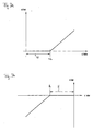
- FIGS. 3a and 3b Signal curves are shown in FIGS. 3a and 3b, which the pressure sensor 26 can deliver via the data line 28 to the control device 30 in determining a mechanical clearance of the drive 32 and the piston 14.
- the relative pressure of the gas 24 is plotted against the relative position of the drive 32 upon movement of the piston 14 in the direction of the double arrow K.
- the absolute pressure of the gas 24 may be plotted over an absolute position of the actuator 32.
- the relative pressure may be related to the ambient pressure associated with another sensor is detected.
- the relative position may be related to any position of the piston, such as an upper or lower dead center position.
- each representation of Figures 3a and 3b marks the point of reversal of the direction of travel of the piston.
- the piston is moved over the distance U to the opening 22 of the pipette tip 18 until, at the relative position U 0, an increase in the relative pressure of the gas 24 of the vessel immersed in a liquid or otherwise closed can be detected.
- a movement of the drive 32 causes a movement of the piston 14 and thus a pressure increase of the gas 24 from the time when the drive has overcome the Stecke U upon movement in the ejection direction after the suction movement of the piston.
- FIG. 3b the determination of the clearance during an intake movement, ie when the piston 14 is raised, is shown away from the opening 22 of the pipetting tip 18.
- the drive 32 first has to overcome the play distance H until at a point H 0 the drive movement actually also leads to a piston movement, so that after the play distance H has been exceeded a further actuation of the drive is required a decrease in the pressure of the gas 24 in the submerged or otherwise closed vessel leads.
- the play paths U and H that can be determined individually for each dosing device 10 can be stored in the memory 34 of the control device 30.
- the accuracy of the drive control can be further increased by the fact that movement games are determined depending on other variables and stored in memory 34 retrievable. For example, the movement games depending on the direction and / or piston position dependent and / or temperature-dependent and / or pressure-dependent, etc. may be stored in the memory 34.
Abstract
Description
Die vorliegende Anmeldung betrifft eine Flüssigkeitsdosiervorrichtung, insbesondere Pipettiervorrichtung zum Aspirieren und Dispensieren von Flüssigkeiten, wobei die Vorrichtung umfasst:
- ein zumindest teilweise mit einem Gas gefülltes Gefäß, welches eine Öffnung aufweist, durch die hindurch Flüssigkeit in das Gefäß aufgenommen oder aus diesem abgegeben wird, wobei die Menge des Gases bei aufgenommener Flüssigkeit durch Gefäßwände und die Flüssigkeit selbst eingeschlossen ist,
- eine Gasdruckveränderungsvorrichtung zur Veränderung des Gasdrucks in dem Gefäß,
- eine Zustandsgrößen-Erfassungsvorrichtung zur Erfassung wenigstens einer Zustandsgröße des Gases in dem Gefäß, sowie
- eine Steuervorrichtung, welche die Gasdruckveränderungsvorrichtung in Abhängigkeit von der von der Zustandsgrößen-Erfassungsvorrichtung erfassten Zustandsgröße ansteuert.
- a vessel at least partially filled with a gas having an opening through which liquid is taken into or discharged from the vessel, the amount of gas being absorbed by vessel walls and the liquid itself when liquid is received,
- a gas pressure changing device for changing the gas pressure in the vessel,
- a state quantity detecting device for detecting at least one state quantity of the gas in the vessel, as well as
- a control device that drives the gas pressure changing device in response to the state quantity detected by the state quantity detecting device.
Weiterhin betrifft die vorliegende Erfindung ein Verfahren zur Vermeidung von Tropfenverlusten bei Flüssigkeitsdosiervorrichtungen.Furthermore, the present invention relates to a method for preventing drop losses in Flüssigkeitsdosiervorrichtungen.
Eine Vorrichtung der eingangs genannten Art ist aus der DE 44 21 303 A1 bekannt. Dort ist eine Pipettiervorrichtung offenbart, welche eine Flüssigkeitsmenge in einen Abschnitt einer Pipettierspitze einsaugt oder aus diesem auslässt. Dies geschieht durch Veränderung des Gasdrucks eines zwischen einem Kolben, Zylinderwänden und der Flüssigkeit eingeschlossenen Gases.A device of the type mentioned is known from DE 44 21 303 A1. There, a pipetting device is disclosed which sucks in or expels an amount of liquid into a portion of a pipetting tip. This is done by changing the gas pressure of a gas trapped between a piston, cylinder walls and the liquid.
Um die Flüssigkeitsmenge möglichst genau aufnehmen zu können, werden der Druck des eingeschlossenen Gases und der herrschende Umgebungsdruck gemessen. Aus den gemessenen Werten wird unter Berücksichtigung der geometrischen Gestalt des Zylinders und der Pipettierspitze ein Korrekturwert errechnet, um möglichst genau die von dem Kolben zurückzulegende Strecke als Sollwert für die Steuerung der Koblenbewegung zu erhalten. Die Steuerung veranlasst daraufhin eine Bewegung des Kolbens auf Grundlage des korrigierten Sollwerts.In order to record the amount of liquid as accurately as possible, the pressure of the trapped gas and the prevailing ambient pressure are measured. From the measured values is under Taking into account the geometric shape of the cylinder and the pipette tip calculates a correction value in order to obtain as accurately as possible the distance to be traveled by the piston as a setpoint for the control of the Koblenbewegung. The controller then initiates movement of the piston based on the corrected setpoint.
Weiterhin kann nach Maßgabe der Offenbarung der DE 44 21 303 A1 daran gedacht sein, den Druck des Gases zwischen Kolben und Flüssigkeitsmenge auch zwischen der Beendigung der Flüssigkeitsaufnahme und dem Beginn der Flüssigkeitsabgabe zu überwachen, um Undichtigkeiten an der Pipette oder dergleichen festzustellen.Furthermore, according to the disclosure of DE 44 21 303 A1 be thought to monitor the pressure of the gas between the piston and the amount of liquid between the termination of the fluid intake and the beginning of the liquid delivery to determine leaks on the pipette or the like.
Weiterhin ist aus der WO 97/02893 A1 ein Verfahren und eine Vorrichtung zur Korrektur eines temperaturabhängigen Fehlers bei der Dosierung einer Flüssigkeit aus einer Pipette bekannt. Die bekannte Vorrichtung umfasst zwei in Reihe miteinander durch einen Gasdurchgang verbundene Kammern, nämlich eine erste Kammer in der Pipettierspitze und eine zweite Kammer in dem Kolben-Zylinder-System mit welchem die Pipettierspitze verbunden ist. Die mit einer Öffnung versehene Pipettierspitze wird zur Aufnahme von Flüssigkeit in diese eingetaucht. Eine Gefäßwand der zweiten Kammer ist durch einen beweglichen Kolben gebildet. Die zweite Kammer ist vollständig, die erste Kammer wenigstens zum Teil mit einem Gas gefüllt. Die Gasmenge ist zwischen Kolben und Flüssigkeit in den beiden Kammern eingeschlossen.Furthermore, WO 97/02893 A1 discloses a method and a device for correcting a temperature-dependent error during the metering of a liquid from a pipette. The known device comprises two chambers connected in series to one another by a gas passage, namely a first chamber in the pipetting tip and a second chamber in the piston-cylinder system to which the pipetting tip is connected. The pipetting tip, which is provided with an opening, is immersed in it to absorb liquid. A vessel wall of the second chamber is formed by a movable piston. The second chamber is complete, the first chamber at least partially filled with a gas. The amount of gas is trapped between the piston and liquid in the two chambers.
Zur Korrektur eines temperaturbedingten Fehlers im Volumen der angesaugten Flüssigkeit schlägt die WO 97/02893 A1 vor, die Temperaturänderung des bei Aufnahme der Flüssigkeit aufgrund der Kolbenbewegung von der ersten zur zweiten Kammer strömenden Gases zu messen und die durch die Kolbenbewegung in der zweiten Kammer bewirkte Volumenänderung auf Grundlage der gemessenen Temperaturänderung während des Flüssigkeitsaufnahmevorgangs zu korrigieren. Hierzu ist wenigstens ein Temperatursensor vorgesehen. Das aus der WO 97/02893 A1 bekannte Verfahren dient lediglich zur Korrektur der Kolbenbewegung während der Flüssigkeitsaufnahme.To correct a temperature-induced error in the volume of liquid sucked, WO 97/02893 A1 proposes to measure the change in temperature of the gas flowing from the first to the second chamber when the liquid is taken up by the piston movement and the change in volume caused by the piston movement in the second chamber to correct based on the measured temperature change during the liquid acquisition process. This is provided at least one temperature sensor. The method known from WO 97/02893 A1 merely serves to correct the piston movement during fluid intake.
Als weiterer Stand der Technik sei auf die EP 0 747 689 B1 verwiesen. Diese zeigt eine Vorrichtung und ein Verfahren zur Entnahme einer Flüssigkeit aus einem dicht geschlossenen Behälter. Neben der Flüssigkeit enthält der dicht geschlossene Behälter eine Gasmenge. Bei der Entnahme von Flüssigkeit aus dem Behälter wird von einem Drucksensor der Gasdruck im Inneren des Behälters überwacht. Davor wird der Gasdruck im Inneren des abgedichteten Gefäßes durch Durchstechen der Dichtung mit einer hohlen Nadel auf Umgebungsdruck gebracht.As a further prior art reference is made to EP 0 747 689 B1. This shows an apparatus and a method for withdrawing a liquid from a tightly closed container. In addition to the liquid, the tightly closed container contains a quantity of gas. When withdrawing liquid from the container, the gas pressure inside the container is monitored by a pressure sensor. Before that, the gas pressure inside the sealed vessel is brought to ambient pressure by piercing the seal with a hollow needle.
Der vorliegenden Anmeldung liegt das folgende Problem zugrunde:The present application is based on the following problem:
Bei Gefäßen, bei welchen eine Flüssigkeitsmenge durch Veränderung des Drucks eines von Gefäßwänden und der Flüssigkeit eingeschlossenen Gases abgegeben oder aufgenommen wird, wird die Flüssigkeit zwischen einem Flüssigkeitsaufnahmevorgang und einem Flüssigkeitsabgabevorgang zum Teil über beträchtliche Zeit in dem Gefäß gehalten, etwa um Transportstrecken zu überwinden. Während dieser Zeit halten der Druckunterschied zwischen dem Umgebungsdruck und dem Druck der eingeschlossenen Gasmenge sowie zwischen Flüssigkeit und benetzter Wand wirkende Reibungs- und Haftkräfte die Flüssigkeit in dem Gefäß. Dabei hat der Druckunterschied zwischen dem Umgebungsdruck und dem Gasdruck im Inneren des Gefäßes den größten Anteil an der die Flüssigkeit im Gefäß haltenden Kraft.In vessels in which an amount of liquid is delivered or received by varying the pressure of a gas trapped by vessel walls and the liquid, the liquid is kept in the vessel for a considerable time between a liquid receiving operation and a liquid discharging operation, such as to overcome transport routes. During this time, the pressure difference between the ambient pressure and the pressure of the trapped gas as well as frictional and adhesive forces acting between the liquid and the wetted wall maintain the liquid in the vessel. In this case, the pressure difference between the ambient pressure and the gas pressure in the interior of the vessel has the largest share of the force holding the liquid in the vessel.
Während die Flüssigkeit in dem Gefäß gehalten wird, kann sich der Druck des im Gefäß eingeschlossenen Gases aufgrund von Verdunstung oder aufgrund von Temperaturausgleichsvorgängen verändern.As the liquid is held in the vessel, the pressure of the gas trapped in the vessel may change due to evaporation or due to temperature compensation processes.
Verdunstet beispielsweise aufgenommene Flüssigkeit, so steigt der Gasdruck im Gefäß an. Dabei steigt der Gasdruck in der Regel stärker als die Gewichtskraft der noch nicht verdampften Flüssigkeit abnimmt.Evaporates, for example, absorbed liquid, so the increases Gas pressure in the vessel. The gas pressure usually increases more than the weight of the not yet evaporated liquid decreases.
Wird eine warme Flüssigkeit in dem Gefäß aufgenommen, so kühlt sich diese unter Abgabe an Wärme an das in dem Gefäß eingeschlossene Gas ab. Diese Erwärmung des Gases führt wiederum zu einem Anstieg des Drucks des eingeschlossenen Gases.When a warm liquid is taken up in the vessel, it cools, giving off heat to the gas trapped in the vessel. This heating of the gas in turn leads to an increase in the pressure of the enclosed gas.
Die geschilderten Vorgänge können dazu führen, dass durch den unerwünscht erhöhten Gasdruck ein Teil der aufgenommenen Flüssigkeitsmenge unerwünschterweise aus dem Gefäß ausgeschoben wird. Die ausgeschobene Flüssigkeit tropft dann vom Gefäß ab. Im Ergebnis können dadurch trotz zunächst korrekt aufgenommener Flüssigkeitsmengen unerwünschterweise fehlerhafte Flüssigkeitsmengen abgegeben werden.The described processes can lead to the unwanted increased gas pressure, a part of the liquid absorbed amount is undesirably ejected from the vessel. The ejected liquid then drips off the vessel. As a result, undesirably erroneous amounts of liquid can be dispensed despite first correctly taken in liquid quantities.
Es ist daher Aufgabe der vorliegenden Erfindung, eine technische Lehre bereitzustellen, mit welcher eine in ein Gefäß dosierte Flüssigkeit ohne Tropfenverlust über lange Zeit in dem Gefäß gehalten werden kann. Dadurch können beispielsweise weite Transportstrecken zurückgelegt oder die Flüssigkeitsdosierungsvorrichtung ohne Verlust von dosierter Flüssigkeit nach der Aufnahme der Flüssigkeit für wichtige kurzfristig erforderliche Eingriffe angehalten werden.It is therefore an object of the present invention to provide a technical teaching with which a metered into a vessel liquid can be kept without drop loss for a long time in the vessel. As a result, for example, long transport distances can be covered or the liquid metering device can be stopped without loss of metered liquid after receiving the liquid for important short-term required interventions.
Diese Aufgabe wird gemäß einem ersten Gesichtspunkt durch eine gattungsgemäße Flüssigkeitsdosiervorrichtung gelöst, bei welcher die Steuervorrichtung eine Regelvorrichtung ist, welche dazu ausgebildet ist, zumindest während eines Regelzeitabschnitts zwischen Flüssigkeitsaufnahme und Flüssigkeitsabgabe die Gasdruckveränderungsvorrichtung in Abhängigkeit von der erfassten Zustandsgröße derart anzusteuern, dass der tatsächliche Gasdruck im Gefäß während des Regelzeitabschnitts im Wesentlichen bei einem vorbestimmten Soll-Gasdruck gehalten wird.This object is achieved according to a first aspect by a generic Flüssigkeitsdosiervorrichtung, wherein the control device is a control device which is adapted to control at least during a control period between liquid intake and liquid delivery, the gas pressure changing device in response to the detected state variable such that the actual gas pressure in Vessel is held during the control period substantially at a predetermined target gas pressure.
Mit "im Wesentlichen" sollen in dieser Anmeldung geringfügige Abweichungen erfasst sein, etwa toleranzbedingte Abweichungen oder auf das jeweils verwendete Regelverfahren (z.B. 2-Punkt-Regelung) zurückzuführende Abweichungen.By "substantially" in this application minor Deviations may be recorded, such as deviations due to tolerances or deviations attributable to the control method used (eg 2-point control).
Es reicht aus, den Gasdruck im Gefäß nur über einen Zeitabschnitt und nicht über die gesamte Zeit zwischen Flüssigkeitsaufnahme und Flüssigkeitsabgabe auf einen vorbestimmten Soll-Gasdruck zu regeln, da Verdunstungs- oder Temperaturausgleichsprozesse langsam ablaufen. Darüber hinaus stellt sich bei beiden Prozessen mit der Zeit ein Gleichgewichtszustand ein, so dass die Änderung des ungeregelten Gasdrucks durch Verdunstung oder Temperaturveränderung über die Zeit nicht mit konstanter, sondern mit abnehmender Geschwindigkeit erfolgt.It is sufficient to regulate the gas pressure in the vessel only over a period of time and not over the entire time between liquid intake and liquid delivery to a predetermined target gas pressure, since evaporation or temperature compensation processes proceed slowly. Moreover, in both processes an equilibrium state arises over time, so that the change in the unregulated gas pressure due to evaporation or temperature change over time does not take place with a constant, but with decreasing speed.
Vorzugsweise wird der Gasdruck in einem Regelzeitabschnitt bei einem vorbestimmten Soll-Gasdruck gehalten, welcher Regelzeitabschnitt einen Zeitbereich in der ersten Hälfte, vorzugsweise im ersten Viertel, der zwischen dem Endzeitpunkt des Flüssigkeitsaufnahmevorgans und dem Beginnzeitpunkt des Flüssigkeitsabgabevorgangs liegenden Zeitspanne umfasst. Hier laufen die Verdunstungs- und Temperaturausgleichsprozesse am schnellsten ab und bewirken eine schnellere Änderung des Gasdrucks, verglichen mit einem später liegenden Zeitabschnitt zwischen Flüssigkeitsaufnahme und Flüssigkeitsabgabe. Es ist daher zur sicheren Verhinderung eines Abtropfens weiter vorteilhaft, wenn der Regelzeitabschnitt das erste Viertel oder besonders vorteilhaft die erste Hälfte der zwischen dem Endzeitpunkt des Flüssigkeitsaufnahmevorgangs und dem Beginnzeitpunkt des Flüssigkeitsabgabevorgangs liegenden Zeitspanne umfasst.Preferably, the gas pressure is maintained at a predetermined target gas pressure in a control period, which control period comprises a time period in the first half, preferably in the first quarter, between the end time of the liquid receiving device and the start time of the liquid dispensing operation. Here, the evaporation and temperature compensation processes are fastest and cause a faster change in gas pressure compared to a later period between fluid intake and fluid delivery. It is therefore further advantageous for the reliable prevention of dripping when the control period comprises the first quarter or particularly advantageously the first half of the period lying between the end time of the liquid receiving operation and the start time of the liquid dispensing operation.
Bei besonders sensiblen Flüssigkeiten kann größtmögliche Sicherheit während der Haltephase zwischen Flüssigkeitsaufnahmevorgang und Flüssigkeitsabgabevorgang erreicht werden, wenn der Regelzeitabschnitt die gesamte zwischen dem Endzeitpunkt des Flüssigkeitsaufnahmevorgangs und dem Beginnzeitpunkt des Flüssigkeitsabgabevorgangs liegende Zeitspanne umfasst.In the case of particularly sensitive fluids, the greatest possible safety can be achieved during the holding phase between the liquid intake and the liquid discharge process if the control period covers the entire time between the end time of the liquid intake operation and the start time of the liquid discharge operation Period covers.
Da unterstellt werden soll, dass die korrekte Menge an Flüssigkeit aufgenommen wurde, kann ein Tropfenverlust von Flüssigkeit während der Haltephase zwischen Flüssigkeitsaufnahmevorgang und Flüssigkeitsabgabevorgang in einfacher Weise vermieden werden, wenn der vorbestimmte Soll-Gasdruck kleiner oder gleich einem zu dem oder nahe bei dem Endzeitpunkt des Flüssigkeitsaufnahmevorgangs im Gefäß herrschenden Gasdruck ist.By assuming that the correct amount of liquid has been taken in, dropping of liquid during the holding phase between the liquid receiving operation and the liquid discharging operation can be easily avoided if the predetermined target gas pressure is less than or equal to or near the end time of the Fluid receiving process prevailing in the vessel gas pressure.
Allerdings kann es vorteilhaft sein, durch die Flüssigkeitsbewegung bedingte dynamische Effekte am Gas erst abklingen zu lassen und einen späteren, nach dem Endzeitpunkt des Flüssigkeitsaufnahmevorgangs erfassten Gasdruck als Soll-Gasdruck zu verwenden. Wie zeitlich nahe der als Soll-Gasdruck verwendete im Gefäß herrschende Gasdruck am Endzeitpunkt des Flüssigkeitsaufnahmevorgangs vorzugsweise liegen kann, hängt von den bei dem jeweiligen Dosiervorgang vorliegenden Parametern ab, etwa von einem Sättigungsgrad des Gases oder von einem Temperaturunterschied zwischen Gas und Flüssigkeit. Man kann jedoch davon ausgehen, dass bei den meisten Dosiervorgängen jeder Gasdruck als Soll-Gasdruck dienen kann, welcher in den ersten 10 Sekunden ab dem Endzeitpunkt des Flüssigkeitsaufnahmevorgangs im Gefäß vorliegt.However, it may be advantageous to allow dynamic effects on the gas caused by the fluid movement to subside first and to use a later gas pressure detected after the end time of the fluid intake event as the desired gas pressure. How close in time to the gas pressure prevailing in the vessel at the end time of the liquid intake process, which is used as the target gas pressure, preferably depends on the parameters present in the respective metering process, for example a degree of saturation of the gas or a temperature difference between gas and liquid. However, it can be assumed that for most metering operations, each gas pressure can serve as the target gas pressure which is present in the vessel in the first 10 seconds from the end time of the liquid intake process.
Grundsätzlich kann daran gedacht sein, beliebige Zustandsgrößen des Gases zu erfassen, etwa Temperatur, Gasvolumen oder Gasdruck. Durch entsprechende Gleichungen, wie der idealen Gasgleichung oder entsprechenden Gleichungen zur Beschreibung von adiabaten oder polytropen Zustandsänderungen und dergleichen, können die erfassten Zustandsgrößen mit dem im Gefäß herrschenden Gasdruck in Beziehung gesetzt werden. Da, wie oben bereits gesagt, der Druckunterschied zwischen dem Umgebungsdruck und dem Druck des im Gefäß eingeschlossenen Gases den Hauptanteil am Verbleiben der Flüssigkeit im Gefäß trägt, ist es besonders vorteilhaft, durch eine Drucksensoranordnung den Gasdruck im Gefäß zu erfassen. Dies liefert die höchste Regelungsgenauigkeit. Unter Drucksensoranordnung wird im Sinne der vorliegenden Anmeldung eine Einrichtung zur Messung des Drucks mit wenigstens einem Drucksensor verstanden.Basically, it may be thought to detect any state variables of the gas, such as temperature, gas volume or gas pressure. By appropriate equations, such as the ideal gas equation or corresponding equations for describing adiabatic or polytropic state changes and the like, the detected state variables can be related to the gas pressure prevailing in the vessel. Since, as stated above, the pressure difference between the ambient pressure and the pressure of the gas trapped in the vessel carries the major part in the retention of the liquid in the vessel, it is particularly advantageous, by a pressure sensor arrangement to detect the gas pressure in the vessel. This provides the highest control accuracy. For the purposes of the present application, a pressure sensor arrangement is understood to mean a device for measuring the pressure with at least one pressure sensor.
Das Gefäß kann eine Kolben-Zylinder-Anordnung und eine daran angeordnete Pipettierspitze umfassen, wobei dann aus Kostengründen die Drucksensoranordnung an der Kolben-Zylinder-Anordnung vorgesehen ist. Ansonsten müsste jede Pipettierspitze mit einer Drucksensoranordnung versehen sein und die jeweilige Drucksensoranordnung nach Aufnahme der Pipettierspitze mit der Regeleinrichtung gekoppelt werden. Dies stellt einen erheblichen Aufwand dar.The vessel may comprise a piston-cylinder arrangement and a pipetting tip arranged thereon, the pressure sensor arrangement then being provided on the piston-cylinder arrangement for cost reasons. Otherwise, each pipetting tip would have to be provided with a pressure sensor arrangement, and the respective pressure sensor arrangement should be coupled to the control device after the pipetting tip has been received. This represents a considerable effort.
Es kann theoretisch daran gedacht sein, eine Turbine als Gasdruckveränderungsvorrichtung vorzusehen, welche Gas in das Gefäß einbläst oder aus diesem ausbläst. In den allermeisten Fällen ist jedoch die Gasdruckveränderungvorrichtung eine mechanische Vorrichtung mit einem Antrieb und einem von diesem angetriebenen Bauteil, welches einen Teil der Gefäßwand bildet, so dass eine Bewegung des Bauteils zu einer Erhöhung oder Verringerung des Gasvolumens im Gefäß und damit verbunden zu einem Druckabfall oder Druckanstieg des Gasdrucks im Gefäß führt. Dabei ist einer Veränderungsrichtung des Gasdrucks, d.h. steigend oder fallend, eine Bewegungsrichtung des Bauteils zugeordnet. Häufig ist bei einer Umkehr der Bewegungsrichtung des Bauteils ein Bewegungsspiel zu überwinden.It may theoretically be thought to provide a turbine as a gas pressure varying device which injects gas into or out of the vessel. In the vast majority of cases, however, the gas pressure varying device is a mechanical device having a drive and a driven by the component which forms part of the vessel wall, so that movement of the component to an increase or decrease of the gas volume in the vessel and thus to a pressure drop or Pressure increase of the gas pressure in the vessel leads. In this case, a direction of change of the gas pressure, i. rising or falling, assigned a direction of movement of the component. Frequently, when the direction of movement of the component is reversed, a movement play must be overcome.
Das erwähnte Bewegungsspiel kann wiederum Ursache für Ungenauigkeiten bei der aufgenommenen oder der abgegebenen Flüssigkeitsmenge sein, etwa dann, wenn die abgegebene oder aufgenommene Flüssigkeitsmenge anhand der Bewegung des Antriebs oder erfasster anderer mit dem Antrieb zusammenhängender Größen berechnet wird. Durch das Bewegungsspiel sind nämlich Antriebsaktivitäten vorhanden, die tatsächlich keine Änderung des Gasdrucks und damit keine Änderung der im Gefäß vorhandenen Flüssigkeitsmenge bewirken.Again, the mentioned play of motion can be the cause of inaccuracies in the amount of fluid taken or delivered, such as when the amount of fluid dispensed or received is calculated from the movement of the drive or other sensed quantities related to the drive. Because of the play of motion, namely, there are driving activities that actually do not change the gas pressure and therefore do not change the one present in the vessel Effect amount of liquid.
Die so möglicherweise auftretende Ungenauigkeit der vom Gefäß aufgenommenen oder aus diesem abgegebenen Flüssigkeitsmenge kann in vorteilhafter Weise dadurch reduziert oder gar beseitigt werden, dass die Regelvorrichtung derart zur Ermittlung des Bewegungsspiels ausgebildet ist, dass sie den Antrieb auf eine erste Antriebsrichtung folgend solange in entgegengesetzter zweiter Antriebsrichtung antreibt, bis die Zustandsgrößen-Erfassungsvorrichtung eine Veränderung der wenigstens einen Zustandsgröße erfasst.The thus occurring inaccuracy of the amount of liquid received by the vessel or discharged from this can be advantageously reduced or even eliminated that the control device is designed to determine the movement play that they follow the drive in a first drive direction in the opposite second drive direction drives until the state quantity detection device detects a change in the at least one state variable.
Um eine möglichst genaue Ermittlung des Gasdrucks zu ermöglichen, kann die Regelvorrichtung dazu ausgebildet sein, den Antrieb bei der Ermittlung des Bewegungsspiels schrittweise anzusteuern. Dadurch ist es möglich, dynamische Effekte vor einer Erfassung des Gasdrucks im Inneren des Gefäßes abklingen zu lassen.In order to enable the most accurate determination of the gas pressure, the control device may be designed to control the drive in the determination of the movement play step by step. This makes it possible to decay dynamic effects before detection of the gas pressure inside the vessel.
Der Vorteil einer derart ausgebildeten Flüssigkeitsdosiervorrichtung liegt weiter darin, dass jede Flüssigkeitsdosiervorrichtung individuell ihr systemimmanentes Bewegungsspiel ermitteln kann. Vorzugsweise umfasst die Flüssigkeitsdosiervorrichtung eine Speichervorrichtung, so dass das individuell ermittelte Bewegungsspiel darin abgespeichert und bei Bedarf abgerufen werden kann. Ist die Flüssigkeitsdosiervorrichtung für einen Einsatz unter sich ändernden Umgebungsbedingungen gedacht, können Bewegungsspiele zusammen mit weiteren Größen ermittelt werden, so dass in der Speichervorrichtung ermittelte Bewegungsspiele in Abhängigkeit von weiteren Größen abgespeichert werden. So kann das Bewegungsspiel abhängig von unterschiedlichen Umgebungstemperaturen oder/und Umgebungsdrücken oder/und Betriebsdauern oder/und Bauteilstellungen usw. abgespeichert sein. Es ist weiter vorteilhaft, das jeweilige Bewegungsspiel vor einem wertschöpfenden Einsatz zunächst anhand einer Dosierung von Testflüssigkeiten wie etwa Wasser oder dergleichen zu ermitteln, so dass das Bewegungsspiel dann im tatsächlichen Dosierbetrieb bekannt ist. Hierdurch wird ein Verlust von möglicherweise wertvollen Flüssigkeiten bei der Ermittlung des Bewegungsspiels vermieden.The advantage of a liquid metering device designed in this way is that each liquid metering device can individually determine its system-inherent movement play. Preferably, the Flüssigkeitsdosiervorrichtung comprises a memory device, so that the individually determined movement play can be stored therein and retrieved when needed. If the liquid metering device is intended for use under changing environmental conditions, motion games can be determined together with further variables, so that movement games determined in the storage device are stored as a function of further variables. Thus, the movement play depending on different ambient temperatures and / or ambient pressures and / or operating periods and / or component positions, etc. may be stored. It is also advantageous to first determine the respective movement play before a value-adding insert on the basis of a dosage of test liquids such as water or the like, so that the movement play then takes place in the actual metering operation is known. As a result, a loss of potentially valuable fluids in the determination of the movement play is avoided.
Das zuvor erwähnte, vom Antrieb bewegbare Bauteil kann ein einen Gefäßwandabschnitt bildender beweglicher Kolben sein. Es kann jedoch auch eine Wand eines mit dem Gefäß verbundenen Balgs sein.The aforementioned drive-movable component may be a movable piston forming a vessel wall section. However, it may also be a wall of a bellows connected to the vessel.
Gemäß einem weiteren Gesichtspunkt wird die oben genannte Aufgabe auch gelöst durch ein Verfahren zur Vermeidung von Tropfenverlusten bei Flüssigkeitsdosiervorrichtungen, insbesondere Pipettiervorrichtungen, welches die folgenden Schritte aufweist, welche zumindest in einem Zeitabschnitt der zwischen Flüssigkeitsaufnahmevorgang und Flüssigkeitsabgabevorgang liegenden Zeitspanne ausgeführt werden:
- Erfassen wenigstens einer Zustandsgröße eines Gases, welches in einem eine Flüssigkeit aufnehmenden Gefäß der Flüssigkeitsdosiervorrichtung zwischen Gefäßwänden und der Flüssigkeit im Wesentlichen eingeschlossen ist, sowie
- Regeln des Drucks des Gases in Abhängigkeit von der erfassten Zustandsgröße derart, dass der tatsächliche Gasdruck mit einem vorbestimmten Soll-Gasdruck im Wesentlichen übereinstimmt.
- Detecting at least one state variable of a gas substantially trapped in a liquid receiving vessel of the liquid metering device between vessel walls and the liquid, and
- Controlling the pressure of the gas in response to the detected state variable such that the actual gas pressure substantially coincides with a predetermined desired gas pressure.
Da das Verfahren in engem Zusammenhang mit der zuvor beschriebenen Vorrichtung steht, wird zur ergänzenden Erläuterung des Verfahrens und der damit erzielbaren Vorteile auf die obige Beschreibung der erfindungsgemäßen Flüssigkeitsdosiervorrichtung verwiesen.Since the method is closely related to the device described above, reference is made to the supplementary explanation of the method and the advantages that can be achieved with reference to the above description of the inventive liquid metering device.
Zwar kann der Regelungsschritt zur Regelung des Gasdrucks bei im Vorhinein bekanntem Soll-Gasdruck bereits vor Ende des Flüssigkeitsaufnahmevorgangs beginnen. Es ist jedoch zur Vermeidung von Tropfenverlusten zwischen Flüssigkeitsaufnahme und Flüssigkeitsabgabe wichtig, dass der Erfassungsschritt und der Regelungsschritt zwischen dem Endzeitpunkt des Flüssigkeitsabgabevorgangs und dem Beginnzeitpunkt des Flüssigkeitsabgabevorgangs erfolgen. Aus den oben geschilderten Gründen kann der Gasdruck vorteilhaftweise in einem Zeitabschnitt geregelt werden, welcher einen Zeitbereich in der ersten Hälfte, vorzugsweise im ersten Viertel der zwischen dem Endzeitpunkt des Flüssigkeitsaufnahmevorgangs und dem Beginnzeitpunkt des Flüssigkeitsabgabevorgangs liegenden Zeitspanne umfasst. Größtmögliche Sicherheit erhält man dann, wenn der Erfassungschritt und der Regelungsschritt während der gesamten zwischen den genannten Zeitpunkten liegenden Zeitspanne ausgeführt werden.Although the control step to control the gas pressure at a pre-known target gas pressure already begin before the end of the fluid intake operation. However, in order to prevent drop losses between liquid intake and liquid delivery, it is important that the detection step and the control step be between the end time of the liquid discharge operation and the start timing of the liquid discharge operation. From the above The gas pressure can advantageously be regulated in a time period which comprises a time range in the first half, preferably in the first quarter of the period lying between the end time of the fluid intake operation and the start time of the fluid delivery operation. The greatest possible security is obtained when the detection step and the control step are carried out during the entire period of time between said points in time.
Handelt es sich bei der Flüssigkeitsdosiervorrichtung um die zuvor beschriebene Bauart, bei welcher ein einen Gefäßwandabschnitt bildendes Bauteil von einem Antrieb zur Bewegung antreibbar ist und eine Bauteilbewegung eine Veränderung des Gasdrucks bewirkt, so umfasst der Regelungsschritt in einer konkreten Ausgestaltung vorteilhafterweise ein Ansteuern des Antriebs in Abhängigkeit von der erfassten Zustandsgröße.If the liquid metering device is the previously described type in which a component forming a vessel wall section can be driven by a drive for movement and a component movement causes a change in the gas pressure, then the control step in a specific embodiment advantageously comprises activating the drive in dependence from the detected state variable.
Ein oben beschriebenes Bewegungsspiel kann mit Hilfe des erfindungsgemäßen Verfahrens dadurch ermittelt werden, dass auf eine erste Antriebsrichtung folgend der Antrieb in entgegengesetzter zweiter Antriebsrichtung solange angesteuert wird, bis die Zustandsgrößen-Erfassungsvorrichtung eine Veränderung der wenigstens einen Zustandsgröße erfasst. Zur Vermeidung möglicherweise störender dynamischer Effekte bei der Erfassung der wenigstens einen Zustandsgröße kann das Ansteuern des Antriebs in der zweiten Antriebsrichtung schrittweise erfolgen, wobei jedem Ansteuerschritt eine Erfassung der wenigstens einen Zustandsgröße zugeordnet ist, vorzugsweise die Erfassung der wenigstens einen Zustandsgröße nach der Ansteuerung des Antriebs erfolgt.A movement described above can be determined with the aid of the method according to the invention by following the drive in the opposite second drive direction following a first drive direction until the state variable detection device detects a change in the at least one state variable. In order to avoid possibly disturbing dynamic effects in the detection of the at least one state variable, the driving of the drive in the second drive direction can take place step by step, wherein each activation step is associated with a detection of the at least one state variable, preferably the detection of the at least one state variable after the activation of the drive ,
Eine möglichst hohe Genauigkeit bei der Bestimmung des Bewegungsspiels kann dadurch erzielt werden, dass während der Ermittlung des Bewegungsspiels weitere Größen erfasst werden, wie etwa die Stellung des Bauteils relativ zum Gefäß oder/und eine Temperatur, insbesondere Umgebungstemperatur oder/und des Umgebungsdrucks.The highest possible accuracy in the determination of the movement play can be achieved by detecting further variables during the determination of the movement play, such as the position of the component relative to the vessel or / and a temperature, in particular Ambient temperature or / and the ambient pressure.
Vorteilhafterweise werden das wenigstens eine ermittelte Bewegungsspiel gespeichert, ggf. gemeinsam mit den zuvor genannten weiteren dem jeweils zu speichernden Bewegungsspiel zugeordneten Größen. Im Bedarfsfall kann dann das Bewegungsspiel, ggf. abhängig von aktuell vorliegenden Betriebsparametern, aus dem Speicher abgerufen und bei der Ansteuerung des Antriebs berücksichtigt werden.Advantageously, the at least one determined movement play is stored, possibly together with the previously mentioned further variables assigned to the respective movement play to be stored. If necessary, then the movement play, possibly depending on currently available operating parameters, retrieved from the memory and taken into account in the control of the drive.
Aus oben genannten Gründen ist für eine Regelung des Gasdrucks dessen unmittelbare Erfassung ohne Umwege über andere Zustandsgrößen von besonderem Vorteil.For reasons mentioned above, for a regulation of the gas pressure, its direct detection without detours over other state variables is of particular advantage.
Darüber hinaus soll nicht ausgeschlossen sein, dass zur redundanten Erfassung des Gasdrucks weitere Zustandsgrößen, wie etwa die Temperatur oder das Gasvolumen erfasst werden und die Flüssigkeitsdosiervorrichtung mit entsprechenden Sensoren versehen ist. Dies ermöglicht eine wechselseitige Überprüfung der Funktionstüchtigkeit der verwendeten Sensoren, insbesondere der Drucksensoranordnung.In addition, it should not be ruled out that, for redundant detection of the gas pressure, further state variables, such as the temperature or the gas volume, are detected and the liquid metering device is provided with corresponding sensors. This allows a mutual check of the functionality of the sensors used, in particular the pressure sensor arrangement.
Die vorliegende Erfindung wird im folgenden anhand der beiliegenden Zeichnungen näher erläutert werden. Es stellt dar:
- Figur 1
- eine schematische Darstellung einer erfindungsgemäßen Flüssigkeitsdosiervorrichtung,
- Figuren 2a und b
- einen schematischen Ablauf einer Regelung des im Gefäß herrschenden Gasdrucks gemäß der vorliegenden Erfindung, sowie
- Figuren 3a und b
- Graphen welche den relativen Druck eines in einem Gefäß eingeschlossenen Gases abhängig von der relativen Position eines den Gasdruck beeinflussenden bewegbaren Bauteils bei der Bestimmung eines Bewegungsspiels zeigen.
- FIG. 1
- a schematic representation of a Flüssigkeitsdosiervorrichtung invention,
- FIGS. 2a and b
- a schematic sequence of a control of the pressure prevailing in the vessel gas pressure according to the present invention, and
- FIGS. 3a and b
- Graphs showing the relative pressure of a gas enclosed in a vessel depending on the relative position of a gas pressure affecting movable component in the determination of a movement play show.
In Figur 1 ist eine erfindungsgemäße Flüssigkeitsdosiervorrichtung allgemein mit 10 bezeichnet. Die Flüssigkeitsdosiervorrichtung 10 umfasst ein Kolben-Zylinder-System 12 mit einem Kolben 14, welcher in einem Zylinder 16 in Richtung des Doppelpfeils K beweglich geführt ist.In FIG. 1, a liquid metering device according to the invention is designated generally by 10. The
Am Zylinder 16 ist eine auswechselbare Pipettierspitze 18 aufgenommen, in welcher eine Flüssigkeit 20 vorhanden ist. Die Pipettierspitze 18 bildet zusammen mit dem Zylinder 16 und dem Kolben 14 ein die Flüssigkeit 20 aufnehmendes Gefäß.On the cylinder 16 a
An dem zylinderfernen Längsende 18a weist die Pipettierspitze 18 eine Öffnung 22 auf, durch welche hindurch die Flüssigkeit 20 in die Pipettierspitze 20 aufgenommen wurde und aus dieser wieder abgegeben werden kann.At the cylinder-distal
Der Kolben 14 liegt im Wesentlichen gasdicht an der Innenwand 16a des Zylinders 16 an. Die zur Pipettierspitze 18 hinweisende Kolbenfläche 14a bildet eine Gefäßbegrenzungswand.The
Zwischen der Flüssigkeitsoberfläche 20, der Kolbenfläche 14a, der Zylinderinnenwand 16a und der Innenwand 18b der Pipettierspitze ist ein Gas 24, etwa Luft, eingeschlossen. Statt Luft kann auch ein beliebiges anderes Gas verwendet werden, etwa Stickstoff oder ein Edelgas, falls Reaktionen mit der aufzunehmenden Flüssigkeit 20 auf jeden Fall vermieden werden sollen.Between the
Die Flüssigkeit 20 wurde in an sich bekannter Weise durch Eintauchen der Öffnung 22 in einen Flüssigkeitsvorrat und Bewegen des Kolbens 14 bei eingetauchter Öffnung derart, dass das Volumen des eingeschlossenen Gases 24 vergrößert wird, durch die Öffnung 22 in die Pipettierspitze 18 eingesaugt. Die Pipettierspitze 18 von Figur 1, wie auch von Figur 2a und b, hat die Flüssigkeitsaufnahme bereits abgeschlossen und ist nicht mehr in den Flüssigkeitsvorrat getaucht.The liquid 20 was introduced in a manner known per se by immersing the
Mit dem Innenraum des Gefäßes ist ein Drucksensor 26 zur Erfassung des Gasdrucks des eingeschlossenen Gases 24 in Verbindung. Zwar kann grundsätzlich daran gedacht sein, einen Drucksensor an der Pipettierspitze vorzusehen, jedoch ist es aus Kostengründen vorteilhafter, den Drucksensor 26 an dem im Gegensatz zur Pipettierspitze 18 nicht wechselbaren Zylinder 16 vorzusehen und dauerhaft zu betreiben.Connected to the interior of the vessel is a
Der Drucksensor 26 erfasst den Druck des Gases 24 und liefert ein den Gasdruck repräsentierendes Signal über die Leitung 28 an eine Regeleinrichtung 30, welche dazu ausgebildet ist, einen Antrieb 32 zur Verlagerung des Kolbens 14 in Richtung des Doppelpfeils K in Abhängigkeit eines von dem Drucksensor 26 gelieferten Signals zu betreiben.The
Der Drucksensor 26 kann dabei einen Absolutwert des Drucks des Gases 24 oder kann einen Relativwert, etwa bezogen auf den Umgebungsdruck, an die Regeleinrichtung 30 liefern. Der vom Drucksensor 26 erfasste und an die Regeleinrichtung 30 gelieferte Druckwert ist durch einen Zeiger 34 angedeutet.The
In Figur 2a ist angedeutet, wie Flüssigkeitsteilchen V von der Oberfläche 20a aus in den vom Gas 24 eingenommenen Raum verdunsten. Darüber hinaus gibt die Flüssigkeit 20 Wärme W an das Gas 24 ab. Dadurch steigt der Druck des Gases 24 in dem Gefäß aus Zylinder 16, Kolben 14 und Pipettierspitze 18. Diese Druckerhöhung wird durch den Drucksensor 26 erfasst, wie durch die gegenüber Figur 1 veränderte Stellung des Zeigers 34 angedeutet ist. Ohne Regeleingriff würde diese Druckerhöhung zu einem Ausschieben von Flüssigkeit 20 aus der Öffnung 22 führen.FIG. 2 a indicates how liquid particles V evaporate from the
Die Regeleinrichtung 30 bewegt abhängig von dem vom Drucksensor über die Leitung 28 an sie gelieferten Druckwert den Kolben in Richtung des Pfeils 36 in Figur 2b und vergrößert das Volumen des Gases 24 in dem Gefäß aus den Elementen 14, 16, 18 bis ein vorbestimmter, weiter unten erläuterter, Soll-Gasdruck erreicht ist. Dadurch wird die Druckerhöhung aufgrund von Verdunstung und Wärmeübergang reduziert. Der Druck des Gases 24 erreicht wieder den Wert, welcher unmittelbar nach der Aufnahme der Flüssigkeit 20 in die Pipettenspitze 18 im Inneren des Gefäßes aus Kolben 14, Zylinder 16 und Pipettierspitze 18 geherrscht hat. Die ursprüngliche Stelle, an der sich die Kolbenwand 14a vor der Korrektur befand, ist mit 14a' angegeben.The
Als Soll-Gasdruck wird idealerweise der zum Zeitpunkt des Endes des Flüssigkeitaufnahmevorgangs im Gefäß herrschende Druck verwendet. Da die Druckerhöhung durch Verdunstung oder/und Wärmeübertragung in der Regel nicht blitzartig vor sich geht, kann allgemein ein Gasdruck als Soll-Gasdruck verwendet werden, welcher in einem Zeitraum von 10 Sekunden nach Ende des Flüssigkeitsaufnahmevorgangs im Gefäß herrscht.As desired gas pressure, the pressure prevailing in the vessel at the time of the end of the liquid intake process is ideally used. Since the increase in pressure due to evaporation and / or heat transfer is usually not instantaneous, it is generally possible to use a gas pressure as target gas pressure which prevails in the vessel within a period of 10 seconds after the end of the liquid intake process.
Fachleute werden verstehen, dass entgegen dem geschilderten Beispiel der Kolben auch zur Erhöhung des Drucks des Gases 24 zur Öffnung 22 hin verlagert werden kann, etwa nach Aufnahme besonders kalter Flüssigkeiten, welche dem eingeschlossenen Gas 24 Wärme entziehen und dadurch dessen Druck verringern.It will be understood by those skilled in the art that, contrary to the example described, the piston may also be displaced toward the
In den Figuren 3a und 3b sind Signalverläufe dargestellt, wie sie der Drucksensor 26 über die Datenleitung 28 an die Regeleinrichtung 30 bei der Bestimmung eines mechanischen Spiels des Antriebs 32 und des Kolbens 14 liefern kann. Dabei ist der relative Druck des Gases 24 über der relativen Position des Antriebs 32 bei Bewegung des Kolbens 14 in der Richtung des Doppelpfeils K aufgetragen. Es ist leicht einzusehen, dass an Stelle relativer Werte auch der Absolutdruck des Gases 24 über einer Absolutposition des Antriebs 32 aufgetragen sein kann. Der relative Druck kann beispielsweise auf den Umgebungsdruck bezogen sein, welcher mit einem weiteren Sensor erfasst wird. Die relative Position kann auf eine beliebige Stellung des Kolbens, etwa eine obere oder untere Totpunktstellung bezogen sein.Signal curves are shown in FIGS. 3a and 3b, which the
Der Koordinatenursprung einer jeden Darstellung von Figur 3a und 3b markiert den Punkt einer Umkehr der Bewegungsrichtung des Kolbens. In Figur 3a wird der Kolben über die Strecke U zur Öffnung 22 der Pipettenspitze 18 hin bewegt, bis bei der relativen Position U0 ein Anstieg des relativen Drucks des Gases 24 des in eine Flüssigkeit eingetauchten oder sonst wie geschlossenen Gefäßes erfassbar ist. Dies bedeutet, dass eine Bewegung des Antriebs 32 eine Bewegung des Kolbens 14 und somit einen Druckanstieg des Gases 24 ab dem Zeitpunkt bewirkt, wenn der Antrieb nach erfolgter Ansaugbewegung des Kolbens die Stecke U bei Bewegung in Ausstoßrichtung überwunden hat.The origin of each representation of Figures 3a and 3b marks the point of reversal of the direction of travel of the piston. In FIG. 3a, the piston is moved over the distance U to the
In Figur 3b ist die Ermittlung des Spiels bei einer Ansaugbewegung, d.h. bei einem Anheben des Kolbens 14 von der Öffnung 22 der Pipettierspitze 18 weg dargestellt. Dabei muss der Antrieb 32 nach einem Antrieb des Kolbens 14 von der Öffnung 22 weg zunächst die Spielstrecke H überwinden, bis bei einem Punkt H0 die Antriebsbewegung tatsächlich auch zu einer Kolbenbewegung führt, so dass nach Überschreiten der Spielstrecke H eine weitere Betätigung des Antriebs zu einem Absinken des Drucks des Gases 24 im eingetauchten oder sonst wie geschlossenen Gefäß führt.In FIG. 3b, the determination of the clearance during an intake movement, ie when the
Die so individuell für jede Dosiervorrichtung 10 ermittelbaren Spielstrecken U und H können in dem Speicher 34 der Regelvorrichtung 30 hinterlegt werden. Die Genauigkeit der Antriebssteuerung kann noch dadurch erhöht werden, dass Bewegungspiele abhängig von weiteren Größen ermittelt und im Speicher 34 abrufbar hinterlegt werden. Beispielsweise können die Bewegungspiele richtungsabhängig oder/und kolbenstellungsabhängig oder/und temperaturabhängig oder/und druckabhängig usw. im Speicher 34 hinterlegt sein.The play paths U and H that can be determined individually for each
Claims (18)
dadurch gekennzeichnet, dass die Steuervorrichtung (30) eine Regelvorrichtung (30) ist, welche dazu ausgebildet ist, zumindest während eines Regelzeitabschnitts zwischen Flüssigkeitsaufnahme und Flüssigkeitsabgabe die Gasdruckveränderungsvorrichtung (14, 32) in Abhängigkeit von der erfassten Zustandsgröße derart anzusteuern, dass der tatsächliche Gasdruck im Gefäß (14, 16, 18) während des Regelzeitabschnitts im Wesentlichen bei einem vorbestimmten Soll-Gasdruck gehalten wird.Liquid metering device, in particular a pipetting device for aspirating and dispensing liquids (20), the device comprising:
characterized in that the control device (30) is a control device (30) which is designed to control the gas pressure changing device (14, 32) in dependence on the detected state variable at least during a control period between liquid intake and liquid delivery such that the actual gas pressure in the Vessel (14, 16, 18) is maintained during the control period substantially at a predetermined target gas pressure.
dadurch gekennzeichnet, dass der Regelzeitabschnitt einen Zeitbereich in der ersten Hälfte, vorzugsweise im ersten Viertel, der zwischen dem Endzeitpunkt des Flüssigkeitsaufnahmevorgans und dem Beginnzeitpunkt des Flüssigkeitsabgabevorgangs liegenden Zeitspanne umfasst.Liquid metering device according to claim 1,
characterized in that the control period is a Time range in the first half, preferably in the first quarter, which comprises between the end time of the liquid receiving device and the start time of the liquid discharge operation period.
dadurch gekennzeichnet, dass der Regelzeitabschnitt das erste Viertel, vorzugsweise die erste Hälfte der zwischen dem Endzeitpunkt des Flüssigkeitsaufnahmevorgangs und dem Beginnzeitpunkt des Flüssigkeitsabgabevorgangs liegenden Zeitspanne, besonders bevorzugt die gesamte zwischen diesen Zeitpunkten liegende Zeitspanne umfasst.Liquid metering device according to claim 1 or 2,
characterized in that the control period comprises the first quarter, preferably the first half of the period lying between the end time of the liquid receiving operation and the start time of the liquid dispensing operation, particularly preferably the entire period lying between these times.
dadurch gekennzeichnet, dass der vorbestimmte Soll-Gasdruck kleiner oder gleich einem zu dem oder zeitlich nahe dem Endzeitpunkt des Flüssigkeitsaufnahmevorgangs (14, 16, 18) im Gefäß herrschenden Gasdruck ist.Liquid metering device according to one of the preceding claims,
characterized in that the predetermined target gas pressure is less than or equal to a gas pressure prevailing in the vessel at or near the end time of the liquid receiving operation (14, 16, 18).
dadurch gekennzeichnet, dass die Zustandsgrößen-Erfassungsvorrichtung (26) eine Drucksensoranordnung (26) ist.Liquid metering device according to one of the preceding claims,
characterized in that the state quantity detection device (26) is a pressure sensor arrangement (26).
dadurch gekennzeichnet, dass die Regelvorrichtung (30) derart zur Ermittlung des Bewegungsspiels ausgebildet ist, dass sie den Antrieb (32) auf eine erste Antriebsrichtung folgend solange in entgegengesetzter zweiter Antriebsrichtung antreibt, bis die Zustandsgrößen-Erfassungsvorrichtung (26) eine Veränderung der wenigstens einen Zustandsgröße erfasst.A liquid metering device according to any one of the preceding claims, wherein the gas pressure varying device (14, 32) is a mechanical device having a drive (32) and a component (14) driven therefrom which comprises a part (14a) of the vessel wall (14a, 16a, 18b ), such that a change in the gas pressure by movement of the component (14) is achieved, wherein a direction of change of the gas pressure is associated with a direction of movement of the component (14) and wherein at Reversing the direction of movement of the component (14) is a movement game to overcome
characterized in that the control device (30) is designed for determining the movement play that drives the drive (32) in a first drive direction following in the opposite second drive direction until the state variable detection device (26) a change of the at least one state variable detected.
dadurch gekennzeichnet, dass die Regelvorrichtung (30) dazu ausgebildet ist, den Antrieb (32) zur Ermittlung des Bewegungsspiels schrittweise anzusteuern.Liquid metering device according to claim 6,
characterized in that the control device (30) is adapted to drive the drive (32) for determining the movement play step by step.
dadurch gekennzeichnet, dass sie eine Speichervorrichtung (34) umfasst, welche zur Speicherung des ermittelten Bewegungsspiels ausgebildet ist, vorzugsweise gemeinsam mit weiteren dem jeweils ermittelten Bewegungsspiel zugeordneten Größen.Liquid metering device according to claim 6 or 7,
characterized in that it comprises a memory device (34) which is designed to store the determined movement play, preferably together with further variables assigned to the respectively determined movement play.
dadurch gekennzeichnet, dass sie zur Erfassung der Stellung des Bauteils (14) ausgebildet ist, wobei die Speichervorrichtung (34) zur Abspeicherung von Wertemengen aus ermitteltem Bewegungsspiel und einer diesem jeweils zugeordneten Bauteilstellung ausgebildet ist.Liquid metering device according to claim 8,
characterized in that it is designed to detect the position of the component (14), wherein the storage device (34) is designed for storing sets of values from determined movement play and a respectively associated component position.
dadurch gekennzeichnet, dass das Bauteil (14) ein einen Gefäßwandabschnitt (14a) bildender beweglicher Kolben (14) ist oder/und dass das Gefäß (14, 16, 18) eine, vorzugsweise wechselbare, Pipettierspitze (18) umfasst.Liquid metering device according to one of the preceding claims,
characterized in that the component (14) is a movable piston (14) forming a vessel wall section (14a) and / or that the vessel (14, 16, 18) comprises a, preferably changeable, pipette tip (18).
dadurch gekennzeichnet, dass der Erfassungsschritt und der Regelungsschritt während eines Regelungszeitabschnitts erfolgen, welcher einen Zeitbereich in der ersten Hälfte, vorzugsweise in dem ersten Viertel der zwischen dem Endzeitpunkt des Flüssigkeitsaufnahmevorgangs und dem Beginnzeitpunkt des Flüssigkeitsabgabevorgangs liegenden Zeitspanne umfasst, besonders bevorzugt die gesamte zwischen diesen Zeitpunkten liegende Zeitspanne umfasst.Method according to claim 11,
characterized in that the detection step and the control step occur during a control period comprising a time period in the first half, preferably in the first quarter of the period between the end time of the fluid intake and the start time of the fluid delivery, more preferably all between these times Period covers.
dadurch gekennzeichnet, dass der Regelungsschritt ein Ansteuern des Antriebs (32) in Abhängigkeit von der erfassten Zustandsgröße umfasst.The method of claim 11 or 12, wherein the Flüssigkeitsdosiervorrichtung comprises a mechanical device with a drive and driven by this, a vessel wall portion (14a) forming member (14) as means (14, 30, 32) for changing the gas pressure, such that a change the gas pressure is achieved by movement of the component (14),
characterized in that the control step is a driving of the drive (32) in dependence on the detected state variable.
dadurch gekennzeichnet, dass zur Ermittlung des Bewegungsspiels auf eine erste Antriebsrichtung folgend der Antrieb (32) in entgegengesetzter zweiter Antriebsrichtung solange angesteuert wird, bis die Zustandsgrößen-Erfassungsvorrichtung (26) eine Veränderung der wenigstens einen Zustandsgröße erfasst.A method according to claim 13, wherein a direction of change of the gas pressure is associated with a direction of movement of the component (14), and wherein a movement play is to be overcome when the direction of movement of the component (14) is reversed.
characterized in that for determining the movement play in a first drive direction following the drive (32) is driven in the opposite second drive direction until the state variable detection device (26) detects a change in the at least one state variable.
dadurch gekennzeichnet, dass das Ansteuern des Antriebs (32) in der zweiten Antriebsrichtung schrittweise erfolgt, wobei jedem Ansteuerschritt eine Erfassung der wenigstens einen Zustandsgröße zugeordnet ist.Method according to claim 14
characterized in that the driving of the drive (32) takes place stepwise in the second drive direction, wherein each control step is associated with a detection of the at least one state variable.
dadurch gekennzeichnet, dass während der Ermittlung des Bewegungsspiels weitere Größen erfasst werden, wie etwa die Stellung des Bauteils (14) relativ zum Gefäß (14, 16, 18) oder/und eine Temperatur, insbesondere Umgebungstemperatur.Method according to claim 14 or 15,
characterized in that during the determination of the movement play other variables are detected, such as the position of the component (14) relative to the vessel (14, 16, 18) and / or a temperature, in particular ambient temperature.
dadurch gekennzeichnet, dass es einen Schritt einer Speicherung des ermittelten Bewegungsspiels umfasst, gegebenenfalls gemeinsam mit dem Bewegungsspiel zugeordneten weiteren Größen.Method according to one of claims 14 to 16,
characterized in that it comprises a step of storing the determined movement play, possibly together with the movement play associated further sizes.
dadurch gekennzeichnet, dass die erfasste Zustandsgröße der Gasdruck des eingeschlossenen Gases (24) ist.Method according to one of claims 11 to 16,
characterized in that the detected state quantity is the gas pressure of the trapped gas (24).
Priority Applications (4)
| Application Number | Priority Date | Filing Date | Title |
|---|---|---|---|
| EP04015682A EP1614468B1 (en) | 2004-07-02 | 2004-07-02 | Drip-less pipetting device and the mode of operation |
| ES04015682T ES2274349T3 (en) | 2004-07-02 | 2004-07-02 | PIPETED DEVICE INSURANCE AGAINST DRIPPING AND PROCEDURE FOR PIPETED INSURANCE AGAINST DRIPPING. |
| DE502004002377T DE502004002377D1 (en) | 2004-07-02 | 2004-07-02 | Drip-proof pipetting device and drip-proof pipetting method |
| AT04015682T ATE348659T1 (en) | 2004-07-02 | 2004-07-02 | DRIP-PROOF METERING DEVICE AND DRIP-PROOF METHOD |
Applications Claiming Priority (1)
| Application Number | Priority Date | Filing Date | Title |
|---|---|---|---|
| EP04015682A EP1614468B1 (en) | 2004-07-02 | 2004-07-02 | Drip-less pipetting device and the mode of operation |
Publications (2)
| Publication Number | Publication Date |
|---|---|
| EP1614468A1 true EP1614468A1 (en) | 2006-01-11 |
| EP1614468B1 EP1614468B1 (en) | 2006-12-20 |
Family
ID=34925603
Family Applications (1)
| Application Number | Title | Priority Date | Filing Date |
|---|---|---|---|
| EP04015682A Active EP1614468B1 (en) | 2004-07-02 | 2004-07-02 | Drip-less pipetting device and the mode of operation |
Country Status (4)
| Country | Link |
|---|---|
| EP (1) | EP1614468B1 (en) |
| AT (1) | ATE348659T1 (en) |
| DE (1) | DE502004002377D1 (en) |
| ES (1) | ES2274349T3 (en) |
Cited By (9)
| Publication number | Priority date | Publication date | Assignee | Title |
|---|---|---|---|---|
| EP2006022A1 (en) | 2007-06-15 | 2008-12-24 | Hamilton Bonaduz AG | Sample processing arrangement for a liquid metering device |
| WO2010060448A1 (en) * | 2008-11-28 | 2010-06-03 | Hamilton Bonaduz Ag | Metering device suited for metering very small metering volumes and metering method |
| WO2011107472A1 (en) | 2010-03-01 | 2011-09-09 | Novozymes A/S | Viscosity pressure assay |
| US8096197B2 (en) | 2006-03-31 | 2012-01-17 | Artel, Inc. | Air displacement liquid delivery system and related method |
| US8216527B2 (en) | 2010-01-22 | 2012-07-10 | Tecan Trading Ag | Positive displacement pump with pressure sensor |
| DE102011081186A1 (en) * | 2011-08-18 | 2013-02-21 | Hamilton Bonaduz Ag | A method of detecting the surface of a liquid sample in a sample container |
| DE102018125196A1 (en) * | 2018-10-11 | 2020-04-16 | Hamilton Bonaduz Ag | Device and method for determining the quality of a pulse-like liquid dispensation according to the air displacement principle |
| DE102019126731A1 (en) * | 2019-10-02 | 2021-04-08 | Hamilton Bonaduz Ag | Device and method for exact pipetting independent of the liquid class |
| CN112924706A (en) * | 2019-12-06 | 2021-06-08 | 豪夫迈·罗氏有限公司 | Pipetting unit and pipetting method for closing a liquid container |
Families Citing this family (1)
| Publication number | Priority date | Publication date | Assignee | Title |
|---|---|---|---|---|
| US11320295B2 (en) * | 2019-04-26 | 2022-05-03 | Festo Se & Co. Kg | Dosing unit and method for dosing a liquid |
Citations (5)
| Publication number | Priority date | Publication date | Assignee | Title |
|---|---|---|---|---|
| DE3531241A1 (en) * | 1985-08-31 | 1987-03-05 | Eppendorf Geraetebau Netheler | Device for the controlled dispensing of liquids |
| EP0682258A1 (en) * | 1994-05-09 | 1995-11-15 | Ciba Corning Diagnostics Corp. | Obstruction detection circuit for sample probe |
| US5499545A (en) * | 1993-06-18 | 1996-03-19 | Sony Corporation | Pipetting device and method therefore |
| US5895838A (en) * | 1995-07-07 | 1999-04-20 | Biohit Oy | Method for correcting a liquid dispensing error, and a liquid dispensing device |
| US20020188410A1 (en) * | 2001-04-18 | 2002-12-12 | Gerhard Salje | Method for the controlled proportioning of liquids while dislocating a gas cushion |
-
2004
- 2004-07-02 EP EP04015682A patent/EP1614468B1/en active Active
- 2004-07-02 DE DE502004002377T patent/DE502004002377D1/en active Active
- 2004-07-02 ES ES04015682T patent/ES2274349T3/en active Active
- 2004-07-02 AT AT04015682T patent/ATE348659T1/en active
Patent Citations (5)
| Publication number | Priority date | Publication date | Assignee | Title |
|---|---|---|---|---|
| DE3531241A1 (en) * | 1985-08-31 | 1987-03-05 | Eppendorf Geraetebau Netheler | Device for the controlled dispensing of liquids |
| US5499545A (en) * | 1993-06-18 | 1996-03-19 | Sony Corporation | Pipetting device and method therefore |
| EP0682258A1 (en) * | 1994-05-09 | 1995-11-15 | Ciba Corning Diagnostics Corp. | Obstruction detection circuit for sample probe |
| US5895838A (en) * | 1995-07-07 | 1999-04-20 | Biohit Oy | Method for correcting a liquid dispensing error, and a liquid dispensing device |
| US20020188410A1 (en) * | 2001-04-18 | 2002-12-12 | Gerhard Salje | Method for the controlled proportioning of liquids while dislocating a gas cushion |
Cited By (13)
| Publication number | Priority date | Publication date | Assignee | Title |
|---|---|---|---|---|
| US8096197B2 (en) | 2006-03-31 | 2012-01-17 | Artel, Inc. | Air displacement liquid delivery system and related method |
| EP2006020A1 (en) * | 2007-06-15 | 2008-12-24 | Hamilton Bonaduz AG | Sample processing arrangement for a liquid metering device |
| EP2006022A1 (en) | 2007-06-15 | 2008-12-24 | Hamilton Bonaduz AG | Sample processing arrangement for a liquid metering device |
| WO2010060448A1 (en) * | 2008-11-28 | 2010-06-03 | Hamilton Bonaduz Ag | Metering device suited for metering very small metering volumes and metering method |
| US8231842B2 (en) | 2010-01-22 | 2012-07-31 | Tecan Trading Ag | Positive displacement pump with pressure sensor |
| US8216527B2 (en) | 2010-01-22 | 2012-07-10 | Tecan Trading Ag | Positive displacement pump with pressure sensor |
| WO2011107472A1 (en) | 2010-03-01 | 2011-09-09 | Novozymes A/S | Viscosity pressure assay |
| DE102011081186A1 (en) * | 2011-08-18 | 2013-02-21 | Hamilton Bonaduz Ag | A method of detecting the surface of a liquid sample in a sample container |
| DE102018125196A1 (en) * | 2018-10-11 | 2020-04-16 | Hamilton Bonaduz Ag | Device and method for determining the quality of a pulse-like liquid dispensation according to the air displacement principle |
| US11938474B2 (en) | 2018-10-11 | 2024-03-26 | Hamilton Bonaduz Ag | Device and method for determining the quality of pulsed dispensing of liquid according to the air displacement principle |
| DE102019126731A1 (en) * | 2019-10-02 | 2021-04-08 | Hamilton Bonaduz Ag | Device and method for exact pipetting independent of the liquid class |
| CN112924706A (en) * | 2019-12-06 | 2021-06-08 | 豪夫迈·罗氏有限公司 | Pipetting unit and pipetting method for closing a liquid container |
| EP3832315A1 (en) * | 2019-12-06 | 2021-06-09 | F. Hoffmann-La Roche AG | Pipetting unit and pipetting method for closed liquid containers |
Also Published As
| Publication number | Publication date |
|---|---|
| EP1614468B1 (en) | 2006-12-20 |
| ATE348659T1 (en) | 2007-01-15 |
| ES2274349T3 (en) | 2007-05-16 |
| DE502004002377D1 (en) | 2007-02-01 |
Similar Documents
| Publication | Publication Date | Title |
|---|---|---|
| EP1206967B1 (en) | System and method for taking up and/or dispensing liquid samples | |
| DE3541057C2 (en) | ||
| EP1614468B1 (en) | Drip-less pipetting device and the mode of operation | |
| EP0985419B1 (en) | Pressure monitoring of fluid delivered in doses during infusion or injection | |
| US20070102445A1 (en) | Drip-resistant pipetting device and drip-resistant pipetting method | |
| EP2460761A1 (en) | Method and device for filling containers | |
| DE10046052A1 (en) | Supply of liquid precursors to semiconductor processing reactors | |
| WO2012000816A1 (en) | Method and device for measuring a volume flow of a liquid flowing into a container and/or a volume of the liquid having flowed into the container | |
| DE10118875C1 (en) | Process for the controlled dosing of liquids using a displacement unit to push a gas pad used in pipettes comprises using the pressure measured in the gas pad at a point of complete release of the liquid volume | |
| WO2010060448A1 (en) | Metering device suited for metering very small metering volumes and metering method | |
| EP2795266A1 (en) | Method for dispensing a fluid medium | |
| DE102005051293B4 (en) | Apparatus for measuring a flow rate and method therefor | |
| EP1516687B1 (en) | Process of vacuum die casting or injection moulding | |
| DE10335146B4 (en) | Apparatus and method for the metered dispensing of a viscous medium | |
| EP0203364B1 (en) | Fluid-bearing of a piston of a pressure-measuring device | |
| EP1424129B1 (en) | Method and device for the automatic adjustment of multichannel dispensers | |
| EP1327080B1 (en) | Method for filling a hydraulic accumulator and device for carrying out said method | |
| EP0806238B1 (en) | Apparatus for supplying metered quantities of at least two flowable components of a reactive mass | |
| DE19844011C1 (en) | Pressurized pharmaceutical filling apparatus comprises primary pipe, distribution unit, filling valves, pressure sensor and housing | |
| DE102007019186B4 (en) | Pipetting device and method for operating the pipetting device | |
| EP0944814A1 (en) | Method and device for determining the volume of a gas and/or the material volume of a sample of solid and/or liquid material | |
| DE102019126731A1 (en) | Device and method for exact pipetting independent of the liquid class | |
| DE102021109076A1 (en) | Metering device and method for metering liquid media | |
| DE3240622C3 (en) | Method for measuring a quantity of fuel emerging from a fuel injector and use of a device for measuring a quantity of fuel dispensed by the fuel injector during a single injection process | |
| EP0262538B1 (en) | Method for the regulated dispensing of metered quantities of lubricant at the coating of pressing tools with lubricating fluids and suspensions, and devices for carrying out the method |
Legal Events
| Date | Code | Title | Description |
|---|---|---|---|
| PUAI | Public reference made under article 153(3) epc to a published international application that has entered the european phase |
Free format text: ORIGINAL CODE: 0009012 |
|
| 17P | Request for examination filed |
Effective date: 20050120 |
|
| AK | Designated contracting states |
Kind code of ref document: A1 Designated state(s): AT BE BG CH CY CZ DE DK EE ES FI FR GB GR HU IE IT LI LU MC NL PL PT RO SE SI SK TR |
|
| AX | Request for extension of the european patent |
Extension state: AL HR LT LV MK |
|
| GRAP | Despatch of communication of intention to grant a patent |
Free format text: ORIGINAL CODE: EPIDOSNIGR1 |
|
| GRAS | Grant fee paid |
Free format text: ORIGINAL CODE: EPIDOSNIGR3 |
|
| AKX | Designation fees paid |
Designated state(s): AT BE BG CH CY CZ DE DK EE ES FI FR GB GR HU IE IT LI LU MC NL PL PT RO SE SI SK TR |
|
| GRAA | (expected) grant |
Free format text: ORIGINAL CODE: 0009210 |
|
| AK | Designated contracting states |
Kind code of ref document: B1 Designated state(s): AT BE BG CH CY CZ DE DK EE ES FI FR GB GR HU IE IT LI LU MC NL PL PT RO SE SI SK TR |
|
| PG25 | Lapsed in a contracting state [announced via postgrant information from national office to epo] |
Ref country code: PL Free format text: LAPSE BECAUSE OF FAILURE TO SUBMIT A TRANSLATION OF THE DESCRIPTION OR TO PAY THE FEE WITHIN THE PRESCRIBED TIME-LIMIT Effective date: 20061220 Ref country code: RO Free format text: LAPSE BECAUSE OF FAILURE TO SUBMIT A TRANSLATION OF THE DESCRIPTION OR TO PAY THE FEE WITHIN THE PRESCRIBED TIME-LIMIT Effective date: 20061220 Ref country code: DK Free format text: LAPSE BECAUSE OF FAILURE TO SUBMIT A TRANSLATION OF THE DESCRIPTION OR TO PAY THE FEE WITHIN THE PRESCRIBED TIME-LIMIT Effective date: 20061220 Ref country code: CZ Free format text: LAPSE BECAUSE OF FAILURE TO SUBMIT A TRANSLATION OF THE DESCRIPTION OR TO PAY THE FEE WITHIN THE PRESCRIBED TIME-LIMIT Effective date: 20061220 Ref country code: FI Free format text: LAPSE BECAUSE OF FAILURE TO SUBMIT A TRANSLATION OF THE DESCRIPTION OR TO PAY THE FEE WITHIN THE PRESCRIBED TIME-LIMIT Effective date: 20061220 Ref country code: SK Free format text: LAPSE BECAUSE OF FAILURE TO SUBMIT A TRANSLATION OF THE DESCRIPTION OR TO PAY THE FEE WITHIN THE PRESCRIBED TIME-LIMIT Effective date: 20061220 Ref country code: SI Free format text: LAPSE BECAUSE OF FAILURE TO SUBMIT A TRANSLATION OF THE DESCRIPTION OR TO PAY THE FEE WITHIN THE PRESCRIBED TIME-LIMIT Effective date: 20061220 |
|
| REG | Reference to a national code |
Ref country code: GB Ref legal event code: FG4D Free format text: NOT ENGLISH |
|
| GBT | Gb: translation of ep patent filed (gb section 77(6)(a)/1977) |
Effective date: 20061220 |
|
| REG | Reference to a national code |
Ref country code: CH Ref legal event code: EP Ref country code: CH Ref legal event code: NV Representative=s name: A. BRAUN, BRAUN, HERITIER, ESCHMANN AG PATENTANWAE |
|
| REF | Corresponds to: |
Ref document number: 502004002377 Country of ref document: DE Date of ref document: 20070201 Kind code of ref document: P |
|
| REG | Reference to a national code |
Ref country code: IE Ref legal event code: FG4D Free format text: LANGUAGE OF EP DOCUMENT: GERMAN |
|
| PG25 | Lapsed in a contracting state [announced via postgrant information from national office to epo] |
Ref country code: BG Free format text: LAPSE BECAUSE OF FAILURE TO SUBMIT A TRANSLATION OF THE DESCRIPTION OR TO PAY THE FEE WITHIN THE PRESCRIBED TIME-LIMIT Effective date: 20070320 |
|
| REG | Reference to a national code |
Ref country code: SE Ref legal event code: TRGR |
|
| PG25 | Lapsed in a contracting state [announced via postgrant information from national office to epo] |
Ref country code: PT Free format text: LAPSE BECAUSE OF FAILURE TO SUBMIT A TRANSLATION OF THE DESCRIPTION OR TO PAY THE FEE WITHIN THE PRESCRIBED TIME-LIMIT Effective date: 20070423 |
|
| REG | Reference to a national code |
Ref country code: ES Ref legal event code: FG2A Ref document number: 2274349 Country of ref document: ES Kind code of ref document: T3 |
|
| ET | Fr: translation filed | ||
| PLBE | No opposition filed within time limit |
Free format text: ORIGINAL CODE: 0009261 |
|
| STAA | Information on the status of an ep patent application or granted ep patent |
Free format text: STATUS: NO OPPOSITION FILED WITHIN TIME LIMIT |
|
| 26N | No opposition filed |
Effective date: 20070921 |
|
| PG25 | Lapsed in a contracting state [announced via postgrant information from national office to epo] |
Ref country code: MC Free format text: LAPSE BECAUSE OF NON-PAYMENT OF DUE FEES Effective date: 20070731 Ref country code: GR Free format text: LAPSE BECAUSE OF FAILURE TO SUBMIT A TRANSLATION OF THE DESCRIPTION OR TO PAY THE FEE WITHIN THE PRESCRIBED TIME-LIMIT Effective date: 20070321 |
|
| REG | Reference to a national code |
Ref country code: CH Ref legal event code: PFA Owner name: HAMILTON BONADUZ AG Free format text: HAMILTON BONADUZ AG#VIA CRUSCH#CH-7402 BONADUZ (CH) -TRANSFER TO- HAMILTON BONADUZ AG#VIA CRUSCH#CH-7402 BONADUZ (CH) |
|
| PG25 | Lapsed in a contracting state [announced via postgrant information from national office to epo] |
Ref country code: EE Free format text: LAPSE BECAUSE OF FAILURE TO SUBMIT A TRANSLATION OF THE DESCRIPTION OR TO PAY THE FEE WITHIN THE PRESCRIBED TIME-LIMIT Effective date: 20061220 |
|
| PG25 | Lapsed in a contracting state [announced via postgrant information from national office to epo] |
Ref country code: CY Free format text: LAPSE BECAUSE OF FAILURE TO SUBMIT A TRANSLATION OF THE DESCRIPTION OR TO PAY THE FEE WITHIN THE PRESCRIBED TIME-LIMIT Effective date: 20061220 Ref country code: LU Free format text: LAPSE BECAUSE OF NON-PAYMENT OF DUE FEES Effective date: 20070702 |
|
| PG25 | Lapsed in a contracting state [announced via postgrant information from national office to epo] |
Ref country code: TR Free format text: LAPSE BECAUSE OF FAILURE TO SUBMIT A TRANSLATION OF THE DESCRIPTION OR TO PAY THE FEE WITHIN THE PRESCRIBED TIME-LIMIT Effective date: 20061220 Ref country code: HU Free format text: LAPSE BECAUSE OF FAILURE TO SUBMIT A TRANSLATION OF THE DESCRIPTION OR TO PAY THE FEE WITHIN THE PRESCRIBED TIME-LIMIT Effective date: 20070621 |
|
| REG | Reference to a national code |
Ref country code: CH Ref legal event code: PCAR Free format text: NEW ADDRESS: HOLBEINSTRASSE 36-38, 4051 BASEL (CH) |
|
| REG | Reference to a national code |
Ref country code: DE Ref legal event code: R082 Ref document number: 502004002377 Country of ref document: DE Representative=s name: RUTTENSPERGER LACHNIT TROSSIN GOMOLL PATENT- U, DE |
|
| REG | Reference to a national code |
Ref country code: FR Ref legal event code: PLFP Year of fee payment: 13 |
|
| REG | Reference to a national code |
Ref country code: FR Ref legal event code: PLFP Year of fee payment: 14 |
|
| REG | Reference to a national code |
Ref country code: FR Ref legal event code: PLFP Year of fee payment: 15 |
|
| PGFP | Annual fee paid to national office [announced via postgrant information from national office to epo] |
Ref country code: SE Payment date: 20220622 Year of fee payment: 19 Ref country code: NL Payment date: 20220621 Year of fee payment: 19 Ref country code: IT Payment date: 20220621 Year of fee payment: 19 Ref country code: IE Payment date: 20220623 Year of fee payment: 19 |
|
| PGFP | Annual fee paid to national office [announced via postgrant information from national office to epo] |
Ref country code: BE Payment date: 20220621 Year of fee payment: 19 |
|
| PGFP | Annual fee paid to national office [announced via postgrant information from national office to epo] |
Ref country code: ES Payment date: 20220801 Year of fee payment: 19 Ref country code: AT Payment date: 20220623 Year of fee payment: 19 |
|
| P01 | Opt-out of the competence of the unified patent court (upc) registered |
Effective date: 20230521 |
|
| PGFP | Annual fee paid to national office [announced via postgrant information from national office to epo] |
Ref country code: FR Payment date: 20230621 Year of fee payment: 20 |
|
| PGFP | Annual fee paid to national office [announced via postgrant information from national office to epo] |
Ref country code: GB Payment date: 20230620 Year of fee payment: 20 Ref country code: CH Payment date: 20230801 Year of fee payment: 20 |
|
| PGFP | Annual fee paid to national office [announced via postgrant information from national office to epo] |
Ref country code: DE Payment date: 20230620 Year of fee payment: 20 |
|
| REG | Reference to a national code |
Ref country code: SE Ref legal event code: EUG |
|
| REG | Reference to a national code |
Ref country code: NL Ref legal event code: MM Effective date: 20230801 |
|
| REG | Reference to a national code |
Ref country code: AT Ref legal event code: MM01 Ref document number: 348659 Country of ref document: AT Kind code of ref document: T Effective date: 20230702 |