EP1613978B1 - Correction of troposphere induced errors in global positioning systems - Google Patents
Correction of troposphere induced errors in global positioning systems Download PDFInfo
- Publication number
- EP1613978B1 EP1613978B1 EP04728200A EP04728200A EP1613978B1 EP 1613978 B1 EP1613978 B1 EP 1613978B1 EP 04728200 A EP04728200 A EP 04728200A EP 04728200 A EP04728200 A EP 04728200A EP 1613978 B1 EP1613978 B1 EP 1613978B1
- Authority
- EP
- European Patent Office
- Prior art keywords
- data
- receiver
- meteorological
- model
- tropospheric delay
- Prior art date
- Legal status (The legal status is an assumption and is not a legal conclusion. Google has not performed a legal analysis and makes no representation as to the accuracy of the status listed.)
- Expired - Lifetime
Links
- 238000012937 correction Methods 0.000 title claims abstract description 72
- 239000005436 troposphere Substances 0.000 title description 6
- 238000000034 method Methods 0.000 claims abstract description 57
- 238000012986 modification Methods 0.000 claims abstract description 33
- 230000004048 modification Effects 0.000 claims abstract description 33
- 230000005540 biological transmission Effects 0.000 claims abstract description 22
- 238000007906 compression Methods 0.000 claims abstract description 13
- 230000000694 effects Effects 0.000 claims description 19
- 238000013507 mapping Methods 0.000 claims description 19
- 230000009467 reduction Effects 0.000 claims description 14
- 238000004891 communication Methods 0.000 claims description 6
- 230000008859 change Effects 0.000 claims description 5
- 230000001419 dependent effect Effects 0.000 claims description 5
- 238000011161 development Methods 0.000 claims description 3
- 238000013213 extrapolation Methods 0.000 claims description 2
- 230000003190 augmentative effect Effects 0.000 claims 1
- 230000001934 delay Effects 0.000 abstract description 39
- 238000005259 measurement Methods 0.000 abstract description 13
- 230000006835 compression Effects 0.000 abstract description 12
- XLYOFNOQVPJJNP-UHFFFAOYSA-N water Substances O XLYOFNOQVPJJNP-UHFFFAOYSA-N 0.000 abstract description 7
- 230000002706 hydrostatic effect Effects 0.000 description 10
- 238000012545 processing Methods 0.000 description 5
- 230000008569 process Effects 0.000 description 4
- 230000002123 temporal effect Effects 0.000 description 4
- 230000003416 augmentation Effects 0.000 description 3
- 230000035899 viability Effects 0.000 description 3
- 101000699762 Homo sapiens RNA 3'-terminal phosphate cyclase Proteins 0.000 description 2
- 102100029143 RNA 3'-terminal phosphate cyclase Human genes 0.000 description 2
- IWUCXVSUMQZMFG-AFCXAGJDSA-N Ribavirin Chemical compound N1=C(C(=O)N)N=CN1[C@H]1[C@H](O)[C@H](O)[C@@H](CO)O1 IWUCXVSUMQZMFG-AFCXAGJDSA-N 0.000 description 2
- 238000013459 approach Methods 0.000 description 2
- 238000009530 blood pressure measurement Methods 0.000 description 2
- 230000001010 compromised effect Effects 0.000 description 2
- 238000013144 data compression Methods 0.000 description 2
- 238000009795 derivation Methods 0.000 description 2
- 230000018109 developmental process Effects 0.000 description 2
- 239000011159 matrix material Substances 0.000 description 2
- 230000009466 transformation Effects 0.000 description 2
- 230000001133 acceleration Effects 0.000 description 1
- 230000003044 adaptive effect Effects 0.000 description 1
- 230000003466 anti-cipated effect Effects 0.000 description 1
- 238000005452 bending Methods 0.000 description 1
- 230000015572 biosynthetic process Effects 0.000 description 1
- 238000010276 construction Methods 0.000 description 1
- 230000006837 decompression Effects 0.000 description 1
- 230000007423 decrease Effects 0.000 description 1
- 238000010348 incorporation Methods 0.000 description 1
- 239000005433 ionosphere Substances 0.000 description 1
- 230000000704 physical effect Effects 0.000 description 1
- 238000001556 precipitation Methods 0.000 description 1
- 239000000047 product Substances 0.000 description 1
- 230000001902 propagating effect Effects 0.000 description 1
- 238000011160 research Methods 0.000 description 1
- 238000005070 sampling Methods 0.000 description 1
- 230000001932 seasonal effect Effects 0.000 description 1
- 238000006467 substitution reaction Methods 0.000 description 1
- 239000013589 supplement Substances 0.000 description 1
- 238000012546 transfer Methods 0.000 description 1
- 230000000007 visual effect Effects 0.000 description 1
Images


Classifications
-
- G—PHYSICS
- G01—MEASURING; TESTING
- G01S—RADIO DIRECTION-FINDING; RADIO NAVIGATION; DETERMINING DISTANCE OR VELOCITY BY USE OF RADIO WAVES; LOCATING OR PRESENCE-DETECTING BY USE OF THE REFLECTION OR RERADIATION OF RADIO WAVES; ANALOGOUS ARRANGEMENTS USING OTHER WAVES
- G01S19/00—Satellite radio beacon positioning systems; Determining position, velocity or attitude using signals transmitted by such systems
- G01S19/01—Satellite radio beacon positioning systems transmitting time-stamped messages, e.g. GPS [Global Positioning System], GLONASS [Global Orbiting Navigation Satellite System] or GALILEO
- G01S19/03—Cooperating elements; Interaction or communication between different cooperating elements or between cooperating elements and receivers
- G01S19/07—Cooperating elements; Interaction or communication between different cooperating elements or between cooperating elements and receivers providing data for correcting measured positioning data, e.g. DGPS [differential GPS] or ionosphere corrections
- G01S19/071—DGPS corrections
-
- G—PHYSICS
- G01—MEASURING; TESTING
- G01S—RADIO DIRECTION-FINDING; RADIO NAVIGATION; DETERMINING DISTANCE OR VELOCITY BY USE OF RADIO WAVES; LOCATING OR PRESENCE-DETECTING BY USE OF THE REFLECTION OR RERADIATION OF RADIO WAVES; ANALOGOUS ARRANGEMENTS USING OTHER WAVES
- G01S5/00—Position-fixing by co-ordinating two or more direction or position line determinations; Position-fixing by co-ordinating two or more distance determinations
- G01S5/0009—Transmission of position information to remote stations
- G01S5/009—Transmission of differential positioning data to mobile
-
- G—PHYSICS
- G01—MEASURING; TESTING
- G01S—RADIO DIRECTION-FINDING; RADIO NAVIGATION; DETERMINING DISTANCE OR VELOCITY BY USE OF RADIO WAVES; LOCATING OR PRESENCE-DETECTING BY USE OF THE REFLECTION OR RERADIATION OF RADIO WAVES; ANALOGOUS ARRANGEMENTS USING OTHER WAVES
- G01S19/00—Satellite radio beacon positioning systems; Determining position, velocity or attitude using signals transmitted by such systems
- G01S19/01—Satellite radio beacon positioning systems transmitting time-stamped messages, e.g. GPS [Global Positioning System], GLONASS [Global Orbiting Navigation Satellite System] or GALILEO
- G01S19/03—Cooperating elements; Interaction or communication between different cooperating elements or between cooperating elements and receivers
- G01S19/07—Cooperating elements; Interaction or communication between different cooperating elements or between cooperating elements and receivers providing data for correcting measured positioning data, e.g. DGPS [differential GPS] or ionosphere corrections
-
- G—PHYSICS
- G01—MEASURING; TESTING
- G01S—RADIO DIRECTION-FINDING; RADIO NAVIGATION; DETERMINING DISTANCE OR VELOCITY BY USE OF RADIO WAVES; LOCATING OR PRESENCE-DETECTING BY USE OF THE REFLECTION OR RERADIATION OF RADIO WAVES; ANALOGOUS ARRANGEMENTS USING OTHER WAVES
- G01S19/00—Satellite radio beacon positioning systems; Determining position, velocity or attitude using signals transmitted by such systems
- G01S19/38—Determining a navigation solution using signals transmitted by a satellite radio beacon positioning system
- G01S19/39—Determining a navigation solution using signals transmitted by a satellite radio beacon positioning system the satellite radio beacon positioning system transmitting time-stamped messages, e.g. GPS [Global Positioning System], GLONASS [Global Orbiting Navigation Satellite System] or GALILEO
- G01S19/40—Correcting position, velocity or attitude
-
- G—PHYSICS
- G01—MEASURING; TESTING
- G01S—RADIO DIRECTION-FINDING; RADIO NAVIGATION; DETERMINING DISTANCE OR VELOCITY BY USE OF RADIO WAVES; LOCATING OR PRESENCE-DETECTING BY USE OF THE REFLECTION OR RERADIATION OF RADIO WAVES; ANALOGOUS ARRANGEMENTS USING OTHER WAVES
- G01S19/00—Satellite radio beacon positioning systems; Determining position, velocity or attitude using signals transmitted by such systems
- G01S19/38—Determining a navigation solution using signals transmitted by a satellite radio beacon positioning system
- G01S19/39—Determining a navigation solution using signals transmitted by a satellite radio beacon positioning system the satellite radio beacon positioning system transmitting time-stamped messages, e.g. GPS [Global Positioning System], GLONASS [Global Orbiting Navigation Satellite System] or GALILEO
- G01S19/40—Correcting position, velocity or attitude
- G01S19/41—Differential correction, e.g. DGPS [differential GPS]
Definitions
- the present invention relates to developments intended to increase the accuracy obtainable from global navigation satellite systems (GNSS).
- GNSS global navigation satellite systems
- the existing systems have been progressively refined so that using a differential phase implementation a locational accuracy of less than 2 cm can potentially be achieved over a baseline of 1000 km, but with a cost in computation and in the time taken to determine the location.
- Real time or near real time measurements have a correspondingly lower resolution, and at present the requirements for high precision mean that additional augmentations are necessarily employed to supplement the GNSS information.
- these could include a receiver taking measurements from many satellites, up to all those visible to it whereby to calculate an overdetermined position solution and rejecting inconsistent data to improve the accuracy of the position solution.
- Such a system may use data from more than one constellation of GNSS satellites, GPS and GLONASS.
- GNSS is used mainly for establishing the location of a user having a suitable, usually mobile, receiver, it is also used in respect of providing accurate time signals to users whose locations are already known or do not need to know.
- Single user position determining sets have simple receivers of satellite transmissions and circuitry that effects modelling of at least some atmospheric effects that influence signal reception so as to go some way towards eliminating errors in calculated position.
- Satellite navigation users generate their three-dimensional position and time solution by processing four or more pseudorange measurement to four or more satellites.
- a pseudorange measurement is the difference between the satellite clock time at signal broadcast and user receiver clock time at reception.
- the pseudorange observation is therefore related to the radio propagation time and therefore range between satellite and user.
- estimates of the satellite position are known (they are broadcast by the satellite) a user can solve for the four unknowns (three-dimensional position and time) using four or more pseudorange observations.
- pseudorange observations are corrected for variations in radio propagation time from that of free-space propagation.
- a number of corrections are applied to the raw pseudorange measurement including tropospheric, ionospheric and relativistic corrections.
- Tropospheric effects on the other hand are relatively fast changing (or short-lived) and geographically localised, resulting primarily from weather or meteorological phenomena rather than climatic phenomena.
- the troposphere constitutes one of the largest identified sources of error in the effect that it has on signals propagating therethrough.
- the troposphere introduces ray bending and therefore an increase in signal path that constitutes a signal delay which is influenced by a number of meteorological factors, but particularly water content. Tropospheric delays are difficult to model simply.
- tropospheric delay has been handled by the use of global tropospheric delay models that work from so-called climate parameters that are relatively invariant and can be stored in the user receiver, but these parameters at best constitute an average or seasonal expectation, but not one that is meteorologically based, that is, based upon current, recent or predicted weather conditions.
- RTCA tropospheric zenith delay model for WAAS users described in " Minimum Operational Performance Standards for Global Positioning Systems / Wide Area Augmentation System Airborne Equipment” RTCA D0229C, November 2001 .
- Such model is useful insofar as it simplifies tropospheric delays to zenith values (identified herein as D Z or ZTD) but there is still the need to map these for elevation effects caused by low satellite inclinations to the user.
- D Z or ZTD zenith values
- One such mapping model is described by Niell in " Global mapping functions for the atmosphere delay at radio wavelengths" Journal of Geophysical Research Vol 101, No B2, Pages 3227-3246, February 1996 .
- US 2002/0199196 describes a method and apparatus for determining the position of a user terminal.
- the method comprises receiving at the user terminal a broadcast television signal from a television signal transmitter; determining a first pseudo-range between the user terminal and the television signal transmitter based on a known component of the broadcast television signal; receiving at the user terminal a global positioning signal from a global positioning satellite; determining a second pseudo-range between the user terminal and the global positioning satellite based on the global positioning signal; and determining a position of the user terminal based on the first and second pseudo-ranges, a location of the television signal transmitter, and a location of the global positioning satellite.
- a location may adjust the value of each pseudorange according to the tropospheric propagation velocity.
- NWP numerical weather prediction
- the present invention provides a method of obtaining tropospheric delay data for use in a global satellite positioning system (GNSS) as set out in claim 1 hereof.
- GNSS global satellite positioning system
- Dependent features of the invention are set out in dependent claims thereof.
- the present invention also provides apparatus suitable for carrying out methods of the first aspect of the invention.
- tropospheric delay values and zenith tropospheric delay values have been referred to without regard to their nature. Whereas it is possible to derive a single troposphere delay value for a particular position, it is more usual to derive it as a so-called “wet” delay and a “dry” or “hydrostatic” delay. Apart from circumstances where it is important to distinguish, in particular in respect of data reduction, in this specification, references to tropospheric delay or delays and their derivation is intended to be read as deriving values for each.
- satellites have limited capacity to transmit signals additional to those already transmitted and are in general only able to transmit any data, including correction data, periodically.
- the meteorological environment is changing continuously as weather features vary their position in relation to the mapped region.
- the present invention also involves data reduction sufficient to permit transmission of all or part of the set of modifications useable by a user within a time, dictated by traismission availability and transmission rate of the satellite, such time being significantly earlier than the validity time of the meteorological information used by the meteorological model.
- the delay value modifications to a user corresponding to a meteorological temporal resolution of said meteorological model informations of no greater than 1 hour, and/ or corresponding to a meteorological spatial resolution of said meteorological model information of no greater than 90 km, insofar as time and distance are linked by speed of movement of relevant weather features.
- the meteorological model derives a tropospheric delay values from data employed elsewhere to forecast or predict weather conditions at one or more locations, that is, conditions which vary with time, it is possible to predict tropospheric delay values in the future from said meteorological information and develop a prediction set of said corrections for a geographic region of the earth's surface, whereby each member of said prediction set describes a correction that becomes current as a function of time from development. It is therefore possible to communicate said prediction set of corrections as a batch and use members of the set at the time for which each was predicted becomes current in respect of the forecast. Such communication may be to an orbiting satellite and the members re-transmitted one at a time at the time for which each was predicted becomes current in respect of the forecast.
- this represents in schematic form a section of the earths surface 50 and in relation thereto a global positioning system 100 comprising a plurality of GNSS satellites 110 1 , 110 2 , 110 3 , ... in earth orbit and a user 120, in the form of a signal receiver and processor of hand-held or vehicle-mounted type at or above the earth's surface.
- a global positioning system 100 comprising a plurality of GNSS satellites 110 1 , 110 2 , 110 3 , ... in earth orbit and a user 120, in the form of a signal receiver and processor of hand-held or vehicle-mounted type at or above the earth's surface.
- the user receiver 120 comprises, in conventional manner, a front end receiver 122 of signals transmitted from the various satellites within view at radio frequency frequencies, processing means 124 and information display or like delivery apparatus 126.
- the processing means includes a digital processor that responds to received signals from, and characteristic of, the various satellites whose orbital positions are known with respect to points on the earth and computes from the variations in reception of these signals a solution comprising the position of the user receiver in two- or three-dimensions, and, importantly in some applications, time.
- the user receiver can determine from the plurality of received satellite signals via the above outlined pseudorange measurements an approximate position, but compromised by delays inflicted upon the signals by refraction in the troposphere caused by refraction, principally the water content of meteorological systems such as weather fronts.
- Such tropospheric refraction may be compensated for by, at least to a first approximation, by applying to processing of the received signals a first model 130 that represents climatic conditions anticipated for that approximate location at the time of year.
- This so-called climate model is essentially non-meteorological, insofar as it is updated infrequently and represents at best a representation of average conditions.
- the climate model 130 holds parameters for at least one, and preferably all of time of year, latitude and altitude as pertain to the position of the user and may optionally hold parameters of longitude and/or time of day.
- the climate model is arranged to generate zenith tropospheric delays (ZD) that may be applicable to the users location that may be mapped in respect of satellite elevation inclination with respect to the receiver to give a more accurate value of tropospheric delay and effect pseudorange corrections having regard to the direction actually taken by the received signal path, particularly if the satellite is at low elevation.
- ZD zenith tropospheric delays
- the first model may include an elevation mapping function 130' employing, for example as a three-term continued fraction approximation, substantially as set out by Niell in the paper mentioned above.
- an elevation mapping function 130' employing, for example as a three-term continued fraction approximation, substantially as set out by Niell in the paper mentioned above.
- the parameters used in the mapping model being derived from the time of year, latitude and altitude parameters mentioned above, are also subject to errors caused by meteorological disturbances, although for many purposes these errors may be considered too small to correct.
- This prior art apparatus utilises the zenith tropospheric delay, and if appropriate mapping function, to effect an approximate correction to the tropospheric delays enabling the receiver to compute a more accurate solution for position and time.
- this first model is valuable insofar as it permits a user receiver to be manufactured and used with this (albeit limited) correction facility built in and not dependant upon receiving signals from elsewhere. Hitherto, the positioning accuracy of a user receiver has been compromised by a number of factors but as these resolve, and error sources reduce, it is apparent that residual tropospheric delay errors that remain after using the first model are now an important cause of limitation to accuracy.
- a ground station 200 conveniently referred to herein as a server, although there may be more than one associated with different regions of the earth's surface.
- This server has no means for receiving satellite signals but is coupled to receive from one or more meteorological organisations information representing the results of, or suitable for, numerical weather prediction (NWP) for locations at various positions around the earth; the meteorological information may be global in nature or confined to one or more sub-global regions.
- NWP numerical weather prediction
- a duplicate of the first model (130) as used in the user receiver which contains the aforementioned non-meteorological, climate modelling parameters.
- a meteorological model indicated generally at 250. This model responds to meteorological information provided by the NWP and determines accurate values for ZD (as wet and dry components).
- the zenith tropospheric delay ZD values for the two models are compared at 260 in order to determine differences between them that constitutes an error attributable to the first model.
- the differences thus constitute modification values by which the product of the first model might be modified or corrected in order to provide the same result as the second model.
- corrections are encoded and subjected to data reduction at 270, as described in detail below, and then communicated to the user receiver by way of a communication channel 280 that constitutes an uplink to one or more of the GNSS satellites 110 1 etc by way of transmitter 275 and re-transmission from the satellite or satellites to the user receiver, indicated generally at 220.
- the user receiver includes a decoder 228 of the correction values data that thus provides ZD values for the first model (wet and dry values) effectively making them that same as if derived accurately by the second model present only in the remote server, for use in the navigation and time computing.
- the corrections may include items applicable to mapping functions of the first model so that both zenith delay and mapping function values are given a greater accuracy for the position and time computation.
- the meteorological model relies upon a three-dimensional array of grid points for which meteorological information is available and uses such information to derive a refractivity field that permits ray tracing between a ground point near the earth's surface and a particular satellite, as a result of which a tropospheric delay value (for each of the wet and dry delays) can be found.
- n c v
- GNSS tropospheric time delay ⁇ User SV n s d s - ⁇ User SV d s
- the first integral is along the curved propagation path; the second integral is along a geometric straight path.
- a first order ordinary differential equation (ODE) with known initial values can be solved using numerical methods: for example Runge-Kutta or Adams-Moulton methods. Higher order differential equations can be solved numerically by rewriting them as an equivalent system of first order equations.
- the determination of the ray path therefore amounts to the solution of a system of two ODEs with initial values.
- Standard numerical methods can be used to solve the problem: for example, a Runge-Kutta method with adaptive step control consistent with user defined tolerances.
- Point b corresponds to the point at which ray curvature and refractivity can be assumed to be negligible, in this specification above an altitude of 70km.
- the ray-tracing process to determine the path from user to satellite starts at point a and assumes a starting elevation angle of ⁇ Apparent .
- ⁇ Apparent such that the ray path intersects point c
- ray tracing starts off at an angle that is at best a guess, the resultant ray path will in general not intersect point c .
- At least part of tropospheric delay determination is based upon Numerical Weather Prediction (NWP) modelling which forecasts the evolution of atmospheric physical processes by applying governing equations, including the conservation of mass, momentum and energy.
- NWP Numerical Weather Prediction
- Three-dimensional fields of continuous variables including humidity, pressure, temperature and velocity are numerically processed and meteorological features, including weather fronts, are secondary derived properties.
- a variety of measurements can be input into the numerical model including surface, radiosonde and satellite observations.
- the water cycle is modelled including the effects of terrain moisture, sea surface temperature, cloud formation and precipitation.
- Numerical models can be global or of limited area. Limited area high-resolution models are often termed mesoscale models as they reflect mesoscale meteorological features,weather patterns of less than 100km in size.
- the UK Meteorological Office has and makes available so-called Unified Models of mesoscale and global data.
- the NWP model maps each define a grid over the map's coverage region and the models provide tropospheric delays at corresponding points.
- the UKMO has two NWP models, the so-called global model and the mesoscale model.
- the former has a horizontal resolution of 0.8333 degrees (5/6 degrees) in longitude and 0.5555 degrees (5/9 degrees) in latitude giving a grid of 432 x 325 points defining the earths surface, each point associated with a cell of about 60km at mid latitudes and about 90km in the tropics.
- This global map may be used inter alia to provide boundary points for a mesoscale model which is a regional model centred on the British Isles and has a resolution of 0.11 degrees in longitude and latitude (the grid being rotated with a shiftied pole to maintain uniform horizontal resolution) and has 146 x 182 grid points which correspond to an array of cells of approximately 12km x 12km. Both models have 38 vertical levels and extend to about 40km.
- the numerical weather prediction fields to be used are expressed in a spherical coordinate frame, it is computationally convenient, therefore, to generate the refractivity gradient in spherical coordinates (r, ⁇ , ⁇ ), which can be converted into local curveilinear coordinates (u,v,w) using the following transformation.
- ⁇ n uvw ⁇ n ⁇ r ⁇ u + 1 r ⁇ sin ⁇ ⁇ ⁇ n ⁇ ⁇ ⁇ v + 1 r ⁇ ⁇ n ⁇ ⁇ w
- a further rotational transformation is then applied to the local curveiliner coordinate frame to give the gradient in a fixed cartesian frame (x,y,z in Fig. 3(b) ) suitable for numerically solving equations 1-5 and 1-6.
- NWP field values between grid-points can be linearly and log-linearly interpolated.
- Linear and log-linear extrapolation techniques can be used to extend the NWP fields beyond the highest grid-point and below the NWP terrain.
- account must be taken of the variation of gravitational acceleration with height and latitude. Hydrostatic equilibrium can be assumed. With the three-dimensional refractive index field (n) defined, the ray path equations can be solved and the tropospheric delay computed using Equation 1-2.
- the atmospheric refractive index can be divided into dry (hydrostatic) and wet components.
- the wet component possesses the larger spatial and temporal variability. It is often convenient to divide total zenith delays into wet and dry zenith delays.
- the hydrostatic zenith delay can be accurately modelled given a surface pressure measurement, however the wet zenith delay can not be accurately determined from surface humidity measurements, as they are not representative of the above atmosphere.
- the hydrostatic zenith delay can be accurately modelled given a surface pressure measurement but the wet zenith delay can not be accurately determined from surface humidity measurements, as they are not representative of the above atmosphere.
- Meteorological features that possess a large spatial and/or temporal variation in tropospheric delay will impact the accuracy of NWP-derived tropospheric corrections and the bandwidth required for dissemination on a regional or global basis.
- the temporal and spatial variation in hydrostatic refractivity is generally small, whereas meteorological features associated with rapid changes in atmospheric moisture significantly impact the accuracy/bandwidth relationship.
- a weather front marks the interface between air masses: defined as a large body of air whose physical properties are largely uniform horizontally for hundreds of kilometres.
- the front can mark the occurrence of abrupt changes in atmospheric moisture, temperature and therefore refractivity.
- Fronts can be divided into three classifications: warm, cold and occluded.
- tropospheric delay The most rapid change in tropospheric delay is likely to occur when satellite elevation and front inclination are equal. Generally, in the UK, frontal systems move at 30 to 50 kilometres per hour and can result in zenith delay variations of 3 cm/hour. Tropospheric delays vary in accordance with inclination to earth insofar as they are ray-tracing is taking place through meteorological features that vary differently with both altitude and position.
- the server 200 thus takes as input regional or global numerical weather prediction model information including pressure, temperature and humidity data and computes the three-dimensional refractive index field from the meteorological data.
- Wet and dry tropospheric delays are derived for a gridded area, corresponding to the NWP coverage, at heights corresponding to a terrain database (that may be the NWP terrain). These are transformed to, or initially computed as zenith delays For the same grid locations including height, wet and dry zenith delays are computed from the first model 210.
- the server in computing the the difference between first model and meteorological model, and thus the modifications required to the first model zenith delays to makethewm accurate, derives these diferences each as a fractional change from the first model value, as a percentage.
- a correction, BC % defined as a percentage correction to the first model that includes the variation of zenith delay with height is transmitted.
- the corrections are in the form of a gridded data set. The user can linearly interpolate their tropospheric correction from the adjacent set points.
- BC % ⁇ ⁇ h 0 100. ⁇ ZD nwp h 0 - ZD prior h 0 ZD prior h 0 where,
- the NWP model maps each define a grid over the map's coverage region and the models provide zenith delays at corresponding points, and thus a set of differences (modifications or corrections) is defined corresponding to said geographical points.
- the server can compile a matrix array of such zenith delay modifications for the various locations of the organisation's map coverage.
- the UKMO has two NWP models, the so-called global model and the mesoscale model.
- the former has a resolution giving a grid of 432 x 325 points defining the earths surface
- the mesoscale model which is a regional model centred on the British Isles has 146 x 182 grid points.
- the visual display representation is actually / according to the information and its dissemination
- the format of the information lends itself to data compression techniques employed with such two-dimensional images in order to reduce the size of the data file or information for dissemination.
- a lossless or lossy compression map be employed, but in this embodiments the server effects a lossy image compression ; the preferred compression is in accordance with the JPEG2000 standard (wavelet-based) although other standards, such as JPEG (cosine based) or other techniques such as simple sub-sampling may be used, to reduce the file size of the information.
- JPEG2000 wavelet-based
- JPEG cosine based
- simple sub-sampling may be used, to reduce the file size of the information.
- correction data signal is received from the GNSS (or the) satellite with the usual signals, no special receiving circuitry is needed.
- the correction (image) data set is passed to processor zenith delay computation which decodes the image for use of the individual pixel values as corrections as described above.
- Such decoding may be accomplished by a hardware feature built into the receiver or such decoding may be achieved by software loaded into the central processor of receiver; software for JPEG image file decompression is well known
- wet delay functions are far more complex and produce greater file sizes than dry delay functions.
- wet and dry delay functions which can reasonably expect compressed file sizes of the order 9 kb and 1 kb respectively, there is need to disseminate about 88,000 bits.
- This data set may be transmitted as a single image to all satellites of a constellation group.
- the ability to effect data transmission at such a low rate is achieved by effecting the transmission to the GNSS satellites, with the full images at high transmission rate / long duration or only part of the image associated with the map region associated with a particular satellite or split amongst the satellites for each too receive only the part related to it, permitting a further factor of three reduction in required reception time; that is, transmission and reception would take about 2 minutes at a data rate of 250 bits/sec.
- each of the GNSS satellites is able to broadcast, with the normal signals, correction signals that each user receiver can employ with the zenith tropospheric delay modelling to effect a correction to values employed with the model in accordance with substantially current meteorological conditions pertaining to its location.
- the rate of data dissemination is of both technical and economic importance.
- the data transmission capacity available for slotting in the additional information is limited, at least in current implementations of GNSS.
- the solution may be to prolong the duration of the transmission event, in the case of updating weather dependent data this is not a suitable option.
- a currency element that is, a time interval and/or distance for which a desired tropospheric delay value is valid. It is believed that such currency time is of the order of one hour and/or grid size of 50 to 90 km.
- a user is to rely upon meteorogically generally tropospheric delay values (by way of a correction) it should be within such validity time or position for which generated.
- transmission in terms of transmission o a user, transmission must be at such a rate that the user can receive and process the information while it is still valid. Satellite transmission rates are both slow in bit rate and intermittent in availability for downloading such correction information. Thus, there is an imperative to effect a data reduction to accommodate transfer of a correction data (image) set whilst the data retains viability.
- the time taken to download the correction data (image) set should not be unduly long as to cause the user to decline to wait for the time it takes to effect the download, decompress the image data file and compute position.
- the server can derive a prediction set of correction sets.
- such a prediction set could be transmitted and stored within the satellite for retrieval and re-transmission of correction sets at times for which the validity is current, or analogously stored in the receiver for retrieval.
- the data transmission bottle neck is downloading from the satellite (particularly a GNSS satellite) to the user.
- the correction data set filed to be transmitted by a satellite to a user may be arranged to transmit only delay corrections applicable to users within range, that is, within sight of the satellite, whilst ignoring data for users at other points of the globe. This may be achieved by the server determining which part of the correction data set to upload to any particular satellite, having regard to users who can access it, or the server may upload global data set but the satellite determine which part of the set to re-transmit.
- the first model also employs a mapping function that employs parameters that also depend upon the atmosphere and are accommodated by elements used in the climate model, that is, a function of time of year (a) latitude (b) and altitude (c). These may also be corrected by correction sets derived in the server.
- m ⁇ a b c 1 + a 0 + ⁇ ⁇ a 1 + b 0 + ⁇ ⁇ b 1 + c 0 + ⁇ ⁇ c sin ⁇ + a 0 + ⁇ ⁇ a sin ⁇ + b 0 + ⁇ ⁇ b sin ⁇ + c 0 + ⁇ ⁇ c
- a 0 , b 0 and c 0 are the first model values
- ⁇ a, ⁇ b, ⁇ c are corrections to be applied thereto to effect mapping of elevation derivable by the meteorological model.
- a set of correction values may be derived composed of ⁇ a , ⁇ b and ⁇ c as a similar data image file or superimposed upon the Zenith correction data image file by increasing the word length thereof to include word elements comprising these corrections.
- Transmission and reception anti-coding is as before except that the receiver now has correction values to employ with the parameters of the mapping function whereby both the Zenith delay and its mat values are more accurately represented.
- NWP Although it is convenient and in many ways advantageous to employ NWP, other meteorological sources may be used on combination therewith to augment the data available. Any other meteorological model that takes a three dimensional view of the atmosphere may be employed instead of the NWP. As will be appreciated, the NWP derives tropospheric delays are defined for a grid having a cell size limited by the NWP model in use. Many weather features that have a high moisture content and can effect tropospheric delay, such a thunder storms, may be below the resolution threshold of the NWP model.
- the above described embodiment is intended to enable a user receiver having a built in first, non-meteorological model to determine its position more accurately than is possible by use of the model alone. It will be appreciated that part of the computation solution is to derive a time values to the accuracy permitted by the model's interpretation of tropospheric delay. For some users, it is the time function that is of importance and such user may know the precise location of a fixed receiver.
- the tropospheric correction server takes as input regional or global numerical weather prediction model information including pressure, temperature and humidity data. Additional meteorological data, for example high-resolution water vapour estimates from infrared satellite observations, could be used to augment NWP data and aid in the correction of very small meteorological features (for example local convective storms).
- Additional meteorological data for example high-resolution water vapour estimates from infrared satellite observations, could be used to augment NWP data and aid in the correction of very small meteorological features (for example local convective storms).
- the tropospheric correction server computes the three-dimensional refractive index field from the meteorological data. Wet and dry zenith delays are computed for a gridded area, corresponding to the NWP coverage, at heights corresponding to a terrain database (that may be the NWP terrain). In the case of the server 200, for the same grid locations including height, wet and dry zenith delays are computed from a prior model. The server then computes the difference between prior and meteorological observation based zenith delays as a percentage. The gridded data set of wet and dry percentage corrections are then quantised and compressed using a lossy image compression technique.
- the compressed image including data required for image decoding, is then disseminated to the satellite uplink station (part of the satellite navigation system ground infrastructure).
- the image data relates to the current atmospheric state and may also include several hours of predicted images.
- the uploading of data can be from one or more uplink stations and can be uplinked to one or more satellites.
- the data can be global or regional in nature.
- the data sent to each satellite can be area-limited such that the satellite constellation provides global coverage although each satellite's data.
- the batch-uploading to satellites of several hours of predicted images may be used to reduce the burden on the satellite navigation system ground infrastructure.
- Each satellite broadcasts the most applicable, most current, tropospheric image as part of the satellite navigation system's navigation data.
- the user's satellite navigation signal tracking system receives the tropospheric images, the standard navigation data including satellite orbit determination parameters and makes pseudorange and accumulated carrier observations.
- the wet and dry compressed tropospheric correction images are decompressed.
- the prior wet and dry zenith delays are computed.
- the prior wet and dry zenith delay model is the same as that used in the tropospheric correction server.
- the user wet and dry zenith delays, corresponding to the user location, is then computed using interpolation between adjacent gridded data points.
Landscapes
- Engineering & Computer Science (AREA)
- Radar, Positioning & Navigation (AREA)
- Remote Sensing (AREA)
- Physics & Mathematics (AREA)
- General Physics & Mathematics (AREA)
- Computer Networks & Wireless Communication (AREA)
- Position Fixing By Use Of Radio Waves (AREA)
- Image Processing (AREA)
Abstract
Description
- The present invention relates to developments intended to increase the accuracy obtainable from global navigation satellite systems (GNSS).
- At present there are two publicly available GPS systems, known as NAVSTAR, owned by the USA, and GLONASS owned by the Russian Federation. These have been in existence for around two decades, but in the near future it is hoped that the European regional augmentation of GPS will start to provide its services, followed within a few years by a European system under the name of GALILEO.
- The existing systems have been progressively refined so that using a differential phase implementation a locational accuracy of less than 2 cm can potentially be achieved over a baseline of 1000 km, but with a cost in computation and in the time taken to determine the location. Real time or near real time measurements have a correspondingly lower resolution, and at present the requirements for high precision mean that additional augmentations are necessarily employed to supplement the GNSS information. Furthermore, these could include a receiver taking measurements from many satellites, up to all those visible to it whereby to calculate an overdetermined position solution and rejecting inconsistent data to improve the accuracy of the position solution. Such a system may use data from more than one constellation of GNSS satellites, GPS and GLONASS.
- Although GNSS is used mainly for establishing the location of a user having a suitable, usually mobile, receiver, it is also used in respect of providing accurate time signals to users whose locations are already known or do not need to know. Single user position determining sets have simple receivers of satellite transmissions and circuitry that effects modelling of at least some atmospheric effects that influence signal reception so as to go some way towards eliminating errors in calculated position.
- However, whether the user is interested in obtaining a position or a time measurement, a significant error arises from the inability to model accurately the delay to the GNSS signals caused by the atmosphere, namely the ionosphere and troposphere.
- Satellite navigation users generate their three-dimensional position and time solution by processing four or more pseudorange measurement to four or more satellites. A pseudorange measurement is the difference between the satellite clock time at signal broadcast and user receiver clock time at reception. The pseudorange observation is therefore related to the radio propagation time and therefore range between satellite and user. As estimates of the satellite position are known (they are broadcast by the satellite) a user can solve for the four unknowns (three-dimensional position and time) using four or more pseudorange observations. As part of the user's navigation/time solution filter pseudorange observations are corrected for variations in radio propagation time from that of free-space propagation.
- In the user's navigation/time solution filter, a number of corrections are applied to the raw pseudorange measurement including tropospheric, ionospheric and relativistic corrections.
- It has been suggested in
WO-A1-03/069366 - Tropospheric effects on the other hand are relatively fast changing (or short-lived) and geographically localised, resulting primarily from weather or meteorological phenomena rather than climatic phenomena. However, the troposphere constitutes one of the largest identified sources of error in the effect that it has on signals propagating therethrough. The troposphere introduces ray bending and therefore an increase in signal path that constitutes a signal delay which is influenced by a number of meteorological factors, but particularly water content. Tropospheric delays are difficult to model simply.
- Traditionally, tropospheric delay has been handled by the use of global tropospheric delay models that work from so-called climate parameters that are relatively invariant and can be stored in the user receiver, but these parameters at best constitute an average or seasonal expectation, but not one that is meteorologically based, that is, based upon current, recent or predicted weather conditions.
- One such model that is used and may be built into a portable GPS receiver is the RTCA tropospheric zenith delay model for WAAS users described in "Minimum Operational Performance Standards for Global Positioning Systems / Wide Area Augmentation System Airborne Equipment" RTCA D0229C, November 2001.
- Such model is useful insofar as it simplifies tropospheric delays to zenith values (identified herein as DZ or ZTD) but there is still the need to map these for elevation effects caused by low satellite inclinations to the user. One such mapping model is described by Niell in "Global mapping functions for the atmosphere delay at radio wavelengths" Journal of Geophysical Research Vol 101, No B2, Pages 3227-3246, February 1996.
- However, although these models permit incorporation into a user receiver they are inherently limited in ability to accommodate changes in tropospheric conditions that affect signal delays caused by the constantly changing, and localised weather.
-
US 2002/0199196 describes a method and apparatus for determining the position of a user terminal. The method comprises receiving at the user terminal a broadcast television signal from a television signal transmitter; determining a first pseudo-range between the user terminal and the television signal transmitter based on a known component of the broadcast television signal; receiving at the user terminal a global positioning signal from a global positioning satellite; determining a second pseudo-range between the user terminal and the global positioning satellite based on the global positioning signal; and determining a position of the user terminal based on the first and second pseudo-ranges, a location of the television signal transmitter, and a location of the global positioning satellite. A location may adjust the value of each pseudorange according to the tropospheric propagation velocity. - Although models exist for deriving accurate tropospheric data by taking into account the meteorological conditions in one or more regions, such as by numerical weather prediction (NWP), the localised nature and thus large amount of data generated has been perceived as confirming that presently they cannot be used to sensibly improve upon practicable devices; that is, due both to this data being too large to be sent over communication systems that are available to mobile users and the limited capacity for processing within a reasonable amount of time.
- In a first aspect, the present invention provides a method of obtaining tropospheric delay data for use in a global satellite positioning system (GNSS) as set out in claim 1 hereof. Dependent features of the invention are set out in dependent claims thereof.
- The present invention also provides apparatus suitable for carrying out methods of the first aspect of the invention.
- In the above and following discussion, tropospheric delay values and zenith tropospheric delay values have been referred to without regard to their nature. Whereas it is possible to derive a single troposphere delay value for a particular position, it is more usual to derive it as a so-called "wet" delay and a "dry" or "hydrostatic" delay. Apart from circumstances where it is important to distinguish, in particular in respect of data reduction, in this specification, references to tropospheric delay or delays and their derivation is intended to be read as deriving values for each.
- It is also worth mentioning that satellites have limited capacity to transmit signals additional to those already transmitted and are in general only able to transmit any data, including correction data, periodically.
- However, the meteorological environment is changing continuously as weather features vary their position in relation to the mapped region. Thus in addition to deriving tropospheric delay values associated with grid points of the mapped region, the present invention also involves data reduction sufficient to permit transmission of all or part of the set of modifications useable by a user within a time, dictated by traismission availability and transmission rate of the satellite, such time being significantly earlier than the validity time of the meteorological information used by the meteorological model.
- To ensure the validity of the tropospherically derived data, it is preferred to transmit said delay value modifications to a user corresponding to a meteorological temporal resolution of said meteorological model informations of no greater than 1 hour, and/ or corresponding to a meteorological spatial resolution of said meteorological model information of no greater than 90 km, insofar as time and distance are linked by speed of movement of relevant weather features.
- Insofar as the meteorological model derives a tropospheric delay values from data employed elsewhere to forecast or predict weather conditions at one or more locations, that is, conditions which vary with time, it is possible to predict tropospheric delay values in the future from said meteorological information and develop a prediction set of said corrections for a geographic region of the earth's surface, whereby each member of said prediction set describes a correction that becomes current as a function of time from development. It is therefore possible to communicate said prediction set of corrections as a batch and use members of the set at the time for which each was predicted becomes current in respect of the forecast. Such communication may be to an orbiting satellite and the members re-transmitted one at a time at the time for which each was predicted becomes current in respect of the forecast.
- Further details and advantages of the invention will be evident from the following description with reference to the following drawings, in which
-
Figure 1 is a schematic representation of a GNSS positioning system known from the art, illustrating a user positioning receiver device and a plurality of orbiting positioning satellites, -
Figure 2 is a schematic representation of a first embodiment of GNSS positioning system embodying the present invention, illustrating a user positioning receiver device, a ground station and a plurality of orbiting positioning satellites, -
Figure 3(a) is a graphical illustration of ray-tracing, -
Figure 3(b) is graphical illustration of mapping a refractivity field in ray tracing, -
Fig 4 is a pictorial representation of a zenith delay data file, suitable for data compression by image compression techniques, -
Figure 5 is a graphical representation of how noise affects compression, and - Referring to
Figure 1 this represents in schematic form a section of theearths surface 50 and in relation thereto aglobal positioning system 100 comprising a plurality of GNSS satellites 1101, 1102, 1103, ... in earth orbit and auser 120, in the form of a signal receiver and processor of hand-held or vehicle-mounted type at or above the earth's surface. - The
user receiver 120 comprises, in conventional manner, afront end receiver 122 of signals transmitted from the various satellites within view at radio frequency frequencies, processing means 124 and information display or likedelivery apparatus 126. The processing means includes a digital processor that responds to received signals from, and characteristic of, the various satellites whose orbital positions are known with respect to points on the earth and computes from the variations in reception of these signals a solution comprising the position of the user receiver in two- or three-dimensions, and, importantly in some applications, time. - The user receiver can determine from the plurality of received satellite signals via the above outlined pseudorange measurements an approximate position, but compromised by delays inflicted upon the signals by refraction in the troposphere caused by refraction, principally the water content of meteorological systems such as weather fronts. Such tropospheric refraction may be compensated for by, at least to a first approximation, by applying to processing of the received signals a
first model 130 that represents climatic conditions anticipated for that approximate location at the time of year. This so-called climate model is essentially non-meteorological, insofar as it is updated infrequently and represents at best a representation of average conditions. In known manner theclimate model 130 holds parameters for at least one, and preferably all of time of year, latitude and altitude as pertain to the position of the user and may optionally hold parameters of longitude and/or time of day. - The climate model is arranged to generate zenith tropospheric delays (ZD) that may be applicable to the users location that may be mapped in respect of satellite elevation inclination with respect to the receiver to give a more accurate value of tropospheric delay and effect pseudorange corrections having regard to the direction actually taken by the received signal path, particularly if the satellite is at low elevation.
- To this end, the first model may include an elevation mapping function 130' employing, for example as a three-term continued fraction approximation, substantially as set out by Niell in the paper mentioned above. However, it should also be understood that the parameters used in the mapping model, being derived from the time of year, latitude and altitude parameters mentioned above, are also subject to errors caused by meteorological disturbances, although for many purposes these errors may be considered too small to correct.
- This prior art apparatus utilises the zenith tropospheric delay, and if appropriate mapping function, to effect an approximate correction to the tropospheric delays enabling the receiver to compute a more accurate solution for position and time.
- Notwithstanding its inherent inaccuracies, this first model is valuable insofar as it permits a user receiver to be manufactured and used with this (albeit limited) correction facility built in and not dependant upon receiving signals from elsewhere. Hitherto, the positioning accuracy of a user receiver has been compromised by a number of factors but as these resolve, and error sources reduce, it is apparent that residual tropospheric delay errors that remain after using the first model are now an important cause of limitation to accuracy.
- Referring now to
Figure 2 , in accordance with the present invention there is provided at an earth location aground station 200, conveniently referred to herein as a server, although there may be more than one associated with different regions of the earth's surface. This server has no means for receiving satellite signals but is coupled to receive from one or more meteorological organisations information representing the results of, or suitable for, numerical weather prediction (NWP) for locations at various positions around the earth; the meteorological information may be global in nature or confined to one or more sub-global regions. - There is provided in the server, and indicated at 230, a duplicate of the first model (130) as used in the user receiver, which contains the aforementioned non-meteorological, climate modelling parameters.
- There is also provided in the server a meteorological model indicated generally at 250. This model responds to meteorological information provided by the NWP and determines accurate values for ZD (as wet and dry components).
- The zenith tropospheric delay ZD values for the two models are compared at 260 in order to determine differences between them that constitutes an error attributable to the first model. The differences thus constitute modification values by which the product of the first model might be modified or corrected in order to provide the same result as the second model.
- These corrections are encoded and subjected to data reduction at 270, as described in detail below, and then communicated to the user receiver by way of a communication channel 280 that constitutes an uplink to one or more of the GNSS satellites 1101 etc by way of transmitter 275 and re-transmission from the satellite or satellites to the user receiver, indicated generally at 220.
- The user receiver includes a
decoder 228 of the correction values data that thus provides ZD values for the first model (wet and dry values) effectively making them that same as if derived accurately by the second model present only in the remote server, for use in the navigation and time computing. - Optionally, as also described below, the corrections may include items applicable to mapping functions of the first model so that both zenith delay and mapping function values are given a greater accuracy for the position and time computation.
- The above overview of the system is expanded below with discussion of further features that can be employed individually but which when used together interrelate advantageously.
- Referring to the
server 200, the meteorological model relies upon a three-dimensional array of grid points for which meteorological information is available and uses such information to derive a refractivity field that permits ray tracing between a ground point near the earth's surface and a particular satellite, as a result of which a tropospheric delay value (for each of the wet and dry delays) can be found. - At this point it is appropriate to give some background on propagation and atmospheric refractivity and atmospheric effects as they relate to ray-tracing and NWP.
- The speed of propagation of an electromagnetic wave through a medium can be expressed in terms of the refractive index, n, defined to be the ratio of the speed of light through free-space to the speed through the medium (Equation 1-1).

- n is the refractive index
- c is the speed of light in free space
- v is the propagation velocity
- In practice, and as illustrated in
Figure 3(a) , the path is curved by refraction as it passes between the satellite and earth, most of this delay. The GNSS tropospheric time delay, ignoring relativistic effects, is defined to be the propagation time of the GNSS signal from the satellite to the user minus the free space propagation time: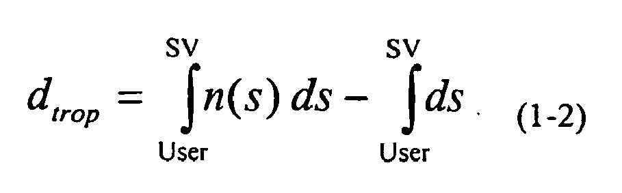
- s is the distance along the propagation path.
- The first integral is along the curved propagation path; the second integral is along a geometric straight path.
- The differential equation describing the curved ray path can be expressed, in cartesian coordinates, as:

- where r = r(s) is the vector describing the ray path,
- s is the length of the curved ray path up to r ,
- n is the refractive index scalar field,
- ∇n, a vector field, is the gradient of n.
- The differential equation can be expanded as

- A first order ordinary differential equation (ODE) with known initial values can be solved using numerical methods: for example Runge-Kutta or Adams-Moulton methods. Higher order differential equations can be solved numerically by rewriting them as an equivalent system of first order equations. Using the substitution r 1 = r and r 2 = r' (the first derivative), the ray path differential equation (1-4) can be expressed as an equivalent system of two first order differential equations 1-5 and 1-6:


- The determination of the ray path therefore amounts to the solution of a system of two ODEs with initial values. Standard numerical methods can be used to solve the problem: for example, a Runge-Kutta method with adaptive step control consistent with user defined tolerances.
- With the ray path solved, the tropospheric delay can be computed as:

Figure 3(a) . Point b corresponds to the point at which ray curvature and refractivity can be assumed to be negligible, in this specification above an altitude of 70km. - The ray-tracing process to determine the path from user to satellite (a to b in
Fig. 3(a) ) starts at point a and assumes a starting elevation angle of αApparent. Although the precise satellite position and therefore αTrue is known, αApparent (such that the ray path intersects point c) can initially only be estimated. Because ray tracing starts off at an angle that is at best a guess, the resultant ray path will in general not intersect point c. By deriving at least two ray traces and using interpolation or iterative methods it is possible to establish an angle of suitable accuracy from which tropospheric delay is derived. The present invention is predicated upon deriving for use a more accurate value for each tropospheric delay. - At least part of tropospheric delay determination is based upon Numerical Weather Prediction (NWP) modelling which forecasts the evolution of atmospheric physical processes by applying governing equations, including the conservation of mass, momentum and energy. Three-dimensional fields of continuous variables including humidity, pressure, temperature and velocity are numerically processed and meteorological features, including weather fronts, are secondary derived properties. A variety of measurements can be input into the numerical model including surface, radiosonde and satellite observations. The water cycle is modelled including the effects of terrain moisture, sea surface temperature, cloud formation and precipitation.
- Numerical models can be global or of limited area. Limited area high-resolution models are often termed mesoscale models as they reflect mesoscale meteorological features,weather patterns of less than 100km in size.
- The UK Meteorological Office has and makes available so-called Unified Models of mesoscale and global data. The NWP model maps each define a grid over the map's coverage region and the models provide tropospheric delays at corresponding points. For example, the UKMO has two NWP models, the so-called global model and the mesoscale model. The former has a horizontal resolution of 0.8333 degrees (5/6 degrees) in longitude and 0.5555 degrees (5/9 degrees) in latitude giving a grid of 432 x 325 points defining the earths surface, each point associated with a cell of about 60km at mid latitudes and about 90km in the tropics. This global map may be used inter alia to provide boundary points for a mesoscale model which is a regional model centred on the British Isles and has a resolution of 0.11 degrees in longitude and latitude (the grid being rotated with a shiftied pole to maintain uniform horizontal resolution) and has 146 x 182 grid points which correspond to an array of cells of approximately 12km x 12km. Both models have 38 vertical levels and extend to about 40km.
- At any grid point of the relevant map The atmospheric refractive index (and therefore the gradient of the refractive index) can be derived from numerical weather prediction model pressure, water vapour partial pressure and temperature fields. Atmospheric refractivity can be divided into dry (hydrostatic) and wet components. A simple two-term expression having a refractivity accuracy of 0.5% is:


- N is the refractivity.
- n is the refractive index
- P is atmospheric pressure (millibar)
- e is the water vapour pressure (millibar)
- T is temperature (Kelvin)
- The numerical weather prediction fields to be used are expressed in a spherical coordinate frame, it is computationally convenient, therefore, to generate the refractivity gradient in spherical coordinates (r,θ,α), which can be converted into local curveilinear coordinates (u,v,w) using the following transformation.

- A further rotational transformation is then applied to the local curveiliner coordinate frame to give the gradient in a fixed cartesian frame (x,y,z in
Fig. 3(b) ) suitable for numerically solving equations 1-5 and 1-6. - NWP field values between grid-points can be linearly and log-linearly interpolated. Linear and log-linear extrapolation techniques can be used to extend the NWP fields beyond the highest grid-point and below the NWP terrain. For an accurate construction of the refractive index field, account must be taken of the variation of gravitational acceleration with height and latitude. Hydrostatic equilibrium can be assumed. With the three-dimensional refractive index field (n) defined, the ray path equations can be solved and the tropospheric delay computed using Equation 1-2.
- The atmospheric refractive index can be divided into dry (hydrostatic) and wet components. The wet component possesses the larger spatial and temporal variability. It is often convenient to divide total zenith delays into wet and dry zenith delays. The hydrostatic zenith delay can be accurately modelled given a surface pressure measurement, however the wet zenith delay can not be accurately determined from surface humidity measurements, as they are not representative of the above atmosphere.
- In order to aid understanding reference is made briefly to discussing the presentation of tropospheric delays as so-called "wet" and "dry" components and elevation mapping as applied thereto.
- In modelling tropospheric delay, it is convenient in accordance with the first model, to relate the tropospheric delay at a given elevation angle, ε, to the zenith delay


- The hydrostatic zenith delay can be accurately modelled given a surface pressure measurement but the wet zenith delay can not be accurately determined from surface humidity measurements, as they are not representative of the above atmosphere. The expression for the tropospheric delay at a given elevation angle can be defined as:

- It is noted that care must taken when applying the simplification of the superposition of hydrostatic and wet atmospheric delays: the propagation path is dependent upon both hydrostatic and wet components.
- Hydrostatic and wet mapping functions according to the Niell methodology possess a high degree of accuracy without the need for prior meteorological information, and the variation of tropospheric delay with elevation angle can be efficiently modelled by a continued fraction expansion.
- Meteorological features that possess a large spatial and/or temporal variation in tropospheric delay will impact the accuracy of NWP-derived tropospheric corrections and the bandwidth required for dissemination on a regional or global basis. The temporal and spatial variation in hydrostatic refractivity is generally small, whereas meteorological features associated with rapid changes in atmospheric moisture significantly impact the accuracy/bandwidth relationship.
- Meteorological features smaller than the resolution of the numerical prediction model will not be accurately reflected in the NWP-derived tropospheric correction.
- A weather front marks the interface between air masses: defined as a large body of air whose physical properties are largely uniform horizontally for hundreds of kilometres. The front can mark the occurrence of abrupt changes in atmospheric moisture, temperature and therefore refractivity. Fronts can be divided into three classifications: warm, cold and occluded.
- The most rapid change in tropospheric delay is likely to occur when satellite elevation and front inclination are equal. Generally, in the UK, frontal systems move at 30 to 50 kilometres per hour and can result in zenith delay variations of 3 cm/hour. Tropospheric delays vary in accordance with inclination to earth insofar as they are ray-tracing is taking place through meteorological features that vary differently with both altitude and position.
- The
server 200 thus takes as input regional or global numerical weather prediction model information including pressure, temperature and humidity data and computes the three-dimensional refractive index field from the meteorological data. Wet and dry tropospheric delays are derived for a gridded area, corresponding to the NWP coverage, at heights corresponding to a terrain database (that may be the NWP terrain). These are transformed to, or initially computed as zenith delays For the same grid locations including height, wet and dry zenith delays are computed from the first model 210. - The server, in computing the the difference between first model and meteorological model, and thus the modifications required to the first model zenith delays to makethewm accurate, derives these diferences each as a fractional change from the first model value, as a percentage.
- There are two benfits to this. Firstly it is found that notwithstanding the actual values of the delays and the differences, the differences lie in a small range (approximately ± 10%) from the corresponding first model values; this permits developing a smaller range of correction values to transmit than if actial value differences were used. Secondly, it provides for better correction of first model zenith delay values by interpolation.
- A correction, BC %, defined as a percentage correction to the first model that includes the variation of zenith delay with height is transmitted. The corrections are in the form of a gridded data set. The user can linearly interpolate their tropospheric correction from the adjacent set points.

-

-

- h 0 is the height above mean sea level at which the broadcast correction percentage is computed,
- φ is the latitude at which the broadcast correction percentage is computed,
- λ is the longitude at which the broadcast correction percentage is computed.
- The user can compute the zenith delay as:

- BCint% is the interpolated correction percentage,
- h 1 is the user height.
- It should be noted that this technique avoids requiring the user receiver to store the NWP terrain data set, which, as the NWP model evolves, is likely to change. If the user is located at one of the grid-points corresponding to the broadcast corrections and at h 1=h 0 , the user applied tropospheric correction is equal to

- It will be appreciated that particularly for communicating by satellite and more particularly by GNSS satellites there is a limit on transmission bandwidth. Although improvements may in the future ease this restriction, for the present it is necessary to plan to transmit data at less than 500 bit/s and typically 200 to 250 bits/s. This is exacerbated by the satellites not being available to transmit at all times, but only within certain transmission windows. To this end, it is appropriate that the correction data derived from the models is suitable for data reduction.
- The NWP model maps each define a grid over the map's coverage region and the models provide zenith delays at corresponding points, and thus a set of differences (modifications or corrections) is defined corresponding to said geographical points. Thus for a particular set of meteorological information at a particular time, the server can compile a matrix array of such zenith delay modifications for the various locations of the organisation's map coverage.
- For example, as mentioned above, the UKMO has two NWP models, the so-called global model and the mesoscale model. The former has a resolution giving a grid of 432 x 325 points defining the earths surface, and the mesoscale model which is a regional model centred on the British Isles has 146 x 182 grid points.
- Thus there exists a two-dimensional matrix array of point correction sets each represented by a multi-bit word. In particular this can as in this embodiment be represented by an 8-bit word.
- Thus there exists in the base station, and based upon the particular UM of interest a geographical distribution of corrections, essentially an 8-bit greyscale map image of the corrections. To the extent that it helps understanding, such a map is capable of being represented visually and
Figure 4 comprises such a representation of a global correction map. - Whereas the visual display representation is actually / according to the information and its dissemination, it will be appreciated that the format of the information lends itself to data compression techniques employed with such two-dimensional images in order to reduce the size of the data file or information for dissemination.
- A lossless or lossy compression map be employed, but in this embodiments the server effects a lossy image compression ; the preferred compression is in accordance with the JPEG2000 standard (wavelet-based) although other standards, such as JPEG (cosine based) or other techniques such as simple sub-sampling may be used, to reduce the file size of the information.
- At this point it is appropriate to refer again to the user receiver. Insofar as the correction data signal is received from the GNSS (or the) satellite with the usual signals, no special receiving circuitry is needed. The correction (image) data set is passed to processor zenith delay computation which decodes the image for use of the individual pixel values as corrections as described above. Such decoding may be accomplished by a hardware feature built into the receiver or such decoding may be achieved by software loaded into the central processor of receiver; software for JPEG image file decompression is well known
- For example, if the file size of the uncompressed image is about 141 kb a compression factor of 35 (reducing files size to 4kb) indicates little compression noise, but in a greater compression of 140 (to 1kb) compression noise is evident. This is also shown graphically in
Figure 5 . - It will be appreciated that the conditions for wet delay functions are far more complex and produce greater file sizes than dry delay functions. Thus separating wet and dry delay functions which can reasonably expect compressed file sizes of the
order 9 kb and 1 kb respectively, there is need to disseminate about 88,000 bits. - This data set may be transmitted as a single image to all satellites of a constellation group. In this embodiment, the ability to effect data transmission at such a low rate is achieved by effecting the transmission to the GNSS satellites, with the full images at high transmission rate / long duration or only part of the image associated with the map region associated with a particular satellite or split amongst the satellites for each too receive only the part related to it, permitting a further factor of three reduction in required reception time; that is, transmission and reception would take about 2 minutes at a data rate of 250 bits/sec.
- Thus each of the GNSS satellites is able to broadcast, with the normal signals, correction signals that each user receiver can employ with the zenith tropospheric delay modelling to effect a correction to values employed with the model in accordance with substantially current meteorological conditions pertaining to its location.
- It will be appreciated that the rate of data dissemination is of both technical and economic importance. Firstly, the data transmission capacity available for slotting in the additional information is limited, at least in current implementations of GNSS.
- Whereas for other types of data the solution may be to prolong the duration of the transmission event, in the case of updating weather dependent data this is not a suitable option. Insofar as weather changes and weather features move over the earth's surface and thus the grids employed in the meteorological model, there is a currency element, that is, a time interval and/or distance for which a desired tropospheric delay value is valid. It is believed that such currency time is of the order of one hour and/or grid size of 50 to 90 km. Thus, is a user is to rely upon meteorogically generally tropospheric delay values (by way of a correction) it should be within such validity time or position for which generated. Thus, in terms of transmission o a user, transmission must be at such a rate that the user can receive and process the information while it is still valid. Satellite transmission rates are both slow in bit rate and intermittent in availability for downloading such correction information. Thus, there is an imperative to effect a data reduction to accommodate transfer of a correction data (image) set whilst the data retains viability.
- Furthermore, the time taken to download the correction data (image) set should not be unduly long as to cause the user to decline to wait for the time it takes to effect the download, decompress the image data file and compute position.
- Thus, it is important to effect the degree of data reduction/image compression that achieves these various objectives.
- Having regard to the above discussion of viability of delay values (and derived corrections) it should be noted that employing data based on NWP model approach it is in practice possible to predict the weather conditions and derive tropospheric delays for any given point in advance, up to several hours, notwithstanding that the viability of predicted tropospheric delay is relatively small (as described above) once current for the predicted time.
- Therefore, it is possible to develop not only a set of tropospheric delays (as Zenith tropospheric delays) associated with a regions grid points but also to develop corresponding sets predicted for times in the future. That is, the server can derive a prediction set of correction sets.
- This may be useful if the server can only devote itself periodically to developing delay corrections, as the prediction set can be stored and its members, correction sets for a particular time, be retrieved when that time is current and the set valid.
- Alternatively, such a prediction set could be transmitted and stored within the satellite for retrieval and re-transmission of correction sets at times for which the validity is current, or analogously stored in the receiver for retrieval.
- Notwithstanding the ability to both produce and upload prediction sets of data, in practice, at the moment, the data transmission bottle neck is downloading from the satellite (particularly a GNSS satellite) to the user.
- In order to reduce the size of the correction data set filed to be transmitted by a satellite to a user, it may be arranged to transmit only delay corrections applicable to users within range, that is, within sight of the satellite, whilst ignoring data for users at other points of the globe. This may be achieved by the server determining which part of the correction data set to upload to any particular satellite, having regard to users who can access it, or the server may upload global data set but the satellite determine which part of the set to re-transmit.
- The above description has concentrated on describing the derivation, communication and usage of corrections to Zenith tropospheric delays which represent major sources of positioning errors not correctable by the user receiver first model.
- As mentioned above, the first model also employs a mapping function that employs parameters that also depend upon the atmosphere and are accommodated by elements used in the climate model, that is, a function of time of year (a) latitude (b) and altitude (c). These may also be corrected by correction sets derived in the server. This mapping function may be expressed as:

- This may be further expressed as:

- By a fitting process operated such that sum of the squares of the residuals between the equation (2-2) and the ray traced (truth) is minimised. Thus a set of correction values may be derived composed of Δa, Δb and Δc as a similar data image file or superimposed upon the Zenith correction data image file by increasing the word length thereof to include word elements comprising these corrections.
- Transmission and reception anti-coding is as before except that the receiver now has correction values to employ with the parameters of the mapping function whereby both the Zenith delay and its mat values are more accurately represented.
- It will be appreciated that it is possible to include in elevation mapping functions the parameters of longitude and time of day, and the above approach to deriving a numerical solution therefor may be extended thereto.
- Although it is convenient and in many ways advantageous to employ NWP, other meteorological sources may be used on combination therewith to augment the data available. Any other meteorological model that takes a three dimensional view of the atmosphere may be employed instead of the NWP. As will be appreciated, the NWP derives tropospheric delays are defined for a grid having a cell size limited by the NWP model in use. Many weather features that have a high moisture content and can effect tropospheric delay, such a thunder storms, may be below the resolution threshold of the NWP model. However, there exists a number of sources of data such as satellite images of an essentially dimensional nature that can identify with high resolution the existence of such features and the information contained therein can be employed to vary the NWP values for a particular cell of the grid to take such features into account across the NWP grid.
- The above described embodiment is intended to enable a user receiver having a built in first, non-meteorological model to determine its position more accurately than is possible by use of the model alone. It will be appreciated that part of the computation solution is to derive a time values to the accuracy permitted by the model's interpretation of tropospheric delay. For some users, it is the time function that is of importance and such user may know the precise location of a fixed receiver.
- The above disclosure may be summarised as follows:
- The tropospheric correction server takes as input regional or global numerical weather prediction model information including pressure, temperature and humidity data. Additional meteorological data, for example high-resolution water vapour estimates from infrared satellite observations, could be used to augment NWP data and aid in the correction of very small meteorological features (for example local convective storms).
- The tropospheric correction server computes the three-dimensional refractive index field from the meteorological data. Wet and dry zenith delays are computed for a gridded area, corresponding to the NWP coverage, at heights corresponding to a terrain database (that may be the NWP terrain). In the case of the
server 200, for the same grid locations including height, wet and dry zenith delays are computed from a prior model. The server then computes the difference between prior and meteorological observation based zenith delays as a percentage. The gridded data set of wet and dry percentage corrections are then quantised and compressed using a lossy image compression technique. The compressed image, including data required for image decoding, is then disseminated to the satellite uplink station (part of the satellite navigation system ground infrastructure). The image data relates to the current atmospheric state and may also include several hours of predicted images. The uploading of data can be from one or more uplink stations and can be uplinked to one or more satellites. The data can be global or regional in nature. The data sent to each satellite can be area-limited such that the satellite constellation provides global coverage although each satellite's data. - The batch-uploading to satellites of several hours of predicted images may be used to reduce the burden on the satellite navigation system ground infrastructure. Each satellite broadcasts the most applicable, most current, tropospheric image as part of the satellite navigation system's navigation data.
- The user's satellite navigation signal tracking system receives the tropospheric images, the standard navigation data including satellite orbit determination parameters and makes pseudorange and accumulated carrier observations. The wet and dry compressed tropospheric correction images are decompressed. The prior wet and dry zenith delays are computed. The prior wet and dry zenith delay model is the same as that used in the tropospheric correction server. The user wet and dry zenith delays, corresponding to the user location, is then computed using interpolation between adjacent gridded data points.
- Wet and dry zenith propagation delays are then converted into satellite specific pseudorange corrections using satellite elevation mapping functions. Finally the standard navigation solution is computed, but with the addition of meteorological observation-based tropospheric delay corrections.
- A more comprehensive discussion on the factors that affect the implementation of a positioning system, numerical weather prediction techniques and deriving corrected tropospheric delay information from meteorological measurements, and based may be found in the paper " Tropospheric Delay Modelling and Correction Dissemination using Numerical Weather Prediction Fields " by M Powe, J Butcher and J Owen given in the Proceedings of GNSS 2003.
Claims (34)
- A method of obtaining tropospheric delay data for use in increasing the accuracy with which the location of a user receiver (220) in a global navigation satellite system (GNSS) (100) can be determined, the method comprising the steps of
generating a first set of approximate tropospheric delay values applicable to various user receiver geographical locations from a first model (230), which is known per se, at a location (200) remote from said user receiver;
generating a second set of tropospheric delay values that are accurate and applicable to said various user receiver geographical locations from a second model, which is a meteorological model at a location remote from said user receiver;
developing a set of tropospheric delay value modifications (260) applicable to said first model so that together, said first model and said tropospheric delay value modifications can provide a set of tropospheric delay values substantially in agreement with said second set of tropospheric delay values, and
communicating said set of tropospheric delay value modifications to said user receiver for modifying approximate tropospheric delay values of said user receiver. - A method according to claim 1 wherein the first model is based on non-meteorological parameters.
- A method according to claim 2 wherein said non-meteorological parameters comprise at least one of time of year, latitude and altitude.
- A method according to claim 3 wherein said non-meteorological parameters comprise at least one of longitude and time of day.
- A method according to any one of claims 1 to 4 wherein said sets of tropospheric delay values comprises zenith tropospheric delay values.
- A method according to claim 5 wherein the first modes contains a mapping function relating tropospheric delay values at a given elevation angle to the zenith tropospheric delay values.
- A method according to claim 6 wherein said set of tropospheric delay value modifications comprise a set of modifications for use with the mapping function of the first model.
- A method according to any one of claims 1 to 7 wherein the delay value modifications are the differences between corresponding values of- the first set of approximate tropospheric delay values attributable to the first model and- the second set of accurate tropospheric delay values attributable to the second model, which is a meteorological model.
- A method according to claim 8 in which the delay value modifications are expressed as a fractional change from the values of the first set of tropospheric delay values.
- A method according to any one of claims 1 to 9 wherein the set of delay value modifications is expressed as a data array, each modification having a value which is determined for an individual grid point on at least a part of the earth's surface.
- A method according to claim 10 wherein said set of modifications is expressed as a digital data file.
- A method according to claim 11 wherein said digital data file is a greyscale image of multi-bit words, each word representing a location of the region.
- A method according to claim 12 comprising the further steps of applying data reduction (270) to the set of tropospheric delay value modifications to derive a reduced set of tropospheric delay value modifications for communication to a user.
- A method according to claim 13 wherein the data reduction is an image compression process.
- A method according to claim 13 or claim 14 comprising reducing the data size by lossy data reduction.
- A method according to claim 15 comprising effecting data reduction by reducing the correction set data file according to a JPEG 2000 or JPEG 90 standard.
- A method according to any preceding claim wherein said accurate tropospheric delay values are derived by a ray tracing technique.
- A method according to claim 17 wherein said accurate tropospheric delay values are derived by three-dimensional refractive index field generation.
- A method according to any preceding claim wherein said meteorological model is based on numerical weather prediction (NWP) data for a region of the earth.
- A method according to any one of claims 17 to 19 therein said meteorological model or each said tropospheric delay value modification is augmented by directly observed meteorological data.
- A method according to claim 20 wherein said directly observed data has a resolution smaller than the NWP data.
- A method according to claim 20 or claim 21 wherein said directly observed meteorological data is derived as a data set relating to a region of the earth's surface corresponding to at least part of the NWP data.
- A method as claimed in any one of claims 19 to 22 wherein said region is substantially global.
- A method as claimed in any one of claims 17 to 23 comprising predicting accurate tropospheric delay values for in the future from said meteorological information and developing a prediction set of delay value modifications for said geographic region of the earth's surface, whereby each member of said prediction set describes a delay value modification that becomes current as a function of time from development.
- A method according to any one of the preceding claims whereby the set of tropospheric delay value modifications is communicated to said receiver on a communication channel or data link.
- A method as claimed in claim 25 when dependant claim 24 comprising communicating said prediction set of delay value modifications as a batch and using members of the set as the time for which each was predicted becomes current in respect of the forecast.
- A method according to any preceding claim comprising communicating at least part of the set of delay value modifications to at least one orbiting satellite (1101, 1102 ...) and re-transmitting at least part of said set to said receiver from a said orbiting satellite.
- A method according to any preceding claim wherein only that part of the set of delay value modifications that can be of use to a receiver in a region within range of a satellite (1101, 1102...) is communicated to said satellite.
- A method according to claim 13 and any claim dependent thereon comprising applying data reduction sufficient to permit transmission of all or part of said set of delay value modifications useable by said receiver within a time dictated by transmission availability and transmission rate of the satellite, said time being substantially lower than the validity time of the meteorological information used by the meteorological model.
- A method according to claim 29 wherein the data reduction is arranged to permit delay value modification data transmission to a receiver at a data rate in the range 25 to 500 bits/s.
- A method according to claim 30 wherein the data reduction is arranged to permit delay value modification data transmission in the range 200 to 250 bits/s.
- Apparatus comprising means adapted to carry out the methods of any of claims 1-31.
- A global navigation satellite system (GNSS) receiver (220) which can compute, with greater accuracy, the location of said receiver, or the current time, said receiver comprising
means (130) operable to generated from an on-board model of non-meteorological data a first set of approximate tropospheric delay values applicable to signals received from a plurality of said satellites and compute an approximate position of the receiver relative to earth's surface or time,
characterized in that the receiver also comprises
means operable to receive a set of tropospheric delay value modifications previously derived from meteorological data,
means to correct the first set of approximate tropospheric delay values in accordance with the set of tropospheric delay value modifications,
and means to compute the location of the receiver or the time. - A receiver as claimed in claim 33 wherein said means to correct the first set of approximate tropospheric delay values is operable to effect one of interpolation and extrapolation of said modifications according to the computed position of the user relative to locations for which the modifications have been derived.
Applications Claiming Priority (3)
| Application Number | Priority Date | Filing Date | Title |
|---|---|---|---|
| GB0308894A GB0308894D0 (en) | 2003-04-17 | 2003-04-17 | Tropospheric delays in global positioning systems |
| GB0309142A GB0309142D0 (en) | 2003-04-23 | 2003-04-23 | Tropospheric delays in global positioning systems |
| PCT/GB2004/001676 WO2004095055A1 (en) | 2003-04-17 | 2004-04-19 | Correction of troposphere induced errors in global positioning systems |
Publications (2)
| Publication Number | Publication Date |
|---|---|
| EP1613978A1 EP1613978A1 (en) | 2006-01-11 |
| EP1613978B1 true EP1613978B1 (en) | 2010-12-29 |
Family
ID=33312362
Family Applications (1)
| Application Number | Title | Priority Date | Filing Date |
|---|---|---|---|
| EP04728200A Expired - Lifetime EP1613978B1 (en) | 2003-04-17 | 2004-04-19 | Correction of troposphere induced errors in global positioning systems |
Country Status (13)
| Country | Link |
|---|---|
| US (1) | US7877207B2 (en) |
| EP (1) | EP1613978B1 (en) |
| JP (1) | JP2006523836A (en) |
| KR (1) | KR101100531B1 (en) |
| CN (1) | CN1774645A (en) |
| AT (1) | ATE493676T1 (en) |
| AU (1) | AU2004232832B2 (en) |
| CA (1) | CA2519808C (en) |
| DE (1) | DE602004030777D1 (en) |
| ES (1) | ES2356821T3 (en) |
| NO (1) | NO20055398L (en) |
| RU (1) | RU2348052C2 (en) |
| WO (1) | WO2004095055A1 (en) |
Families Citing this family (67)
| Publication number | Priority date | Publication date | Assignee | Title |
|---|---|---|---|---|
| US7379707B2 (en) * | 2004-08-26 | 2008-05-27 | Raysat Antenna Systems, L.L.C. | System for concurrent mobile two-way data communications and TV reception |
| US20060176843A1 (en) * | 2005-02-07 | 2006-08-10 | Yoel Gat | Method and apparatus for providing low bit rate satellite television to moving vehicles |
| US7705793B2 (en) * | 2004-06-10 | 2010-04-27 | Raysat Antenna Systems | Applications for low profile two way satellite antenna system |
| US8761663B2 (en) * | 2004-01-07 | 2014-06-24 | Gilat Satellite Networks, Ltd | Antenna system |
| US7911400B2 (en) * | 2004-01-07 | 2011-03-22 | Raysat Antenna Systems, L.L.C. | Applications for low profile two-way satellite antenna system |
| US20110215985A1 (en) * | 2004-06-10 | 2011-09-08 | Raysat Antenna Systems, L.L.C. | Applications for Low Profile Two Way Satellite Antenna System |
| US7907087B2 (en) * | 2006-05-05 | 2011-03-15 | Nokia Corporation | Satellite based positioning of a wireless terminal |
| JP4901365B2 (en) * | 2006-08-23 | 2012-03-21 | 古野電気株式会社 | Positioning system, positioning method and positioning program |
| JP4910676B2 (en) * | 2006-12-15 | 2012-04-04 | セイコーエプソン株式会社 | Arithmetic circuit, positioning device, index calculation method and program |
| EP2003468B1 (en) * | 2007-06-13 | 2015-09-16 | Airbus DS GmbH | Dissemination of critical atmospheric conditions within global and regional navigation satellite systems |
| US7739048B2 (en) * | 2007-06-18 | 2010-06-15 | The Boeing Company | Method and system for determining water vapor profile using GPS signals |
| US8665146B2 (en) | 2007-07-10 | 2014-03-04 | Electronic Navigation Research Institute | Calculation method of the amount of zenith troposphere delay, and a correcting method of troposphere delay of satellite positioning signal |
| DE102007036497A1 (en) * | 2007-08-01 | 2009-02-19 | Astrium Gmbh | Positioning device and positioning method for a satellite navigation system |
| EP2040090A1 (en) * | 2007-09-18 | 2009-03-25 | Leica Geosystems AG | Method for accuracy estimation of network based corrections for a satellite-aided positioning system |
| US7869951B1 (en) * | 2008-07-11 | 2011-01-11 | Lockheed Martin Corporation | Method of determining local electromagnetic sensor refractivity |
| EP2944332B1 (en) | 2009-07-10 | 2016-08-17 | Boston Scientific Scimed, Inc. | Use of nanocrystals for a drug delivery balloon |
| AT508966A1 (en) * | 2009-10-30 | 2011-05-15 | Teleconsult Austria Gmbh | METHOD AND DEVICE FOR TRANSMITTING SATELLITE NAVIGATION DATA |
| CN101706571B (en) * | 2009-11-05 | 2012-08-29 | 宁波市气象服务中心 | Method for processing non-meteorological noise in radar echoes |
| CN102346252B (en) * | 2010-08-06 | 2013-06-05 | 清华大学 | Method and system for compensating atmospheric refraction in optical satellite remote sensing data geographic positioning |
| KR101183582B1 (en) * | 2010-09-29 | 2012-09-17 | 주식회사 에스원 | Differential GPS |
| JP5570649B2 (en) * | 2011-02-22 | 2014-08-13 | 三菱電機株式会社 | POSITIONING REINFORCEMENT INFORMATION GENERATION DEVICE AND POSITIONING REINFORCEMENT SYSTEM |
| US9972198B2 (en) * | 2011-03-22 | 2018-05-15 | Vaisala Oyj | Method for launching and a radiosonde |
| US8604966B1 (en) * | 2011-07-11 | 2013-12-10 | Lockheed Martin Corporation | Correction of radar beam refraction using electro-optical measurements |
| US8787944B2 (en) * | 2011-08-18 | 2014-07-22 | Rivada Research, Llc | Method and system for providing enhanced location based information for wireless handsets |
| FR2987899B1 (en) * | 2012-03-09 | 2014-05-02 | Thales Sa | ADAPTIVE METHOD FOR ESTIMATING THE ELECTRONIC CONTENT OF THE IONOSPHERE |
| US9322926B2 (en) * | 2012-03-30 | 2016-04-26 | Qualcomm Technologies International, Ltd. | Method and apparatus for synchronization and precise time computation for GNSS receivers |
| US20140091967A1 (en) * | 2012-09-28 | 2014-04-03 | Global Geophysical Services, Inc. | Seismic Data Acquisition Module with Broadband Antenna, and Corresponding Systems, Devices, Components and Methods |
| FR2998976B1 (en) * | 2012-11-30 | 2015-01-16 | Thales Sa | METHOD AND SYSTEM FOR DETERMINING AN ERROR FOR ESTIMATING THE TIME OF IONOSPHERE TRAVERSE |
| CN103033833B (en) * | 2012-12-13 | 2014-12-10 | 中国航天科工信息技术研究院 | Method of correcting troposphere delaying errors |
| CN103885046A (en) * | 2012-12-20 | 2014-06-25 | 河南省电力勘测设计院 | InSAR atmosphere delay correction method based on GPS |
| KR101448223B1 (en) * | 2013-03-20 | 2014-10-15 | 대한민국 | A System and method for flood detection using satellite observation, and Record media recorded program for realizing the same method |
| WO2014163069A1 (en) * | 2013-04-01 | 2014-10-09 | 株式会社次世代技術研究所 | Radar signal processing method and device |
| FR3025610B1 (en) * | 2014-09-05 | 2022-01-14 | Centre Nat Etd Spatiales | METHOD FOR COLLABORATIVE DETERMINATION OF POSITIONING ERRORS OF A SATELLITE NAVIGATION SYSTEM |
| CA2971273A1 (en) * | 2014-12-22 | 2016-06-30 | User-Centric Ip, L.P. | Mesoscale modeling |
| CN104656108B (en) * | 2015-02-12 | 2017-05-10 | 东南大学 | Sparse reference station network zenith troposphere delay modeling method considering elevation difference |
| GB2538101A (en) * | 2015-05-08 | 2016-11-09 | Esa | Interferometric radio occultation |
| RU2601387C1 (en) * | 2015-07-02 | 2016-11-10 | Александр Васильевич Тертышников | Method of determining auroral oval position and state of the earth's magnetic field |
| CN105137461A (en) * | 2015-09-01 | 2015-12-09 | 中国人民解放军63655部队 | Method for eliminating medium time delay of navigation positioning satellite system |
| US11047988B2 (en) | 2016-06-24 | 2021-06-29 | Rx Networks Inc. | Method and apparatus for reducing tropospheric effects in GNSS positioning |
| WO2018158125A1 (en) * | 2017-03-03 | 2018-09-07 | Deutsche Telekom Ag | Method, devices, system and computer program product for increasing the positioning accuracy of a mobile user equipment by using data of a global navigation satellite system |
| CN107991676B (en) * | 2017-12-01 | 2019-09-13 | 中国人民解放军国防科技大学 | Tropospheric Error Correction Method for Spaceborne Single Pass InSAR System |
| KR102522923B1 (en) * | 2018-12-24 | 2023-04-20 | 한국전자통신연구원 | Apparatus and method for estimating self-location of a vehicle |
| FR3092565B1 (en) * | 2019-02-08 | 2021-08-27 | Airbus Defence & Space Sas | Computer systems for the acquisition of satellite images taking into account meteorological uncertainty |
| CN109900973B (en) * | 2019-02-25 | 2021-06-01 | 西安电子科技大学 | Ray tracing method with light intensity attenuation based on regular rectangular refractive index unit |
| CN109900658B (en) * | 2019-03-06 | 2019-11-01 | 中国人民解放军国防科技大学 | Method for correcting atmospheric refraction of optical imaging satellite by using fixed star observation data |
| CN109901203B (en) * | 2019-03-27 | 2020-12-18 | 北京航空航天大学 | A ground-based augmentation system for high-precision prediction of tropospheric refractive index |
| KR102677918B1 (en) * | 2019-06-06 | 2024-06-25 | 스타 알리 인터내셔널 리미티드 | Single-epoch pseudo-range localization under variable ionospheric delay. |
| CN110673184A (en) * | 2019-09-05 | 2020-01-10 | 成都亿盟恒信科技有限公司 | High-precision positioning system and method based on vehicle |
| WO2021089541A1 (en) * | 2019-11-04 | 2021-05-14 | Moovement Holding B.V. | System and apparatus for the monitoring of livestock and the like |
| CN111753408B (en) * | 2020-06-09 | 2023-05-09 | 南京信息工程大学 | GNSS atmosphere weighted average temperature calculation method taking weather into consideration |
| KR102184290B1 (en) * | 2020-07-06 | 2020-11-30 | 아주대학교산학협력단 | Boresight Error Compensation Method in Satellite Antenna at Low Earth Orbit |
| WO2022015744A1 (en) * | 2020-07-13 | 2022-01-20 | Swift Navigation, Inc. | System and method for determining gnss positioning corrections |
| CN112034490B (en) * | 2020-10-10 | 2022-03-22 | 山东科技大学 | An improved method for NWP inversion of tropospheric delay |
| US12348910B2 (en) | 2020-12-23 | 2025-07-01 | Sony Group Corporation | Ground system and image processing method |
| KR20220108317A (en) * | 2021-01-27 | 2022-08-03 | 현대자동차주식회사 | Personal mobility, Server, and method controlling the server |
| CN113325448A (en) * | 2021-04-21 | 2021-08-31 | 中铁第一勘察设计院集团有限公司 | Large-altitude-difference CORS network resolving method considering troposphere delay reconstruction |
| CN114019584B (en) * | 2021-10-11 | 2024-06-14 | 武汉大学 | VRS (virtual reference Signal System) resolving method for high-precision CORS (continuous reference Signal System) network in large-height-difference region |
| CN114297939B (en) * | 2021-12-31 | 2022-09-16 | 山东大学 | Troposphere delay prediction method and system suitable for Antarctic region |
| CN116125495B (en) * | 2022-12-14 | 2024-04-16 | 北京六分科技有限公司 | Ionosphere correction determination method, ionosphere correction determination device, ionosphere correction determination storage medium, and ionosphere correction determination program product |
| CN116244265B (en) * | 2023-03-07 | 2023-08-18 | 国家海洋环境预报中心 | Processing method and device for marine weather numerical forecasting product and electronic equipment |
| CN116361714B (en) | 2023-06-01 | 2023-08-04 | 山东科技大学 | A Classification Method of Horizontal Tropospheric Delay Considering Non-isotropy |
| CN117629211B (en) * | 2023-11-14 | 2024-11-29 | 中国电子科技集团公司第七研究所 | A fast calculation method and system for refraction correction based on ray tracing |
| CN118311615B (en) * | 2024-03-29 | 2025-01-21 | 武汉大学 | A GNSS tropospheric and multipath joint modeling correction method and system |
| CN119165506B (en) * | 2024-11-15 | 2025-03-21 | 湖南大学 | A tropospheric error correction method, device, electronic device and storage medium |
| CN119254308B (en) * | 2024-12-04 | 2025-03-04 | 广州磐钴智能科技有限公司 | Method, device and storage medium for transmitting outdoor unattended equipment graph based on satellite |
| CN119902306B (en) * | 2025-03-31 | 2025-07-11 | 齐鲁工业大学(山东省科学院) | GNSS-based marine troposphere atmospheric parameter profile inversion method |
| CN120630257B (en) * | 2025-08-08 | 2025-11-21 | 中铁大桥局集团第二工程有限公司 | A BeiDou method for millimeter-level high-precision positioning over large sea areas |
Family Cites Families (7)
| Publication number | Priority date | Publication date | Assignee | Title |
|---|---|---|---|---|
| US5323322A (en) * | 1992-03-05 | 1994-06-21 | Trimble Navigation Limited | Networked differential GPS system |
| RU2092902C1 (en) * | 1993-12-27 | 1997-10-10 | Российский научно-исследовательский институт космического приборостроения | Method for detection of position of vehicle and device which implements said method |
| US5828336A (en) * | 1996-03-29 | 1998-10-27 | The United States Of America As Represented By The Administrator Of The National Aeronautics And Space Administration | Robust real-time wide-area differential GPS navigation |
| US6518921B1 (en) * | 1997-04-22 | 2003-02-11 | Ericsson Inc. | Cellular positioning system that compensates for received signal delays in positioning radio receivers |
| US6445340B2 (en) | 2000-01-26 | 2002-09-03 | Novatel, Inc. | Method and apparatus for generating a time signal |
| US7463195B2 (en) | 2001-06-21 | 2008-12-09 | Rosum Corporation | Position location using global positioning signals augmented by broadcast television signals |
| AUPR863401A0 (en) | 2001-11-02 | 2001-11-29 | Qx Corporation Pty Ltd | A method & device for precision time-lock |
-
2004
- 2004-04-19 US US10/553,682 patent/US7877207B2/en not_active Expired - Fee Related
- 2004-04-19 CA CA2519808A patent/CA2519808C/en not_active Expired - Fee Related
- 2004-04-19 ES ES04728200T patent/ES2356821T3/en not_active Expired - Lifetime
- 2004-04-19 JP JP2006506146A patent/JP2006523836A/en active Pending
- 2004-04-19 AU AU2004232832A patent/AU2004232832B2/en not_active Ceased
- 2004-04-19 AT AT04728200T patent/ATE493676T1/en not_active IP Right Cessation
- 2004-04-19 WO PCT/GB2004/001676 patent/WO2004095055A1/en not_active Ceased
- 2004-04-19 DE DE602004030777T patent/DE602004030777D1/en not_active Expired - Lifetime
- 2004-04-19 EP EP04728200A patent/EP1613978B1/en not_active Expired - Lifetime
- 2004-04-19 CN CNA2004800100625A patent/CN1774645A/en active Pending
- 2004-04-19 KR KR1020057019681A patent/KR101100531B1/en not_active Expired - Fee Related
- 2004-04-19 RU RU2005135641/09A patent/RU2348052C2/en not_active IP Right Cessation
-
2005
- 2005-11-15 NO NO20055398A patent/NO20055398L/en not_active Application Discontinuation
Also Published As
| Publication number | Publication date |
|---|---|
| JP2006523836A (en) | 2006-10-19 |
| WO2004095055A9 (en) | 2004-12-16 |
| ES2356821T3 (en) | 2011-04-13 |
| NO20055398D0 (en) | 2005-11-15 |
| US20070027624A1 (en) | 2007-02-01 |
| KR20060008899A (en) | 2006-01-27 |
| CA2519808A1 (en) | 2004-11-04 |
| CA2519808C (en) | 2012-06-12 |
| AU2004232832B2 (en) | 2009-03-05 |
| US7877207B2 (en) | 2011-01-25 |
| WO2004095055A1 (en) | 2004-11-04 |
| CN1774645A (en) | 2006-05-17 |
| DE602004030777D1 (en) | 2011-02-10 |
| NO20055398L (en) | 2006-01-04 |
| KR101100531B1 (en) | 2011-12-30 |
| WO2004095055A8 (en) | 2005-03-03 |
| AU2004232832A1 (en) | 2004-11-04 |
| RU2005135641A (en) | 2006-08-27 |
| EP1613978A1 (en) | 2006-01-11 |
| ATE493676T1 (en) | 2011-01-15 |
| RU2348052C2 (en) | 2009-02-27 |
Similar Documents
| Publication | Publication Date | Title |
|---|---|---|
| US7877207B2 (en) | Correction of troposphere induced errors in global positioning systems | |
| Hajj et al. | COSMIC GPS ionospheric sensing and space weather | |
| Zus et al. | The rapid and precise computation of GPS slant total delays and mapping factors utilizing a numerical weather model | |
| WO2019094255A1 (en) | Systems and methods for improved atmospheric monitoring and gps positioning utilizing gnss tomographic refractivity | |
| WO2022046317A2 (en) | System and method for providing gnss corrections | |
| US9625614B2 (en) | Systems and methods for atmospheric modeling based on GPS measurement | |
| Healy et al. | Assimilating GPS radio occultation measurements with two‐dimensional bending angle observation operators | |
| Jin et al. | Near real-time global ionospheric total electron content modeling and nowcasting based on GNSS observations: X. Jin, S. Song | |
| Kwon et al. | Implementation of a GPS-RO data processing system for the KIAPS-LETKF data assimilation system | |
| EP3475730B1 (en) | Method, apparatus and computer-readable medium for reducing tropospheric effects in gnss positioning | |
| García Fernández | Contributions to the 3D ionospheric sounding with GPS data | |
| Rózsa | Modelling tropospheric delays using the global surface meteorological parameter model GPT2 | |
| Guerova et al. | Global navigation satellite system monitoring of the atmosphere | |
| JP3611526B2 (en) | Satellite positioning system, its ground station and ground terminal | |
| Kutiev et al. | Real time 3-D electron density reconstruction over Europe by using TaD profiler | |
| Kumar et al. | Impact of single-point GPS integrated water vapor estimates on short-range WRF model forecasts over southern India | |
| Rocken et al. | Real-time ionospheric and atmospheric corrections for wide area single frequency carrier phase ambiguity resolution | |
| Cilliers et al. | The South African network of dual-frequency global positioning system satellite receiver base stations: a national asset with many applications and research opportunities: news & views | |
| Jupp et al. | Use of numerical weather prediction fields for the improvement of tropospheric corrections in global positioning applications | |
| Kačmařík et al. | New GNSS tomography of the atmosphere method–proposal and testing | |
| Skone et al. | Strategies for 4-D regional modeling of water vapour using GPS | |
| Wang et al. | Empirical Modeling of Tropospheric Delays and Uncertainty | |
| CN121741792A (en) | Global ionosphere modeling method and device based on Beidou single-frequency ionosphere weighted PPP | |
| Dodson et al. | Global positioning system as a passive integrated atmospheric water vapor sensing device | |
| DANLAMI | ASSESSMENT OF GNSS-BASED INTEGRATED WATER VAPOUR OVER NIGERIA CORS NETWORK |
Legal Events
| Date | Code | Title | Description |
|---|---|---|---|
| PUAI | Public reference made under article 153(3) epc to a published international application that has entered the european phase |
Free format text: ORIGINAL CODE: 0009012 |
|
| 17P | Request for examination filed |
Effective date: 20050930 |
|
| AK | Designated contracting states |
Kind code of ref document: A1 Designated state(s): AT BE BG CH CY CZ DE DK EE ES FI FR GB GR HU IE IT LI LU MC NL PL PT RO SE SI SK TR |
|
| AX | Request for extension of the european patent |
Extension state: AL HR LT LV MK |
|
| DAX | Request for extension of the european patent (deleted) | ||
| RIN1 | Information on inventor provided before grant (corrected) |
Inventor name: OWEN, JOHN, IFOR, REWBRIDGE Inventor name: POWE, MATTHEW, DUNCAN,NOTTINGHAM SCIENTIFIC LTD. Inventor name: BUTCHER, JAMES,D/IPR FORMALITIES SECTION |
|
| GRAP | Despatch of communication of intention to grant a patent |
Free format text: ORIGINAL CODE: EPIDOSNIGR1 |
|
| RIC1 | Information provided on ipc code assigned before grant |
Ipc: G01S 19/07 20100101AFI20100625BHEP |
|
| RIN1 | Information on inventor provided before grant (corrected) |
Inventor name: BUTCHER, JAMES,D/IPR FORMALITIES SECTION Inventor name: OWEN, JOHN, IFOR, REWBRIDGE Inventor name: POWE, MATTHEW, DUNCAN,NOTTINGHAM SCIENTIFIC LTD. |
|
| GRAS | Grant fee paid |
Free format text: ORIGINAL CODE: EPIDOSNIGR3 |
|
| GRAA | (expected) grant |
Free format text: ORIGINAL CODE: 0009210 |
|
| AK | Designated contracting states |
Kind code of ref document: B1 Designated state(s): AT BE BG CH CY CZ DE DK EE ES FI FR GB GR HU IE IT LI LU MC NL PL PT RO SE SI SK TR |
|
| REG | Reference to a national code |
Ref country code: GB Ref legal event code: FG4D |
|
| REG | Reference to a national code |
Ref country code: CH Ref legal event code: EP |
|
| REG | Reference to a national code |
Ref country code: IE Ref legal event code: FG4D |
|
| REF | Corresponds to: |
Ref document number: 602004030777 Country of ref document: DE Date of ref document: 20110210 Kind code of ref document: P |
|
| REG | Reference to a national code |
Ref country code: DE Ref legal event code: R096 Ref document number: 602004030777 Country of ref document: DE Effective date: 20110210 |
|
| REG | Reference to a national code |
Ref country code: CH Ref legal event code: NV Representative=s name: TROESCH SCHEIDEGGER WERNER AG |
|
| REG | Reference to a national code |
Ref country code: SE Ref legal event code: TRGR |
|
| REG | Reference to a national code |
Ref country code: NL Ref legal event code: T3 Ref country code: ES Ref legal event code: FG2A Ref document number: 2356821 Country of ref document: ES Kind code of ref document: T3 Effective date: 20110413 |
|
| PG25 | Lapsed in a contracting state [announced via postgrant information from national office to epo] |
Ref country code: BG Free format text: LAPSE BECAUSE OF FAILURE TO SUBMIT A TRANSLATION OF THE DESCRIPTION OR TO PAY THE FEE WITHIN THE PRESCRIBED TIME-LIMIT Effective date: 20110329 Ref country code: SI Free format text: LAPSE BECAUSE OF FAILURE TO SUBMIT A TRANSLATION OF THE DESCRIPTION OR TO PAY THE FEE WITHIN THE PRESCRIBED TIME-LIMIT Effective date: 20101229 Ref country code: AT Free format text: LAPSE BECAUSE OF FAILURE TO SUBMIT A TRANSLATION OF THE DESCRIPTION OR TO PAY THE FEE WITHIN THE PRESCRIBED TIME-LIMIT Effective date: 20101229 Ref country code: CY Free format text: LAPSE BECAUSE OF FAILURE TO SUBMIT A TRANSLATION OF THE DESCRIPTION OR TO PAY THE FEE WITHIN THE PRESCRIBED TIME-LIMIT Effective date: 20101229 |
|
| PG25 | Lapsed in a contracting state [announced via postgrant information from national office to epo] |
Ref country code: EE Free format text: LAPSE BECAUSE OF FAILURE TO SUBMIT A TRANSLATION OF THE DESCRIPTION OR TO PAY THE FEE WITHIN THE PRESCRIBED TIME-LIMIT Effective date: 20101229 Ref country code: PT Free format text: LAPSE BECAUSE OF FAILURE TO SUBMIT A TRANSLATION OF THE DESCRIPTION OR TO PAY THE FEE WITHIN THE PRESCRIBED TIME-LIMIT Effective date: 20110429 Ref country code: GR Free format text: LAPSE BECAUSE OF FAILURE TO SUBMIT A TRANSLATION OF THE DESCRIPTION OR TO PAY THE FEE WITHIN THE PRESCRIBED TIME-LIMIT Effective date: 20110330 Ref country code: CZ Free format text: LAPSE BECAUSE OF FAILURE TO SUBMIT A TRANSLATION OF THE DESCRIPTION OR TO PAY THE FEE WITHIN THE PRESCRIBED TIME-LIMIT Effective date: 20101229 |
|
| PG25 | Lapsed in a contracting state [announced via postgrant information from national office to epo] |
Ref country code: RO Free format text: LAPSE BECAUSE OF FAILURE TO SUBMIT A TRANSLATION OF THE DESCRIPTION OR TO PAY THE FEE WITHIN THE PRESCRIBED TIME-LIMIT Effective date: 20101229 Ref country code: SK Free format text: LAPSE BECAUSE OF FAILURE TO SUBMIT A TRANSLATION OF THE DESCRIPTION OR TO PAY THE FEE WITHIN THE PRESCRIBED TIME-LIMIT Effective date: 20101229 Ref country code: PL Free format text: LAPSE BECAUSE OF FAILURE TO SUBMIT A TRANSLATION OF THE DESCRIPTION OR TO PAY THE FEE WITHIN THE PRESCRIBED TIME-LIMIT Effective date: 20101229 |
|
| PG25 | Lapsed in a contracting state [announced via postgrant information from national office to epo] |
Ref country code: DK Free format text: LAPSE BECAUSE OF FAILURE TO SUBMIT A TRANSLATION OF THE DESCRIPTION OR TO PAY THE FEE WITHIN THE PRESCRIBED TIME-LIMIT Effective date: 20101229 |
|
| PLBE | No opposition filed within time limit |
Free format text: ORIGINAL CODE: 0009261 |
|
| STAA | Information on the status of an ep patent application or granted ep patent |
Free format text: STATUS: NO OPPOSITION FILED WITHIN TIME LIMIT |
|
| PG25 | Lapsed in a contracting state [announced via postgrant information from national office to epo] |
Ref country code: MC Free format text: LAPSE BECAUSE OF NON-PAYMENT OF DUE FEES Effective date: 20110430 |
|
| 26N | No opposition filed |
Effective date: 20110930 |
|
| REG | Reference to a national code |
Ref country code: DE Ref legal event code: R097 Ref document number: 602004030777 Country of ref document: DE Effective date: 20110930 |
|
| REG | Reference to a national code |
Ref country code: IE Ref legal event code: MM4A |
|
| PG25 | Lapsed in a contracting state [announced via postgrant information from national office to epo] |
Ref country code: IE Free format text: LAPSE BECAUSE OF NON-PAYMENT OF DUE FEES Effective date: 20110419 |
|
| PGFP | Annual fee paid to national office [announced via postgrant information from national office to epo] |
Ref country code: BE Payment date: 20120418 Year of fee payment: 9 Ref country code: DE Payment date: 20120420 Year of fee payment: 9 Ref country code: NL Payment date: 20120425 Year of fee payment: 9 Ref country code: CH Payment date: 20120420 Year of fee payment: 9 |
|
| PGFP | Annual fee paid to national office [announced via postgrant information from national office to epo] |
Ref country code: FR Payment date: 20120507 Year of fee payment: 9 Ref country code: SE Payment date: 20120418 Year of fee payment: 9 Ref country code: GB Payment date: 20120419 Year of fee payment: 9 |
|
| PGFP | Annual fee paid to national office [announced via postgrant information from national office to epo] |
Ref country code: IT Payment date: 20120426 Year of fee payment: 9 |
|
| PGFP | Annual fee paid to national office [announced via postgrant information from national office to epo] |
Ref country code: ES Payment date: 20120425 Year of fee payment: 9 |
|
| PG25 | Lapsed in a contracting state [announced via postgrant information from national office to epo] |
Ref country code: LU Free format text: LAPSE BECAUSE OF NON-PAYMENT OF DUE FEES Effective date: 20110419 |
|
| PGFP | Annual fee paid to national office [announced via postgrant information from national office to epo] |
Ref country code: FI Payment date: 20130411 Year of fee payment: 10 |
|
| PG25 | Lapsed in a contracting state [announced via postgrant information from national office to epo] |
Ref country code: TR Free format text: LAPSE BECAUSE OF FAILURE TO SUBMIT A TRANSLATION OF THE DESCRIPTION OR TO PAY THE FEE WITHIN THE PRESCRIBED TIME-LIMIT Effective date: 20101229 |
|
| BERE | Be: lapsed |
Owner name: THE SECRETARY OF STATE FOR DEFENCE Effective date: 20130430 |
|
| PG25 | Lapsed in a contracting state [announced via postgrant information from national office to epo] |
Ref country code: HU Free format text: LAPSE BECAUSE OF FAILURE TO SUBMIT A TRANSLATION OF THE DESCRIPTION OR TO PAY THE FEE WITHIN THE PRESCRIBED TIME-LIMIT Effective date: 20101229 |
|
| REG | Reference to a national code |
Ref country code: NL Ref legal event code: V1 Effective date: 20131101 |
|
| REG | Reference to a national code |
Ref country code: CH Ref legal event code: PL |
|
| REG | Reference to a national code |
Ref country code: SE Ref legal event code: EUG |
|
| GBPC | Gb: european patent ceased through non-payment of renewal fee |
Effective date: 20130419 |
|
| PG25 | Lapsed in a contracting state [announced via postgrant information from national office to epo] |
Ref country code: GB Free format text: LAPSE BECAUSE OF NON-PAYMENT OF DUE FEES Effective date: 20130419 Ref country code: DE Free format text: LAPSE BECAUSE OF NON-PAYMENT OF DUE FEES Effective date: 20131101 Ref country code: CH Free format text: LAPSE BECAUSE OF NON-PAYMENT OF DUE FEES Effective date: 20130430 Ref country code: BE Free format text: LAPSE BECAUSE OF NON-PAYMENT OF DUE FEES Effective date: 20130430 Ref country code: SE Free format text: LAPSE BECAUSE OF NON-PAYMENT OF DUE FEES Effective date: 20130420 Ref country code: LI Free format text: LAPSE BECAUSE OF NON-PAYMENT OF DUE FEES Effective date: 20130430 |
|
| REG | Reference to a national code |
Ref country code: FR Ref legal event code: ST Effective date: 20131231 |
|
| REG | Reference to a national code |
Ref country code: DE Ref legal event code: R119 Ref document number: 602004030777 Country of ref document: DE Effective date: 20131101 |
|
| PG25 | Lapsed in a contracting state [announced via postgrant information from national office to epo] |
Ref country code: FR Free format text: LAPSE BECAUSE OF NON-PAYMENT OF DUE FEES Effective date: 20130430 Ref country code: NL Free format text: LAPSE BECAUSE OF NON-PAYMENT OF DUE FEES Effective date: 20131101 Ref country code: IT Free format text: LAPSE BECAUSE OF NON-PAYMENT OF DUE FEES Effective date: 20130419 |
|
| PG25 | Lapsed in a contracting state [announced via postgrant information from national office to epo] |
Ref country code: FI Free format text: LAPSE BECAUSE OF NON-PAYMENT OF DUE FEES Effective date: 20140419 |
|
| REG | Reference to a national code |
Ref country code: ES Ref legal event code: FD2A Effective date: 20160105 |
|
| PG25 | Lapsed in a contracting state [announced via postgrant information from national office to epo] |
Ref country code: ES Free format text: LAPSE BECAUSE OF NON-PAYMENT OF DUE FEES Effective date: 20140420 |